JP2015125302A - Toner - Google Patents
Toner Download PDFInfo
- Publication number
- JP2015125302A JP2015125302A JP2013270112A JP2013270112A JP2015125302A JP 2015125302 A JP2015125302 A JP 2015125302A JP 2013270112 A JP2013270112 A JP 2013270112A JP 2013270112 A JP2013270112 A JP 2013270112A JP 2015125302 A JP2015125302 A JP 2015125302A
- Authority
- JP
- Japan
- Prior art keywords
- toner
- fine particles
- particles
- silica fine
- titanium oxide
- Prior art date
- Legal status (The legal status is an assumption and is not a legal conclusion. Google has not performed a legal analysis and makes no representation as to the accuracy of the status listed.)
- Granted
Links
- VYPSYNLAJGMNEJ-UHFFFAOYSA-N Silicium dioxide Chemical compound O=[Si]=O VYPSYNLAJGMNEJ-UHFFFAOYSA-N 0.000 claims abstract description 346
- 239000010419 fine particle Substances 0.000 claims abstract description 265
- 239000002245 particle Substances 0.000 claims abstract description 230
- 239000000377 silicon dioxide Substances 0.000 claims abstract description 170
- GWEVSGVZZGPLCZ-UHFFFAOYSA-N Titan oxide Chemical compound O=[Ti]=O GWEVSGVZZGPLCZ-UHFFFAOYSA-N 0.000 claims abstract description 107
- OGIDPMRJRNCKJF-UHFFFAOYSA-N titanium oxide Inorganic materials [Ti]=O OGIDPMRJRNCKJF-UHFFFAOYSA-N 0.000 claims abstract description 97
- 239000000654 additive Substances 0.000 claims abstract description 70
- 238000004833 X-ray photoelectron spectroscopy Methods 0.000 claims abstract description 7
- 238000009792 diffusion process Methods 0.000 claims description 61
- 230000000996 additive effect Effects 0.000 claims description 52
- 239000000178 monomer Substances 0.000 claims description 34
- 239000000203 mixture Substances 0.000 claims description 24
- 229920005989 resin Polymers 0.000 claims description 24
- 239000011347 resin Substances 0.000 claims description 24
- 239000003086 colorant Substances 0.000 claims description 17
- 239000011230 binding agent Substances 0.000 claims description 15
- 239000012736 aqueous medium Substances 0.000 claims description 13
- 230000000379 polymerizing effect Effects 0.000 claims description 2
- 238000012546 transfer Methods 0.000 abstract description 57
- 238000000034 method Methods 0.000 description 69
- 238000003756 stirring Methods 0.000 description 57
- 238000002156 mixing Methods 0.000 description 48
- -1 methyl hydrogen Chemical compound 0.000 description 45
- 238000005259 measurement Methods 0.000 description 38
- 239000000523 sample Substances 0.000 description 35
- XLYOFNOQVPJJNP-UHFFFAOYSA-N water Substances O XLYOFNOQVPJJNP-UHFFFAOYSA-N 0.000 description 34
- 238000004519 manufacturing process Methods 0.000 description 31
- 238000012545 processing Methods 0.000 description 27
- 239000007864 aqueous solution Substances 0.000 description 24
- 239000000696 magnetic material Substances 0.000 description 23
- 239000000463 material Substances 0.000 description 23
- 239000011164 primary particle Substances 0.000 description 23
- 230000000694 effects Effects 0.000 description 21
- 239000002253 acid Substances 0.000 description 20
- 230000008569 process Effects 0.000 description 20
- 239000002994 raw material Substances 0.000 description 20
- 239000007787 solid Substances 0.000 description 20
- 239000000047 product Substances 0.000 description 19
- 229920002545 silicone oil Polymers 0.000 description 19
- 238000012360 testing method Methods 0.000 description 19
- IJGRMHOSHXDMSA-UHFFFAOYSA-N Atomic nitrogen Chemical compound N#N IJGRMHOSHXDMSA-UHFFFAOYSA-N 0.000 description 18
- 239000006185 dispersion Substances 0.000 description 18
- 239000007788 liquid Substances 0.000 description 16
- 230000002093 peripheral effect Effects 0.000 description 16
- 230000000704 physical effect Effects 0.000 description 16
- 239000000126 substance Substances 0.000 description 16
- HEMHJVSKTPXQMS-UHFFFAOYSA-M Sodium hydroxide Chemical compound [OH-].[Na+] HEMHJVSKTPXQMS-UHFFFAOYSA-M 0.000 description 15
- PPBRXRYQALVLMV-UHFFFAOYSA-N Styrene Chemical compound C=CC1=CC=CC=C1 PPBRXRYQALVLMV-UHFFFAOYSA-N 0.000 description 15
- 239000001993 wax Substances 0.000 description 15
- 229910052751 metal Inorganic materials 0.000 description 14
- 239000002184 metal Substances 0.000 description 14
- 125000000391 vinyl group Chemical group [H]C([*])=C([H])[H] 0.000 description 14
- 239000006087 Silane Coupling Agent Substances 0.000 description 13
- 238000006243 chemical reaction Methods 0.000 description 13
- 239000003795 chemical substances by application Substances 0.000 description 13
- 230000006866 deterioration Effects 0.000 description 13
- UQSXHKLRYXJYBZ-UHFFFAOYSA-N iron oxide Inorganic materials [Fe]=O UQSXHKLRYXJYBZ-UHFFFAOYSA-N 0.000 description 13
- 238000004458 analytical method Methods 0.000 description 12
- 239000007822 coupling agent Substances 0.000 description 12
- 150000002148 esters Chemical class 0.000 description 12
- 238000007254 oxidation reaction Methods 0.000 description 12
- XEEYBQQBJWHFJM-UHFFFAOYSA-N Iron Chemical compound [Fe] XEEYBQQBJWHFJM-UHFFFAOYSA-N 0.000 description 11
- 150000001875 compounds Chemical class 0.000 description 11
- 230000007423 decrease Effects 0.000 description 11
- 239000002002 slurry Substances 0.000 description 11
- 238000004381 surface treatment Methods 0.000 description 11
- 229920002554 vinyl polymer Polymers 0.000 description 11
- 108091008695 photoreceptors Proteins 0.000 description 10
- 239000003505 polymerization initiator Substances 0.000 description 10
- 239000010936 titanium Substances 0.000 description 10
- OKKJLVBELUTLKV-UHFFFAOYSA-N Methanol Chemical compound OC OKKJLVBELUTLKV-UHFFFAOYSA-N 0.000 description 9
- 230000001276 controlling effect Effects 0.000 description 9
- 239000003431 cross linking reagent Substances 0.000 description 9
- 235000014113 dietary fatty acids Nutrition 0.000 description 9
- 239000000194 fatty acid Substances 0.000 description 9
- 229930195729 fatty acid Natural products 0.000 description 9
- 238000000691 measurement method Methods 0.000 description 9
- 229910052757 nitrogen Inorganic materials 0.000 description 9
- 230000000052 comparative effect Effects 0.000 description 8
- 238000011156 evaluation Methods 0.000 description 8
- 229920001225 polyester resin Polymers 0.000 description 8
- 239000004645 polyester resin Substances 0.000 description 8
- 238000006116 polymerization reaction Methods 0.000 description 8
- 229910052710 silicon Inorganic materials 0.000 description 8
- 239000000243 solution Substances 0.000 description 8
- 238000005406 washing Methods 0.000 description 8
- NIXOWILDQLNWCW-UHFFFAOYSA-M Acrylate Chemical compound [O-]C(=O)C=C NIXOWILDQLNWCW-UHFFFAOYSA-M 0.000 description 7
- LFQSCWFLJHTTHZ-UHFFFAOYSA-N Ethanol Chemical compound CCO LFQSCWFLJHTTHZ-UHFFFAOYSA-N 0.000 description 7
- 150000008064 anhydrides Chemical class 0.000 description 7
- 239000013078 crystal Substances 0.000 description 7
- 125000004386 diacrylate group Chemical group 0.000 description 7
- 239000002270 dispersing agent Substances 0.000 description 7
- 238000001035 drying Methods 0.000 description 7
- 150000004665 fatty acids Chemical class 0.000 description 7
- 238000001914 filtration Methods 0.000 description 7
- FFUAGWLWBBFQJT-UHFFFAOYSA-N hexamethyldisilazane Chemical compound C[Si](C)(C)N[Si](C)(C)C FFUAGWLWBBFQJT-UHFFFAOYSA-N 0.000 description 7
- 230000002209 hydrophobic effect Effects 0.000 description 7
- 235000013980 iron oxide Nutrition 0.000 description 7
- 238000002844 melting Methods 0.000 description 7
- 230000008018 melting Effects 0.000 description 7
- 239000000843 powder Substances 0.000 description 7
- 238000010298 pulverizing process Methods 0.000 description 7
- 150000003839 salts Chemical class 0.000 description 7
- 239000010703 silicon Substances 0.000 description 7
- 239000006228 supernatant Substances 0.000 description 7
- 238000010558 suspension polymerization method Methods 0.000 description 7
- VZCYOOQTPOCHFL-UHFFFAOYSA-N trans-butenedioic acid Natural products OC(=O)C=CC(O)=O VZCYOOQTPOCHFL-UHFFFAOYSA-N 0.000 description 7
- 125000005907 alkyl ester group Chemical group 0.000 description 6
- 238000004140 cleaning Methods 0.000 description 6
- 239000000975 dye Substances 0.000 description 6
- 230000007062 hydrolysis Effects 0.000 description 6
- 238000006460 hydrolysis reaction Methods 0.000 description 6
- 238000012986 modification Methods 0.000 description 6
- 230000004048 modification Effects 0.000 description 6
- 239000002736 nonionic surfactant Substances 0.000 description 6
- 238000001179 sorption measurement Methods 0.000 description 6
- MYRTYDVEIRVNKP-UHFFFAOYSA-N 1,2-Divinylbenzene Chemical compound C=CC1=CC=CC=C1C=C MYRTYDVEIRVNKP-UHFFFAOYSA-N 0.000 description 5
- NIXOWILDQLNWCW-UHFFFAOYSA-N Acrylic acid Chemical compound OC(=O)C=C NIXOWILDQLNWCW-UHFFFAOYSA-N 0.000 description 5
- 238000004438 BET method Methods 0.000 description 5
- LYCAIKOWRPUZTN-UHFFFAOYSA-N Ethylene glycol Chemical compound OCCO LYCAIKOWRPUZTN-UHFFFAOYSA-N 0.000 description 5
- VZCYOOQTPOCHFL-OWOJBTEDSA-N Fumaric acid Chemical compound OC(=O)\C=C\C(O)=O VZCYOOQTPOCHFL-OWOJBTEDSA-N 0.000 description 5
- CERQOIWHTDAKMF-UHFFFAOYSA-M Methacrylate Chemical compound CC(=C)C([O-])=O CERQOIWHTDAKMF-UHFFFAOYSA-M 0.000 description 5
- 230000001133 acceleration Effects 0.000 description 5
- 239000003945 anionic surfactant Substances 0.000 description 5
- 229940018557 citraconic acid Drugs 0.000 description 5
- 239000003599 detergent Substances 0.000 description 5
- 230000006870 function Effects 0.000 description 5
- 239000007789 gas Substances 0.000 description 5
- 239000011521 glass Substances 0.000 description 5
- 230000005484 gravity Effects 0.000 description 5
- 238000010438 heat treatment Methods 0.000 description 5
- 230000007774 longterm Effects 0.000 description 5
- 230000007935 neutral effect Effects 0.000 description 5
- 239000011163 secondary particle Substances 0.000 description 5
- 238000000926 separation method Methods 0.000 description 5
- 235000011121 sodium hydroxide Nutrition 0.000 description 5
- 239000004094 surface-active agent Substances 0.000 description 5
- ARCGXLSVLAOJQL-UHFFFAOYSA-N trimellitic acid Chemical compound OC(=O)C1=CC=C(C(O)=O)C(C(O)=O)=C1 ARCGXLSVLAOJQL-UHFFFAOYSA-N 0.000 description 5
- SMZOUWXMTYCWNB-UHFFFAOYSA-N 2-(2-methoxy-5-methylphenyl)ethanamine Chemical compound COC1=CC=C(C)C=C1CCN SMZOUWXMTYCWNB-UHFFFAOYSA-N 0.000 description 4
- KAKZBPTYRLMSJV-UHFFFAOYSA-N Butadiene Chemical compound C=CC=C KAKZBPTYRLMSJV-UHFFFAOYSA-N 0.000 description 4
- VEXZGXHMUGYJMC-UHFFFAOYSA-N Hydrochloric acid Chemical compound Cl VEXZGXHMUGYJMC-UHFFFAOYSA-N 0.000 description 4
- OFOBLEOULBTSOW-UHFFFAOYSA-N Propanedioic acid Natural products OC(=O)CC(O)=O OFOBLEOULBTSOW-UHFFFAOYSA-N 0.000 description 4
- XUIMIQQOPSSXEZ-UHFFFAOYSA-N Silicon Chemical group [Si] XUIMIQQOPSSXEZ-UHFFFAOYSA-N 0.000 description 4
- KDYFGRWQOYBRFD-UHFFFAOYSA-N Succinic acid Natural products OC(=O)CCC(O)=O KDYFGRWQOYBRFD-UHFFFAOYSA-N 0.000 description 4
- CZMRCDWAGMRECN-UGDNZRGBSA-N Sucrose Chemical compound O[C@H]1[C@H](O)[C@@H](CO)O[C@@]1(CO)O[C@@H]1[C@H](O)[C@@H](O)[C@H](O)[C@@H](CO)O1 CZMRCDWAGMRECN-UGDNZRGBSA-N 0.000 description 4
- 229930006000 Sucrose Natural products 0.000 description 4
- QAOWNCQODCNURD-UHFFFAOYSA-N Sulfuric acid Chemical compound OS(O)(=O)=O QAOWNCQODCNURD-UHFFFAOYSA-N 0.000 description 4
- KKEYFWRCBNTPAC-UHFFFAOYSA-N Terephthalic acid Chemical compound OC(=O)C1=CC=C(C(O)=O)C=C1 KKEYFWRCBNTPAC-UHFFFAOYSA-N 0.000 description 4
- WYURNTSHIVDZCO-UHFFFAOYSA-N Tetrahydrofuran Chemical compound C1CCOC1 WYURNTSHIVDZCO-UHFFFAOYSA-N 0.000 description 4
- RTAQQCXQSZGOHL-UHFFFAOYSA-N Titanium Chemical compound [Ti] RTAQQCXQSZGOHL-UHFFFAOYSA-N 0.000 description 4
- 239000003513 alkali Substances 0.000 description 4
- 125000000217 alkyl group Chemical group 0.000 description 4
- 229910052782 aluminium Inorganic materials 0.000 description 4
- XAGFODPZIPBFFR-UHFFFAOYSA-N aluminium Chemical compound [Al] XAGFODPZIPBFFR-UHFFFAOYSA-N 0.000 description 4
- 125000000751 azo group Chemical group [*]N=N[*] 0.000 description 4
- 230000007547 defect Effects 0.000 description 4
- 238000010586 diagram Methods 0.000 description 4
- 239000008151 electrolyte solution Substances 0.000 description 4
- 238000011010 flushing procedure Methods 0.000 description 4
- 229910052742 iron Inorganic materials 0.000 description 4
- BAUYGSIQEAFULO-UHFFFAOYSA-L iron(2+) sulfate (anhydrous) Chemical compound [Fe+2].[O-]S([O-])(=O)=O BAUYGSIQEAFULO-UHFFFAOYSA-L 0.000 description 4
- 229910021506 iron(II) hydroxide Inorganic materials 0.000 description 4
- NCNCGGDMXMBVIA-UHFFFAOYSA-L iron(ii) hydroxide Chemical compound [OH-].[OH-].[Fe+2] NCNCGGDMXMBVIA-UHFFFAOYSA-L 0.000 description 4
- 239000011976 maleic acid Substances 0.000 description 4
- 150000002739 metals Chemical class 0.000 description 4
- 230000003647 oxidation Effects 0.000 description 4
- 239000002904 solvent Substances 0.000 description 4
- 239000003381 stabilizer Substances 0.000 description 4
- 239000005720 sucrose Substances 0.000 description 4
- 229910052719 titanium Inorganic materials 0.000 description 4
- 238000001132 ultrasonic dispersion Methods 0.000 description 4
- 238000004876 x-ray fluorescence Methods 0.000 description 4
- PUPZLCDOIYMWBV-UHFFFAOYSA-N (+/-)-1,3-Butanediol Chemical compound CC(O)CCO PUPZLCDOIYMWBV-UHFFFAOYSA-N 0.000 description 3
- PEDCQBHIVMGVHV-UHFFFAOYSA-N Glycerine Chemical compound OCC(O)CO PEDCQBHIVMGVHV-UHFFFAOYSA-N 0.000 description 3
- DNIAPMSPPWPWGF-UHFFFAOYSA-N Propylene glycol Chemical compound CC(O)CO DNIAPMSPPWPWGF-UHFFFAOYSA-N 0.000 description 3
- 229910004298 SiO 2 Inorganic materials 0.000 description 3
- 239000002250 absorbent Substances 0.000 description 3
- 230000002745 absorbent Effects 0.000 description 3
- YRKCREAYFQTBPV-UHFFFAOYSA-N acetylacetone Natural products CC(=O)CC(C)=O YRKCREAYFQTBPV-UHFFFAOYSA-N 0.000 description 3
- 150000008065 acid anhydrides Chemical class 0.000 description 3
- 150000007513 acids Chemical class 0.000 description 3
- 125000003118 aryl group Chemical group 0.000 description 3
- 230000015572 biosynthetic process Effects 0.000 description 3
- IISBACLAFKSPIT-UHFFFAOYSA-N bisphenol A Chemical class C=1C=C(O)C=CC=1C(C)(C)C1=CC=C(O)C=C1 IISBACLAFKSPIT-UHFFFAOYSA-N 0.000 description 3
- 238000007664 blowing Methods 0.000 description 3
- 238000004364 calculation method Methods 0.000 description 3
- 238000011109 contamination Methods 0.000 description 3
- 238000001816 cooling Methods 0.000 description 3
- 230000008878 coupling Effects 0.000 description 3
- 238000010168 coupling process Methods 0.000 description 3
- 238000005859 coupling reaction Methods 0.000 description 3
- 238000011161 development Methods 0.000 description 3
- MTHSVFCYNBDYFN-UHFFFAOYSA-N diethylene glycol Chemical compound OCCOCCO MTHSVFCYNBDYFN-UHFFFAOYSA-N 0.000 description 3
- JJQZDUKDJDQPMQ-UHFFFAOYSA-N dimethoxy(dimethyl)silane Chemical compound CO[Si](C)(C)OC JJQZDUKDJDQPMQ-UHFFFAOYSA-N 0.000 description 3
- 238000009826 distribution Methods 0.000 description 3
- 238000000921 elemental analysis Methods 0.000 description 3
- RTZKZFJDLAIYFH-UHFFFAOYSA-N ether Substances CCOCC RTZKZFJDLAIYFH-UHFFFAOYSA-N 0.000 description 3
- 239000011790 ferrous sulphate Substances 0.000 description 3
- 235000003891 ferrous sulphate Nutrition 0.000 description 3
- 239000001530 fumaric acid Substances 0.000 description 3
- 125000002887 hydroxy group Chemical group [H]O* 0.000 description 3
- 229910000359 iron(II) sulfate Inorganic materials 0.000 description 3
- 239000002609 medium Substances 0.000 description 3
- NYGZLYXAPMMJTE-UHFFFAOYSA-M metanil yellow Chemical group [Na+].[O-]S(=O)(=O)C1=CC=CC(N=NC=2C=CC(NC=3C=CC=CC=3)=CC=2)=C1 NYGZLYXAPMMJTE-UHFFFAOYSA-M 0.000 description 3
- LVHBHZANLOWSRM-UHFFFAOYSA-N methylenebutanedioic acid Natural products OC(=O)CC(=C)C(O)=O LVHBHZANLOWSRM-UHFFFAOYSA-N 0.000 description 3
- 229910001172 neodymium magnet Inorganic materials 0.000 description 3
- 239000012860 organic pigment Substances 0.000 description 3
- 150000003961 organosilicon compounds Chemical class 0.000 description 3
- 150000002978 peroxides Chemical class 0.000 description 3
- XNGIFLGASWRNHJ-UHFFFAOYSA-N phthalic acid Chemical class OC(=O)C1=CC=CC=C1C(O)=O XNGIFLGASWRNHJ-UHFFFAOYSA-N 0.000 description 3
- 238000002360 preparation method Methods 0.000 description 3
- 238000003825 pressing Methods 0.000 description 3
- 238000007639 printing Methods 0.000 description 3
- 230000001105 regulatory effect Effects 0.000 description 3
- 230000000630 rising effect Effects 0.000 description 3
- 229910000077 silane Inorganic materials 0.000 description 3
- 238000005563 spheronization Methods 0.000 description 3
- 239000007858 starting material Substances 0.000 description 3
- 235000011044 succinic acid Nutrition 0.000 description 3
- 150000005846 sugar alcohols Polymers 0.000 description 3
- 239000000725 suspension Substances 0.000 description 3
- 239000012808 vapor phase Substances 0.000 description 3
- 239000002699 waste material Substances 0.000 description 3
- WYTZZXDRDKSJID-UHFFFAOYSA-N (3-aminopropyl)triethoxysilane Chemical compound CCO[Si](OCC)(OCC)CCCN WYTZZXDRDKSJID-UHFFFAOYSA-N 0.000 description 2
- UAJRSHJHFRVGMG-UHFFFAOYSA-N 1-ethenyl-4-methoxybenzene Chemical compound COC1=CC=C(C=C)C=C1 UAJRSHJHFRVGMG-UHFFFAOYSA-N 0.000 description 2
- OZAIFHULBGXAKX-UHFFFAOYSA-N 2-(2-cyanopropan-2-yldiazenyl)-2-methylpropanenitrile Chemical compound N#CC(C)(C)N=NC(C)(C)C#N OZAIFHULBGXAKX-UHFFFAOYSA-N 0.000 description 2
- LEJBBGNFPAFPKQ-UHFFFAOYSA-N 2-(2-prop-2-enoyloxyethoxy)ethyl prop-2-enoate Chemical compound C=CC(=O)OCCOCCOC(=O)C=C LEJBBGNFPAFPKQ-UHFFFAOYSA-N 0.000 description 2
- INQDDHNZXOAFFD-UHFFFAOYSA-N 2-[2-(2-prop-2-enoyloxyethoxy)ethoxy]ethyl prop-2-enoate Chemical compound C=CC(=O)OCCOCCOCCOC(=O)C=C INQDDHNZXOAFFD-UHFFFAOYSA-N 0.000 description 2
- HCLJOFJIQIJXHS-UHFFFAOYSA-N 2-[2-[2-(2-prop-2-enoyloxyethoxy)ethoxy]ethoxy]ethyl prop-2-enoate Chemical compound C=CC(=O)OCCOCCOCCOCCOC(=O)C=C HCLJOFJIQIJXHS-UHFFFAOYSA-N 0.000 description 2
- KUDUQBURMYMBIJ-UHFFFAOYSA-N 2-prop-2-enoyloxyethyl prop-2-enoate Chemical compound C=CC(=O)OCCOC(=O)C=C KUDUQBURMYMBIJ-UHFFFAOYSA-N 0.000 description 2
- ZGHFDIIVVIFNPS-UHFFFAOYSA-N 3-Methyl-3-buten-2-one Chemical compound CC(=C)C(C)=O ZGHFDIIVVIFNPS-UHFFFAOYSA-N 0.000 description 2
- XDLMVUHYZWKMMD-UHFFFAOYSA-N 3-trimethoxysilylpropyl 2-methylprop-2-enoate Chemical compound CO[Si](OC)(OC)CCCOC(=O)C(C)=C XDLMVUHYZWKMMD-UHFFFAOYSA-N 0.000 description 2
- VNGLVZLEUDIDQH-UHFFFAOYSA-N 4-[2-(4-hydroxyphenyl)propan-2-yl]phenol;2-methyloxirane Chemical compound CC1CO1.C=1C=C(O)C=CC=1C(C)(C)C1=CC=C(O)C=C1 VNGLVZLEUDIDQH-UHFFFAOYSA-N 0.000 description 2
- XKRFYHLGVUSROY-UHFFFAOYSA-N Argon Chemical compound [Ar] XKRFYHLGVUSROY-UHFFFAOYSA-N 0.000 description 2
- 229930185605 Bisphenol Natural products 0.000 description 2
- VTYYLEPIZMXCLO-UHFFFAOYSA-L Calcium carbonate Chemical compound [Ca+2].[O-]C([O-])=O VTYYLEPIZMXCLO-UHFFFAOYSA-L 0.000 description 2
- FBPFZTCFMRRESA-FSIIMWSLSA-N D-Glucitol Natural products OC[C@H](O)[C@H](O)[C@@H](O)[C@H](O)CO FBPFZTCFMRRESA-FSIIMWSLSA-N 0.000 description 2
- FBPFZTCFMRRESA-JGWLITMVSA-N D-glucitol Chemical compound OC[C@H](O)[C@@H](O)[C@H](O)[C@H](O)CO FBPFZTCFMRRESA-JGWLITMVSA-N 0.000 description 2
- RRHGJUQNOFWUDK-UHFFFAOYSA-N Isoprene Chemical compound CC(=C)C=C RRHGJUQNOFWUDK-UHFFFAOYSA-N 0.000 description 2
- KFZMGEQAYNKOFK-UHFFFAOYSA-N Isopropanol Chemical compound CC(C)O KFZMGEQAYNKOFK-UHFFFAOYSA-N 0.000 description 2
- YIVJZNGAASQVEM-UHFFFAOYSA-N Lauroyl peroxide Chemical compound CCCCCCCCCCCC(=O)OOC(=O)CCCCCCCCCCC YIVJZNGAASQVEM-UHFFFAOYSA-N 0.000 description 2
- BAPJBEWLBFYGME-UHFFFAOYSA-N Methyl acrylate Chemical compound COC(=O)C=C BAPJBEWLBFYGME-UHFFFAOYSA-N 0.000 description 2
- PXHVJJICTQNCMI-UHFFFAOYSA-N Nickel Chemical compound [Ni] PXHVJJICTQNCMI-UHFFFAOYSA-N 0.000 description 2
- OAICVXFJPJFONN-UHFFFAOYSA-N Phosphorus Chemical compound [P] OAICVXFJPJFONN-UHFFFAOYSA-N 0.000 description 2
- 229920003171 Poly (ethylene oxide) Polymers 0.000 description 2
- BLRPTPMANUNPDV-UHFFFAOYSA-N Silane Chemical compound [SiH4] BLRPTPMANUNPDV-UHFFFAOYSA-N 0.000 description 2
- CDBYLPFSWZWCQE-UHFFFAOYSA-L Sodium Carbonate Chemical compound [Na+].[Na+].[O-]C([O-])=O CDBYLPFSWZWCQE-UHFFFAOYSA-L 0.000 description 2
- FAPWRFPIFSIZLT-UHFFFAOYSA-M Sodium chloride Chemical compound [Na+].[Cl-] FAPWRFPIFSIZLT-UHFFFAOYSA-M 0.000 description 2
- 238000002441 X-ray diffraction Methods 0.000 description 2
- NOZAQBYNLKNDRT-UHFFFAOYSA-N [diacetyloxy(ethenyl)silyl] acetate Chemical compound CC(=O)O[Si](OC(C)=O)(OC(C)=O)C=C NOZAQBYNLKNDRT-UHFFFAOYSA-N 0.000 description 2
- WNLRTRBMVRJNCN-UHFFFAOYSA-N adipic acid Chemical compound OC(=O)CCCCC(O)=O WNLRTRBMVRJNCN-UHFFFAOYSA-N 0.000 description 2
- 230000002411 adverse Effects 0.000 description 2
- 150000001298 alcohols Chemical class 0.000 description 2
- 150000001338 aliphatic hydrocarbons Chemical class 0.000 description 2
- 125000003545 alkoxy group Chemical group 0.000 description 2
- AZDRQVAHHNSJOQ-UHFFFAOYSA-N alumane Chemical group [AlH3] AZDRQVAHHNSJOQ-UHFFFAOYSA-N 0.000 description 2
- VSCWAEJMTAWNJL-UHFFFAOYSA-K aluminium trichloride Chemical compound Cl[Al](Cl)Cl VSCWAEJMTAWNJL-UHFFFAOYSA-K 0.000 description 2
- 150000001408 amides Chemical class 0.000 description 2
- PYKYMHQGRFAEBM-UHFFFAOYSA-N anthraquinone Natural products CCC(=O)c1c(O)c2C(=O)C3C(C=CC=C3O)C(=O)c2cc1CC(=O)OC PYKYMHQGRFAEBM-UHFFFAOYSA-N 0.000 description 2
- TZCXTZWJZNENPQ-UHFFFAOYSA-L barium sulfate Chemical compound [Ba+2].[O-]S([O-])(=O)=O TZCXTZWJZNENPQ-UHFFFAOYSA-L 0.000 description 2
- 239000002585 base Substances 0.000 description 2
- 239000000981 basic dye Substances 0.000 description 2
- 235000019437 butane-1,3-diol Nutrition 0.000 description 2
- WERYXYBDKMZEQL-UHFFFAOYSA-N butane-1,4-diol Chemical compound OCCCCO WERYXYBDKMZEQL-UHFFFAOYSA-N 0.000 description 2
- KDYFGRWQOYBRFD-NUQCWPJISA-N butanedioic acid Chemical compound O[14C](=O)CC[14C](O)=O KDYFGRWQOYBRFD-NUQCWPJISA-N 0.000 description 2
- CQEYYJKEWSMYFG-UHFFFAOYSA-N butyl acrylate Chemical compound CCCCOC(=O)C=C CQEYYJKEWSMYFG-UHFFFAOYSA-N 0.000 description 2
- 239000001506 calcium phosphate Substances 0.000 description 2
- OSGAYBCDTDRGGQ-UHFFFAOYSA-L calcium sulfate Chemical compound [Ca+2].[O-]S([O-])(=O)=O OSGAYBCDTDRGGQ-UHFFFAOYSA-L 0.000 description 2
- 125000004432 carbon atom Chemical group C* 0.000 description 2
- 239000004203 carnauba wax Substances 0.000 description 2
- 235000013869 carnauba wax Nutrition 0.000 description 2
- 238000005119 centrifugation Methods 0.000 description 2
- 230000008859 change Effects 0.000 description 2
- IJOOHPMOJXWVHK-UHFFFAOYSA-N chlorotrimethylsilane Chemical compound C[Si](C)(C)Cl IJOOHPMOJXWVHK-UHFFFAOYSA-N 0.000 description 2
- HNEGQIOMVPPMNR-IHWYPQMZSA-N citraconic acid Chemical compound OC(=O)C(/C)=C\C(O)=O HNEGQIOMVPPMNR-IHWYPQMZSA-N 0.000 description 2
- 239000011362 coarse particle Substances 0.000 description 2
- 229910017052 cobalt Inorganic materials 0.000 description 2
- 239000010941 cobalt Substances 0.000 description 2
- GUTLYIVDDKVIGB-UHFFFAOYSA-N cobalt atom Chemical compound [Co] GUTLYIVDDKVIGB-UHFFFAOYSA-N 0.000 description 2
- 239000002131 composite material Substances 0.000 description 2
- 239000012141 concentrate Substances 0.000 description 2
- 238000007796 conventional method Methods 0.000 description 2
- 238000001514 detection method Methods 0.000 description 2
- ZZNQQQWFKKTOSD-UHFFFAOYSA-N diethoxy(diphenyl)silane Chemical compound C=1C=CC=CC=1[Si](OCC)(OCC)C1=CC=CC=C1 ZZNQQQWFKKTOSD-UHFFFAOYSA-N 0.000 description 2
- 238000007865 diluting Methods 0.000 description 2
- 125000000118 dimethyl group Chemical group [H]C([H])([H])* 0.000 description 2
- YYLGKUPAFFKGRQ-UHFFFAOYSA-N dimethyldiethoxysilane Chemical compound CCO[Si](C)(C)OCC YYLGKUPAFFKGRQ-UHFFFAOYSA-N 0.000 description 2
- 229910001873 dinitrogen Inorganic materials 0.000 description 2
- 239000002612 dispersion medium Substances 0.000 description 2
- 238000004090 dissolution Methods 0.000 description 2
- NOPFSRXAKWQILS-UHFFFAOYSA-N docosan-1-ol Chemical compound CCCCCCCCCCCCCCCCCCCCCCO NOPFSRXAKWQILS-UHFFFAOYSA-N 0.000 description 2
- POULHZVOKOAJMA-UHFFFAOYSA-N dodecanoic acid Chemical compound CCCCCCCCCCCC(O)=O POULHZVOKOAJMA-UHFFFAOYSA-N 0.000 description 2
- 238000005516 engineering process Methods 0.000 description 2
- FJKIXWOMBXYWOQ-UHFFFAOYSA-N ethenoxyethane Chemical compound CCOC=C FJKIXWOMBXYWOQ-UHFFFAOYSA-N 0.000 description 2
- FWDBOZPQNFPOLF-UHFFFAOYSA-N ethenyl(triethoxy)silane Chemical compound CCO[Si](OCC)(OCC)C=C FWDBOZPQNFPOLF-UHFFFAOYSA-N 0.000 description 2
- NKSJNEHGWDZZQF-UHFFFAOYSA-N ethenyl(trimethoxy)silane Chemical compound CO[Si](OC)(OC)C=C NKSJNEHGWDZZQF-UHFFFAOYSA-N 0.000 description 2
- 238000011049 filling Methods 0.000 description 2
- LNTHITQWFMADLM-UHFFFAOYSA-N gallic acid Chemical compound OC(=O)C1=CC(O)=C(O)C(O)=C1 LNTHITQWFMADLM-UHFFFAOYSA-N 0.000 description 2
- 238000005227 gel permeation chromatography Methods 0.000 description 2
- 238000005469 granulation Methods 0.000 description 2
- 230000003179 granulation Effects 0.000 description 2
- IPCSVZSSVZVIGE-UHFFFAOYSA-N hexadecanoic acid Chemical compound CCCCCCCCCCCCCCCC(O)=O IPCSVZSSVZVIGE-UHFFFAOYSA-N 0.000 description 2
- RSKGMYDENCAJEN-UHFFFAOYSA-N hexadecyl(trimethoxy)silane Chemical compound CCCCCCCCCCCCCCCC[Si](OC)(OC)OC RSKGMYDENCAJEN-UHFFFAOYSA-N 0.000 description 2
- CZWLNMOIEMTDJY-UHFFFAOYSA-N hexyl(trimethoxy)silane Chemical compound CCCCCC[Si](OC)(OC)OC CZWLNMOIEMTDJY-UHFFFAOYSA-N 0.000 description 2
- 150000002430 hydrocarbons Chemical group 0.000 description 2
- 239000001257 hydrogen Substances 0.000 description 2
- 229910052739 hydrogen Inorganic materials 0.000 description 2
- 230000003301 hydrolyzing effect Effects 0.000 description 2
- 230000006872 improvement Effects 0.000 description 2
- YDZQQRWRVYGNER-UHFFFAOYSA-N iron;titanium;trihydrate Chemical compound O.O.O.[Ti].[Fe] YDZQQRWRVYGNER-UHFFFAOYSA-N 0.000 description 2
- NNPPMTNAJDCUHE-UHFFFAOYSA-N isobutane Chemical compound CC(C)C NNPPMTNAJDCUHE-UHFFFAOYSA-N 0.000 description 2
- QQVIHTHCMHWDBS-UHFFFAOYSA-N isophthalic acid Chemical compound OC(=O)C1=CC=CC(C(O)=O)=C1 QQVIHTHCMHWDBS-UHFFFAOYSA-N 0.000 description 2
- 239000004816 latex Substances 0.000 description 2
- 229920000126 latex Polymers 0.000 description 2
- HQKMJHAJHXVSDF-UHFFFAOYSA-L magnesium stearate Chemical compound [Mg+2].CCCCCCCCCCCCCCCCCC([O-])=O.CCCCCCCCCCCCCCCCCC([O-])=O HQKMJHAJHXVSDF-UHFFFAOYSA-L 0.000 description 2
- 230000005415 magnetization Effects 0.000 description 2
- VZCYOOQTPOCHFL-UPHRSURJSA-N maleic acid Chemical compound OC(=O)\C=C/C(O)=O VZCYOOQTPOCHFL-UPHRSURJSA-N 0.000 description 2
- 239000011572 manganese Substances 0.000 description 2
- POPACFLNWGUDSR-UHFFFAOYSA-N methoxy(trimethyl)silane Chemical compound CO[Si](C)(C)C POPACFLNWGUDSR-UHFFFAOYSA-N 0.000 description 2
- HNEGQIOMVPPMNR-UHFFFAOYSA-N methylfumaric acid Natural products OC(=O)C(C)=CC(O)=O HNEGQIOMVPPMNR-UHFFFAOYSA-N 0.000 description 2
- BFXIKLCIZHOAAZ-UHFFFAOYSA-N methyltrimethoxysilane Chemical compound CO[Si](C)(OC)OC BFXIKLCIZHOAAZ-UHFFFAOYSA-N 0.000 description 2
- 238000006386 neutralization reaction Methods 0.000 description 2
- 239000012299 nitrogen atmosphere Substances 0.000 description 2
- BDJRBEYXGGNYIS-UHFFFAOYSA-N nonanedioic acid Chemical compound OC(=O)CCCCCCCC(O)=O BDJRBEYXGGNYIS-UHFFFAOYSA-N 0.000 description 2
- UTOPWMOLSKOLTQ-UHFFFAOYSA-N octacosanoic acid Chemical compound CCCCCCCCCCCCCCCCCCCCCCCCCCCC(O)=O UTOPWMOLSKOLTQ-UHFFFAOYSA-N 0.000 description 2
- GLDOVTGHNKAZLK-UHFFFAOYSA-N octadecan-1-ol Chemical compound CCCCCCCCCCCCCCCCCCO GLDOVTGHNKAZLK-UHFFFAOYSA-N 0.000 description 2
- SLYCYWCVSGPDFR-UHFFFAOYSA-N octadecyltrimethoxysilane Chemical compound CCCCCCCCCCCCCCCCCC[Si](OC)(OC)OC SLYCYWCVSGPDFR-UHFFFAOYSA-N 0.000 description 2
- MSRJTTSHWYDFIU-UHFFFAOYSA-N octyltriethoxysilane Chemical compound CCCCCCCC[Si](OCC)(OCC)OCC MSRJTTSHWYDFIU-UHFFFAOYSA-N 0.000 description 2
- 239000003960 organic solvent Substances 0.000 description 2
- 230000010355 oscillation Effects 0.000 description 2
- 239000003002 pH adjusting agent Substances 0.000 description 2
- 239000008188 pellet Substances 0.000 description 2
- 239000012071 phase Substances 0.000 description 2
- 229910052698 phosphorus Inorganic materials 0.000 description 2
- 239000011574 phosphorus Substances 0.000 description 2
- 239000000049 pigment Substances 0.000 description 2
- 238000007747 plating Methods 0.000 description 2
- 239000011148 porous material Substances 0.000 description 2
- 239000002244 precipitate Substances 0.000 description 2
- CYIDZMCFTVVTJO-UHFFFAOYSA-N pyromellitic acid Chemical compound OC(=O)C1=CC(C(O)=O)=C(C(O)=O)C=C1C(O)=O CYIDZMCFTVVTJO-UHFFFAOYSA-N 0.000 description 2
- 238000011002 quantification Methods 0.000 description 2
- 230000009257 reactivity Effects 0.000 description 2
- 229920006395 saturated elastomer Polymers 0.000 description 2
- CXMXRPHRNRROMY-UHFFFAOYSA-N sebacic acid Chemical compound OC(=O)CCCCCCCCC(O)=O CXMXRPHRNRROMY-UHFFFAOYSA-N 0.000 description 2
- 239000011734 sodium Substances 0.000 description 2
- 239000000600 sorbitol Substances 0.000 description 2
- 125000006850 spacer group Chemical group 0.000 description 2
- 230000000087 stabilizing effect Effects 0.000 description 2
- 238000003860 storage Methods 0.000 description 2
- YLQBMQCUIZJEEH-UHFFFAOYSA-N tetrahydrofuran Natural products C=1C=COC=1 YLQBMQCUIZJEEH-UHFFFAOYSA-N 0.000 description 2
- QORWJWZARLRLPR-UHFFFAOYSA-H tricalcium bis(phosphate) Chemical compound [Ca+2].[Ca+2].[Ca+2].[O-]P([O-])([O-])=O.[O-]P([O-])([O-])=O QORWJWZARLRLPR-UHFFFAOYSA-H 0.000 description 2
- CPUDPFPXCZDNGI-UHFFFAOYSA-N triethoxy(methyl)silane Chemical compound CCO[Si](C)(OCC)OCC CPUDPFPXCZDNGI-UHFFFAOYSA-N 0.000 description 2
- XYJRNCYWTVGEEG-UHFFFAOYSA-N trimethoxy(2-methylpropyl)silane Chemical compound CO[Si](OC)(OC)CC(C)C XYJRNCYWTVGEEG-UHFFFAOYSA-N 0.000 description 2
- NMEPHPOFYLLFTK-UHFFFAOYSA-N trimethoxy(octyl)silane Chemical compound CCCCCCCC[Si](OC)(OC)OC NMEPHPOFYLLFTK-UHFFFAOYSA-N 0.000 description 2
- ZNOCGWVLWPVKAO-UHFFFAOYSA-N trimethoxy(phenyl)silane Chemical compound CO[Si](OC)(OC)C1=CC=CC=C1 ZNOCGWVLWPVKAO-UHFFFAOYSA-N 0.000 description 2
- 150000004670 unsaturated fatty acids Chemical class 0.000 description 2
- 235000021122 unsaturated fatty acids Nutrition 0.000 description 2
- 239000001060 yellow colorant Substances 0.000 description 2
- 229910052727 yttrium Inorganic materials 0.000 description 2
- FVQMJJQUGGVLEP-UHFFFAOYSA-N (2-methylpropan-2-yl)oxy 2-ethylhexaneperoxoate Chemical compound CCCCC(CC)C(=O)OOOC(C)(C)C FVQMJJQUGGVLEP-UHFFFAOYSA-N 0.000 description 1
- QEQBMZQFDDDTPN-UHFFFAOYSA-N (2-methylpropan-2-yl)oxy benzenecarboperoxoate Chemical compound CC(C)(C)OOOC(=O)C1=CC=CC=C1 QEQBMZQFDDDTPN-UHFFFAOYSA-N 0.000 description 1
- KDGNCLDCOVTOCS-UHFFFAOYSA-N (2-methylpropan-2-yl)oxy propan-2-yl carbonate Chemical compound CC(C)OC(=O)OOC(C)(C)C KDGNCLDCOVTOCS-UHFFFAOYSA-N 0.000 description 1
- JNYAEWCLZODPBN-JGWLITMVSA-N (2r,3r,4s)-2-[(1r)-1,2-dihydroxyethyl]oxolane-3,4-diol Chemical compound OC[C@@H](O)[C@H]1OC[C@H](O)[C@H]1O JNYAEWCLZODPBN-JGWLITMVSA-N 0.000 description 1
- DJVAVGIEGHKEQE-UHFFFAOYSA-N (3-methoxy-3-methylbutoxy) (3-methoxy-3-methylbutyl) carbonate Chemical compound COC(C)(C)CCOOC(=O)OCCC(C)(C)OC DJVAVGIEGHKEQE-UHFFFAOYSA-N 0.000 description 1
- CFQZKFWQLAHGSL-FNTYJUCDSA-N (3e,5e,7e,9e,11e,13e,15e,17e)-18-[(3e,5e,7e,9e,11e,13e,15e,17e)-18-[(3e,5e,7e,9e,11e,13e,15e)-octadeca-3,5,7,9,11,13,15,17-octaenoyl]oxyoctadeca-3,5,7,9,11,13,15,17-octaenoyl]oxyoctadeca-3,5,7,9,11,13,15,17-octaenoic acid Chemical compound OC(=O)C\C=C\C=C\C=C\C=C\C=C\C=C\C=C\C=C\OC(=O)C\C=C\C=C\C=C\C=C\C=C\C=C\C=C\C=C\OC(=O)C\C=C\C=C\C=C\C=C\C=C\C=C\C=C\C=C CFQZKFWQLAHGSL-FNTYJUCDSA-N 0.000 description 1
- CUXYLFPMQMFGPL-UHFFFAOYSA-N (9Z,11E,13E)-9,11,13-Octadecatrienoic acid Natural products CCCCC=CC=CC=CCCCCCCCC(O)=O CUXYLFPMQMFGPL-UHFFFAOYSA-N 0.000 description 1
- CPUBMKFFRRFXIP-YPAXQUSRSA-N (9z,33z)-dotetraconta-9,33-dienediamide Chemical compound NC(=O)CCCCCCC\C=C/CCCCCCCCCCCCCCCCCCCCCC\C=C/CCCCCCCC(N)=O CPUBMKFFRRFXIP-YPAXQUSRSA-N 0.000 description 1
- CGBYBGVMDAPUIH-ONEGZZNKSA-N (e)-2,3-dimethylbut-2-enedioic acid Chemical compound OC(=O)C(/C)=C(\C)C(O)=O CGBYBGVMDAPUIH-ONEGZZNKSA-N 0.000 description 1
- WBYWAXJHAXSJNI-VOTSOKGWSA-M .beta-Phenylacrylic acid Natural products [O-]C(=O)\C=C\C1=CC=CC=C1 WBYWAXJHAXSJNI-VOTSOKGWSA-M 0.000 description 1
- BEQKKZICTDFVMG-UHFFFAOYSA-N 1,2,3,4,6-pentaoxepane-5,7-dione Chemical compound O=C1OOOOC(=O)O1 BEQKKZICTDFVMG-UHFFFAOYSA-N 0.000 description 1
- QLLUAUADIMPKIH-UHFFFAOYSA-N 1,2-bis(ethenyl)naphthalene Chemical compound C1=CC=CC2=C(C=C)C(C=C)=CC=C21 QLLUAUADIMPKIH-UHFFFAOYSA-N 0.000 description 1
- BJQFWAQRPATHTR-UHFFFAOYSA-N 1,2-dichloro-4-ethenylbenzene Chemical compound ClC1=CC=C(C=C)C=C1Cl BJQFWAQRPATHTR-UHFFFAOYSA-N 0.000 description 1
- DMBUODUULYCPAK-UHFFFAOYSA-N 1,3-bis(docosanoyloxy)propan-2-yl docosanoate Chemical compound CCCCCCCCCCCCCCCCCCCCCC(=O)OCC(OC(=O)CCCCCCCCCCCCCCCCCCCCC)COC(=O)CCCCCCCCCCCCCCCCCCCCC DMBUODUULYCPAK-UHFFFAOYSA-N 0.000 description 1
- 229940058015 1,3-butylene glycol Drugs 0.000 description 1
- YQJPWWLJDNCSCN-UHFFFAOYSA-N 1,3-diphenyltetramethyldisiloxane Chemical compound C=1C=CC=CC=1[Si](C)(C)O[Si](C)(C)C1=CC=CC=C1 YQJPWWLJDNCSCN-UHFFFAOYSA-N 0.000 description 1
- 229940084778 1,4-sorbitan Drugs 0.000 description 1
- AYMDJPGTQFHDSA-UHFFFAOYSA-N 1-(2-ethenoxyethoxy)-2-ethoxyethane Chemical compound CCOCCOCCOC=C AYMDJPGTQFHDSA-UHFFFAOYSA-N 0.000 description 1
- TUSDEZXZIZRFGC-UHFFFAOYSA-N 1-O-galloyl-3,6-(R)-HHDP-beta-D-glucose Natural products OC1C(O2)COC(=O)C3=CC(O)=C(O)C(O)=C3C3=C(O)C(O)=C(O)C=C3C(=O)OC1C(O)C2OC(=O)C1=CC(O)=C(O)C(O)=C1 TUSDEZXZIZRFGC-UHFFFAOYSA-N 0.000 description 1
- KTZVZZJJVJQZHV-UHFFFAOYSA-N 1-chloro-4-ethenylbenzene Chemical compound ClC1=CC=C(C=C)C=C1 KTZVZZJJVJQZHV-UHFFFAOYSA-N 0.000 description 1
- OZCMOJQQLBXBKI-UHFFFAOYSA-N 1-ethenoxy-2-methylpropane Chemical compound CC(C)COC=C OZCMOJQQLBXBKI-UHFFFAOYSA-N 0.000 description 1
- OEVVKKAVYQFQNV-UHFFFAOYSA-N 1-ethenyl-2,4-dimethylbenzene Chemical compound CC1=CC=C(C=C)C(C)=C1 OEVVKKAVYQFQNV-UHFFFAOYSA-N 0.000 description 1
- NVZWEEGUWXZOKI-UHFFFAOYSA-N 1-ethenyl-2-methylbenzene Chemical compound CC1=CC=CC=C1C=C NVZWEEGUWXZOKI-UHFFFAOYSA-N 0.000 description 1
- JZHGRUMIRATHIU-UHFFFAOYSA-N 1-ethenyl-3-methylbenzene Chemical compound CC1=CC=CC(C=C)=C1 JZHGRUMIRATHIU-UHFFFAOYSA-N 0.000 description 1
- WHFHDVDXYKOSKI-UHFFFAOYSA-N 1-ethenyl-4-ethylbenzene Chemical compound CCC1=CC=C(C=C)C=C1 WHFHDVDXYKOSKI-UHFFFAOYSA-N 0.000 description 1
- RCSKFKICHQAKEZ-UHFFFAOYSA-N 1-ethenylindole Chemical compound C1=CC=C2N(C=C)C=CC2=C1 RCSKFKICHQAKEZ-UHFFFAOYSA-N 0.000 description 1
- CTXUTPWZJZHRJC-UHFFFAOYSA-N 1-ethenylpyrrole Chemical compound C=CN1C=CC=C1 CTXUTPWZJZHRJC-UHFFFAOYSA-N 0.000 description 1
- QEDJMOONZLUIMC-UHFFFAOYSA-N 1-tert-butyl-4-ethenylbenzene Chemical compound CC(C)(C)C1=CC=C(C=C)C=C1 QEDJMOONZLUIMC-UHFFFAOYSA-N 0.000 description 1
- IGGDKDTUCAWDAN-UHFFFAOYSA-N 1-vinylnaphthalene Chemical class C1=CC=C2C(C=C)=CC=CC2=C1 IGGDKDTUCAWDAN-UHFFFAOYSA-N 0.000 description 1
- FYGFTTWEWBXNMP-UHFFFAOYSA-N 10-amino-10-oxodecanoic acid Chemical compound NC(=O)CCCCCCCCC(O)=O FYGFTTWEWBXNMP-UHFFFAOYSA-N 0.000 description 1
- GZBSIABKXVPBFY-UHFFFAOYSA-N 2,2-bis(hydroxymethyl)propane-1,3-diol;prop-2-enoic acid Chemical compound OC(=O)C=C.OC(=O)C=C.OC(=O)C=C.OC(=O)C=C.OCC(CO)(CO)CO GZBSIABKXVPBFY-UHFFFAOYSA-N 0.000 description 1
- HQOVXPHOJANJBR-UHFFFAOYSA-N 2,2-bis(tert-butylperoxy)butane Chemical compound CC(C)(C)OOC(C)(CC)OOC(C)(C)C HQOVXPHOJANJBR-UHFFFAOYSA-N 0.000 description 1
- XMNIXWIUMCBBBL-UHFFFAOYSA-N 2-(2-phenylpropan-2-ylperoxy)propan-2-ylbenzene Chemical compound C=1C=CC=CC=1C(C)(C)OOC(C)(C)C1=CC=CC=C1 XMNIXWIUMCBBBL-UHFFFAOYSA-N 0.000 description 1
- JAHNSTQSQJOJLO-UHFFFAOYSA-N 2-(3-fluorophenyl)-1h-imidazole Chemical compound FC1=CC=CC(C=2NC=CN=2)=C1 JAHNSTQSQJOJLO-UHFFFAOYSA-N 0.000 description 1
- OEPOKWHJYJXUGD-UHFFFAOYSA-N 2-(3-phenylmethoxyphenyl)-1,3-thiazole-4-carbaldehyde Chemical compound O=CC1=CSC(C=2C=C(OCC=3C=CC=CC=3)C=CC=2)=N1 OEPOKWHJYJXUGD-UHFFFAOYSA-N 0.000 description 1
- JIECLXPVBFNBAE-UHFFFAOYSA-N 2-(4-ethenylphenyl)pentan-2-ol Chemical compound CCCC(C)(O)C1=CC=C(C=C)C=C1 JIECLXPVBFNBAE-UHFFFAOYSA-N 0.000 description 1
- SJIXRGNQPBQWMK-UHFFFAOYSA-N 2-(diethylamino)ethyl 2-methylprop-2-enoate Chemical compound CCN(CC)CCOC(=O)C(C)=C SJIXRGNQPBQWMK-UHFFFAOYSA-N 0.000 description 1
- RWLALWYNXFYRGW-UHFFFAOYSA-N 2-Ethyl-1,3-hexanediol Chemical compound CCCC(O)C(CC)CO RWLALWYNXFYRGW-UHFFFAOYSA-N 0.000 description 1
- WYGWHHGCAGTUCH-UHFFFAOYSA-N 2-[(2-cyano-4-methylpentan-2-yl)diazenyl]-2,4-dimethylpentanenitrile Chemical compound CC(C)CC(C)(C#N)N=NC(C)(C#N)CC(C)C WYGWHHGCAGTUCH-UHFFFAOYSA-N 0.000 description 1
- TXBCBTDQIULDIA-UHFFFAOYSA-N 2-[[3-hydroxy-2,2-bis(hydroxymethyl)propoxy]methyl]-2-(hydroxymethyl)propane-1,3-diol Chemical compound OCC(CO)(CO)COCC(CO)(CO)CO TXBCBTDQIULDIA-UHFFFAOYSA-N 0.000 description 1
- PTJWCLYPVFJWMP-UHFFFAOYSA-N 2-[[3-hydroxy-2-[[3-hydroxy-2,2-bis(hydroxymethyl)propoxy]methyl]-2-(hydroxymethyl)propoxy]methyl]-2-(hydroxymethyl)propane-1,3-diol Chemical compound OCC(CO)(CO)COCC(CO)(CO)COCC(CO)(CO)CO PTJWCLYPVFJWMP-UHFFFAOYSA-N 0.000 description 1
- TXZUUQRMOIEKKQ-UHFFFAOYSA-N 2-[diethoxy(phenyl)silyl]oxy-n,n-dimethylethanamine Chemical compound CN(C)CCO[Si](OCC)(OCC)C1=CC=CC=C1 TXZUUQRMOIEKKQ-UHFFFAOYSA-N 0.000 description 1
- XKBHBVFIWWDGQX-UHFFFAOYSA-N 2-bromo-3,3,4,4,5,5,5-heptafluoropent-1-ene Chemical compound FC(F)(F)C(F)(F)C(F)(F)C(Br)=C XKBHBVFIWWDGQX-UHFFFAOYSA-N 0.000 description 1
- WHBAYNMEIXUTJV-UHFFFAOYSA-N 2-chloroethyl prop-2-enoate Chemical compound ClCCOC(=O)C=C WHBAYNMEIXUTJV-UHFFFAOYSA-N 0.000 description 1
- CKSAKVMRQYOFBC-UHFFFAOYSA-N 2-cyanopropan-2-yliminourea Chemical compound N#CC(C)(C)N=NC(N)=O CKSAKVMRQYOFBC-UHFFFAOYSA-N 0.000 description 1
- QDCPNGVVOWVKJG-UHFFFAOYSA-N 2-dodec-1-enylbutanedioic acid Chemical compound CCCCCCCCCCC=CC(C(O)=O)CC(O)=O QDCPNGVVOWVKJG-UHFFFAOYSA-N 0.000 description 1
- YLAXZGYLWOGCBF-UHFFFAOYSA-N 2-dodecylbutanedioic acid Chemical compound CCCCCCCCCCCCC(C(O)=O)CC(O)=O YLAXZGYLWOGCBF-UHFFFAOYSA-N 0.000 description 1
- WDQMWEYDKDCEHT-UHFFFAOYSA-N 2-ethylhexyl 2-methylprop-2-enoate Chemical compound CCCCC(CC)COC(=O)C(C)=C WDQMWEYDKDCEHT-UHFFFAOYSA-N 0.000 description 1
- MIRQGKQPLPBZQM-UHFFFAOYSA-N 2-hydroperoxy-2,4,4-trimethylpentane Chemical compound CC(C)(C)CC(C)(C)OO MIRQGKQPLPBZQM-UHFFFAOYSA-N 0.000 description 1
- WFUGQJXVXHBTEM-UHFFFAOYSA-N 2-hydroperoxy-2-(2-hydroperoxybutan-2-ylperoxy)butane Chemical compound CCC(C)(OO)OOC(C)(CC)OO WFUGQJXVXHBTEM-UHFFFAOYSA-N 0.000 description 1
- OMIGHNLMNHATMP-UHFFFAOYSA-N 2-hydroxyethyl prop-2-enoate Chemical compound OCCOC(=O)C=C OMIGHNLMNHATMP-UHFFFAOYSA-N 0.000 description 1
- VHSHLMUCYSAUQU-UHFFFAOYSA-N 2-hydroxypropyl methacrylate Chemical compound CC(O)COC(=O)C(C)=C VHSHLMUCYSAUQU-UHFFFAOYSA-N 0.000 description 1
- TVWBTVJBDFTVOW-UHFFFAOYSA-N 2-methyl-1-(2-methylpropylperoxy)propane Chemical compound CC(C)COOCC(C)C TVWBTVJBDFTVOW-UHFFFAOYSA-N 0.000 description 1
- IFXDUNDBQDXPQZ-UHFFFAOYSA-N 2-methylbutan-2-yl 2-ethylhexaneperoxoate Chemical compound CCCCC(CC)C(=O)OOC(C)(C)CC IFXDUNDBQDXPQZ-UHFFFAOYSA-N 0.000 description 1
- XYHGSPUTABMVOC-UHFFFAOYSA-N 2-methylbutane-1,2,4-triol Chemical compound OCC(O)(C)CCO XYHGSPUTABMVOC-UHFFFAOYSA-N 0.000 description 1
- SZJXEIBPJWMWQR-UHFFFAOYSA-N 2-methylpropane-1,1,1-triol Chemical compound CC(C)C(O)(O)O SZJXEIBPJWMWQR-UHFFFAOYSA-N 0.000 description 1
- RUMACXVDVNRZJZ-UHFFFAOYSA-N 2-methylpropyl 2-methylprop-2-enoate Chemical compound CC(C)COC(=O)C(C)=C RUMACXVDVNRZJZ-UHFFFAOYSA-N 0.000 description 1
- CFVWNXQPGQOHRJ-UHFFFAOYSA-N 2-methylpropyl prop-2-enoate Chemical compound CC(C)COC(=O)C=C CFVWNXQPGQOHRJ-UHFFFAOYSA-N 0.000 description 1
- BIISIZOQPWZPPS-UHFFFAOYSA-N 2-tert-butylperoxypropan-2-ylbenzene Chemical compound CC(C)(C)OOC(C)(C)C1=CC=CC=C1 BIISIZOQPWZPPS-UHFFFAOYSA-N 0.000 description 1
- KFGFVPMRLOQXNB-UHFFFAOYSA-N 3,5,5-trimethylhexanoyl 3,5,5-trimethylhexaneperoxoate Chemical compound CC(C)(C)CC(C)CC(=O)OOC(=O)CC(C)CC(C)(C)C KFGFVPMRLOQXNB-UHFFFAOYSA-N 0.000 description 1
- FRIBMENBGGCKPD-UHFFFAOYSA-N 3-(2,3-dimethoxyphenyl)prop-2-enal Chemical compound COC1=CC=CC(C=CC=O)=C1OC FRIBMENBGGCKPD-UHFFFAOYSA-N 0.000 description 1
- UNVFWCQQWZUPLB-UHFFFAOYSA-N 3-[dimethoxy(pentan-3-yloxy)silyl]propan-1-amine Chemical compound CCC(CC)O[Si](OC)(OC)CCCN UNVFWCQQWZUPLB-UHFFFAOYSA-N 0.000 description 1
- FVUKYCZRWSQGAS-UHFFFAOYSA-N 3-carbamoylbenzoic acid Chemical compound NC(=O)C1=CC=CC(C(O)=O)=C1 FVUKYCZRWSQGAS-UHFFFAOYSA-N 0.000 description 1
- AYKYXWQEBUNJCN-UHFFFAOYSA-N 3-methylfuran-2,5-dione Chemical compound CC1=CC(=O)OC1=O AYKYXWQEBUNJCN-UHFFFAOYSA-N 0.000 description 1
- OFNISBHGPNMTMS-UHFFFAOYSA-N 3-methylideneoxolane-2,5-dione Chemical compound C=C1CC(=O)OC1=O OFNISBHGPNMTMS-UHFFFAOYSA-N 0.000 description 1
- SJECZPVISLOESU-UHFFFAOYSA-N 3-trimethoxysilylpropan-1-amine Chemical compound CO[Si](OC)(OC)CCCN SJECZPVISLOESU-UHFFFAOYSA-N 0.000 description 1
- YATIYDNBFHEOFA-UHFFFAOYSA-N 3-trimethoxysilylpropan-1-ol Chemical compound CO[Si](OC)(OC)CCCO YATIYDNBFHEOFA-UHFFFAOYSA-N 0.000 description 1
- JLBJTVDPSNHSKJ-UHFFFAOYSA-N 4-Methylstyrene Chemical compound CC1=CC=C(C=C)C=C1 JLBJTVDPSNHSKJ-UHFFFAOYSA-N 0.000 description 1
- VXEGSRKPIUDPQT-UHFFFAOYSA-N 4-[4-(4-methoxyphenyl)piperazin-1-yl]aniline Chemical compound C1=CC(OC)=CC=C1N1CCN(C=2C=CC(N)=CC=2)CC1 VXEGSRKPIUDPQT-UHFFFAOYSA-N 0.000 description 1
- 125000004203 4-hydroxyphenyl group Chemical group [H]OC1=C([H])C([H])=C(*)C([H])=C1[H] 0.000 description 1
- OPPHXULEHGYZRW-UHFFFAOYSA-N 4-methoxy-2,4-dimethyl-2-phenyldiazenylpentanenitrile Chemical compound COC(C)(C)CC(C)(C#N)N=NC1=CC=CC=C1 OPPHXULEHGYZRW-UHFFFAOYSA-N 0.000 description 1
- JHWGFJBTMHEZME-UHFFFAOYSA-N 4-prop-2-enoyloxybutyl prop-2-enoate Chemical compound C=CC(=O)OCCCCOC(=O)C=C JHWGFJBTMHEZME-UHFFFAOYSA-N 0.000 description 1
- INRQKLGGIVSJRR-UHFFFAOYSA-N 5-hydroxypentyl prop-2-enoate Chemical compound OCCCCCOC(=O)C=C INRQKLGGIVSJRR-UHFFFAOYSA-N 0.000 description 1
- JTHZUSWLNCPZLX-UHFFFAOYSA-N 6-fluoro-3-methyl-2h-indazole Chemical compound FC1=CC=C2C(C)=NNC2=C1 JTHZUSWLNCPZLX-UHFFFAOYSA-N 0.000 description 1
- FIHBHSQYSYVZQE-UHFFFAOYSA-N 6-prop-2-enoyloxyhexyl prop-2-enoate Chemical compound C=CC(=O)OCCCCCCOC(=O)C=C FIHBHSQYSYVZQE-UHFFFAOYSA-N 0.000 description 1
- HRPVXLWXLXDGHG-UHFFFAOYSA-N Acrylamide Chemical compound NC(=O)C=C HRPVXLWXLXDGHG-UHFFFAOYSA-N 0.000 description 1
- NLHHRLWOUZZQLW-UHFFFAOYSA-N Acrylonitrile Chemical compound C=CC#N NLHHRLWOUZZQLW-UHFFFAOYSA-N 0.000 description 1
- 101100481033 Arabidopsis thaliana TGA7 gene Proteins 0.000 description 1
- 238000012935 Averaging Methods 0.000 description 1
- 239000004342 Benzoyl peroxide Substances 0.000 description 1
- OMPJBNCRMGITSC-UHFFFAOYSA-N Benzoylperoxide Chemical compound C=1C=CC=CC=1C(=O)OOC(=O)C1=CC=CC=C1 OMPJBNCRMGITSC-UHFFFAOYSA-N 0.000 description 1
- BTBUEUYNUDRHOZ-UHFFFAOYSA-N Borate Chemical compound [O-]B([O-])[O-] BTBUEUYNUDRHOZ-UHFFFAOYSA-N 0.000 description 1
- OYPRJOBELJOOCE-UHFFFAOYSA-N Calcium Chemical compound [Ca] OYPRJOBELJOOCE-UHFFFAOYSA-N 0.000 description 1
- 239000004215 Carbon black (E152) Substances 0.000 description 1
- BVKZGUZCCUSVTD-UHFFFAOYSA-L Carbonate Chemical compound [O-]C([O-])=O BVKZGUZCCUSVTD-UHFFFAOYSA-L 0.000 description 1
- WBYWAXJHAXSJNI-SREVYHEPSA-N Cinnamic acid Chemical compound OC(=O)\C=C/C1=CC=CC=C1 WBYWAXJHAXSJNI-SREVYHEPSA-N 0.000 description 1
- RYGMFSIKBFXOCR-UHFFFAOYSA-N Copper Chemical compound [Cu] RYGMFSIKBFXOCR-UHFFFAOYSA-N 0.000 description 1
- 229910000599 Cr alloy Inorganic materials 0.000 description 1
- VGGSQFUCUMXWEO-UHFFFAOYSA-N Ethene Chemical group C=C VGGSQFUCUMXWEO-UHFFFAOYSA-N 0.000 description 1
- JIGUQPWFLRLWPJ-UHFFFAOYSA-N Ethyl acrylate Chemical compound CCOC(=O)C=C JIGUQPWFLRLWPJ-UHFFFAOYSA-N 0.000 description 1
- 239000005977 Ethylene Substances 0.000 description 1
- 239000001263 FEMA 3042 Substances 0.000 description 1
- YCKRFDGAMUMZLT-UHFFFAOYSA-N Fluorine atom Chemical compound [F] YCKRFDGAMUMZLT-UHFFFAOYSA-N 0.000 description 1
- WOBHKFSMXKNTIM-UHFFFAOYSA-N Hydroxyethyl methacrylate Chemical compound CC(=C)C(=O)OCCO WOBHKFSMXKNTIM-UHFFFAOYSA-N 0.000 description 1
- DGAQECJNVWCQMB-PUAWFVPOSA-M Ilexoside XXIX Chemical compound C[C@@H]1CC[C@@]2(CC[C@@]3(C(=CC[C@H]4[C@]3(CC[C@@H]5[C@@]4(CC[C@@H](C5(C)C)OS(=O)(=O)[O-])C)C)[C@@H]2[C@]1(C)O)C)C(=O)O[C@H]6[C@@H]([C@H]([C@@H]([C@H](O6)CO)O)O)O.[Na+] DGAQECJNVWCQMB-PUAWFVPOSA-M 0.000 description 1
- VQTUBCCKSQIDNK-UHFFFAOYSA-N Isobutene Chemical group CC(C)=C VQTUBCCKSQIDNK-UHFFFAOYSA-N 0.000 description 1
- 239000005639 Lauric acid Substances 0.000 description 1
- FYYHWMGAXLPEAU-UHFFFAOYSA-N Magnesium Chemical compound [Mg] FYYHWMGAXLPEAU-UHFFFAOYSA-N 0.000 description 1
- CERQOIWHTDAKMF-UHFFFAOYSA-N Methacrylic acid Chemical class CC(=C)C(O)=O CERQOIWHTDAKMF-UHFFFAOYSA-N 0.000 description 1
- VVQNEPGJFQJSBK-UHFFFAOYSA-N Methyl methacrylate Chemical compound COC(=O)C(C)=C VVQNEPGJFQJSBK-UHFFFAOYSA-N 0.000 description 1
- GYCMBHHDWRMZGG-UHFFFAOYSA-N Methylacrylonitrile Chemical compound CC(=C)C#N GYCMBHHDWRMZGG-UHFFFAOYSA-N 0.000 description 1
- FYWRHCKZUGFDDM-UHFFFAOYSA-N N-(3-dimethoxysilylpropyl)-N-octyloctan-1-amine Chemical compound CCCCCCCCN(CCCCCCCC)CCC[SiH](OC)OC FYWRHCKZUGFDDM-UHFFFAOYSA-N 0.000 description 1
- WHNWPMSKXPGLAX-UHFFFAOYSA-N N-Vinyl-2-pyrrolidone Chemical compound C=CN1CCCC1=O WHNWPMSKXPGLAX-UHFFFAOYSA-N 0.000 description 1
- 229910019142 PO4 Inorganic materials 0.000 description 1
- 235000021314 Palmitic acid Nutrition 0.000 description 1
- LRBQNJMCXXYXIU-PPKXGCFTSA-N Penta-digallate-beta-D-glucose Natural products OC1=C(O)C(O)=CC(C(=O)OC=2C(=C(O)C=C(C=2)C(=O)OC[C@@H]2[C@H]([C@H](OC(=O)C=3C=C(OC(=O)C=4C=C(O)C(O)=C(O)C=4)C(O)=C(O)C=3)[C@@H](OC(=O)C=3C=C(OC(=O)C=4C=C(O)C(O)=C(O)C=4)C(O)=C(O)C=3)[C@H](OC(=O)C=3C=C(OC(=O)C=4C=C(O)C(O)=C(O)C=4)C(O)=C(O)C=3)O2)OC(=O)C=2C=C(OC(=O)C=3C=C(O)C(O)=C(O)C=3)C(O)=C(O)C=2)O)=C1 LRBQNJMCXXYXIU-PPKXGCFTSA-N 0.000 description 1
- ALQSHHUCVQOPAS-UHFFFAOYSA-N Pentane-1,5-diol Chemical compound OCCCCCO ALQSHHUCVQOPAS-UHFFFAOYSA-N 0.000 description 1
- RFFFKMOABOFIDF-UHFFFAOYSA-N Pentanenitrile Chemical compound CCCCC#N RFFFKMOABOFIDF-UHFFFAOYSA-N 0.000 description 1
- JPYHHZQJCSQRJY-UHFFFAOYSA-N Phloroglucinol Natural products CCC=CCC=CCC=CCC=CCCCCC(=O)C1=C(O)C=C(O)C=C1O JPYHHZQJCSQRJY-UHFFFAOYSA-N 0.000 description 1
- LGRFSURHDFAFJT-UHFFFAOYSA-N Phthalic anhydride Natural products C1=CC=C2C(=O)OC(=O)C2=C1 LGRFSURHDFAFJT-UHFFFAOYSA-N 0.000 description 1
- 239000004698 Polyethylene Substances 0.000 description 1
- 239000002202 Polyethylene glycol Substances 0.000 description 1
- 239000004743 Polypropylene Substances 0.000 description 1
- 239000004372 Polyvinyl alcohol Substances 0.000 description 1
- NRCMAYZCPIVABH-UHFFFAOYSA-N Quinacridone Chemical class N1C2=CC=CC=C2C(=O)C2=C1C=C1C(=O)C3=CC=CC=C3NC1=C2 NRCMAYZCPIVABH-UHFFFAOYSA-N 0.000 description 1
- BUGBHKTXTAQXES-UHFFFAOYSA-N Selenium Chemical compound [Se] BUGBHKTXTAQXES-UHFFFAOYSA-N 0.000 description 1
- 235000021355 Stearic acid Nutrition 0.000 description 1
- 229910010413 TiO 2 Inorganic materials 0.000 description 1
- ATJFFYVFTNAWJD-UHFFFAOYSA-N Tin Chemical compound [Sn] ATJFFYVFTNAWJD-UHFFFAOYSA-N 0.000 description 1
- XSTXAVWGXDQKEL-UHFFFAOYSA-N Trichloroethylene Chemical compound ClC=C(Cl)Cl XSTXAVWGXDQKEL-UHFFFAOYSA-N 0.000 description 1
- ZJCCRDAZUWHFQH-UHFFFAOYSA-N Trimethylolpropane Chemical compound CCC(CO)(CO)CO ZJCCRDAZUWHFQH-UHFFFAOYSA-N 0.000 description 1
- DAKWPKUUDNSNPN-UHFFFAOYSA-N Trimethylolpropane triacrylate Chemical compound C=CC(=O)OCC(CC)(COC(=O)C=C)COC(=O)C=C DAKWPKUUDNSNPN-UHFFFAOYSA-N 0.000 description 1
- XTXRWKRVRITETP-UHFFFAOYSA-N Vinyl acetate Chemical compound CC(=O)OC=C XTXRWKRVRITETP-UHFFFAOYSA-N 0.000 description 1
- BZHJMEDXRYGGRV-UHFFFAOYSA-N Vinyl chloride Chemical compound ClC=C BZHJMEDXRYGGRV-UHFFFAOYSA-N 0.000 description 1
- QYKIQEUNHZKYBP-UHFFFAOYSA-N Vinyl ether Chemical class C=COC=C QYKIQEUNHZKYBP-UHFFFAOYSA-N 0.000 description 1
- HCHKCACWOHOZIP-UHFFFAOYSA-N Zinc Chemical compound [Zn] HCHKCACWOHOZIP-UHFFFAOYSA-N 0.000 description 1
- FXEDRSGUZBCDMO-PHEQNACWSA-N [(e)-3-phenylprop-2-enoyl] (e)-3-phenylprop-2-enoate Chemical compound C=1C=CC=CC=1/C=C/C(=O)OC(=O)\C=C\C1=CC=CC=C1 FXEDRSGUZBCDMO-PHEQNACWSA-N 0.000 description 1
- VJDDQSBNUHLBTD-GGWOSOGESA-N [(e)-but-2-enoyl] (e)-but-2-enoate Chemical compound C\C=C\C(=O)OC(=O)\C=C\C VJDDQSBNUHLBTD-GGWOSOGESA-N 0.000 description 1
- HVVWZTWDBSEWIH-UHFFFAOYSA-N [2-(hydroxymethyl)-3-prop-2-enoyloxy-2-(prop-2-enoyloxymethyl)propyl] prop-2-enoate Chemical compound C=CC(=O)OCC(CO)(COC(=O)C=C)COC(=O)C=C HVVWZTWDBSEWIH-UHFFFAOYSA-N 0.000 description 1
- HSZUHSXXAOWGQY-UHFFFAOYSA-N [2-methyl-3-prop-2-enoyloxy-2-(prop-2-enoyloxymethyl)propyl] prop-2-enoate Chemical compound C=CC(=O)OCC(C)(COC(=O)C=C)COC(=O)C=C HSZUHSXXAOWGQY-UHFFFAOYSA-N 0.000 description 1
- KTVHXOHGRUQTPX-UHFFFAOYSA-N [ethenyl(dimethyl)silyl] acetate Chemical compound CC(=O)O[Si](C)(C)C=C KTVHXOHGRUQTPX-UHFFFAOYSA-N 0.000 description 1
- KYIKRXIYLAGAKQ-UHFFFAOYSA-N abcn Chemical compound C1CCCCC1(C#N)N=NC1(C#N)CCCCC1 KYIKRXIYLAGAKQ-UHFFFAOYSA-N 0.000 description 1
- CGBYBGVMDAPUIH-UHFFFAOYSA-N acide dimethylmaleique Natural products OC(=O)C(C)=C(C)C(O)=O CGBYBGVMDAPUIH-UHFFFAOYSA-N 0.000 description 1
- 230000002378 acidificating effect Effects 0.000 description 1
- 239000001361 adipic acid Substances 0.000 description 1
- 235000011037 adipic acid Nutrition 0.000 description 1
- 238000004220 aggregation Methods 0.000 description 1
- 230000002776 aggregation Effects 0.000 description 1
- 125000003342 alkenyl group Chemical group 0.000 description 1
- 125000004450 alkenylene group Chemical group 0.000 description 1
- 125000005233 alkylalcohol group Chemical group 0.000 description 1
- 125000002947 alkylene group Chemical group 0.000 description 1
- CUXYLFPMQMFGPL-SUTYWZMXSA-N all-trans-octadeca-9,11,13-trienoic acid Chemical compound CCCC\C=C\C=C\C=C\CCCCCCCC(O)=O CUXYLFPMQMFGPL-SUTYWZMXSA-N 0.000 description 1
- 229910045601 alloy Inorganic materials 0.000 description 1
- 239000000956 alloy Substances 0.000 description 1
- XYLMUPLGERFSHI-UHFFFAOYSA-N alpha-Methylstyrene Chemical compound CC(=C)C1=CC=CC=C1 XYLMUPLGERFSHI-UHFFFAOYSA-N 0.000 description 1
- WNROFYMDJYEPJX-UHFFFAOYSA-K aluminium hydroxide Chemical compound [OH-].[OH-].[OH-].[Al+3] WNROFYMDJYEPJX-UHFFFAOYSA-K 0.000 description 1
- ILRRQNADMUWWFW-UHFFFAOYSA-K aluminium phosphate Chemical compound O1[Al]2OP1(=O)O2 ILRRQNADMUWWFW-UHFFFAOYSA-K 0.000 description 1
- 229940009859 aluminum phosphate Drugs 0.000 description 1
- 150000004056 anthraquinones Chemical class 0.000 description 1
- 229910052787 antimony Inorganic materials 0.000 description 1
- WATWJIUSRGPENY-UHFFFAOYSA-N antimony atom Chemical compound [Sb] WATWJIUSRGPENY-UHFFFAOYSA-N 0.000 description 1
- 239000008346 aqueous phase Substances 0.000 description 1
- 229910052786 argon Inorganic materials 0.000 description 1
- 125000004429 atom Chemical group 0.000 description 1
- QVGXLLKOCUKJST-UHFFFAOYSA-N atomic oxygen Chemical compound [O] QVGXLLKOCUKJST-UHFFFAOYSA-N 0.000 description 1
- 229940067597 azelate Drugs 0.000 description 1
- 150000008641 benzimidazolones Chemical class 0.000 description 1
- 235000019400 benzoyl peroxide Nutrition 0.000 description 1
- ABHNFDUSOVXXOA-UHFFFAOYSA-N benzyl-chloro-dimethylsilane Chemical compound C[Si](C)(Cl)CC1=CC=CC=C1 ABHNFDUSOVXXOA-UHFFFAOYSA-N 0.000 description 1
- 229910052790 beryllium Inorganic materials 0.000 description 1
- ATBAMAFKBVZNFJ-UHFFFAOYSA-N beryllium atom Chemical compound [Be] ATBAMAFKBVZNFJ-UHFFFAOYSA-N 0.000 description 1
- WPKWPKDNOPEODE-UHFFFAOYSA-N bis(2,4,4-trimethylpentan-2-yl)diazene Chemical compound CC(C)(C)CC(C)(C)N=NC(C)(C)CC(C)(C)C WPKWPKDNOPEODE-UHFFFAOYSA-N 0.000 description 1
- 229910052797 bismuth Inorganic materials 0.000 description 1
- JCXGWMGPZLAOME-UHFFFAOYSA-N bismuth atom Chemical compound [Bi] JCXGWMGPZLAOME-UHFFFAOYSA-N 0.000 description 1
- 229920001400 block copolymer Polymers 0.000 description 1
- INLLPKCGLOXCIV-UHFFFAOYSA-N bromoethene Chemical compound BrC=C INLLPKCGLOXCIV-UHFFFAOYSA-N 0.000 description 1
- 125000005997 bromomethyl group Chemical group 0.000 description 1
- ABBZJHFBQXYTLU-UHFFFAOYSA-N but-3-enamide Chemical class NC(=O)CC=C ABBZJHFBQXYTLU-UHFFFAOYSA-N 0.000 description 1
- 239000001273 butane Substances 0.000 description 1
- LOGBRYZYTBQBTB-UHFFFAOYSA-N butane-1,2,4-tricarboxylic acid Chemical compound OC(=O)CCC(C(O)=O)CC(O)=O LOGBRYZYTBQBTB-UHFFFAOYSA-N 0.000 description 1
- OWBTYPJTUOEWEK-UHFFFAOYSA-N butane-2,3-diol Chemical compound CC(O)C(C)O OWBTYPJTUOEWEK-UHFFFAOYSA-N 0.000 description 1
- JHIWVOJDXOSYLW-UHFFFAOYSA-N butyl 2,2-difluorocyclopropane-1-carboxylate Chemical compound CCCCOC(=O)C1CC1(F)F JHIWVOJDXOSYLW-UHFFFAOYSA-N 0.000 description 1
- SXPLZNMUBFBFIA-UHFFFAOYSA-N butyl(trimethoxy)silane Chemical compound CCCC[Si](OC)(OC)OC SXPLZNMUBFBFIA-UHFFFAOYSA-N 0.000 description 1
- 239000006227 byproduct Substances 0.000 description 1
- 229910052793 cadmium Inorganic materials 0.000 description 1
- BDOSMKKIYDKNTQ-UHFFFAOYSA-N cadmium atom Chemical compound [Cd] BDOSMKKIYDKNTQ-UHFFFAOYSA-N 0.000 description 1
- 239000011575 calcium Substances 0.000 description 1
- 229910052791 calcium Inorganic materials 0.000 description 1
- 229910000019 calcium carbonate Inorganic materials 0.000 description 1
- AXCZMVOFGPJBDE-UHFFFAOYSA-L calcium dihydroxide Chemical compound [OH-].[OH-].[Ca+2] AXCZMVOFGPJBDE-UHFFFAOYSA-L 0.000 description 1
- 239000000920 calcium hydroxide Substances 0.000 description 1
- 229910001861 calcium hydroxide Inorganic materials 0.000 description 1
- 229910000389 calcium phosphate Inorganic materials 0.000 description 1
- 235000011010 calcium phosphates Nutrition 0.000 description 1
- 235000012241 calcium silicate Nutrition 0.000 description 1
- 229910052918 calcium silicate Inorganic materials 0.000 description 1
- OYACROKNLOSFPA-UHFFFAOYSA-N calcium;dioxido(oxo)silane Chemical compound [Ca+2].[O-][Si]([O-])=O OYACROKNLOSFPA-UHFFFAOYSA-N 0.000 description 1
- 239000006229 carbon black Substances 0.000 description 1
- 150000004649 carbonic acid derivatives Chemical class 0.000 description 1
- 125000003178 carboxy group Chemical group [H]OC(*)=O 0.000 description 1
- 150000001732 carboxylic acid derivatives Chemical class 0.000 description 1
- 150000001733 carboxylic acid esters Chemical class 0.000 description 1
- 150000001735 carboxylic acids Chemical class 0.000 description 1
- HRYGOPGASPGRAD-UHFFFAOYSA-N carboxyoxy 1,2-dimethoxypropan-2-yl carbonate Chemical compound COCC(C)(OC)OC(=O)OOC(O)=O HRYGOPGASPGRAD-UHFFFAOYSA-N 0.000 description 1
- 239000003054 catalyst Substances 0.000 description 1
- 239000013522 chelant Chemical class 0.000 description 1
- QABCGOSYZHCPGN-UHFFFAOYSA-N chloro(dimethyl)silicon Chemical compound C[Si](C)Cl QABCGOSYZHCPGN-UHFFFAOYSA-N 0.000 description 1
- ITKVLPYNJQOCPW-UHFFFAOYSA-N chloro-(chloromethyl)-dimethylsilane Chemical compound C[Si](C)(Cl)CCl ITKVLPYNJQOCPW-UHFFFAOYSA-N 0.000 description 1
- KMVZWUQHMJAWSY-UHFFFAOYSA-N chloro-dimethyl-prop-2-enylsilane Chemical compound C[Si](C)(Cl)CC=C KMVZWUQHMJAWSY-UHFFFAOYSA-N 0.000 description 1
- 125000000068 chlorophenyl group Chemical group 0.000 description 1
- 239000000788 chromium alloy Substances 0.000 description 1
- GVEHJMMRQRRJPM-UHFFFAOYSA-N chromium(2+);methanidylidynechromium Chemical compound [Cr+2].[Cr]#[C-].[Cr]#[C-] GVEHJMMRQRRJPM-UHFFFAOYSA-N 0.000 description 1
- 229930016911 cinnamic acid Natural products 0.000 description 1
- 235000013985 cinnamic acid Nutrition 0.000 description 1
- FXEDRSGUZBCDMO-UHFFFAOYSA-N cinnamic acid anhydride Natural products C=1C=CC=CC=1C=CC(=O)OC(=O)C=CC1=CC=CC=C1 FXEDRSGUZBCDMO-UHFFFAOYSA-N 0.000 description 1
- 238000004581 coalescence Methods 0.000 description 1
- 239000011248 coating agent Substances 0.000 description 1
- 238000000576 coating method Methods 0.000 description 1
- 239000002826 coolant Substances 0.000 description 1
- 229910052802 copper Inorganic materials 0.000 description 1
- 239000010949 copper Substances 0.000 description 1
- 238000004132 cross linking Methods 0.000 description 1
- LDHQCZJRKDOVOX-NSCUHMNNSA-N crotonic acid Chemical compound C\C=C\C(O)=O LDHQCZJRKDOVOX-NSCUHMNNSA-N 0.000 description 1
- BSVQJWUUZCXSOL-UHFFFAOYSA-N cyclohexylsulfonyl ethaneperoxoate Chemical compound CC(=O)OOS(=O)(=O)C1CCCCC1 BSVQJWUUZCXSOL-UHFFFAOYSA-N 0.000 description 1
- RTVSUIOGXLXKNM-UHFFFAOYSA-N dec-1-enylbenzene Chemical compound CCCCCCCCC=CC1=CC=CC=C1 RTVSUIOGXLXKNM-UHFFFAOYSA-N 0.000 description 1
- XJOBOFWTZOKMOH-UHFFFAOYSA-N decanoyl decaneperoxoate Chemical compound CCCCCCCCCC(=O)OOC(=O)CCCCCCCCC XJOBOFWTZOKMOH-UHFFFAOYSA-N 0.000 description 1
- 230000003247 decreasing effect Effects 0.000 description 1
- KQAHMVLQCSALSX-UHFFFAOYSA-N decyl(trimethoxy)silane Chemical compound CCCCCCCCCC[Si](OC)(OC)OC KQAHMVLQCSALSX-UHFFFAOYSA-N 0.000 description 1
- LSXWFXONGKSEMY-UHFFFAOYSA-N di-tert-butyl peroxide Chemical compound CC(C)(C)OOC(C)(C)C LSXWFXONGKSEMY-UHFFFAOYSA-N 0.000 description 1
- 125000000664 diazo group Chemical group [N-]=[N+]=[*] 0.000 description 1
- JGFBRKRYDCGYKD-UHFFFAOYSA-N dibutyl(oxo)tin Chemical compound CCCC[Sn](=O)CCCC JGFBRKRYDCGYKD-UHFFFAOYSA-N 0.000 description 1
- WCRDXYSYPCEIAK-UHFFFAOYSA-N dibutylstannane Chemical compound CCCC[SnH2]CCCC WCRDXYSYPCEIAK-UHFFFAOYSA-N 0.000 description 1
- 150000001991 dicarboxylic acids Chemical class 0.000 description 1
- IGFFTOVGRACDBL-UHFFFAOYSA-N dichloro-phenyl-prop-2-enylsilane Chemical compound C=CC[Si](Cl)(Cl)C1=CC=CC=C1 IGFFTOVGRACDBL-UHFFFAOYSA-N 0.000 description 1
- QULMZVWEGVTWJY-UHFFFAOYSA-N dicyclohexyl(oxo)tin Chemical compound C1CCCCC1[Sn](=O)C1CCCCC1 QULMZVWEGVTWJY-UHFFFAOYSA-N 0.000 description 1
- BRCGUTSVMPKEKH-UHFFFAOYSA-N dicyclohexyltin Chemical compound C1CCCCC1[Sn]C1CCCCC1 BRCGUTSVMPKEKH-UHFFFAOYSA-N 0.000 description 1
- OTARVPUIYXHRRB-UHFFFAOYSA-N diethoxy-methyl-[3-(oxiran-2-ylmethoxy)propyl]silane Chemical compound CCO[Si](C)(OCC)CCCOCC1CO1 OTARVPUIYXHRRB-UHFFFAOYSA-N 0.000 description 1
- AHUXYBVKTIBBJW-UHFFFAOYSA-N dimethoxy(diphenyl)silane Chemical compound C=1C=CC=CC=1[Si](OC)(OC)C1=CC=CC=C1 AHUXYBVKTIBBJW-UHFFFAOYSA-N 0.000 description 1
- 239000004205 dimethyl polysiloxane Substances 0.000 description 1
- 235000013870 dimethyl polysiloxane Nutrition 0.000 description 1
- OWMBTIRJFMGPAC-UHFFFAOYSA-N dimethylamino 2-methylprop-2-enoate Chemical compound CN(C)OC(=O)C(C)=C OWMBTIRJFMGPAC-UHFFFAOYSA-N 0.000 description 1
- LIKFHECYJZWXFJ-UHFFFAOYSA-N dimethyldichlorosilane Chemical compound C[Si](C)(Cl)Cl LIKFHECYJZWXFJ-UHFFFAOYSA-N 0.000 description 1
- CGBYBGVMDAPUIH-ARJAWSKDSA-N dimethylmaleic acid Chemical compound OC(=O)C(/C)=C(/C)C(O)=O CGBYBGVMDAPUIH-ARJAWSKDSA-N 0.000 description 1
- LQRUPWUPINJLMU-UHFFFAOYSA-N dioctyl(oxo)tin Chemical compound CCCCCCCC[Sn](=O)CCCCCCCC LQRUPWUPINJLMU-UHFFFAOYSA-N 0.000 description 1
- 150000002009 diols Chemical class 0.000 description 1
- 238000007599 discharging Methods 0.000 description 1
- 238000012674 dispersion polymerization Methods 0.000 description 1
- 239000012153 distilled water Substances 0.000 description 1
- 229960000735 docosanol Drugs 0.000 description 1
- MSHALHDXRMDVAL-UHFFFAOYSA-N dodec-1-enylbenzene Chemical compound CCCCCCCCCCC=CC1=CC=CC=C1 MSHALHDXRMDVAL-UHFFFAOYSA-N 0.000 description 1
- ILRSCQWREDREME-UHFFFAOYSA-N dodecanamide Chemical compound CCCCCCCCCCCC(N)=O ILRSCQWREDREME-UHFFFAOYSA-N 0.000 description 1
- GFQOFGWPGYRLAO-UHFFFAOYSA-N dodecanamide;ethene Chemical compound C=C.CCCCCCCCCCCC(N)=O.CCCCCCCCCCCC(N)=O GFQOFGWPGYRLAO-UHFFFAOYSA-N 0.000 description 1
- GMSCBRSQMRDRCD-UHFFFAOYSA-N dodecyl 2-methylprop-2-enoate Chemical compound CCCCCCCCCCCCOC(=O)C(C)=C GMSCBRSQMRDRCD-UHFFFAOYSA-N 0.000 description 1
- LJZKUDYOSCNJPU-UHFFFAOYSA-N dotetracontanediamide Chemical compound NC(=O)CCCCCCCCCCCCCCCCCCCCCCCCCCCCCCCCCCCCCCCCC(N)=O LJZKUDYOSCNJPU-UHFFFAOYSA-N 0.000 description 1
- 239000003792 electrolyte Substances 0.000 description 1
- 229940021013 electrolyte solution Drugs 0.000 description 1
- 125000003700 epoxy group Chemical group 0.000 description 1
- 239000003822 epoxy resin Substances 0.000 description 1
- SWSBIGKFUOXRNJ-CVBJKYQLSA-N ethene;(z)-octadec-9-enamide Chemical compound C=C.CCCCCCCC\C=C/CCCCCCCC(N)=O.CCCCCCCC\C=C/CCCCCCCC(N)=O SWSBIGKFUOXRNJ-CVBJKYQLSA-N 0.000 description 1
- UIWXSTHGICQLQT-UHFFFAOYSA-N ethenyl propanoate Chemical compound CCC(=O)OC=C UIWXSTHGICQLQT-UHFFFAOYSA-N 0.000 description 1
- WOXXJEVNDJOOLV-UHFFFAOYSA-N ethenyl-tris(2-methoxyethoxy)silane Chemical compound COCCO[Si](OCCOC)(OCCOC)C=C WOXXJEVNDJOOLV-UHFFFAOYSA-N 0.000 description 1
- DRUOQOFQRYFQGB-UHFFFAOYSA-N ethoxy(dimethyl)silicon Chemical compound CCO[Si](C)C DRUOQOFQRYFQGB-UHFFFAOYSA-N 0.000 description 1
- RSIHJDGMBDPTIM-UHFFFAOYSA-N ethoxy(trimethyl)silane Chemical compound CCO[Si](C)(C)C RSIHJDGMBDPTIM-UHFFFAOYSA-N 0.000 description 1
- SUPCQIBBMFXVTL-UHFFFAOYSA-N ethyl 2-methylprop-2-enoate Chemical compound CCOC(=O)C(C)=C SUPCQIBBMFXVTL-UHFFFAOYSA-N 0.000 description 1
- 125000001495 ethyl group Chemical group [H]C([H])([H])C([H])([H])* 0.000 description 1
- 238000000605 extraction Methods 0.000 description 1
- 230000002349 favourable effect Effects 0.000 description 1
- 238000007667 floating Methods 0.000 description 1
- 239000011737 fluorine Substances 0.000 description 1
- 229910052731 fluorine Inorganic materials 0.000 description 1
- XUCNUKMRBVNAPB-UHFFFAOYSA-N fluoroethene Chemical compound FC=C XUCNUKMRBVNAPB-UHFFFAOYSA-N 0.000 description 1
- 238000009472 formulation Methods 0.000 description 1
- XLYMOEINVGRTEX-UHFFFAOYSA-N fumaric acid monoethyl ester Natural products CCOC(=O)C=CC(O)=O XLYMOEINVGRTEX-UHFFFAOYSA-N 0.000 description 1
- 229910021485 fumed silica Inorganic materials 0.000 description 1
- 125000000524 functional group Chemical group 0.000 description 1
- 229940074391 gallic acid Drugs 0.000 description 1
- 235000004515 gallic acid Nutrition 0.000 description 1
- LRBQNJMCXXYXIU-QWKBTXIPSA-N gallotannic acid Chemical compound OC1=C(O)C(O)=CC(C(=O)OC=2C(=C(O)C=C(C=2)C(=O)OC[C@H]2[C@@H]([C@@H](OC(=O)C=3C=C(OC(=O)C=4C=C(O)C(O)=C(O)C=4)C(O)=C(O)C=3)[C@H](OC(=O)C=3C=C(OC(=O)C=4C=C(O)C(O)=C(O)C=4)C(O)=C(O)C=3)[C@@H](OC(=O)C=3C=C(OC(=O)C=4C=C(O)C(O)=C(O)C=4)C(O)=C(O)C=3)O2)OC(=O)C=2C=C(OC(=O)C=3C=C(O)C(O)=C(O)C=3)C(O)=C(O)C=2)O)=C1 LRBQNJMCXXYXIU-QWKBTXIPSA-N 0.000 description 1
- 230000009477 glass transition Effects 0.000 description 1
- 150000002366 halogen compounds Chemical class 0.000 description 1
- LNEPOXFFQSENCJ-UHFFFAOYSA-N haloperidol Chemical compound C1CC(O)(C=2C=CC(Cl)=CC=2)CCN1CCCC(=O)C1=CC=C(F)C=C1 LNEPOXFFQSENCJ-UHFFFAOYSA-N 0.000 description 1
- RBTKNAXYKSUFRK-UHFFFAOYSA-N heliogen blue Chemical class [Cu].[N-]1C2=C(C=CC=C3)C3=C1N=C([N-]1)C3=CC=CC=C3C1=NC([N-]1)=C(C=CC=C3)C3=C1N=C([N-]1)C3=CC=CC=C3C1=N2 RBTKNAXYKSUFRK-UHFFFAOYSA-N 0.000 description 1
- PBZROIMXDZTJDF-UHFFFAOYSA-N hepta-1,6-dien-4-one Chemical compound C=CCC(=O)CC=C PBZROIMXDZTJDF-UHFFFAOYSA-N 0.000 description 1
- UQEAIHBTYFGYIE-UHFFFAOYSA-N hexamethyldisiloxane Chemical compound C[Si](C)(C)O[Si](C)(C)C UQEAIHBTYFGYIE-UHFFFAOYSA-N 0.000 description 1
- RLMXGBGAZRVYIX-UHFFFAOYSA-N hexane-1,2,3,6-tetrol Chemical compound OCCCC(O)C(O)CO RLMXGBGAZRVYIX-UHFFFAOYSA-N 0.000 description 1
- GWCHPNKHMFKKIQ-UHFFFAOYSA-N hexane-1,2,5-tricarboxylic acid Chemical compound OC(=O)C(C)CCC(C(O)=O)CC(O)=O GWCHPNKHMFKKIQ-UHFFFAOYSA-N 0.000 description 1
- XXMIOPMDWAUFGU-UHFFFAOYSA-N hexane-1,6-diol Chemical compound OCCCCCCO XXMIOPMDWAUFGU-UHFFFAOYSA-N 0.000 description 1
- 238000009396 hybridization Methods 0.000 description 1
- 229930195733 hydrocarbon Natural products 0.000 description 1
- 125000004435 hydrogen atom Chemical class [H]* 0.000 description 1
- 238000005984 hydrogenation reaction Methods 0.000 description 1
- YAGKRVSRTSUGEY-UHFFFAOYSA-Q hydron;iron(3+);hexacyanide Chemical compound [H+].[H+].[H+].[Fe+3].N#[C-].N#[C-].N#[C-].N#[C-].N#[C-].N#[C-] YAGKRVSRTSUGEY-UHFFFAOYSA-Q 0.000 description 1
- 230000005661 hydrophobic surface Effects 0.000 description 1
- WGCNASOHLSPBMP-UHFFFAOYSA-N hydroxyacetaldehyde Natural products OCC=O WGCNASOHLSPBMP-UHFFFAOYSA-N 0.000 description 1
- 229910052588 hydroxylapatite Inorganic materials 0.000 description 1
- 238000010191 image analysis Methods 0.000 description 1
- 239000011261 inert gas Substances 0.000 description 1
- 238000002347 injection Methods 0.000 description 1
- 239000007924 injection Substances 0.000 description 1
- 150000002484 inorganic compounds Chemical class 0.000 description 1
- 229910010272 inorganic material Inorganic materials 0.000 description 1
- 238000005342 ion exchange Methods 0.000 description 1
- 150000002500 ions Chemical class 0.000 description 1
- 150000004698 iron complex Chemical class 0.000 description 1
- VBMVTYDPPZVILR-UHFFFAOYSA-N iron(2+);oxygen(2-) Chemical class [O-2].[Fe+2] VBMVTYDPPZVILR-UHFFFAOYSA-N 0.000 description 1
- SZVJSHCCFOBDDC-UHFFFAOYSA-N iron(II,III) oxide Inorganic materials O=[Fe]O[Fe]O[Fe]=O SZVJSHCCFOBDDC-UHFFFAOYSA-N 0.000 description 1
- JEIPFZHSYJVQDO-UHFFFAOYSA-N iron(III) oxide Inorganic materials O=[Fe]O[Fe]=O JEIPFZHSYJVQDO-UHFFFAOYSA-N 0.000 description 1
- 230000001678 irradiating effect Effects 0.000 description 1
- 235000013847 iso-butane Nutrition 0.000 description 1
- PXZQEOJJUGGUIB-UHFFFAOYSA-N isoindolin-1-one Chemical class C1=CC=C2C(=O)NCC2=C1 PXZQEOJJUGGUIB-UHFFFAOYSA-N 0.000 description 1
- 229940033355 lauric acid Drugs 0.000 description 1
- PBOSTUDLECTMNL-UHFFFAOYSA-N lauryl acrylate Chemical compound CCCCCCCCCCCCOC(=O)C=C PBOSTUDLECTMNL-UHFFFAOYSA-N 0.000 description 1
- 239000011133 lead Substances 0.000 description 1
- SFIHQZFZMWZOJV-HZJYTTRNSA-N linoleamide Chemical compound CCCCC\C=C/C\C=C/CCCCCCCC(N)=O SFIHQZFZMWZOJV-HZJYTTRNSA-N 0.000 description 1
- 239000007791 liquid phase Substances 0.000 description 1
- 229910052749 magnesium Inorganic materials 0.000 description 1
- 239000011777 magnesium Substances 0.000 description 1
- ZLNQQNXFFQJAID-UHFFFAOYSA-L magnesium carbonate Chemical compound [Mg+2].[O-]C([O-])=O ZLNQQNXFFQJAID-UHFFFAOYSA-L 0.000 description 1
- 239000001095 magnesium carbonate Substances 0.000 description 1
- 229910000021 magnesium carbonate Inorganic materials 0.000 description 1
- VTHJTEIRLNZDEV-UHFFFAOYSA-L magnesium dihydroxide Chemical compound [OH-].[OH-].[Mg+2] VTHJTEIRLNZDEV-UHFFFAOYSA-L 0.000 description 1
- 239000000347 magnesium hydroxide Substances 0.000 description 1
- 229910001862 magnesium hydroxide Inorganic materials 0.000 description 1
- GVALZJMUIHGIMD-UHFFFAOYSA-H magnesium phosphate Chemical compound [Mg+2].[Mg+2].[Mg+2].[O-]P([O-])([O-])=O.[O-]P([O-])([O-])=O GVALZJMUIHGIMD-UHFFFAOYSA-H 0.000 description 1
- 239000004137 magnesium phosphate Substances 0.000 description 1
- 229960002261 magnesium phosphate Drugs 0.000 description 1
- 229910000157 magnesium phosphate Inorganic materials 0.000 description 1
- 235000010994 magnesium phosphates Nutrition 0.000 description 1
- 235000019359 magnesium stearate Nutrition 0.000 description 1
- 239000006249 magnetic particle Substances 0.000 description 1
- 239000006247 magnetic powder Substances 0.000 description 1
- FPYJFEHAWHCUMM-UHFFFAOYSA-N maleic anhydride Chemical compound O=C1OC(=O)C=C1 FPYJFEHAWHCUMM-UHFFFAOYSA-N 0.000 description 1
- WPBNNNQJVZRUHP-UHFFFAOYSA-L manganese(2+);methyl n-[[2-(methoxycarbonylcarbamothioylamino)phenyl]carbamothioyl]carbamate;n-[2-(sulfidocarbothioylamino)ethyl]carbamodithioate Chemical compound [Mn+2].[S-]C(=S)NCCNC([S-])=S.COC(=O)NC(=S)NC1=CC=CC=C1NC(=S)NC(=O)OC WPBNNNQJVZRUHP-UHFFFAOYSA-L 0.000 description 1
- HNEGQIOMVPPMNR-NSCUHMNNSA-N mesaconic acid Chemical compound OC(=O)C(/C)=C/C(O)=O HNEGQIOMVPPMNR-NSCUHMNNSA-N 0.000 description 1
- 229910044991 metal oxide Inorganic materials 0.000 description 1
- 150000004706 metal oxides Chemical class 0.000 description 1
- 125000005641 methacryl group Chemical group 0.000 description 1
- 125000005397 methacrylic acid ester group Chemical group 0.000 description 1
- 125000001434 methanylylidene group Chemical group [H]C#[*] 0.000 description 1
- YDKNBNOOCSNPNS-UHFFFAOYSA-N methyl 1,3-benzoxazole-2-carboxylate Chemical compound C1=CC=C2OC(C(=O)OC)=NC2=C1 YDKNBNOOCSNPNS-UHFFFAOYSA-N 0.000 description 1
- 125000002496 methyl group Chemical group [H]C([H])([H])* 0.000 description 1
- WBYWAXJHAXSJNI-UHFFFAOYSA-N methyl p-hydroxycinnamate Natural products OC(=O)C=CC1=CC=CC=C1 WBYWAXJHAXSJNI-UHFFFAOYSA-N 0.000 description 1
- 239000005055 methyl trichlorosilane Substances 0.000 description 1
- XJRBAMWJDBPFIM-UHFFFAOYSA-N methyl vinyl ether Chemical compound COC=C XJRBAMWJDBPFIM-UHFFFAOYSA-N 0.000 description 1
- JLUFWMXJHAVVNN-UHFFFAOYSA-N methyltrichlorosilane Chemical compound C[Si](Cl)(Cl)Cl JLUFWMXJHAVVNN-UHFFFAOYSA-N 0.000 description 1
- 239000004200 microcrystalline wax Substances 0.000 description 1
- 235000019808 microcrystalline wax Nutrition 0.000 description 1
- 239000011859 microparticle Substances 0.000 description 1
- 239000004005 microsphere Substances 0.000 description 1
- 150000007522 mineralic acids Chemical class 0.000 description 1
- 150000005673 monoalkenes Chemical class 0.000 description 1
- 238000000465 moulding Methods 0.000 description 1
- QIOYHIUHPGORLS-UHFFFAOYSA-N n,n-dimethyl-3-trimethoxysilylpropan-1-amine Chemical compound CO[Si](OC)(OC)CCCN(C)C QIOYHIUHPGORLS-UHFFFAOYSA-N 0.000 description 1
- WLBHGVYLQDPNCL-UHFFFAOYSA-N n,n-dipropyl-3-trimethoxysilylpropan-1-amine Chemical compound CCCN(CCC)CCC[Si](OC)(OC)OC WLBHGVYLQDPNCL-UHFFFAOYSA-N 0.000 description 1
- KBJFYLLAMSZSOG-UHFFFAOYSA-N n-(3-trimethoxysilylpropyl)aniline Chemical compound CO[Si](OC)(OC)CCCNC1=CC=CC=C1 KBJFYLLAMSZSOG-UHFFFAOYSA-N 0.000 description 1
- WQEPLUUGTLDZJY-UHFFFAOYSA-N n-Pentadecanoic acid Natural products CCCCCCCCCCCCCCC(O)=O WQEPLUUGTLDZJY-UHFFFAOYSA-N 0.000 description 1
- QYZFTMMPKCOTAN-UHFFFAOYSA-N n-[2-(2-hydroxyethylamino)ethyl]-2-[[1-[2-(2-hydroxyethylamino)ethylamino]-2-methyl-1-oxopropan-2-yl]diazenyl]-2-methylpropanamide Chemical compound OCCNCCNC(=O)C(C)(C)N=NC(C)(C)C(=O)NCCNCCO QYZFTMMPKCOTAN-UHFFFAOYSA-N 0.000 description 1
- HQIHPSNGQJYGQP-UHFFFAOYSA-N n-benzyl-n-trimethoxysilylpropan-1-amine Chemical compound CCCN([Si](OC)(OC)OC)CC1=CC=CC=C1 HQIHPSNGQJYGQP-UHFFFAOYSA-N 0.000 description 1
- GOQYKNQRPGWPLP-UHFFFAOYSA-N n-heptadecyl alcohol Natural products CCCCCCCCCCCCCCCCCO GOQYKNQRPGWPLP-UHFFFAOYSA-N 0.000 description 1
- ZFCBFSTWFATUJY-UHFFFAOYSA-N n-propyl-n-trimethoxysilylaniline Chemical compound CCCN([Si](OC)(OC)OC)C1=CC=CC=C1 ZFCBFSTWFATUJY-UHFFFAOYSA-N 0.000 description 1
- KKFHAJHLJHVUDM-UHFFFAOYSA-N n-vinylcarbazole Chemical compound C1=CC=C2N(C=C)C3=CC=CC=C3C2=C1 KKFHAJHLJHVUDM-UHFFFAOYSA-N 0.000 description 1
- WRYWBRATLBWSSG-UHFFFAOYSA-N naphthalene-1,2,4-tricarboxylic acid Chemical compound C1=CC=CC2=C(C(O)=O)C(C(=O)O)=CC(C(O)=O)=C21 WRYWBRATLBWSSG-UHFFFAOYSA-N 0.000 description 1
- LATKICLYWYUXCN-UHFFFAOYSA-N naphthalene-1,3,6-tricarboxylic acid Chemical compound OC(=O)C1=CC(C(O)=O)=CC2=CC(C(=O)O)=CC=C21 LATKICLYWYUXCN-UHFFFAOYSA-N 0.000 description 1
- 150000004780 naphthols Chemical class 0.000 description 1
- SLCVBVWXLSEKPL-UHFFFAOYSA-N neopentyl glycol Chemical compound OCC(C)(C)CO SLCVBVWXLSEKPL-UHFFFAOYSA-N 0.000 description 1
- 229910052759 nickel Inorganic materials 0.000 description 1
- 125000004433 nitrogen atom Chemical group N* 0.000 description 1
- HILCQVNWWOARMT-UHFFFAOYSA-N non-1-en-3-one Chemical compound CCCCCCC(=O)C=C HILCQVNWWOARMT-UHFFFAOYSA-N 0.000 description 1
- RCALDWJXTVCBAZ-UHFFFAOYSA-N oct-1-enylbenzene Chemical compound CCCCCCC=CC1=CC=CC=C1 RCALDWJXTVCBAZ-UHFFFAOYSA-N 0.000 description 1
- UTOPWMOLSKOLTQ-UHFFFAOYSA-M octacosanoate Chemical compound CCCCCCCCCCCCCCCCCCCCCCCCCCCC([O-])=O UTOPWMOLSKOLTQ-UHFFFAOYSA-M 0.000 description 1
- HNWJSFBLWQRXIR-UHFFFAOYSA-N octadecanamide;1,3-xylene Chemical compound CC1=CC=CC(C)=C1.CCCCCCCCCCCCCCCCCC(N)=O.CCCCCCCCCCCCCCCCCC(N)=O HNWJSFBLWQRXIR-UHFFFAOYSA-N 0.000 description 1
- QIQXTHQIDYTFRH-UHFFFAOYSA-N octadecanoic acid Chemical compound CCCCCCCCCCCCCCCCCC(O)=O QIQXTHQIDYTFRH-UHFFFAOYSA-N 0.000 description 1
- OQCDKBAXFALNLD-UHFFFAOYSA-N octadecanoic acid Natural products CCCCCCCC(C)CCCCCCCCC(O)=O OQCDKBAXFALNLD-UHFFFAOYSA-N 0.000 description 1
- HMZGPNHSPWNGEP-UHFFFAOYSA-N octadecyl 2-methylprop-2-enoate Chemical compound CCCCCCCCCCCCCCCCCCOC(=O)C(C)=C HMZGPNHSPWNGEP-UHFFFAOYSA-N 0.000 description 1
- WDAISVDZHKFVQP-UHFFFAOYSA-N octane-1,2,7,8-tetracarboxylic acid Chemical compound OC(=O)CC(C(O)=O)CCCCC(C(O)=O)CC(O)=O WDAISVDZHKFVQP-UHFFFAOYSA-N 0.000 description 1
- SRSFOMHQIATOFV-UHFFFAOYSA-N octanoyl octaneperoxoate Chemical compound CCCCCCCC(=O)OOC(=O)CCCCCCC SRSFOMHQIATOFV-UHFFFAOYSA-N 0.000 description 1
- NZIDBRBFGPQCRY-UHFFFAOYSA-N octyl 2-methylprop-2-enoate Chemical compound CCCCCCCCOC(=O)C(C)=C NZIDBRBFGPQCRY-UHFFFAOYSA-N 0.000 description 1
- ANISOHQJBAQUQP-UHFFFAOYSA-N octyl prop-2-enoate Chemical compound CCCCCCCCOC(=O)C=C ANISOHQJBAQUQP-UHFFFAOYSA-N 0.000 description 1
- 229960003493 octyltriethoxysilane Drugs 0.000 description 1
- FATBGEAMYMYZAF-KTKRTIGZSA-N oleamide Chemical compound CCCCCCCC\C=C/CCCCCCCC(N)=O FATBGEAMYMYZAF-KTKRTIGZSA-N 0.000 description 1
- 229920002601 oligoester Polymers 0.000 description 1
- 230000003287 optical effect Effects 0.000 description 1
- 125000002524 organometallic group Chemical class 0.000 description 1
- 239000007800 oxidant agent Substances 0.000 description 1
- 230000001590 oxidative effect Effects 0.000 description 1
- 239000004209 oxidized polyethylene wax Substances 0.000 description 1
- 235000013873 oxidized polyethylene wax Nutrition 0.000 description 1
- 239000001301 oxygen Substances 0.000 description 1
- 229910052760 oxygen Inorganic materials 0.000 description 1
- HDBWAWNLGGMZRQ-UHFFFAOYSA-N p-Vinylbiphenyl Chemical compound C1=CC(C=C)=CC=C1C1=CC=CC=C1 HDBWAWNLGGMZRQ-UHFFFAOYSA-N 0.000 description 1
- 239000012188 paraffin wax Substances 0.000 description 1
- 238000005453 pelletization Methods 0.000 description 1
- UCUUFSAXZMGPGH-UHFFFAOYSA-N penta-1,4-dien-3-one Chemical class C=CC(=O)C=C UCUUFSAXZMGPGH-UHFFFAOYSA-N 0.000 description 1
- XYJRXVWERLGGKC-UHFFFAOYSA-D pentacalcium;hydroxide;triphosphate Chemical compound [OH-].[Ca+2].[Ca+2].[Ca+2].[Ca+2].[Ca+2].[O-]P([O-])([O-])=O.[O-]P([O-])([O-])=O.[O-]P([O-])([O-])=O XYJRXVWERLGGKC-UHFFFAOYSA-D 0.000 description 1
- 229940059574 pentaerithrityl Drugs 0.000 description 1
- WXZMFSXDPGVJKK-UHFFFAOYSA-N pentaerythritol Chemical compound OCC(CO)(CO)CO WXZMFSXDPGVJKK-UHFFFAOYSA-N 0.000 description 1
- WEAYWASEBDOLRG-UHFFFAOYSA-N pentane-1,2,5-triol Chemical compound OCCCC(O)CO WEAYWASEBDOLRG-UHFFFAOYSA-N 0.000 description 1
- PNJWIWWMYCMZRO-UHFFFAOYSA-N pent‐4‐en‐2‐one Natural products CC(=O)CC=C PNJWIWWMYCMZRO-UHFFFAOYSA-N 0.000 description 1
- 125000002080 perylenyl group Chemical group C1(=CC=C2C=CC=C3C4=CC=CC5=CC=CC(C1=C23)=C45)* 0.000 description 1
- 150000002989 phenols Chemical class 0.000 description 1
- QIWKUEJZZCOPFV-UHFFFAOYSA-N phenyl 2-methylprop-2-enoate Chemical compound CC(=C)C(=O)OC1=CC=CC=C1 QIWKUEJZZCOPFV-UHFFFAOYSA-N 0.000 description 1
- WRAQQYDMVSCOTE-UHFFFAOYSA-N phenyl prop-2-enoate Chemical compound C=CC(=O)OC1=CC=CC=C1 WRAQQYDMVSCOTE-UHFFFAOYSA-N 0.000 description 1
- QCDYQQDYXPDABM-UHFFFAOYSA-N phloroglucinol Chemical compound OC1=CC(O)=CC(O)=C1 QCDYQQDYXPDABM-UHFFFAOYSA-N 0.000 description 1
- NBIIXXVUZAFLBC-UHFFFAOYSA-K phosphate Chemical compound [O-]P([O-])([O-])=O NBIIXXVUZAFLBC-UHFFFAOYSA-K 0.000 description 1
- 239000010452 phosphate Substances 0.000 description 1
- 150000004714 phosphonium salts Chemical class 0.000 description 1
- IYDGMDWEHDFVQI-UHFFFAOYSA-N phosphoric acid;trioxotungsten Chemical compound O=[W](=O)=O.O=[W](=O)=O.O=[W](=O)=O.O=[W](=O)=O.O=[W](=O)=O.O=[W](=O)=O.O=[W](=O)=O.O=[W](=O)=O.O=[W](=O)=O.O=[W](=O)=O.O=[W](=O)=O.O=[W](=O)=O.OP(O)(O)=O IYDGMDWEHDFVQI-UHFFFAOYSA-N 0.000 description 1
- FSDNTQSJGHSJBG-UHFFFAOYSA-N piperidine-4-carbonitrile Chemical compound N#CC1CCNCC1 FSDNTQSJGHSJBG-UHFFFAOYSA-N 0.000 description 1
- 229920003023 plastic Polymers 0.000 description 1
- 239000004033 plastic Substances 0.000 description 1
- 229920000435 poly(dimethylsiloxane) Polymers 0.000 description 1
- 238000012643 polycondensation polymerization Methods 0.000 description 1
- 150000004291 polyenes Chemical class 0.000 description 1
- 229920000647 polyepoxide Polymers 0.000 description 1
- 229920000573 polyethylene Polymers 0.000 description 1
- 229920001223 polyethylene glycol Polymers 0.000 description 1
- 229920000642 polymer Polymers 0.000 description 1
- 229920001155 polypropylene Polymers 0.000 description 1
- 229920001296 polysiloxane Polymers 0.000 description 1
- 229920005749 polyurethane resin Polymers 0.000 description 1
- 229920002451 polyvinyl alcohol Polymers 0.000 description 1
- 238000003672 processing method Methods 0.000 description 1
- BWJUFXUULUEGMA-UHFFFAOYSA-N propan-2-yl propan-2-yloxycarbonyloxy carbonate Chemical compound CC(C)OC(=O)OOC(=O)OC(C)C BWJUFXUULUEGMA-UHFFFAOYSA-N 0.000 description 1
- NHARPDSAXCBDDR-UHFFFAOYSA-N propyl 2-methylprop-2-enoate Chemical compound CCCOC(=O)C(C)=C NHARPDSAXCBDDR-UHFFFAOYSA-N 0.000 description 1
- PNXMTCDJUBJHQJ-UHFFFAOYSA-N propyl prop-2-enoate Chemical compound CCCOC(=O)C=C PNXMTCDJUBJHQJ-UHFFFAOYSA-N 0.000 description 1
- 125000004805 propylene group Chemical group [H]C([H])([H])C([H])([*:1])C([H])([H])[*:2] 0.000 description 1
- FYNROBRQIVCIQF-UHFFFAOYSA-N pyrrolo[3,2-b]pyrrole-5,6-dione Chemical class C1=CN=C2C(=O)C(=O)N=C21 FYNROBRQIVCIQF-UHFFFAOYSA-N 0.000 description 1
- 238000004445 quantitative analysis Methods 0.000 description 1
- 150000003242 quaternary ammonium salts Chemical class 0.000 description 1
- 238000011160 research Methods 0.000 description 1
- 230000004044 response Effects 0.000 description 1
- 238000005464 sample preparation method Methods 0.000 description 1
- 150000004671 saturated fatty acids Chemical class 0.000 description 1
- 238000007789 sealing Methods 0.000 description 1
- 238000004062 sedimentation Methods 0.000 description 1
- 229910052711 selenium Inorganic materials 0.000 description 1
- 239000011669 selenium Substances 0.000 description 1
- 238000004904 shortening Methods 0.000 description 1
- 239000005049 silicon tetrachloride Substances 0.000 description 1
- 238000005245 sintering Methods 0.000 description 1
- 239000000344 soap Substances 0.000 description 1
- 229910052708 sodium Inorganic materials 0.000 description 1
- 229910000029 sodium carbonate Inorganic materials 0.000 description 1
- 239000011780 sodium chloride Substances 0.000 description 1
- APSBXTVYXVQYAB-UHFFFAOYSA-M sodium docusate Chemical group [Na+].CCCCC(CC)COC(=O)CC(S([O-])(=O)=O)C(=O)OCC(CC)CCCC APSBXTVYXVQYAB-UHFFFAOYSA-M 0.000 description 1
- 238000007711 solidification Methods 0.000 description 1
- 230000008023 solidification Effects 0.000 description 1
- 239000008117 stearic acid Substances 0.000 description 1
- VEALVRVVWBQVSL-UHFFFAOYSA-N strontium titanate Chemical compound [Sr+2].[O-][Ti]([O-])=O VEALVRVVWBQVSL-UHFFFAOYSA-N 0.000 description 1
- 229920001909 styrene-acrylic polymer Polymers 0.000 description 1
- 150000003440 styrenes Chemical class 0.000 description 1
- 238000006467 substitution reaction Methods 0.000 description 1
- 239000001384 succinic acid Substances 0.000 description 1
- 229940014800 succinic anhydride Drugs 0.000 description 1
- 230000001629 suppression Effects 0.000 description 1
- 230000002195 synergetic effect Effects 0.000 description 1
- 235000015523 tannic acid Nutrition 0.000 description 1
- 229940033123 tannic acid Drugs 0.000 description 1
- 229920002258 tannic acid Polymers 0.000 description 1
- KKEYFWRCBNTPAC-UHFFFAOYSA-L terephthalate(2-) Chemical compound [O-]C(=O)C1=CC=C(C([O-])=O)C=C1 KKEYFWRCBNTPAC-UHFFFAOYSA-L 0.000 description 1
- JIYXDFNAPHIAFH-UHFFFAOYSA-N tert-butyl 3-tert-butylperoxycarbonylbenzoate Chemical compound CC(C)(C)OOC(=O)C1=CC=CC(C(=O)OC(C)(C)C)=C1 JIYXDFNAPHIAFH-UHFFFAOYSA-N 0.000 description 1
- NMOALOSNPWTWRH-UHFFFAOYSA-N tert-butyl 7,7-dimethyloctaneperoxoate Chemical compound CC(C)(C)CCCCCC(=O)OOC(C)(C)C NMOALOSNPWTWRH-UHFFFAOYSA-N 0.000 description 1
- SWAXTRYEYUTSAP-UHFFFAOYSA-N tert-butyl ethaneperoxoate Chemical compound CC(=O)OOC(C)(C)C SWAXTRYEYUTSAP-UHFFFAOYSA-N 0.000 description 1
- 125000000999 tert-butyl group Chemical group [H]C([H])([H])C(*)(C([H])([H])[H])C([H])([H])[H] 0.000 description 1
- CIHOLLKRGTVIJN-UHFFFAOYSA-N tert‐butyl hydroperoxide Chemical compound CC(C)(C)OO CIHOLLKRGTVIJN-UHFFFAOYSA-N 0.000 description 1
- 150000000000 tetracarboxylic acids Chemical class 0.000 description 1
- ZPKUAUXTKVANIS-UHFFFAOYSA-N tetradec-1-enylbenzene Chemical compound CCCCCCCCCCCCC=CC1=CC=CC=C1 ZPKUAUXTKVANIS-UHFFFAOYSA-N 0.000 description 1
- 238000005979 thermal decomposition reaction Methods 0.000 description 1
- JOUDBUYBGJYFFP-FOCLMDBBSA-N thioindigo Chemical class S\1C2=CC=CC=C2C(=O)C/1=C1/C(=O)C2=CC=CC=C2S1 JOUDBUYBGJYFFP-FOCLMDBBSA-N 0.000 description 1
- 229910052718 tin Inorganic materials 0.000 description 1
- 239000011135 tin Substances 0.000 description 1
- XJDNKRIXUMDJCW-UHFFFAOYSA-J titanium tetrachloride Chemical compound Cl[Ti](Cl)(Cl)Cl XJDNKRIXUMDJCW-UHFFFAOYSA-J 0.000 description 1
- 238000004448 titration Methods 0.000 description 1
- 229910003470 tongbaite Inorganic materials 0.000 description 1
- LDHQCZJRKDOVOX-UHFFFAOYSA-N trans-crotonic acid Natural products CC=CC(O)=O LDHQCZJRKDOVOX-UHFFFAOYSA-N 0.000 description 1
- 229910000391 tricalcium phosphate Inorganic materials 0.000 description 1
- 235000019731 tricalcium phosphate Nutrition 0.000 description 1
- 229940078499 tricalcium phosphate Drugs 0.000 description 1
- CAPIMQICDAJXSB-UHFFFAOYSA-N trichloro(1-chloroethyl)silane Chemical compound CC(Cl)[Si](Cl)(Cl)Cl CAPIMQICDAJXSB-UHFFFAOYSA-N 0.000 description 1
- FLPXNJHYVOVLSD-UHFFFAOYSA-N trichloro(2-chloroethyl)silane Chemical compound ClCC[Si](Cl)(Cl)Cl FLPXNJHYVOVLSD-UHFFFAOYSA-N 0.000 description 1
- JCVQKRGIASEUKR-UHFFFAOYSA-N triethoxy(phenyl)silane Chemical compound CCO[Si](OCC)(OCC)C1=CC=CC=C1 JCVQKRGIASEUKR-UHFFFAOYSA-N 0.000 description 1
- ZIBGPFATKBEMQZ-UHFFFAOYSA-N triethylene glycol Chemical compound OCCOCCOCCO ZIBGPFATKBEMQZ-UHFFFAOYSA-N 0.000 description 1
- ZSDSQXJSNMTJDA-UHFFFAOYSA-N trifluralin Chemical compound CCCN(CCC)C1=C([N+]([O-])=O)C=C(C(F)(F)F)C=C1[N+]([O-])=O ZSDSQXJSNMTJDA-UHFFFAOYSA-N 0.000 description 1
- SRPWOOOHEPICQU-UHFFFAOYSA-N trimellitic anhydride Chemical compound OC(=O)C1=CC=C2C(=O)OC(=O)C2=C1 SRPWOOOHEPICQU-UHFFFAOYSA-N 0.000 description 1
- DQZNLOXENNXVAD-UHFFFAOYSA-N trimethoxy-[2-(7-oxabicyclo[4.1.0]heptan-4-yl)ethyl]silane Chemical compound C1C(CC[Si](OC)(OC)OC)CCC2OC21 DQZNLOXENNXVAD-UHFFFAOYSA-N 0.000 description 1
- BPSIOYPQMFLKFR-UHFFFAOYSA-N trimethoxy-[3-(oxiran-2-ylmethoxy)propyl]silane Chemical compound CO[Si](OC)(OC)CCCOCC1CO1 BPSIOYPQMFLKFR-UHFFFAOYSA-N 0.000 description 1
- YUYCVXFAYWRXLS-UHFFFAOYSA-N trimethoxysilane Chemical compound CO[SiH](OC)OC YUYCVXFAYWRXLS-UHFFFAOYSA-N 0.000 description 1
- KHOQXNHADJBILQ-UHFFFAOYSA-N trimethyl(sulfanyl)silane Chemical compound C[Si](C)(C)S KHOQXNHADJBILQ-UHFFFAOYSA-N 0.000 description 1
- 239000005051 trimethylchlorosilane Substances 0.000 description 1
- QXJQHYBHAIHNGG-UHFFFAOYSA-N trimethylolethane Chemical compound OCC(C)(CO)CO QXJQHYBHAIHNGG-UHFFFAOYSA-N 0.000 description 1
- PQDJYEQOELDLCP-UHFFFAOYSA-N trimethylsilane Chemical compound C[SiH](C)C PQDJYEQOELDLCP-UHFFFAOYSA-N 0.000 description 1
- AAAQKTZKLRYKHR-UHFFFAOYSA-N triphenylmethane Chemical compound C1=CC=CC=C1C(C=1C=CC=CC=1)C1=CC=CC=C1 AAAQKTZKLRYKHR-UHFFFAOYSA-N 0.000 description 1
- GRPURDFRFHUDSP-UHFFFAOYSA-N tris(prop-2-enyl) benzene-1,2,4-tricarboxylate Chemical compound C=CCOC(=O)C1=CC=C(C(=O)OCC=C)C(C(=O)OCC=C)=C1 GRPURDFRFHUDSP-UHFFFAOYSA-N 0.000 description 1
- WFKWXMTUELFFGS-UHFFFAOYSA-N tungsten Chemical compound [W] WFKWXMTUELFFGS-UHFFFAOYSA-N 0.000 description 1
- 229910052721 tungsten Inorganic materials 0.000 description 1
- 239000010937 tungsten Substances 0.000 description 1
- HBOUJSBUVUATSW-UHFFFAOYSA-N undec-1-enylbenzene Chemical compound CCCCCCCCCC=CC1=CC=CC=C1 HBOUJSBUVUATSW-UHFFFAOYSA-N 0.000 description 1
- 238000011144 upstream manufacturing Methods 0.000 description 1
- 238000001291 vacuum drying Methods 0.000 description 1
- 229910052720 vanadium Inorganic materials 0.000 description 1
- GPPXJZIENCGNKB-UHFFFAOYSA-N vanadium Chemical compound [V]#[V] GPPXJZIENCGNKB-UHFFFAOYSA-N 0.000 description 1
- 239000002966 varnish Substances 0.000 description 1
- 235000015112 vegetable and seed oil Nutrition 0.000 description 1
- 239000008158 vegetable oil Substances 0.000 description 1
- KOZCZZVUFDCZGG-UHFFFAOYSA-N vinyl benzoate Chemical compound C=COC(=O)C1=CC=CC=C1 KOZCZZVUFDCZGG-UHFFFAOYSA-N 0.000 description 1
- FUSUHKVFWTUUBE-UHFFFAOYSA-N vinyl methyl ketone Natural products CC(=O)C=C FUSUHKVFWTUUBE-UHFFFAOYSA-N 0.000 description 1
- 230000000007 visual effect Effects 0.000 description 1
- 230000004580 weight loss Effects 0.000 description 1
- JLQFVGYYVXALAG-CFEVTAHFSA-N yasmin 28 Chemical compound OC1=CC=C2[C@H]3CC[C@](C)([C@](CC4)(O)C#C)[C@@H]4[C@@H]3CCC2=C1.C([C@]12[C@H]3C[C@H]3[C@H]3[C@H]4[C@@H]([C@]5(CCC(=O)C=C5[C@@H]5C[C@@H]54)C)CC[C@@]31C)CC(=O)O2 JLQFVGYYVXALAG-CFEVTAHFSA-N 0.000 description 1
- 229910052725 zinc Inorganic materials 0.000 description 1
- 239000011701 zinc Substances 0.000 description 1
- LRXTYHSAJDENHV-UHFFFAOYSA-H zinc phosphate Chemical compound [Zn+2].[Zn+2].[Zn+2].[O-]P([O-])([O-])=O.[O-]P([O-])([O-])=O LRXTYHSAJDENHV-UHFFFAOYSA-H 0.000 description 1
- 229910000165 zinc phosphate Inorganic materials 0.000 description 1
- 229940077935 zinc phosphate Drugs 0.000 description 1
- XOOUIPVCVHRTMJ-UHFFFAOYSA-L zinc stearate Chemical compound [Zn+2].CCCCCCCCCCCCCCCCCC([O-])=O.CCCCCCCCCCCCCCCCCC([O-])=O XOOUIPVCVHRTMJ-UHFFFAOYSA-L 0.000 description 1
- 229910000859 α-Fe Inorganic materials 0.000 description 1
Images
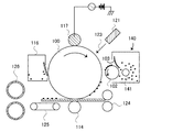


Abstract
Description
本発明は電子写真法、静電記録法、磁気記録法などに用いられるトナーに関するものである。 The present invention relates to a toner used in electrophotography, electrostatic recording, magnetic recording, and the like.
従来、電子写真方式においては、一般に光導電性物質よりなる静電潜像担持体(以下、感光体ともいう)を種々の手段で帯電し、さらに露光することにより感光体表面に静電潜像を形成する。次いで静電潜像をトナー担持体(以下、現像スリーブともいう)上のトナーで現像してトナー画像を形成し、紙の如き転写材にトナー画像を転写した後、熱、圧力、加熱加圧により転写材上にトナー画像を定着して複写物又はプリントを得るものである。この際、転写後に転写材に転写せずに感光体上に残余したトナーは種々の方法でクリーニングされ、上述の工程が繰り返される。 Conventionally, in an electrophotographic system, an electrostatic latent image carrier (hereinafter also referred to as a photoconductor) generally made of a photoconductive substance is charged by various means, and further exposed to an electrostatic latent image on the surface of the photoconductor. Form. Next, the electrostatic latent image is developed with toner on a toner carrier (hereinafter also referred to as a developing sleeve) to form a toner image, and the toner image is transferred to a transfer material such as paper, and then heat, pressure, and heat and pressure are applied. By fixing the toner image on the transfer material, a copy or print is obtained. At this time, the toner remaining on the photoreceptor without being transferred to the transfer material after the transfer is cleaned by various methods, and the above-described steps are repeated.
近年、電子写真法を用いた複写装置やプリンタはより高速化、高画質化、小型化が求められており、装置のプロセススピードは加速する一方で高精細画像を提供しなければならない。しかし、高速化によってトナーへの負荷は大きくなり、トナーの劣化に起因した画像濃度の低下等の現像性能に関する問題が起こりやすい。
一方、小型化の点においては、現像スリーブの小径化が重要な技術となる。トナーへの電荷付与は、主としてトナー規制部材(以下、現像ブレードという)によってトナーが規制された領域において、トナーと現像スリーブ等の摩擦帯電付与部材との摺擦に起因する摩擦帯電によって行なわれる。
In recent years, copying apparatuses and printers using electrophotography have been required to have higher speed, higher image quality, and smaller size, and it has been necessary to provide high-definition images while accelerating the process speed of the apparatus. However, the increase in the load increases the load on the toner, and problems with development performance such as a decrease in image density due to toner deterioration tend to occur.
On the other hand, reducing the diameter of the developing sleeve is an important technique in terms of downsizing. Charging of toner is performed mainly by frictional charging caused by friction between the toner and a frictional charging applying member such as a developing sleeve in a region where the toner is regulated by a toner regulating member (hereinafter referred to as a developing blade).
特に、上記のような小径化された現像スリーブの場合には、現像ニップ部の現像領域が狭くなることにより、現像スリーブからトナーが飛翔しにくくなる。このため、一部のトナーのみが過剰に帯電する、所謂チャージアップという現象が起こり、さまざまな画像欠陥を引き起こす場合がある。
例えば、トナーのチャージアップにより、トナーが現像スリーブに留まることで画像濃度が低下したり、トナーの帯電が不均一になることでかぶりといった画像欠陥が起こったりする場合がある。「かぶり」とは本来白抜けとなるべき非画像部にトナーが付着して濃度が高くなる現象を意味する。
また、チャージアップに起因する画像欠陥として、高温高湿環境においてベタ黒画像を出力すると、感光体にトナーが貼りついてしまい、トナーが転写材に効率的に転写されず、ベタ黒画像が白くぼやけてしまう画像弊害が発生する(以下、転写抜けという)。
In particular, in the case of the developing sleeve having a reduced diameter as described above, the developing area of the developing nip portion is narrowed, so that it is difficult for the toner to fly from the developing sleeve. For this reason, a phenomenon called so-called charge-up occurs in which only a part of the toner is excessively charged, which may cause various image defects.
For example, when the toner is charged up, the image density may be lowered due to the toner staying on the developing sleeve, or image defects such as fogging may occur due to uneven charging of the toner. The “fogging” means a phenomenon in which toner adheres to a non-image portion that should originally be white and the density increases.
In addition, if a solid black image is output in a high-temperature and high-humidity environment as an image defect caused by charge-up, the toner sticks to the photoreceptor, and the toner is not efficiently transferred to the transfer material, and the solid black image is blurred white. This will cause an adverse effect on the image (hereinafter referred to as transfer omission).
高温高湿環境で、転写抜けが発生する理由については以下の通りである。
転写材の電気的な体積抵抗値(以下、体積抵抗値という)は種々であり、特に高温高湿環境下では、転写材が水分を吸湿すると体積抵抗値は低くなり、吸湿していないと体積抵抗値は高くなる傾向にある。
しかし、吸湿紙などの体積抵抗値の低い転写材に対しては、転写材を介して紙搬送の上流に搬送をガイドする転写前ガイド部材や定着器などの本体へ転写電流が逃げてしまい、転写電流不足に起因する転写抜けが発生する場合がある。逆に体積抵抗値の低い転写材の電流の逃げを考慮して転写電流を高めに設定した場合、吸湿してない紙のように体積抵抗値の高い転写材では転写電流過多に起因する画像弊害が発生してしまう。特にトナーの耐久劣化が促進されてしまう耐久使用後半では、トナーの帯電が落ちる傾向にあり、このような転写抜けが顕著に現れてしまう。
そのため、転写電流が低い状態であっても、吸湿紙のような体積抵抗値の低い転写材で効率的に転写できるトナーが好ましい。
The reason why transfer loss occurs in a high temperature and high humidity environment is as follows.
There are various electric volume resistance values (hereinafter referred to as volume resistance values) of the transfer material. In particular, in a high-temperature and high-humidity environment, the volume resistance value decreases when the transfer material absorbs moisture. The resistance value tends to increase.
However, for transfer materials with low volume resistance such as moisture-absorbing paper, the transfer current escapes to the body such as a pre-transfer guide member or a fixing device that guides the conveyance upstream of the paper conveyance via the transfer material, In some cases, transfer omission due to insufficient transfer current may occur. On the other hand, if the transfer current is set to a high value in consideration of the current escape of the transfer material with a low volume resistance value, the transfer effect of the transfer material with a high volume resistance value, such as paper that has not absorbed moisture, is caused by an excessive transfer current. Will occur. In particular, in the latter half of durable use in which the durability deterioration of the toner is promoted, the charge of the toner tends to drop, and such transfer omission appears remarkably.
Therefore, a toner that can be efficiently transferred with a transfer material having a low volume resistance value such as moisture-absorbing paper is preferable even when the transfer current is low.
転写性を良化させる手段として、トナー粒子中に無機微粉体を外添するなどといった様々な手法(特許文献1〜3)が提案されている。特許文献1では、シロキサン結合したシラン縮合物を表面に存在させた酸化チタンをトナー母体粒子に外添することが開示されている。特許文献2では、針状の酸化チタンなどの外添剤の遊離率とトナー粒子表面の被覆率を制御することが開示されている。特許文献3では、トナーの飽和含水率を制御し、疎水化度が制御された外添剤を添加し、被覆率を制御することが開示されている。
As means for improving transferability, various methods (
これらの技術は確かに転写性にある一定の効果があるものの、上述のように現像スリーブを小径化した場合やより厳しい高温高湿環境での耐久使用後半においては、課題解決には至らず、依然として改善の余地があった。 Although these technologies certainly have a certain effect on transferability, the problem is not solved in the case where the diameter of the developing sleeve is reduced as described above or in the latter half of durable use in a severer high temperature and high humidity environment, There was still room for improvement.
本発明の目的は、上記の如き問題点を解決できるトナーを提供することにある。
具体的には、使用環境によらず安定した画像濃度と、かぶりのない良好な画像が得られるトナーであり、画像形成装置の小型化及び厳しい耐久試験(繰り返し使用試験)においても、転写抜けの発生を抑制できるトナーを提供することにある。
An object of the present invention is to provide a toner capable of solving the above problems.
Specifically, it is a toner that can provide a stable image density and a good image without fog regardless of the use environment. Even in the downsizing of an image forming apparatus and severe endurance tests (repeated use tests), there is no transfer omission. An object of the present invention is to provide a toner capable of suppressing the generation.
本発明者らは、特定形状の酸化チタン微粒子及びシリカ微粒子のトナーへの外添状態を規定することにより、課題を解決しうることを見出し、本発明の完成に至った。すなわち、本発明は、以下のとおりである。
結着樹脂及び着色剤を含有するトナー粒子と、
外添剤としての、酸化チタン微粒子及びシリカ微粒子と、
を有するトナーであって、
前記酸化チタン微粒子は、
長軸径が30nm以上500nm以下であり、
短軸径が10nm以上80nm以下であり、
長軸径/短軸径の比が2.0以上8.0以下である
ルチル型の酸化チタン微粒子であり、
前記酸化チタン微粒子の含有量が、前記トナー粒子100質量部当たり0.1質量部以上1.0質量部以下であり、
前記トナー中の、前記酸化チタン微粒子の含有量に対する前記シリカ微粒子の含有量の比が、0.4以上30.0以下であり
X線光電子分光装置(ESCA)により求めた、前記トナー粒子の表面の前記シリカ微粒子による被覆率X1が、40.0面積%以上75.0面積%以下であり、
前記シリカ微粒子による理論被覆率をX2としたとき、下記式1で示される拡散指数が、下記式2を満たし、
前記トナー粒子への前記外添剤の埋め込み率が、25%以上60%以下である
ことを特徴とするトナー。
(式1)拡散指数=X1/X2
(式2)拡散指数≧−0.0042×X1+0.62
The present inventors have found that the problem can be solved by defining the externally added state of titanium oxide fine particles and silica fine particles having specific shapes to the toner, and the present invention has been completed. That is, the present invention is as follows.
Toner particles containing a binder resin and a colorant;
Titanium oxide fine particles and silica fine particles as external additives,
A toner having
The titanium oxide fine particles are:
The major axis diameter is 30 nm or more and 500 nm or less,
The minor axis diameter is 10 nm or more and 80 nm or less,
Rutile-type titanium oxide fine particles having a major axis diameter / minor axis diameter ratio of 2.0 or more and 8.0 or less,
The titanium oxide fine particle content is 0.1 parts by mass or more and 1.0 part by mass or less per 100 parts by mass of the toner particles,
The ratio of the content of the silica fine particles to the content of the titanium oxide fine particles in the toner is 0.4 or more and 30.0 or less, and the surface of the toner particles obtained by an X-ray photoelectron spectrometer (ESCA) The coverage X1 by the silica fine particles is 40.0 area% or more and 75.0 area% or less,
When the theoretical coverage by the silica fine particles is X2, the diffusion index represented by the following
The toner according to
(Formula 1) Diffusion index = X1 / X2
(Expression 2) Diffusion index ≧ −0.0042 × X1 + 0.62
本発明によれば、使用環境によらず安定した画像濃度と、かぶりのない良好な画像が得られるトナーであり、画像形成装置の小型化及び厳しい耐久試験においても、転写抜けの発生を抑制できるトナーを提供することが可能である。 According to the present invention, it is a toner capable of obtaining a stable image density and a good image without fog regardless of the use environment, and can suppress the occurrence of transfer omission even in downsizing of an image forming apparatus and severe durability test. It is possible to provide toner.
以下、本発明の実施形態について説明する。本発明のトナーは、
結着樹脂及び着色剤を含有するトナー粒子と、
外添剤としての、酸化チタン微粒子及びシリカ微粒子と、
を有するトナーであって、
前記酸化チタン微粒子は、
長軸径が30nm以上500nm以下であり、
短軸径が10nm以上80nm以下であり、
長軸径/短軸径の比が2.0以上8.0以下である
ルチル型の酸化チタン微粒子であり、
前記酸化チタン微粒子の含有量が、前記トナー粒子100質量部当たり0.1質量部以上1.0質量部以下であり、
前記トナー中の、前記酸化チタン微粒子の含有量に対する前記シリカ微粒子の含有量の比が0.4以上30.0以下であり、
X線光電子分光装置(ESCA)により求めた、前記トナー粒子の表面の前記シリカ微粒子による被覆率X1が、40.0面積%以上75.0面積%以下であり、
前記シリカ微粒子による理論被覆率をX2としたとき、下記式1で示される拡散指数が下記式2を満たし、
前記トナー粒子への前記外添剤の埋め込み率が25%以上60%以下である
ことを特徴とするトナーである。
(式1)拡散指数=X1/X2
(式2)拡散指数≧−0.0042×X1+0.62
Hereinafter, embodiments of the present invention will be described. The toner of the present invention is
Toner particles containing a binder resin and a colorant;
Titanium oxide fine particles and silica fine particles as external additives,
A toner having
The titanium oxide fine particles are:
The major axis diameter is 30 nm or more and 500 nm or less,
The minor axis diameter is 10 nm or more and 80 nm or less,
Rutile-type titanium oxide fine particles having a major axis diameter / minor axis diameter ratio of 2.0 or more and 8.0 or less,
The titanium oxide fine particle content is 0.1 parts by mass or more and 1.0 part by mass or less per 100 parts by mass of the toner particles,
The ratio of the content of the silica fine particles to the content of the titanium oxide fine particles in the toner is 0.4 or more and 30.0 or less,
The coverage X1 with the silica fine particles on the surface of the toner particles determined by an X-ray photoelectron spectrometer (ESCA) is 40.0 area% or more and 75.0 area% or less,
When the theoretical coverage by the silica fine particles is X2, the diffusion index represented by the following
The toner is characterized in that the embedding rate of the external additive in the toner particles is 25% or more and 60% or less.
(Formula 1) Diffusion index = X1 / X2
(Expression 2) Diffusion index ≧ −0.0042 × X1 + 0.62
本発明者らの検討によれば、上記のようなトナーを用いることにより、使用環境によらず安定した画像濃度と、かぶりのない良好な画像が得られるトナーであり、画像形成装置の小型化及び厳しい耐久試験においても、転写抜けの発生を抑制できる。
ここで、転写抜けの問題は以下の原因により発生すると考えている。
According to the study by the present inventors, by using the toner as described above, it is a toner that can obtain a stable image density regardless of the use environment and a good image without fogging, and downsizing the image forming apparatus. In addition, the occurrence of transfer omission can be suppressed even in a severe durability test.
Here, it is considered that the problem of transfer omission occurs due to the following causes.
現像スリーブと現像ブレードの摺擦が行われる領域を、ブレードニップという。長期の耐久試験により、トナーはブレードニップにおける摺擦によりストレスを受け、外添剤が埋めこまれることで、耐久初期と耐久後期で流動性等のトナー物性変化が異なる、「トナー劣化」が生じる。また、小型化に対応して、現像スリーブを小径化した場合には、チャージアップしたトナーが生じやすく、帯電が不均一になりやすい。
これにより、例えば、非画像領域へのかぶりといった画像欠陥を引き起こしやすくなるだけでなく、トナーと他の部材との付着力が高まることによる、様々な問題が発生しやすくなる。例えば、チャージアップしたトナーが現像スリーブ上に留まることにより、画像濃度が低下しやすくなる。
A region where the developing sleeve and the developing blade are rubbed is referred to as a blade nip. According to a long-term durability test, the toner is stressed by rubbing at the blade nip, and the external additive is embedded, resulting in a change in toner physical properties such as fluidity in the early and late durability, resulting in "toner deterioration". . Further, when the developing sleeve is reduced in size in response to downsizing, charged-up toner is likely to be generated, and charging is likely to be uneven.
As a result, for example, not only image defects such as fogging on non-image areas are likely to occur, but also various problems are likely to occur due to increased adhesion between the toner and other members. For example, when the charged-up toner stays on the developing sleeve, the image density tends to decrease.
また、上述のように、長期耐久により、ストレスを受けて劣化したトナーは、流動性が悪いため、ブレードニップ内での循環性が悪く、トナー全体が適正に摩擦帯電されにくい。このとき、チャージアップしたトナーは、感光体との付着力が高まる傾向にある。さらに高温高湿環境で吸湿紙といった体積抵抗値の低い転写材に対して画像出力を行う場合は、転写電流が逃げてしまうためトナーが非常に転写されにくく、転写抜けが発生してしまう。 In addition, as described above, the toner deteriorated by stress due to long-term durability has poor fluidity, and therefore poor circulation in the blade nip, and the entire toner is not easily frictionally charged. At this time, the charged-up toner tends to increase the adhesion force with the photoreceptor. Further, when image output is performed on a transfer material having a low volume resistance value such as moisture-absorbing paper in a high-temperature and high-humidity environment, the transfer current escapes, so the toner is very difficult to transfer, and transfer omission occurs.
こういった問題を引き起こさないためには、トナーの劣化を抑制し、同時にチャージアップを抑制し、なおかつ感光体とトナーの付着力を低減することが重要である。そのためには、まず、外添剤としてシリカ微粒子を含有し、被覆率X1を40.0面積%以上75.0面積%以下とすることが重要である。さらに、理論被覆率X2としたとき、拡散指数(=X1/X2)を特定の範囲に制御することが重要である。 In order not to cause such problems, it is important to suppress the deterioration of the toner, at the same time, suppress the charge-up, and reduce the adhesion between the photosensitive member and the toner. For this purpose, it is important to first contain silica fine particles as an external additive and to make the coverage X1 40.0 area% or more and 75.0 area% or less. Furthermore, when the theoretical coverage ratio X2 is set, it is important to control the diffusion index (= X1 / X2) within a specific range.
シリカ微粒子の一次粒子の個数平均粒径は、好ましくは5nm以上20nm以下であり、より好ましくは5nm以上15nm以下であり、さらに好ましくは7nm以上15nm以下である。
被覆率X1は、好ましくは、45.0面積%以上70.0面積%以下であり、より好ましくは、45.0面積%以上68.0面積%以下である。
ここで、被覆率X1が40.0面積%未満のとき、本発明の意図する効果が得られない。一方、被覆率X1が75.0面積%を超える場合には、低温定着性を阻害する場合がある。
上記のように被覆率X1と拡散指数を制御することにより、トナーの長期耐久使用に起因するトナー劣化を大幅に抑制することが可能である。
The number average particle diameter of primary particles of silica fine particles is preferably 5 nm or more and 20 nm or less, more preferably 5 nm or more and 15 nm or less, and further preferably 7 nm or more and 15 nm or less.
The coverage X1 is preferably 45.0 area% or more and 70.0 area% or less, and more preferably 45.0 area% or more and 68.0 area% or less.
Here, when the coverage X1 is less than 40.0 area%, the intended effect of the present invention cannot be obtained. On the other hand, when the coverage X1 exceeds 75.0 area%, the low-temperature fixability may be hindered.
By controlling the coverage X1 and the diffusion index as described above, it is possible to greatly suppress toner deterioration caused by long-term use of the toner.
シリカ微粒子の一次粒径が比較的小さく、一次粒子の個数平均粒径が5nm未満となると、シリカ微粒子同士が凝集しやすく、トナー粒子表面においても、凝集体として存在しやすい。シリカ微粒子が凝集体で存在する場合、耐久使用試験を重ねると、トナー同士の摺擦により、シリカ微粒子が解されることにより、トナー粒子表面から脱離しやすい。
そのため、耐久使用初期に被覆率X1を調整するようにシリカ微粒子を添加しても、耐久使用後期にはシリカ微粒子による被覆率が低下しやすい。さらに凝集体であることにより、シリカ微粒子同士の力によりトナーにシリカ微粒子がより多く埋めこまれやすく、耐久使用初期と耐久使用後期のトナー物性が大きく異なりやすく、トナー劣化を引き起こしやすい。
When the primary particle size of the silica fine particles is relatively small and the number average particle size of the primary particles is less than 5 nm, the silica fine particles are likely to aggregate with each other and also exist as aggregates on the toner particle surface. When the silica fine particles are present as an aggregate, when the durability use test is repeated, the silica fine particles are easily released from the surface of the toner particles due to the rubbing between the toners.
Therefore, even if silica fine particles are added so as to adjust the coverage X1 in the early stage of durable use, the coverage by the silica fine particles tends to decrease in the latter half of durable use. Further, since the aggregate is used, the silica particles are more likely to be embedded in the toner due to the force between the silica particles, and the toner physical properties at the initial stage of durable use and the late stage of durable use are likely to be greatly different and toner deterioration is likely to occur.
一方、本発明では、被覆率X1と拡散指数を同時に制御することにより、トナー粒子表面にシリカ微粒子を、高度に均一拡散させることが可能である。
この場合、シリカ微粒子がより一次粒子に近い状態でトナー粒子表面に付着しているため、耐久使用試験を行っても、トナー粒子表面からシリカ微粒子が脱離しにくい。また、シリカ微粒子がより一次粒子に近い状態であるため、シリカ微粒子同士が接触する確率が低くなるとともに、シリカ微粒子同士の力でトナー粒子に埋めこまれやすくなることも抑制することが可能である。
On the other hand, in the present invention, the silica fine particles can be highly uniformly diffused on the surface of the toner particles by simultaneously controlling the coverage X1 and the diffusion index.
In this case, since the silica fine particles are attached to the surface of the toner particles in a state closer to the primary particles, the silica fine particles are hardly detached from the surface of the toner particles even in the durability use test. Further, since the silica fine particles are in a state closer to the primary particles, the probability that the silica fine particles are in contact with each other is reduced, and it is possible to suppress the toner particles from being easily embedded in the toner particles. .
また、本発明においては、トナー粒子への外添剤の埋め込み率が25%以上60%以下であることが、重要である。好ましくは、30%以上55%以下である。上述のように、被覆率と拡散指数を制御するとともに、埋め込み率を上記範囲とすることで、初めて感光体とトナーの付着力を低減することができる。 In the present invention, it is important that the external additive embedding rate in the toner particles is 25% or more and 60% or less. Preferably, it is 30% or more and 55% or less. As described above, by controlling the coverage and the diffusion index and setting the embedding rate within the above range, the adhesion between the photosensitive member and the toner can be reduced for the first time.
この理由は定かではないが、本発明者らは次のように考えている。
感光体とトナーの付着力を低減するには、感光体とトナー粒子の間に、無機微粒子である外添剤が介在することが非常に重要となる。上述のように、高度に均一拡散した外添剤が、ある特定の状態で埋めこまれていることにより、トナー粒子表面の状態がより均一化されると考えられる。その結果、トナーと感光体が接触した際に、外添剤が介在する確率を最大限に高くできるため、トナーと感光体の付着力が低減できると考えられる。
The reason for this is not clear, but the present inventors consider as follows.
In order to reduce the adhesion between the photoconductor and the toner, it is very important that an external additive which is an inorganic fine particle is interposed between the photoconductor and the toner particles. As described above, it is considered that the state of the toner particle surface is made more uniform by embedding the external additive highly uniformly diffused in a specific state. As a result, it is considered that the adhesion between the toner and the photoconductor can be reduced because the probability that the external additive intervenes when the toner and the photoconductor are in contact with each other can be maximized.
例えば、凝集体の状態で埋め込み率だけを制御したとしても、凝集体の一部の外添剤は完全に埋没していたり、またある一部の外添剤は全く埋没せずに存在していたりすることになる。
すると、埋没していない部分がトナー粒子表面で動くなどして、外添剤の付着していない部分が露出し、感光体と直接接触することになる確率が高くなる。その結果、感光体とトナーの付着力を低減させることができない。
For example, even if only the embedding rate is controlled in the state of an aggregate, some external additives in the aggregate are completely buried or some external additives are not buried at all. Will be.
As a result, the portion that is not buried moves on the surface of the toner particles, and the portion where the external additive is not attached is exposed, so that the probability that the portion is not in direct contact with the photoreceptor increases. As a result, the adhesion between the photoconductor and the toner cannot be reduced.
一方、本発明のように、一定以上の被覆率を有し、拡散指数を制御した状態だとしても、外添剤の埋め込み率が25%未満の場合、耐久使用試験において、トナーにシェアがかかると、外添剤が脱離しやすく、感光体とトナー粒子が直接接触する部分が出やすい。
逆に、外添剤の埋め込み率が60%を超える場合は、トナーの循環性が低下しやすく、一度、トナー粒子と感光体が直接接触する部分があった場合にはトナーが回転せずに、外添剤が介在することができずに、感光体からトナーが離れにくい場合がある。
被覆率と拡散指数については後に詳述する。
On the other hand, as in the present invention, even when the covering ratio is above a certain level and the diffusion index is controlled, if the embedding ratio of the external additive is less than 25%, the share of the toner is applied in the durability use test. As a result, the external additive is easily detached, and a portion where the photoreceptor and the toner particles are in direct contact is likely to appear.
On the contrary, when the embedding rate of the external additive exceeds 60%, the circulation property of the toner tends to be lowered, and once there is a portion where the toner particles and the photoreceptor are in direct contact, the toner does not rotate. In some cases, the external additive cannot intervene and it is difficult to separate the toner from the photoreceptor.
The coverage and diffusion index will be described in detail later.
また、本発明のトナーは、酸化チタン微粒子を含有し、その酸化チタン微粒子がルチル型構造であり、長軸径及び短軸径が特定の範囲であることが重要である。
本発明者らは、シリカ微粒子が高度に均一拡散した状態で、特定の構造および形状の酸化チタン微粒子を添加することで、トナー粒子表面において、酸化チタン微粒子も高度に均一拡散させることが可能であることを見出した。その結果、酸化チタン微粒子によるトナーのチャージアップ抑制効果を十分に発揮させることでき、トナーと感光体との付着力を低減させることができ、高温高湿環境下における吸湿紙での転写抜け抑制に顕著な効果を得られることを同時に見出した。
特に、シリカ微粒子が凝集体の状態だと、酸化チタン微粒子の周りにシリカ微粒子が付着するなどして、トナーのチャージアップ抑制効果を十分に発揮しにくい。
Further, it is important that the toner of the present invention contains fine titanium oxide particles, the fine titanium oxide particles have a rutile structure, and the major axis diameter and minor axis diameter are in a specific range.
By adding titanium oxide fine particles having a specific structure and shape in a state where silica fine particles are highly uniformly diffused, the present inventors can highly uniformly diffuse titanium oxide fine particles on the toner particle surface. I found out. As a result, the effect of suppressing the charge-up of the toner by the titanium oxide fine particles can be sufficiently exerted, the adhesion force between the toner and the photoreceptor can be reduced, and the transfer omission on the absorbent paper can be suppressed in a high temperature and high humidity environment. At the same time, it was found that remarkable effects can be obtained.
In particular, when the silica fine particles are in an aggregated state, the silica fine particles adhere around the titanium oxide fine particles, and thus it is difficult to sufficiently exert the toner charge-up suppressing effect.
上記のように、2種類の無機微粒子を高度に均一拡散させることにより、酸化チタン微粒子がトナー粒子表面に高度に均一拡散した状態で付着するため、チャージアップを効果的に抑制することができる。
すると、例えば、現像スリーブを小径化し、高温高湿環境下の長期耐久使用後に吸湿紙などの体積抵抗値が低い転写材を用いた画像形成においても、トナー全体にチャージを適正に持たせることが可能になり、転写抜けを抑制することができる。この場合、チャージアップ抑制効果を十分に発揮することができ、トナーのチャージアップに起因する問題を抑制することができる。
As described above, by highly uniformly diffusing the two types of inorganic fine particles, the titanium oxide fine particles adhere to the surface of the toner particles in a highly uniformly diffused state, so that charge-up can be effectively suppressed.
Then, for example, even in image formation using a transfer material having a low volume resistance value such as moisture absorbent paper after long-term durability use in a high-temperature and high-humidity environment, the toner can be appropriately charged throughout the developing sleeve. And transfer omission can be suppressed. In this case, the effect of suppressing the charge-up can be sufficiently exhibited, and problems caused by the charge-up of the toner can be suppressed.
被覆率と拡散指数、及び外添剤の埋め込み率を同時に制御することにより、トナーの劣化を抑制し、同時にチャージアップを抑制し、なおかつ感光体とトナーの付着力を低減することができ、課題を解決することが初めて可能となる。
本発明において、酸化チタン微粒子は、長軸径が30nm以上500nm以下であり、短軸径が10nm以上80nm以下であり、長軸径/短軸径の比が2.0以上8.0以下であることが重要である。長軸径は好ましくは30nm以上300nm以下であり、より好ましくは30nm以上150nm以下である。短軸径は、好ましくは10nm以上50nm以下である。長軸径/短軸径の比は好ましくは2.5以上8.0以下である。
この範囲であることにより、酸化チタン微粒子が耐久使用試験においてもトナーに埋め込まれにくいため、耐久使用後半においてもチャージアップ抑制効果が得られやすい。
By simultaneously controlling the coverage ratio, diffusion index, and external additive embedding ratio, it is possible to suppress toner deterioration, simultaneously suppress charge-up, and reduce the adhesion between the photoreceptor and the toner. For the first time.
In the present invention, the titanium oxide fine particles have a major axis diameter of 30 nm or more and 500 nm or less, a minor axis diameter of 10 nm or more and 80 nm or less, and a ratio of major axis diameter / minor axis diameter of 2.0 or more and 8.0 or less. It is important to be. The major axis diameter is preferably 30 nm to 300 nm, more preferably 30 nm to 150 nm. The minor axis diameter is preferably 10 nm or more and 50 nm or less. The ratio of major axis diameter / minor axis diameter is preferably 2.5 or more and 8.0 or less.
By being in this range, since the titanium oxide fine particles are not easily embedded in the toner even in the durability use test, the charge-up suppressing effect is easily obtained even in the latter half of the durability use.
長軸径が30nm未満又は短軸径が10nm未満の場合、酸化チタン微粒子がトナーに埋め込まれやすくなり、スペーサー効果が発揮しにくくなり、耐久使用後半での転写抜け抑制の効果が得られにくい。
また、長軸径が500nm超又は短軸径が80nm超の場合、トナーから酸化チタン微粒子の遊離が顕著になり、十分なチャージアップ抑制の効果が得られにくい。
長軸径/短軸径の比が2.0よりも小さい場合は、球状に近くなるためにトナー粒子との接触面積が小さく、トナーの付着性の効果が少なりやすく、トナーから遊離しやすくなる。
一方、長軸径/短軸径の比が8.0よりも大きい場合、酸化チタン微粒子の形状が極端に棒型や針状になり、トナーや他の外添剤との接触面積が大きくなってスペーサー効果が小さくなりやすく、耐久性が悪化しやすい。
When the major axis diameter is less than 30 nm or the minor axis diameter is less than 10 nm, the titanium oxide fine particles are easily embedded in the toner, the spacer effect is hardly exhibited, and the effect of suppressing transfer omission in the latter half of the endurance use is hardly obtained.
Further, when the major axis diameter exceeds 500 nm or the minor axis diameter exceeds 80 nm, the release of titanium oxide fine particles from the toner becomes remarkable, and it is difficult to obtain a sufficient charge-up suppressing effect.
When the ratio of the major axis diameter / minor axis diameter is smaller than 2.0, the contact area with the toner particles is small because it is nearly spherical, and the effect of adhesion of the toner tends to be small, and it is easy to release from the toner. Become.
On the other hand, when the ratio of the major axis diameter / minor axis diameter is larger than 8.0, the shape of the titanium oxide fine particles becomes extremely rod-shaped or needle-shaped, and the contact area with the toner or other external additives becomes large. As a result, the spacer effect tends to be small and the durability tends to deteriorate.
本発明において、酸化チタン微粒子はルチル型であることが重要である。
酸化チタンとしては、結晶系がルチル型とアナターゼ型のものがある。このうち、アナターゼ型の酸化チタンは体積抵抗値が107Ω・cm程度と一般的に低いため、特に高温高湿環境下では、摩擦帯電のリークが早くなりやすく、摩擦帯電安定化の面で十分ではない。これに対してルチル型酸化チタンは、体積抵抗値が1010Ω・cm〜1018Ω・cm程度と高いため、摩擦帯電量の安定化の面で極めて有効に働く。
In the present invention, it is important that the titanium oxide fine particles are of the rutile type.
Titanium oxide includes a rutile type and an anatase type crystal system. Of these, anatase-type titanium oxide has a volume resistance of about 10 7 Ω · cm, which is generally low. Therefore, especially in a high-temperature and high-humidity environment, the leakage of triboelectric charge tends to be quick, and in terms of stabilizing triboelectric charging. Not enough. Rutile titanium oxide contrast, since the volume resistivity is as high as about 10 10 Ω · cm~10 18 Ω · cm, acts very effectively in terms of stabilizing the triboelectric charge quantity.
なお、一般に、酸化チタンは、X線回折において、いくつかのピークを持つことが知られている。酸化チタンの結晶系がアナターゼ型の場合には2θ=25.3付近に、ルチル型の場合には2θ=27.5付近に、特徴的で大きなピークを持つことが知られており、これにより識別が可能である。
本発明において使用するルチル型の酸化チタン微粒子の原材料及び製造方法は、特に制約されるものではないが、以下に製造例を示す。
In general, titanium oxide is known to have several peaks in X-ray diffraction. It is known that when the titanium oxide crystal system is anatase type, it has a characteristic and large peak around 2θ = 25.3, and when it is rutile type, it has a characteristic big peak around 2θ = 27.5. Identification is possible.
Although the raw material and manufacturing method of the rutile-type titanium oxide fine particles used in the present invention are not particularly limited, manufacturing examples are shown below.
イルメナイトを出発原料として、これを硫酸で分解して得られた分散液を加水分解することによって、スラリー状のメタチタン酸を生成する。このメタチタン酸のスラリーのpH調整後、濾過、焼成、解砕して酸化チタンを得る。得られた酸化チタンを溶液中に分散させながら疎水化剤を滴下混合し反応させる。これを、濾過、加熱処理、解砕処理を行うことによって、ルチル型の酸化チタンを得ることができる。 Slurry metatitanic acid is produced by hydrolyzing a dispersion obtained by using ilmenite as a starting material and decomposing it with sulfuric acid. After adjusting the pH of this metatitanic acid slurry, it is filtered, fired and crushed to obtain titanium oxide. While dispersing the obtained titanium oxide in the solution, a hydrophobizing agent is added dropwise and reacted. A rutile type titanium oxide can be obtained by performing a filtration, a heat processing, and a crushing process for this.
ルチル型の酸化チタン微粒子は、その表面が疎水化処理剤で処理されていることが好ましい。本発明に好ましく使用できる疎水化処理剤としては、シリコーンオイル、シリコーンワニスがある。中でもシランカップリング剤、或いはメチルハイドロジェンタイプのシリコーンオイルの如き自己架橋性のあるものが耐久安定性のためにも好ましい。 The surface of rutile-type titanium oxide fine particles is preferably treated with a hydrophobizing agent. Examples of the hydrophobic treatment agent that can be preferably used in the present invention include silicone oil and silicone varnish. Among them, a silane coupling agent or a self-crosslinking agent such as methyl hydrogen type silicone oil is preferable for durability stability.
特に好ましく用いられるのはシランカップリング剤であり、一般式 RmSiYn
R:アルコキシ基
M:1〜3の整数
Y:アルキル基、ビニル基、グリシドキシ基、メタクリル基を含む炭化水素基
N:1〜3の整数
で表されるものであり、例えば以下のものが挙げられる。ビニルトリメトキシシラン、ビニルトリエトキシシラン、γ−メタクリルオキシプロピルトリメトキシシラン、ビニルトリアセトキシシラン、メチルトリメトキシシラン、メチルトリエトキシシラン、イソブチルトリメトキシシラン、ジメチルジメトキシシラン、ジメチルジエトキシシラン、トリメチルメトキシシラン、ヒドロキシプロピルトリメトキシシラン、フェニルトリメトキシシラン、n−ヘキサデシルトリメトキシシラン、n−オクタデシルトリメトキシシラン、オクチルトリメトキシシラン、オクチルトリエトキシシランの如きシランカップリング剤。
Particularly preferably used is a silane coupling agent, which has the general formula RmSiYn.
R: alkoxy group
M: integer from 1 to 3
Y: hydrocarbon group including alkyl group, vinyl group, glycidoxy group, methacryl group N: an integer of 1 to 3
For example, the following may be mentioned. Vinyltrimethoxysilane, vinyltriethoxysilane, γ-methacryloxypropyltrimethoxysilane, vinyltriacetoxysilane, methyltrimethoxysilane, methyltriethoxysilane, isobutyltrimethoxysilane, dimethyldimethoxysilane, dimethyldiethoxysilane, trimethylmethoxy Silane coupling agents such as silane, hydroxypropyltrimethoxysilane, phenyltrimethoxysilane, n-hexadecyltrimethoxysilane, n-octadecyltrimethoxysilane, octyltrimethoxysilane, octyltriethoxysilane.
疎水化処理剤の処理量は、酸化チタン微粒子100質量部に対して1質量部〜50質量部、好ましくは3質量部〜40質量部とし、疎水化度を20%〜98%、好ましくは30%〜90%、より好ましくは40%〜80%にすれば良い。
疎水化度が20%未満の場合、高温高湿環境下での長期静置に起因する帯電量低下が大きくなり現像性の低下を招くことがある。また疎水化度が98%を超えると、酸化チタン自身の帯電コントロールが難しくなり、結果として低湿下でトナーがチャージアップしてしまう場合がある。
The treatment amount of the hydrophobizing agent is 1 part by mass to 50 parts by mass, preferably 3 parts by mass to 40 parts by mass with respect to 100 parts by mass of the titanium oxide fine particles, and the degree of hydrophobicity is 20% to 98%, preferably 30. % To 90%, more preferably 40% to 80%.
When the degree of hydrophobicity is less than 20%, the decrease in charge amount due to long-term standing in a high-temperature and high-humidity environment becomes large, which may lead to a decrease in developability. On the other hand, if the degree of hydrophobicity exceeds 98%, it becomes difficult to control the charge of titanium oxide itself, and as a result, the toner may be charged up under low humidity.
また、本発明においては、酸化チタン微粒子をトナー100質量部当り0.1質量部以上1.0質量部以下含有することが重要である。より好ましくは、0.1質量部以上0.6質量部である。
0.1質量部より少ない場合は、チャージアップ抑制の効果が十分に得にくく、特に耐久による転写悪化を抑制しづらい。1.0質量部よりも多い場合は、トナー粒子から遊離したものが多くなることによる部材汚染が発生しやすく、また低温定着性が低下する場合がある。
In the present invention, it is important that the titanium oxide fine particles are contained in an amount of 0.1 to 1.0 part by mass per 100 parts by mass of the toner. More preferably, it is 0.1 to 0.6 parts by mass.
When the amount is less than 0.1 parts by mass, it is difficult to sufficiently obtain the effect of suppressing the charge-up, and it is particularly difficult to suppress transfer deterioration due to durability. When the amount is more than 1.0 part by mass, contamination of the member due to an increase in the amount released from the toner particles tends to occur, and the low-temperature fixability may be lowered.
また、本発明においては、前記酸化チタン微粒子のトナー中の含有量に対する、前記シリカ微粒子の含有量の比が0.4以上30.0以下であることが重要である。より好ましくは、0.7以上20.0以下である。
シリカ微粒子の含有量の比が0.4より小さい場合は、酸化チタン微粒子がシリカ微粒子に対して過剰になってしまうため、外添剤による埋め込み率の制御がしづらくなってしまう。
また、シリカ微粒子の含有量の比が30.0より大きい場合は、酸化チタン微粒子がシリカ微粒子に対して少なくなりすぎてしまうため、チャージアップ抑制の効果が得られにくくなってしまう。
In the present invention, it is important that the ratio of the content of the silica fine particles to the content of the titanium oxide fine particles in the toner is 0.4 or more and 30.0 or less. More preferably, it is 0.7 or more and 20.0 or less.
When the content ratio of the silica fine particles is smaller than 0.4, the titanium oxide fine particles are excessive with respect to the silica fine particles, and thus it is difficult to control the embedding rate with the external additive.
On the other hand, when the content ratio of the silica fine particles is larger than 30.0, the titanium oxide fine particles are too small with respect to the silica fine particles, so that it is difficult to obtain the effect of suppressing the charge-up.
さらに、酸化チタン微粒子の遊離率は50%以下であることが好ましく、より好ましくは30%以下、さらに好ましくは20%以下であることの好ましい。遊離率がこの範囲であると、チャージアップ抑制効果が発揮しやすくなり、感光体との付着力低減の効果が得られやすい。なお、酸化チタン微粒子の遊離率の測定方法の詳細は後述するが、水溶液中で半ば強制的に遊離させたときの遊離率である。上述の外添剤の埋め込み率はシリカ微粒子と酸化チタン微粒子の両方の寄与となるので、酸化チタン微粒子の遊離率とは直接関係しない。
酸化チタン微粒子の遊離率を上記範囲に制御する手段としては、外添混合処理時の動力や処理時間の調整が挙げられる。外添混合処理時の動力を下げるか、処理時間を短くすることで、遊離率を高くすることができる。また、外添混合処理時の動力を上げるか、処理時間を長くすることで遊離率を低くすることができる。
Furthermore, the liberation rate of the titanium oxide fine particles is preferably 50% or less, more preferably 30% or less, and still more preferably 20% or less. When the liberation rate is within this range, the effect of suppressing the charge-up is easily exhibited, and the effect of reducing the adhesion force with the photoreceptor is easily obtained. In addition, although the detail of the measuring method of the release rate of titanium oxide microparticles | fine-particles is mentioned later, it is a release rate when it was made to forcibly release in aqueous solution halfway. The embedding rate of the external additive described above contributes to both the silica fine particles and the titanium oxide fine particles, and is not directly related to the release rate of the titanium oxide fine particles.
Examples of means for controlling the liberation rate of the titanium oxide fine particles within the above range include adjustment of power and treatment time during external addition mixing treatment. The rate of liberation can be increased by reducing the power during external addition or by shortening the treatment time. Moreover, the liberation rate can be lowered by increasing the power during the external addition mixing process or by increasing the processing time.
本発明においては、上述のように、被覆率と拡散指数を制御することで、トナー劣化を抑制することが可能であるが、例えば、トナーの充填量を増やすなどして、印字枚数を増加した場合は、トナーの劣化を引き起こす場合もある。
これまで述べてきたような均一帯電やチャージアップ抑制が、トナーが劣化した場合にも、適正に行われるためには、ブレードニップにおける摺擦が、耐久使用後期においても、トナー一粒一粒に行われるよう、トナーがほぐれやすいことが重要である。
この「トナーが劣化した際にも、トナーが一粒一粒にほぐれやすくなる現象」には、上述の被覆率及び拡散指数が密接に関係している。
In the present invention, as described above, it is possible to suppress toner deterioration by controlling the coverage and diffusion index. For example, the number of printed sheets is increased by increasing the amount of toner filling. In some cases, the toner may be deteriorated.
In order for the uniform charging and suppression of charge-up as described so far to be properly performed even when the toner deteriorates, the friction at the blade nip is reduced to a single toner even in the end of durable use. It is important that the toner be easily loosened as is done.
The above-described coverage and diffusion index are closely related to this “phenomenon in which the toner is easy to loosen one by one even when the toner deteriorates”.
次に、本発明のトナーは、「シリカ微粒子の外添状態」を以下のように規定する。
本発明のトナーは、X線光電子分光装置(ESCA)により求めた、トナー粒子の表面のシリカ微粒子による被覆率X1が40.0面積%以上75.0面積%以下である。さらに、シリカ微粒子による理論被覆率をX2としたとき、下記式1で示される拡散指数が下記式2を満足することを特徴とするトナーである。
(式1)拡散指数=X1/X2
(式2)拡散指数≧−0.0042×X1+0.62
Next, in the toner of the present invention, the “external addition state of silica fine particles” is defined as follows.
In the toner of the present invention, the coverage X1 with silica fine particles on the surface of the toner particles determined by an X-ray photoelectron spectrometer (ESCA) is 40.0 area% or more and 75.0 area% or less. Further, the toner is characterized in that the diffusion index represented by the following
(Formula 1) Diffusion index = X1 / X2
(Expression 2) Diffusion index ≧ −0.0042 × X1 + 0.62
上記被覆率X1は、シリカ微粒子単体をESCAで測定した時のSi元素の検出強度に対して、トナーを測定した時のSi元素の検出強度の比から、算出することができる。この被覆率X1は、トナー粒子表面のうち、シリカ微粒子が実際に被覆している面積の割合を示す。
被覆率X1が40.0面積%以上75.0面積%以下の場合、耐久使用試験を通じて、トナーの流動性及び帯電性を良好な状態に制御できる。被覆率X1が40.0面積%未満の場合、後述するトナーのほぐれ易さを十分に得ることができない。このため、評価条件や環境によっては、トナーが劣化しやすく、流動性が悪化する。
The coverage X1 can be calculated from the ratio of the Si element detection intensity when the toner is measured to the Si element detection intensity when the silica fine particle is measured by ESCA. The coverage X1 indicates the proportion of the area of the toner particle surface that is actually covered with silica fine particles.
When the coverage X1 is 40.0 area% or more and 75.0 area% or less, the fluidity and charging property of the toner can be controlled to be in a good state through the durability use test. When the coverage X1 is less than 40.0 area%, it is not possible to obtain sufficient ease of toner loosening described later. For this reason, depending on the evaluation conditions and environment, the toner is likely to deteriorate and the fluidity deteriorates.
一方、シリカ微粒子による理論被覆率X2は、トナー粒子100質量部あたりのシリカ微粒子の質量部数、及びシリカ微粒子の粒径等を用い、下記式4より算出される。これはトナー粒子表面を理論的に被覆できる面積の割合を示す。
(式4)理論被覆率x2(面積%)=31/2/(2Π)×(dT/dA)×(ρT/ρT)×C×100
dA:シリカ微粒子の個数平均粒径(d1)
dA:トナーの重量平均粒径(d4)
ρa:シリカ微粒子の真比重
ρt:トナーの真比重
C:シリカ微粒子の質量/トナーの質量(=シリカ微粒子の質量部数/(シリカ微粒子の質量部数+100)
On the other hand, the theoretical coverage X2 by the silica fine particles is calculated from the following
(Equation 4) Theoretical coverage x2 (area%) = 3 1/2 / (2Π) × (dT / dA) × (ρT / ρT) × C × 100
dA: number average particle diameter of silica fine particles (d1)
dA: Toner weight average particle diameter (d4)
ρa: true specific gravity of silica fine particles ρt: true specific gravity of toner C: mass of silica fine particles / mass of toner (= mass part of silica fine particles / (mass part of silica fine particles + 100)
また、外添剤の埋め込み率は、以下の式により算出する。
(式5) 外添剤の埋め込み率(%)=100−(Bt−Bm)/Br×100
Bt:トナーのBET
Bm:トナー粒子のBET
Br:トナーに外添剤を単に添加した場合に上昇するBETの理論値
(BETとは、BET法で測定した窒素吸着による比表面積(m2/g)である)
(式6) Br=[(外添剤1のBET(B1)×外添剤1の質量部数/100)+(外添剤2のBET(B2)×外添剤2の質量部数/100)+・・・(外添剤nのBET(Bn)×外添剤Nの質量部数/100)]
(本発明においては、外添剤としてシリカ微粒子および酸化チタン微粒子を用いるため、外添剤1および2として、それぞれのBETおよび質量部数を用いる。)
外添剤のBET法で測定した窒素吸着による比表面積の測定は、JIS Z8830(2001年)に準じて行なう。測定装置については後述する。
The embedding rate of the external additive is calculated by the following formula.
(Formula 5) Embedding ratio of external additive (%) = 100− (Bt−Bm) / Br × 100
Bt: BET of toner
Bm: BET of toner particles
Br: Theoretical value of BET that increases when an external additive is simply added to the toner (BET is the specific surface area (m 2 / g) by nitrogen adsorption measured by the BET method)
(Formula 6) Br = [(BET of external additive 1 (B1) × parts by mass of
(In the present invention, since silica fine particles and titanium oxide fine particles are used as the external additive, the BET and the parts by mass are used as the
The specific surface area by nitrogen adsorption measured by the BET method of the external additive is measured according to JIS Z8830 (2001). The measuring device will be described later.
上記式1で示される拡散指数の物理的な意味合いを以下に示す。
拡散指数は、実測の被覆率X1と理論的な被覆率X2の乖離を示す。この乖離の程度は、トナー粒子表面から垂直方向に二層、三層と積層したシリカ微粒子の多さを示すと考えている。理想的には拡散指数は1になるが、これは、被覆率X1が理論被覆率X2と一致した場合であり、二層以上積層したシリカ微粒子が全く存在しない状態である。一方、シリカ微粒子が、凝集体としてトナー粒子の表面に存在すると、実測の被覆率と理論的な被覆率の乖離が生じ、拡散指数が低くなる。つまり、拡散指数は、凝集体として存在するシリカ微粒子の量を示すと言い換えることもできる。
The physical meaning of the diffusion index represented by the
The diffusion index indicates the difference between the actual coverage ratio X1 and the theoretical coverage ratio X2. The degree of this divergence is considered to indicate the number of silica fine particles laminated in two and three layers in the vertical direction from the toner particle surface. Ideally, the diffusion index is 1, but this is a case where the coverage ratio X1 coincides with the theoretical coverage ratio X2, and there is no state where there are no two or more layers of silica fine particles. On the other hand, when the silica fine particles are present on the surface of the toner particles as aggregates, a difference between the actually measured coverage and the theoretical coverage is generated, and the diffusion index is lowered. In other words, the diffusion index can be paraphrased as indicating the amount of silica fine particles present as an aggregate.
本発明において、拡散指数は、上記式2で示される範囲であることが重要であり、この範囲は従来の技術で製造されるトナーよりも大きいと考えている。拡散指数が大きいということは、トナー粒子表面のシリカ微粒子のうち、凝集体として存在している量が少なく、一次粒子として存在する量が多いことを示す。なお、上述した通り、拡散指数の上限は1である。
In the present invention, it is important that the diffusion index is in the range represented by the
被覆率X1、及び、拡散指数が式2で示される範囲を同時に満たした場合、加圧時のトナーのほぐれ易さが大幅に改善できることを本発明者らは見出した。
これまで、トナーのほぐれ易さは、数nm程度の小粒径の外添剤を多量に外添して被覆率X1を上げることで、向上すると考えられてきた。一方、本発明者らの検討によると、被覆率X1を同じにして、拡散指数の異なるトナーのほぐれ易さを測定した場合、トナーのほぐれ易さに差が生じることが明らかとなった。さらに、加圧しながらほぐれ易さを測定した場合、さらに顕著な差が見られることも明らかとなった。
The present inventors have found that when the coverage X1 and the diffusion index satisfy the range represented by
Until now, it has been considered that the ease of toner loosening is improved by increasing the coverage X1 by externally adding a large amount of an external additive having a small particle size of about several nm. On the other hand, according to the study by the present inventors, it was found that when the ease of loosening of toners having different diffusion indexes was measured with the same coverage ratio X1, there was a difference in the ease of loosening of the toner. Furthermore, it was also clarified that when the ease of loosening was measured while applying pressure, a more remarkable difference was observed.
特に、ブレードニップにおけるトナーの挙動をより反映するのは、加圧時のトナーのほぐれ易さであると本発明者らは考えている。このため、加圧時のトナーのほぐれ易さをより緻密に制御するために、被覆率X1に加えて拡散指数も非常に重要であると本発明者らは考えている。
被覆率X1、及び、拡散指数が式2で示される範囲を同時に満たした場合、トナーのほぐれ易さが良好になる理由について、詳細は分かっていないが、本発明者らは次のように推測している。
In particular, the present inventors consider that the behavior of the toner in the blade nip is more reflected on the ease of toner loosening during pressurization. For this reason, the present inventors consider that the diffusion index is very important in addition to the coverage ratio X1 in order to more precisely control the ease of toner loosening during pressurization.
Although the details of the reason why the ease of loosening of the toner is improved when the coverage ratio X1 and the diffusion index satisfy the range represented by
トナーがブレードニップのような狭く圧の高い場所に存在するとき、トナー同士は表面に存在する外添剤同士が衝突しないように、「噛みあわせ」の状態になりやすいことに起因すると考えている。このとき、凝集体として存在しているシリカ微粒子が多いと、噛みあわせの影響が大きくなりすぎてしまい、迅速にトナー同士をほぐすのが困難になってしまう。
特に、トナーが劣化した際には、少なからず、シリカ微粒子がトナー粒子表面に埋没してしまい、トナーの流動性が低下する。その時に、埋没していない凝集体として存在するシリカ微粒子同士による噛みあわせの影響が大きくなり、トナーのほぐれやすさを阻害すると推察される。
It is considered that when toner is present in a narrow and high pressure place such as a blade nip, the toner tends to be in a state of “meshing” so that external additives existing on the surface do not collide with each other. . At this time, if there are many silica fine particles present as aggregates, the influence of meshing becomes too great, and it becomes difficult to loosen the toners quickly.
In particular, when the toner deteriorates, the silica particles are buried in the toner particle surface, and the fluidity of the toner decreases. At that time, it is presumed that the influence of meshing between the silica fine particles present as aggregates not buried is increased, and the ease of loosening of the toner is hindered.
本発明のトナーは、多くのシリカ微粒子が一次粒子として存在するため、トナーが劣化した際にも、トナー同士の噛み込みが発生しづらく、ブレードニップで摺擦を受けた際に、一粒一粒へ非常にほぐれやすい。すなわち、従来の被覆率X1の制御だけでは困難であった「トナーのほぐれ易さ」を劇的に改善することが可能となった。
そのため、従来のトナーでは、ストレスを受けて劣化したトナーは、ブレードニップ内での循環性が悪く、トナー全体が適正に摩擦帯電されにくくなり、転写残トナーが多くなりやすかったが、本発明のトナーにおいてはその問題が解消された。
In the toner of the present invention, since many silica fine particles are present as primary particles, even when the toner is deteriorated, it is difficult for the toners to bite into each other. Very easy to loosen into grains. That is, it has become possible to dramatically improve “easiness of toner loosening” that has been difficult only by controlling the conventional coverage X1.
Therefore, in the conventional toner, the toner deteriorated by the stress has poor circulation in the blade nip, and the entire toner is not easily frictionally charged, and the transfer residual toner tends to increase. The problem was solved with toner.
すなわち、本発明のトナーにおいては、劣化が抑制されると同時に、劣化した場合でも、トナーのほぐれやすさを維持することができると同時に、現像ブレードや現像スリーブとの付着力も低減しているため、ブレードニップ内でよくトナーが循環する。
その結果、トナー全体が適正に帯電されることになり、不均一な帯電やチャージアップに伴う諸問題が大幅に改善することができる。
本発明における拡散指数の境界線は、被覆率X1が40.0面積%以上75.0面積%以下の範囲において、被覆率X1を変数とした関数である。この関数の算出は、シリカ微粒子、外添条件等を変化させて、被覆率X1と拡散指数を得た際、トナーが加圧時に十分にほぐれやすくなる現象から、経験的に得たものである。
That is, in the toner of the present invention, deterioration is suppressed, and at the same time, even when the toner is deteriorated, the ease of loosening of the toner can be maintained, and at the same time, adhesion to the developing blade and the developing sleeve is reduced. Therefore, the toner circulates well in the blade nip.
As a result, the entire toner is properly charged, and various problems associated with uneven charging and charge-up can be greatly improved.
The boundary line of the diffusion index in the present invention is a function with the coverage ratio X1 as a variable in the range where the coverage ratio X1 is 40.0 area% or more and 75.0 area% or less. The calculation of this function was empirically obtained from the phenomenon that the toner is easily loosened when pressurized when the coverage X1 and the diffusion index are obtained by changing the silica fine particles, external addition conditions, and the like. .
図2は、3種の外添混合条件を用いて、添加するシリカ微粒子の量を変えて被覆率X1を任意に変化させたトナーを製造し、被覆率X1と拡散指数の関係をプロットしたグラフである。このグラフにプロットしたトナーのうち、式2を満足する領域にプロットされるトナーは、加圧時のほぐれ易さが十分に向上することが分かった。
ここで、拡散指数が被覆率X1に依存する理由に関して、詳細は分かっていないが、本発明者らは次のように推測している。加圧時のトナーのほぐれ易さを改善するためには、二次粒子として存在しているシリカ微粒子の量が少ない方が良いが、被覆率X1の影響も少なからず受ける。被覆率X1が増加するにつれて、トナーのほぐれ易さが徐々に良好になるため、二次粒子として存在するシリカ微粒子の量の許容量が増えることになる。
FIG. 2 is a graph plotting the relationship between the coverage ratio X1 and the diffusion index by producing a toner in which the coverage ratio X1 is arbitrarily changed by changing the amount of silica fine particles to be added using three types of external additive mixing conditions. It is. Of the toners plotted in this graph, it was found that the toner plotted in the region satisfying the
Here, although details are not known about the reason why the diffusion index depends on the coverage X1, the present inventors presume as follows. In order to improve the ease of loosening of the toner at the time of pressurization, it is better that the amount of the silica fine particles present as the secondary particles is small, but the influence of the coverage X1 is not a little. As the coverage X1 increases, the ease of loosening of the toner gradually improves, so that the allowable amount of silica fine particles present as secondary particles increases.
このように、拡散指数の境界線は、被覆率X1を変数とした関数になると考えている。すなわち、被覆率X1と拡散指数の間には相関関係があり、被覆率X1に応じて拡散指数を制御することが重要であることを、上記の如く実験的に求めた。
拡散指数が下記に示される式3の範囲にある場合、凝集体として存在するシリカ微粒子の量が多くなり、トナーの劣化を抑制しにくく、および、トナーのほぐれやすさを十分に向上させにくいため、本発明の意図する効果を十分に発揮できない。
(式3)拡散指数<−0.0042×X1+0.62
Thus, the boundary line of the diffusion index is considered to be a function with the coverage X1 as a variable. That is, there was a correlation between the coverage X1 and the diffusion index, and it was experimentally determined that it is important to control the diffusion index according to the coverage X1.
When the diffusion index is in the range of
(Formula 3) Diffusion index <−0.0042 × X1 + 0.62
上述してきたように、高温高湿環境においても、転写抜けの発生を抑制できるのは、被覆率や拡散指数、及び埋め込み率等の外添状態の制御と、特定の酸化チタン微粒子による相乗効果に起因するものと本発明者らは考えている。
本発明のトナーに用いられる結着樹脂としては、ビニル系樹脂、ポリエステル系樹脂、エポキシ樹脂、ポリウレタン樹脂等が挙げられる。特に限定されずこれら従来公知の樹脂を用いることができる。なかでも帯電性と定着性の両立の観点から、ポリエステル樹脂もしくはビニル系樹脂を含有することが好ましい。
As described above, even in a high-temperature and high-humidity environment, it is possible to suppress the occurrence of transfer omission due to the control of the externally added state such as the coverage ratio, diffusion index, and embedding rate, and the synergistic effect of specific titanium oxide fine particles. The present inventors consider that this is caused.
Examples of the binder resin used in the toner of the present invention include vinyl resins, polyester resins, epoxy resins, and polyurethane resins. It does not specifically limit and these conventionally well-known resin can be used. Among these, it is preferable to contain a polyester resin or a vinyl resin from the viewpoint of achieving both chargeability and fixability.
ポリエステル樹脂の重合性単量体の具体例および組成は以下の通りである。
2価のアルコール成分としては、エチレングリコール、プロピレングリコール、1,3−ブタンジオール、1,4−ブタンジオール、2,3−ブタンジオール、ジエチレングリコール、トリエチレングリコール、1,5−ペンタンジオール、1,6−ヘキサンジオール、ネオペンチルグリコール、2−エチル−1,3−ヘキサンジオール、水素化ビスフェノールA、また(A)式で表されるビスフェノール及びその誘導体;
Specific examples and compositions of the polymerizable monomer for the polyester resin are as follows.
Examples of the divalent alcohol component include ethylene glycol, propylene glycol, 1,3-butanediol, 1,4-butanediol, 2,3-butanediol, diethylene glycol, triethylene glycol, 1,5-pentanediol, 1, 6-hexanediol, neopentyl glycol, 2-ethyl-1,3-hexanediol, hydrogenated bisphenol A, and bisphenol represented by formula (A) and derivatives thereof;

また(B)式で示されるジオール類;
And diols represented by the formula (B);
2価の酸成分としては、例えばフタル酸、テレフタル酸、イソフタル酸、無水フタル酸などのベンゼンジカルボン酸類又はその無水物、低級アルキルエステル;こはく酸、アジピン酸、セバシン酸、アゼライン酸などのアルキルジカルボン酸類又はその無水物、低級アルキルエステル;n−ドデセニルコハク酸、n−ドデシルコハク酸などのアルケニルコハク酸類もしくはアルキルコハク酸類、又はその無水物、低級アルキルエステル;フマル酸、マレイン酸、シトラコン酸、イタコン酸などの不飽和ジカルボン酸類又はその無水物、低級アルキルエステル;等のジカルボン酸類及びその誘導体が挙げられる。 Examples of the divalent acid component include benzene dicarboxylic acids such as phthalic acid, terephthalic acid, isophthalic acid, and phthalic anhydride or anhydrides thereof, lower alkyl esters; alkyl dicarboxylic acids such as succinic acid, adipic acid, sebacic acid, and azelaic acid. Acids or anhydrides thereof, lower alkyl esters; alkenyl succinic acids or alkyl succinic acids such as n-dodecenyl succinic acid and n-dodecyl succinic acid, or anhydrides, lower alkyl esters thereof; fumaric acid, maleic acid, citraconic acid, itaconic acid Dicarboxylic acids such as unsaturated dicarboxylic acids or anhydrides thereof, lower alkyl esters;
また、架橋成分として働く3価以上のアルコール成分や3価以上の酸成分を単独で使用するか、もしくは併用してもよい。
3価以上の多価アルコール成分としては、例えばソルビトール、1,2,3,6−ヘキサンテトロール、1,4−ソルビタン、ペンタエリスリトール、ジペンタエリスリトール、トリペンタエリスリトール、1,2,4−ブタントリオール、1,2,5−ペンタントリオール、グリセロール、2−メチルプロパントリオール、2−メチル−1,2,4−ブタントリオール、トリメチロールエタン、トリメチロールプロパン、1,3,5−トリヒドロキシベンゼン等が挙げられる。
また、本発明における3価以上の多価カルボン酸成分としては、例えばトリメリット酸、ピロメリット酸、1,2,4−ベンゼントリカルボン酸、1,2,5−ベンゼントリカルボン酸、2,5,7−ナフタレントリカルボン酸、1,2,4−ナフタレントリカルボン酸、1,2,4−ブタントリカルボン酸、1,2,5−ヘキサントリカルボン酸、1,3−ジカルボキシル−2−メチル−2−メチレンカルボキシプロパン、テトラ(メチレンカルボキシル)メタン、1,2,7,8−オクタンテトラカルボン酸、エンポール三量体酸、及びこれらの無水物、低級アルキルエステル;(C)式で表されるテトラカルボン酸等、
In addition, a trivalent or higher alcohol component or a trivalent or higher acid component that functions as a crosslinking component may be used alone or in combination.
Examples of the trihydric or higher polyhydric alcohol component include sorbitol, 1,2,3,6-hexanetetrol, 1,4-sorbitan, pentaerythritol, dipentaerythritol, tripentaerythritol, 1,2,4-butane. Triol, 1,2,5-pentanetriol, glycerol, 2-methylpropanetriol, 2-methyl-1,2,4-butanetriol, trimethylolethane, trimethylolpropane, 1,3,5-trihydroxybenzene, etc. Is mentioned.
Examples of the trivalent or higher polyvalent carboxylic acid component in the present invention include trimellitic acid, pyromellitic acid, 1,2,4-benzenetricarboxylic acid, 1,2,5-benzenetricarboxylic acid, 2,5, 7-naphthalenetricarboxylic acid, 1,2,4-naphthalenetricarboxylic acid, 1,2,4-butanetricarboxylic acid, 1,2,5-hexanetricarboxylic acid, 1,3-dicarboxyl-2-methyl-2-methylene Carboxypropane, tetra (methylenecarboxyl) methane, 1,2,7,8-octanetetracarboxylic acid, empole trimer acid, and anhydrides and lower alkyl esters thereof; tetracarboxylic acid represented by formula (C) etc,
及びこれらの無水物、低級アルキルエステル等の多価カルボン酸類及びその誘導体が挙げられる。
アルコール成分の含有量は、通常40〜60モル%、好ましくは45〜55モル%である。また、酸成分の含有量は、通常60〜40モル%、好ましくは55〜45モル%である。
該ポリエステル樹脂は通常一般に知られている縮重合によって得られる。
And polyhydric carboxylic acids such as anhydrides and lower alkyl esters thereof and derivatives thereof.
Content of an alcohol component is 40-60 mol% normally, Preferably it is 45-55 mol%. Moreover, content of an acid component is 60-40 mol% normally, Preferably it is 55-45 mol%.
The polyester resin is usually obtained by a generally known condensation polymerization.
また、結着樹脂にはビニル系樹脂を含有させてもよい。
ビニル系樹脂を生成する為の重合性単量体(ビニル系モノマー)としては、次の様なものが挙げられる。
スチレン;o−メチルスチレン、m−メチルスチレン、p−メチルスチレン、p−メトキシスチレン、p−フェニルスチレン、p−クロルスチレン、3,4−ジクロルスチレン、p−エチルスチレン、2,4−ジメチルスチレン、p−n−ブチルスチレン、p−tertブチルスチレン、p−nヘキシルスチレン、p−nオクチルスチレン、p−nノニルスチレン、p−nデシルスチレン、p−nドデシルスチレンの如きスチレン及びその誘導体;エチレン、プロピレン、ブチレン、イソブチレンの如きスチレン不飽和モノオレフィン類;ブタジエン、イソプレンの如き不飽和ポリエン類;塩化ビニル、塩化ビニリデン、臭化ビニル、沸化ビニルの如きハロゲン化ビニル類;酢酸ビニル、プロピオン酸ビニル、ベンゾエ酸ビニルの如きビニルエステル類;メタクリル酸メチル、メタクリル酸エチル、メタクリル酸プロピル、メタクリル酸nブチル、メタクリル酸イソブチル、メタクリル酸nオクチル、メタクリル酸ドデシル、メタクリル酸2エチルヘキシル、メタクリル酸ステアリル、メタクリル酸フェニル、メタクリル酸ジメチルアミノエチル、メタクリル酸ジエチルアミノエチルの如きα−メチレン脂肪族モノカルボン酸エステル類;アクリル酸メチル、アクリル酸エチル、アクリル酸nブチル、アクリル酸イソブチル、アクリル酸プロピル、アクリル酸nオクチル、アクリル酸ドデシル、アクリル酸2−エチルヘキシル、アクリル酸ステアリル、アクリル酸2−クロルエチル、アクリル酸フェニルの如きアクリル酸エステル類;ビニルメチルエーテル、ビニルエチルエーテル、ビニルイソブチルエーテルの如きビニルエーテル類;ビニルメチルケトン、ビニルヘキシルケトン、メチルイソプロペニルケトンの如きビニルケトン類;n−ビニルピロール、n−ビニルカルバゾール、n−ビニルインドール、n−ビニルピロリドンの如きn−ビニル化合物;ビニルナフタリン類;アクリロニトリル、メタクリロニトリル、アクリルアミドの如きアクリル酸もしくはメタクリル酸誘導体が挙げられる。
Further, the binder resin may contain a vinyl resin.
Examples of the polymerizable monomer (vinyl monomer) for producing the vinyl resin include the following.
Styrene; o-methylstyrene, m-methylstyrene, p-methylstyrene, p-methoxystyrene, p-phenylstyrene, p-chlorostyrene, 3,4-dichlorostyrene, p-ethylstyrene, 2,4-dimethyl Styrene such as styrene, pn-butyl styrene, p-tert butyl styrene, pn hexyl styrene, pn octyl styrene, pn nonyl styrene, pn decyl styrene, pn dodecyl styrene and derivatives thereof Styrene unsaturated monoolefins such as ethylene, propylene, butylene and isobutylene; unsaturated polyenes such as butadiene and isoprene; vinyl halides such as vinyl chloride, vinylidene chloride, vinyl bromide and vinyl fluoride; vinyl acetate; Vinyl such as vinyl propionate and vinyl benzoate Stealth; methyl methacrylate, ethyl methacrylate, propyl methacrylate, nbutyl methacrylate, isobutyl methacrylate, n octyl methacrylate, dodecyl methacrylate, 2-ethylhexyl methacrylate, stearyl methacrylate, phenyl methacrylate, dimethylamino methacrylate Α-methylene aliphatic monocarboxylic acid esters such as ethyl and diethylaminoethyl methacrylate; methyl acrylate, ethyl acrylate, n-butyl acrylate, isobutyl acrylate, propyl acrylate, n-octyl acrylate, dodecyl acrylate, acrylic Acrylic acid esters such as 2-ethylhexyl acid, stearyl acrylate, 2-chloroethyl acrylate, phenyl acrylate; vinyl methyl ether, vinyl ethyl ether, Vinyl ethers such as vinyl isobutyl ether; vinyl ketones such as vinyl methyl ketone, vinyl hexyl ketone and methyl isopropenyl ketone; n-vinyl compounds such as n-vinyl pyrrole, n-vinyl carbazole, n-vinyl indole and n-vinyl pyrrolidone. Vinyl naphthalenes; and acrylic acid or methacrylic acid derivatives such as acrylonitrile, methacrylonitrile, and acrylamide.
さらに、マレイン酸、シトラコン酸、イタコン酸、アルケニルコハク酸、フマル酸、メサコン酸の如き不飽和二塩基酸;マレイン酸無水物、シトラコン酸無水物、イタコン酸無水物、アルケニルコハク酸無水物の如き不飽和二塩基酸無水物;マレイン酸メチルハーフエステル、マレイン酸エチルハーフエステル、マレイン酸ブチルハーフエステル、シトラコン酸メチルハーフエステル、シトラコン酸エチルハーフエステル、シトラコン酸ブチルハーフエステル、イタコン酸メチルハーフエステル、アルケニルコハク酸メチルハーフエステル、フマル酸メチルハーフエステル、メサコン酸メチルハーフエステルの如き不飽和二塩基酸のハーフエステル;ジメチルマレイン酸、ジメチルフマル酸の如き不飽和二塩基酸エステル;アクリル酸、メタクリル酸、クロトン酸、ケイヒ酸の如きα,β−不飽和酸;クロトン酸無水物、ケイヒ酸無水物の如きα,β−不飽和酸無水物、該α,β−不飽和酸と低級脂肪酸との無水物;アルケニルマロン酸、アルケニルグルタル酸、アルケニルアジピン酸、これらの酸無水物及びこれらのモノエステルの如きカルボキシル基を有するモノマーが挙げられる。
さらに、2−ヒドロキシエチルアクリレート、2−ヒドロキシエチルメタクリレート、2−ヒドロキシプロピルメタクリレートなどのアクリル酸またはメタクリル酸エステル類;4−(1−ヒドロキシ−1−メチルブチル)スチレン、4−(1−ヒドロキシ−1−メチルヘキシル)スチレンの如きヒドロキシ基を有するモノマーが挙げられる。
In addition, unsaturated dibasic acids such as maleic acid, citraconic acid, itaconic acid, alkenyl succinic acid, fumaric acid, mesaconic acid; maleic anhydride, citraconic anhydride, itaconic anhydride, alkenyl succinic anhydride, etc. Unsaturated dibasic acid anhydride; maleic acid methyl half ester, maleic acid ethyl half ester, maleic acid butyl half ester, citraconic acid methyl half ester, citraconic acid ethyl half ester, citraconic acid butyl half ester, itaconic acid methyl half ester, Alkenyl succinic acid half ester, fumaric acid methyl half ester, mesaconic acid methyl half ester unsaturated dibasic acid half ester; dimethylmaleic acid, dimethyl fumaric acid unsaturated dibasic acid ester; acrylic acid, meta Α, β-unsaturated acids such as rillic acid, crotonic acid and cinnamic acid; α, β-unsaturated acid anhydrides such as crotonic acid anhydride and cinnamic acid anhydride, the α, β-unsaturated acid and lower fatty acids And monomers having a carboxyl group such as alkenylmalonic acid, alkenylglutaric acid, alkenyladipic acid, acid anhydrides and monoesters thereof.
Further, acrylic acid or methacrylic acid esters such as 2-hydroxyethyl acrylate, 2-hydroxyethyl methacrylate, 2-hydroxypropyl methacrylate; 4- (1-hydroxy-1-methylbutyl) styrene, 4- (1-hydroxy-1) -Methylhexyl) Monomers having a hydroxy group such as styrene.
本発明のトナーにおいて、結着樹脂のビニル系樹脂は、ビニル基を2個以上有する架橋剤で架橋された架橋構造を有してもよい。この場合に用いられる架橋剤は、芳香族ジビニル化合物として例えば、ジビニルベンゼン、ジビニルナフタレンが挙げられ;アルキル鎖で結ばれたジアクリレート化合物類として例えば、エチレングリコールジアクリレート、1,3−ブチレングリコールジアクリレート、1,4−ブタンジオールジアクリレート、1,5−ペンタンジオールアクリレート、1,6−へキサンジオールジアクリレート、ネオペンチルグリコールジアクリレート、及び以上の化合物のアクリレートをメタアクリレートに代えたものが挙げられ;エーテル結合を含むアルキル鎖で結ばれたジアクリレート化合物類としては、例えば、ジエチレングリコールジアクリレート、トリエチレングリコールジアクリレート、テトラエチレングリコールジアクリレート、ポリエチレングリコール#400ジアクリレート、ポリエチレングリコール#600ジアクリレ一ト、ジプロピレングリコールジアクリレート、及び以上の化合物のアクリレー卜をメタアクリレートに代えたものが挙げられ;芳香族基及びエーテル結合を含む鎖で緒ばれたジアクリレート化合物類として例えば、ポリオキシエチレン(2)−2,2−ビス(4ヒドロキシフェニル)プロパンジアクリレード、ポリオキシエチレン(4)−2,2−ビス(4ヒドロキシフェニル)プロパンジアクリレート、及び以上の化合物のアクリレートをメタアクリレートに代えたものが挙げられ;ポリエステル型ジアクリレート化合物類として例えば、商品名MANDA(日本化薬)が挙げられる。 In the toner of the present invention, the vinyl resin of the binder resin may have a crosslinked structure crosslinked with a crosslinking agent having two or more vinyl groups. Examples of the crosslinking agent used in this case include divinylbenzene and divinylnaphthalene as aromatic divinyl compounds; examples of diacrylate compounds linked by an alkyl chain include ethylene glycol diacrylate and 1,3-butylene glycol diene. Acrylate, 1,4-butanediol diacrylate, 1,5-pentanediol acrylate, 1,6-hexanediol diacrylate, neopentyl glycol diacrylate, and those obtained by replacing acrylate of the above compounds with methacrylate Examples of diacrylate compounds linked by an alkyl chain containing an ether bond include diethylene glycol diacrylate, triethylene glycol diacrylate, tetraethylene glycol diacrylate, poly Tylene glycol # 400 diacrylate, polyethylene glycol # 600 diacrylate, dipropylene glycol diacrylate, and the above compounds in which acrylate is replaced with methacrylate; chain containing aromatic group and ether bond Examples of diacrylate compounds include polyoxyethylene (2) -2,2-bis (4hydroxyphenyl) propane diacrylate, polyoxyethylene (4) -2,2-bis (4hydroxyphenyl) propanedi Examples include acrylate and those obtained by replacing acrylate of the above compound with methacrylate; examples of polyester-type diacrylate compounds include trade name MANDA (Nippon Kayaku).
多官能の架橋剤としては、ペンタエリスリトールトリアクリレート、トリメチロールエタントリアクリレート、トリメチロールプロパントリアクリレート、テトラメチロールメタンテトラアクリレート、オリゴエステルアクリレート、及び以上の化合物のアクリレートをメタアクリレートに代えたもの;トリアリルシアヌレート、トリアリルトリメリテート;が挙げられる。
これらの架橋剤は、架橋剤以外のモノマー成分100質量部に対して、通常、0.01〜10質量部(好ましくは0.03〜5質量部)用いることができる。
これらの架橋性モノマーのうち、結着樹脂に定着性、耐オフセット性の点から好適に用いられるものとして、芳香族ジビニル化合物(特にジビニルベンゼン)、芳香族基及びエーテル結合を含む鎖で結ばれたジアクリレート化合物類が挙げられる。
Examples of the polyfunctional cross-linking agent include pentaerythritol triacrylate, trimethylolethane triacrylate, trimethylolpropane triacrylate, tetramethylolmethane tetraacrylate, oligoester acrylate, and those obtained by replacing the acrylate of the above compounds with methacrylate; And allyl cyanurate and triallyl trimellitate.
These crosslinking agents can usually be used in an amount of 0.01 to 10 parts by mass (preferably 0.03 to 5 parts by mass) with respect to 100 parts by mass of monomer components other than the crosslinking agent.
Among these crosslinkable monomers, those which are preferably used in the binder resin from the viewpoint of fixability and offset resistance are bonded with aromatic divinyl compounds (particularly divinylbenzene), chains containing aromatic groups and ether bonds. And diacrylate compounds.
結着樹脂としてビニル系樹脂を製造する場合に用いられる重合開始剤としては、例えば、2,2’−アゾビスイソブチロニトリル、2,2’−アゾビス(4−メトキシ−2,4−ジメチルバレロニトリル)、2,2’−アゾビス(−2,4−ジメチルバレロニトリル)、2,2’−アゾピス(−2メチルブチロニトリル)、ジメチル−2,2’−アゾビスイソプチレート、1,1’−アゾビス(1−シクロヘキサンカルボニトリル)、2−(カーバモイルアゾ)−イソブチロニトリル、2,2’−アゾビス(2,4,4−トリメチルペンタン)、2−フェニルアゾ−2,4−ジメチル−4−メトキシバレロニトリル、2,2−アゾビス(2−メチルプロパン)、メチルエチルケトンパーオキサイド、アセチルアセトンパーオキサイド、シクロヘキサノンパーオキサイドの如きケトンパーオキサイド類、2,2−ビス(t−ブチルパーオキシ)ブタン、t−ブチルハイドロパーオキサイド、クメンハイドロパーオキサイド、1,1,3,3−テトラメチルブチルハイドロパーオキサイド、ジ−t−ブチルパーオキサイド、t−ブチルクミルパーオキサイド、ジクミルパーオキサイド、α,α’−ビス(t−ブチルパーオキシイソプロピル)ベンゼン、イソブチルパーオキサイド、オクタノイルパーオキサイド、デカノイルパーオキサイド、ラウロイルパーオキサイド、3,5,5−トリメチルヘキサノイルパーオキサイド、ベンゾイルパーオキサイド、m−トリオイルパーオキサイド、ジ−イソプロピルパーオキシジカーボネート、ジ−2−エチルヘキシルパーオキシジカーボネート、ジ−n−プロピルパーオキシジカーボネート、ジ−2−エトキシエチルパーオキシカーボネート、ジメトキシイソプロピルパーオキシジカーボネート、ジ(3−メチル−3−メトキシブチル)パーオキシカーボネート、アセチルシクロヘキシルスルホニルパーオキサイド、t−ブチルパーオキシアセテート、t−ブチルパーオキシイソブチレート、t−ブチルパーオキシネオデカノエイト、t−ブチルパーオキシ2−エチルヘキサノエート、t−ブチルパーオキシラウレート、t−ブチルパーオキンベンゾエイト、t−ブチルパーオキシイソプロピルカーボネート、ジ−t−ブチルパーオキシイソフタレート、t−ブチルパーオキシアリルカーボネート、t−アミルパーオキシ2−エチルヘキサノエート、ジ−t−プチルパーオキシヘキサハイドロテレフタレート,ジ−t−ブチルパーオキシアゼレートがあげられる。 Examples of the polymerization initiator used when producing a vinyl resin as a binder resin include 2,2′-azobisisobutyronitrile and 2,2′-azobis (4-methoxy-2,4-dimethyl). Valeronitrile), 2,2′-azobis (-2,4-dimethylvaleronitrile), 2,2′-azopis (-2methylbutyronitrile), dimethyl-2,2′-azobisisoptylate, 1 , 1′-azobis (1-cyclohexanecarbonitrile), 2- (carbamoylazo) -isobutyronitrile, 2,2′-azobis (2,4,4-trimethylpentane), 2-phenylazo-2,4-dimethyl -4-methoxyvaleronitrile, 2,2-azobis (2-methylpropane), methyl ethyl ketone peroxide, acetylacetone peroxide, cyclo Ketone peroxides such as xanone peroxide, 2,2-bis (t-butylperoxy) butane, t-butyl hydroperoxide, cumene hydroperoxide, 1,1,3,3-tetramethylbutyl hydroper Oxide, di-t-butyl peroxide, t-butylcumyl peroxide, dicumyl peroxide, α, α'-bis (t-butylperoxyisopropyl) benzene, isobutyl peroxide, octanoyl peroxide, decanoyl peroxide Oxide, lauroyl peroxide, 3,5,5-trimethylhexanoyl peroxide, benzoyl peroxide, m-trioyl peroxide, di-isopropyl peroxydicarbonate, di-2-ethylhexyl peroxydicarbonate, -N-propyl peroxydicarbonate, di-2-ethoxyethyl peroxycarbonate, dimethoxyisopropyl peroxydicarbonate, di (3-methyl-3-methoxybutyl) peroxycarbonate, acetylcyclohexylsulfonyl peroxide, t-butyl Peroxyacetate, t-butyl peroxyisobutyrate, t-butyl peroxyneodecanoate, t-butyl peroxy 2-ethylhexanoate, t-butyl peroxylaurate, t-butyl peroxybenzoate Eight, t-butyl peroxyisopropyl carbonate, di-t-butyl peroxyisophthalate, t-butyl peroxyallyl carbonate, t-amyl peroxy 2-ethylhexanoate, di-t-butyl peroxyhexaha Mud terephthalate, di -t- butyl peroxy azelate and the like.
本発明に係る結着樹脂は、低温定着性と保存性の両立がしやすいという観点から、ガラス転移温度(Tg)が、通常45℃以上70℃以下、好ましくは50℃以上70℃以下である。
Tgが45℃未満の場合には、保存性が悪化しやすい傾向にある。また、Tgが70℃より高い場合には、低温定着性が悪化しやすい傾向にある。
The binder resin according to the present invention has a glass transition temperature (Tg) of usually 45 ° C. or higher and 70 ° C. or lower, preferably 50 ° C. or higher and 70 ° C. or lower, from the viewpoint that both low-temperature fixability and storage stability are easily achieved. .
When Tg is less than 45 ° C., storage stability tends to deteriorate. Moreover, when Tg is higher than 70 ° C., the low-temperature fixability tends to be deteriorated.
本発明のトナー粒子は、着色剤を含有する。本発明に好ましく使用される着色剤として、以下のものが挙げられる。
シアン系着色剤としての有機顔料又は有機染料としては、銅フタロシアニン化合物及びその誘導体、アントラキノン化合物、塩基染料レーキ化合物が挙げられる。
マゼンタ系着色剤としての有機顔料又は有機染料としては、以下のものが挙げられる。縮合アゾ化合物、ジケトピロロピロール化合物、アントラキノン、キナクリドン化合物、塩基染料レーキ化合物、ナフトール化合物、ベンズイミダゾロン化合物、チオインジゴ化合物、ペリレン化合物。
The toner particles of the present invention contain a colorant. Examples of the colorant preferably used in the present invention include the following.
Examples of organic pigments or organic dyes as cyan colorants include copper phthalocyanine compounds and derivatives thereof, anthraquinone compounds, and basic dye lake compounds.
Examples of the organic pigment or organic dye as the magenta colorant include the following. Condensed azo compounds, diketopyrrolopyrrole compounds, anthraquinones, quinacridone compounds, basic dye lake compounds, naphthol compounds, benzimidazolone compounds, thioindigo compounds, perylene compounds.
イエロー系着色剤としての有機顔料又は有機染料としては、縮合アゾ化合物、イソインドリノン化合物、アントラキノン化合物、アゾ金属錯体、メチン化合物、アリルアミド化合物に代表される化合物が挙げられる。
黒色着色剤としては、カーボンブラック、上記イエロー系着色剤、マゼンタ系着色剤、及びシアン系着色剤を用い黒色に調色されたものが挙げられる。
着色剤を用いる場合、好ましくは重合性単量体又は結着樹脂100質量部に対し1質量部以上20質量部以下添加して用いられる。
Examples of the organic pigment or organic dye as the yellow colorant include compounds typified by condensed azo compounds, isoindolinone compounds, anthraquinone compounds, azo metal complexes, methine compounds, and allylamide compounds.
Examples of the black colorant include carbon black, the above-described yellow colorant, magenta colorant, and cyan colorant that are toned to black.
When using a colorant, it is preferably used by adding 1 part by mass or more and 20 parts by mass or less with respect to 100 parts by mass of the polymerizable monomer or binder resin.
本発明のトナー粒子には、磁性体を含有させることも可能である。本発明において、磁性体は着色剤の役割をかねることもできる。
本発明において用いられる磁性体としては、マグネタイト、マグヘマイト、フェライト等の酸化鉄;鉄、コバルト、ニッケルのような金属或はこれらの金属アルミニウム、コバルト、銅、鉛、マグネシウム、スズ、亜鉛、アンチモン、ベリリウム、ビスマス、カドミウム、カルシウム、マンガン、セレン、チタン、タングステン、バナジウムのような金属の合金及びその混合物等が挙げられる。
The toner particles of the present invention can contain a magnetic material. In the present invention, the magnetic material can also serve as a colorant.
Examples of the magnetic material used in the present invention include iron oxides such as magnetite, maghemite, and ferrite; metals such as iron, cobalt, and nickel, or these metals aluminum, cobalt, copper, lead, magnesium, tin, zinc, antimony, Examples include alloys of metals such as beryllium, bismuth, cadmium, calcium, manganese, selenium, titanium, tungsten, and vanadium, and mixtures thereof.
これらの磁性体は個数基準の平均粒子径が2μm以下であり、好ましくは0.05〜0.5μmである。また、795.8kA/m印加での磁気特性が、抗磁力:1.6〜12.0kA/m、飽和磁化:50〜200Am2/kg(好ましくは50〜100Am2/kg)、残留磁化:2〜20Am2/kgのものが好ましい。 These magnetic materials have a number-based average particle size of 2 μm or less, preferably 0.05 to 0.5 μm. Further, the magnetic characteristics when 795.8 kA / m is applied are coercive force: 1.6 to 12.0 kA / m, saturation magnetization: 50 to 200 Am 2 / kg (preferably 50 to 100 Am 2 / kg), and residual magnetization: The thing of 2-20 Am < 2 > / kg is preferable.
本発明のトナーにおける、磁性体の含有量は、、通常35質量%以上50質量%以下、好ましくは、40質量%以上50質量%以下である。
35質量%未満の場合には、現像スリーブ内のマグネットロールとの磁気引力が低下し、かぶりが悪化しやすい傾向にある。
一方、50質量%を超える場合には、現像性が低下することにより、濃度が低下する傾向にある。
In the toner of the present invention, the content of the magnetic substance is usually 35% by mass or more and 50% by mass or less, and preferably 40% by mass or more and 50% by mass or less.
If it is less than 35% by mass, the magnetic attractive force with the magnet roll in the developing sleeve tends to decrease, and the fog tends to deteriorate.
On the other hand, when it exceeds 50 mass%, the density tends to decrease due to a decrease in developability.
なお、トナー中の磁性体の含有量の測定は、パーキンエルマー社製熱分析装置、TGA7を用いて測定することができる。測定方法は、窒素雰囲気下において昇温速度25℃/分で常温から900℃まで、トナーを加熱し、100℃〜750℃まで間の減量質量をトナーから磁性体を除いた成分の質量とし、残存質量を磁性体量とする。 Note that the content of the magnetic substance in the toner can be measured using a thermal analyzer, TGA7, manufactured by PerkinElmer. In the measurement method, the toner is heated from room temperature to 900 ° C. at a temperature rising rate of 25 ° C./min in a nitrogen atmosphere, and the weight loss from 100 ° C. to 750 ° C. is defined as the mass of the component excluding the magnetic substance from the toner. The remaining mass is the amount of magnetic material.
本発明のトナーに用いられる磁性体は、例えば下記の方法で製造することができる。第一鉄塩水溶液に、鉄成分に対して当量又は当量以上の水酸化ナトリウム等のアルカリを加え、水酸化第一鉄を含む水溶液を調製する。調製した水溶液のpHをpH7以上に維持しながら空気を吹き込み、水溶液を70℃以上に加温しながら水酸化第一鉄の酸化反応を行い、磁性酸化鉄の芯となる種晶をまず生成する。
次に、種晶を含むスラリー状の液に前に加えたアルカリの添加量を基準として約1当量の硫酸第一鉄を含む水溶液を加える。液のpHを5から10に維持しながら空気を吹き込みながら水酸化第一鉄の反応を進め、種晶を芯にして磁性酸化鉄を成長させる。この時、任意のpH及び反応温度、撹拌条件を選択することにより、磁性体の形状及び磁気特性をコントロールすることが可能である。
酸化反応が進むにつれて液のpHは酸性側に移行していくが、液のpHは5未満にしない方が好ましい。このようにして得られた磁性体を定法により濾過、洗浄、乾燥することにより磁性粉を得ることができる。
The magnetic material used in the toner of the present invention can be produced, for example, by the following method. An aqueous solution containing ferrous hydroxide is prepared by adding an alkali such as sodium hydroxide in an amount equivalent to or greater than the iron component to the ferrous salt aqueous solution. Air is blown in while maintaining the pH of the prepared aqueous solution at
Next, an aqueous solution containing about 1 equivalent of ferrous sulfate is added to the slurry-like liquid containing seed crystals based on the amount of alkali added previously. While maintaining the pH of the solution at 5 to 10, the reaction of ferrous hydroxide proceeds while blowing air to grow magnetic iron oxide with the seed crystal as the core. At this time, it is possible to control the shape and magnetic characteristics of the magnetic material by selecting an arbitrary pH, reaction temperature, and stirring conditions.
As the oxidation reaction proceeds, the pH of the liquid shifts to the acidic side, but the pH of the liquid is preferably not less than 5. A magnetic powder can be obtained by filtering, washing, and drying the magnetic material thus obtained by a conventional method.
また、本発明において重合法にてトナーを製造する場合、磁性体表面を疎水化処理することが非常に好ましい。乾式にて表面処理をする場合、洗浄・濾過・乾燥した磁性体にカップリング剤処理を行う。湿式にて表面処理を行う場合、酸化反応終了後、乾燥させたものを再分散させ、カップリング処理を行う。又は、酸化反応終了後、洗浄、濾過して得られた酸化体を乾燥せずに別の水系媒体中に再分散させ、カップリング処理を行う。
具体的には、再分散液を十分撹拌しながらシランカップリング剤を添加し、加水分解後温度を上げる、或いは、加水分解後に分散液のpHをアルカリ域に調整することでカップリング処理を行う。この中でも、均一な表面処理を行うという観点から、酸化反応終了後、濾過、洗浄後に乾燥させずそのままリスラリー化し、表面処理を行うことが好ましい。
In the present invention, when a toner is produced by a polymerization method, it is very preferable to subject the surface of the magnetic material to a hydrophobic treatment. When the surface treatment is performed by a dry method, the coupling agent treatment is performed on the magnetic material that has been washed, filtered, and dried. When the surface treatment is performed by a wet method, after the oxidation reaction is completed, the dried product is redispersed and a coupling treatment is performed. Alternatively, after completion of the oxidation reaction, the oxidant obtained by washing and filtering is redispersed in another aqueous medium without drying, and a coupling treatment is performed.
Specifically, a silane coupling agent is added while stirring the redispersion sufficiently, and the temperature is increased after hydrolysis, or the coupling is performed by adjusting the pH of the dispersion to an alkaline region after hydrolysis. . Among these, from the viewpoint of performing a uniform surface treatment, it is preferable to carry out the surface treatment by reslurry as it is without drying after filtration and washing after completion of the oxidation reaction.
磁性体の表面処理を湿式で、すなわち水系媒体中において磁性体をカップリング剤で処理するには、まず水系媒体中で磁性体を一次粒子となるよう十分に分散させ、沈降、凝集しないように撹拌羽根等で撹拌する。次いで上記分散液に任意量のカップリグ剤を投入し、カップリング剤を加水分解しながら表面処理する。この時も撹拌を行いつつピンミル、ラインミルなどの装置を使いながら凝集しないように十分に分散させつつ表面処理を行うことがより好ましい。 In order to treat the surface of the magnetic material wet, that is, to treat the magnetic material with a coupling agent in an aqueous medium, first, sufficiently disperse the magnetic substance in the aqueous medium so as to be primary particles, so as not to settle and aggregate. Stir with a stirring blade. Next, an arbitrary amount of coupling agent is added to the dispersion, and surface treatment is performed while hydrolyzing the coupling agent. At this time, it is more preferable to perform the surface treatment while sufficiently dispersing so as not to aggregate while using an apparatus such as a pin mill or a line mill while stirring.
ここで、水系媒体とは、水を主要成分とする媒体である。具体的には、水そのもの、水に少量の界面活性剤を添加したもの、水にpH調整剤を添加したもの、水に有機溶剤を添加したものが挙げられる。界面活性剤としては、ポリビニルアルコールなどのノンイオン系界面活性剤が好ましい。界面活性剤は、水に対して0.1〜5.0質量%添加することが好ましい。pH調整剤としては、塩酸等の無機酸が挙げられる。有機溶剤としてはアルコール類等が挙げられる。 Here, the aqueous medium is a medium containing water as a main component. Specific examples include water itself, water added with a small amount of surfactant, water added with a pH adjuster, and water added with an organic solvent. As the surfactant, nonionic surfactants such as polyvinyl alcohol are preferable. It is preferable to add the surfactant in an amount of 0.1 to 5.0% by mass with respect to water. Examples of the pH adjuster include inorganic acids such as hydrochloric acid. Examples of the organic solvent include alcohols.
本発明における磁性体の表面処理において使用できるカップリング剤としては、例えば、シランカップリング剤、チタンカップリング剤等が挙げられる。より好ましく用いられるのはシランカップリング剤であり、一般式(i)で示されるものである。
RmSIYn (i)
[式中、Rはアルコキシ基を示し、mは1〜3の整数を示し、Yはアルキル基、ビニル基、エポキシ基、(メタ)アクリル基などの官能基を示し、nは1〜3の整数を示す。ただし、m+n=4である。]
Examples of the coupling agent that can be used in the surface treatment of the magnetic material in the present invention include a silane coupling agent and a titanium coupling agent. More preferably used are silane coupling agents, which are represented by the general formula (i).
R m SIY n (i)
[Wherein, R represents an alkoxy group, m represents an integer of 1 to 3, Y represents a functional group such as an alkyl group, a vinyl group, an epoxy group, or a (meth) acryl group, and n represents 1 to 3] Indicates an integer. However, m + n = 4. ]
一般式(i)で示されるシランカップリング剤としては、例えば、ビニルトリメトキシシラン、ビニルトリエトキシシラン、ビニルトリス(β−メトキシエトキシ)シラン、β−(3,4エポキシシクロヘキシル)エチルトリメトキシシラン、γ−グリシドキシプロピルトリメトキシシラン、γ−グリシドキシプロピルメチルジエトキシシラン、γ−アミノプロピルトリエトキシシラン、n−フェニル−γ−アミノプロピルトリメトキシシラン、γ−メタクリロキシプロピルトリメトキシシラン、ビニルトリアセトキシシラン、メチルトリメトキシシラン、ジメチルジメトキシシラン、フェニルトリメトキシシラン、ジフェニルジメトキシシラン、メチルトリエトキシシラン、ジメチルジエトキシシラン、フェニルトリエトキシシラン、ジフェニルジエトキシシラン、n−ブチルトリメトキシシラン、イソブチルトリメトキシシラン、トリメチルメトキシシラン、n−ヘキシルトリメトキシシラン、n−オクチルトリメトキシシラン、n−オクチルトリエトキシシラン、n−デシルトリメトキシシラン、ヒドロキシプロピルトリメトキシシラン、n−ヘキサデシルトリメトキシシラン、n−オクタデシルトリメトキシシラン等を挙げることができる。 Examples of the silane coupling agent represented by the general formula (i) include vinyltrimethoxysilane, vinyltriethoxysilane, vinyltris (β-methoxyethoxy) silane, β- (3,4-epoxycyclohexyl) ethyltrimethoxysilane, γ-glycidoxypropyltrimethoxysilane, γ-glycidoxypropylmethyldiethoxysilane, γ-aminopropyltriethoxysilane, n-phenyl-γ-aminopropyltrimethoxysilane, γ-methacryloxypropyltrimethoxysilane, Vinyltriacetoxysilane, methyltrimethoxysilane, dimethyldimethoxysilane, phenyltrimethoxysilane, diphenyldimethoxysilane, methyltriethoxysilane, dimethyldiethoxysilane, phenyltriethoxysilane, diphenyl Diethoxysilane, n-butyltrimethoxysilane, isobutyltrimethoxysilane, trimethylmethoxysilane, n-hexyltrimethoxysilane, n-octyltrimethoxysilane, n-octyltriethoxysilane, n-decyltrimethoxysilane, hydroxypropyl Examples include trimethoxysilane, n-hexadecyltrimethoxysilane, and n-octadecyltrimethoxysilane.
この中で、高い疎水性を磁性体に付与するという観点では、下記式(ii)で示されるアルキルトリアルコキシシランカップリング剤を用いることが好ましい。
cph2p+1−si−(ocqh2q+1)3 (ii)
[式中、pは2〜20の整数を示し、qは1〜3の整数を示す。]
Among these, from the viewpoint of imparting high hydrophobicity to the magnetic material, it is preferable to use an alkyltrialkoxysilane coupling agent represented by the following formula (ii).
c p h 2p + 1 -si- ( oc q h 2q + 1) 3 (ii)
[In formula, p shows the integer of 2-20, q shows the integer of 1-3. ]
上記式におけるpが2以上であると、磁性体に疎水性を付与しやすくなる。またpが20以下であると磁性体同士の合一が抑制しやすくなる。さらに、qが3以下であるとシランカップリング剤の反応性が向上しやすくなり、好ましい。式中のpが2〜20の整数を示し、qが1〜3の整数を示すアルキルトリアルコキシシランカップリング剤を使用することが好ましい。
上記シランカップリング剤を用いる場合、単独で処理する、或いは複数の種類を併用して処理することが可能である。複数の種類を併用する場合、それぞれのカップリング剤で個別に処理してもよいし、同時に処理してもよい。
用いるカップリング剤の総処理量は磁性体100質量部に対して0.9〜3.0質量部であることが好ましく、磁性体の表面積、カップリング剤の反応性等に応じて処理剤の量を調整することが重要である。
When p in the above formula is 2 or more, it becomes easy to impart hydrophobicity to the magnetic material. Further, when p is 20 or less, the coalescence of the magnetic materials is easily suppressed. Furthermore, q is preferably 3 or less because the reactivity of the silane coupling agent is easily improved. It is preferable to use an alkyltrialkoxysilane coupling agent in which p in the formula represents an integer of 2 to 20 and q represents an integer of 1 to 3.
When using the said silane coupling agent, it is possible to process independently or to process in combination of several types. When using several types together, you may process separately with each coupling agent, and may process simultaneously.
The total amount of the coupling agent to be used is preferably 0.9 to 3.0 parts by mass with respect to 100 parts by mass of the magnetic substance, and depending on the surface area of the magnetic substance, the reactivity of the coupling agent, etc. It is important to adjust the amount.
また、本発明のトナーには、荷電制御剤を添加してもよい。なお、本発明のトナーの帯電性は正負のどちらでも良いが、結着樹脂自体は負帯電性が高いので、負帯電性トナーであることが好ましい。
負帯電性のものとしては、例えば、有機金属錯体、キレート化合物が有効で、その例としては、モノアゾ金属錯体;アセチルアセトン金属錯体;芳香族ハイドロキシカルボン酸または芳香族ダイカルボン酸の金属錯体及びその金属塩、無水物、エステル類やビスフェノールの如きフェノール誘導体類が挙げられる。
負帯電用の荷電制御剤として好ましいものは、例えばSPILON BLACK TRH、T−77、T−95(保土谷化学工業(株))、BONTRON(登録商標)S−34、S−44、S−54、E−84、E−88、E−89(オリエント化学工業(株))が挙げられる。
In addition, a charge control agent may be added to the toner of the present invention. The toner of the present invention may be either positive or negative, but since the binder resin itself has high negative chargeability, it is preferably a negatively chargeable toner.
For example, organometallic complexes and chelate compounds are effective as negatively charged ones. Examples thereof include monoazo metal complexes; acetylacetone metal complexes; metal complexes of aromatic hydroxycarboxylic acids or aromatic dicarboxylic acids and their metals. Examples thereof include salts, anhydrides, esters, and phenol derivatives such as bisphenol.
Preferred examples of the charge control agent for negative charging include SPILON BLACK TRH, T-77, T-95 (Hodogaya Chemical Co., Ltd.), BONTRON (registered trademark) S-34, S-44, S-54. , E-84, E-88, E-89 (Orient Chemical Co., Ltd.).
正帯電性に制御するものとしては、ニグロシン及び脂肪酸金属塩等による変性物;トリブチルベンジルアンモニウム−1−ヒドロキシ−4−ナフトスルホン酸塩、テトラブチルアンモニウムテトラフルオロボレートの如き四級アンモニウム塩、及びこれらの類似体であるホスホニウム塩等のオニウム塩、及びこれらのレーキ顔料;トリフェニルメタン染料及びこれらのレーキ顔料(レーキ化剤としては、リンタングステン酸、リンモリブテン酸、リンタングステンモリブテン酸、タンニン酸、ラウリン酸、没食子酸、フェリシアン酸、フェロシアン化合物など);高級脂肪酸の金属塩;ジブチルスズオキサイド、ジオクチルスズオキサイド、ジシクロヘキシルスズオキサイドの如きジオルガノスズオキサイド;ジブチルスズボレート、ジオクチルスズボレート、ジシクロヘキシルスズボレートの如きオルガノスズボレートが挙げられる。これらを単独あるいは2種以上の組み合わせて用いることができる。 Examples of those that are controlled to be positively charged include modified products of nigrosine and fatty acid metal salts; quaternary ammonium salts such as tributylbenzylammonium-1-hydroxy-4-naphthosulfonate, tetrabutylammonium tetrafluoroborate, and the like. Onium salts such as phosphonium salts and the like, and lake pigments thereof; triphenylmethane dyes and lake pigments thereof (as rake agents, phosphotungstic acid, phosphomolybthenic acid, phosphotungstomolybthenic acid, tannic acid, Lauric acid, gallic acid, ferricyanic acid, ferrocyanic compound, etc.); metal salts of higher fatty acids; diorganotin oxides such as dibutyltin oxide, dioctyltin oxide, dicyclohexyltin oxide; dibutyltin borate, dioctyl Rusuzuboreto, be mentioned, such as organo-tin borate of dicyclohexyl tin borate. These can be used alone or in combination of two or more.
正帯電用の荷電制御剤として好ましいものとしては、例えばTP−302、TP−415(保土谷化学工業(株))、BONTRON(登録商標)N−01、N−04、N−07、P−51(オリエント化学工業(株))、コピーブルーPR(クラリアント社)が挙げられる。
これらの金属錯化合物は、単独でも或いは二種以上組み合わせて用いることが可能である。これらの荷電制御剤の使用量は、トナーの帯電量の点から、結着樹脂100質量部あたり0.1〜5.0質量部が好ましい。
Preferred examples of the charge control agent for positive charging include TP-302, TP-415 (Hodogaya Chemical Co., Ltd.), BONTRON (registered trademark) N-01, N-04, N-07, P- 51 (Orient Chemical Co., Ltd.) and Copy Blue PR (Clariant).
These metal complex compounds can be used alone or in combination of two or more. The amount of these charge control agents used is preferably 0.1 to 5.0 parts by mass per 100 parts by mass of the binder resin from the viewpoint of the charge amount of the toner.
本発明においては、ワックスとして、トナー中での分散のしやすさ、離型性の高さから、低分子量ポリエチレン、低分子量ポリプロピレン、マイクロクリスタリンワックス、パラフィンワックスなどの炭化水素系ワックスが好ましく用いられる。必要に応じて一種又は二種以上のワックスを、少量併用してもかまわない。例としては次のものが挙げられる。
酸化ポリエチレンワックスなどの脂肪族炭化水素系ワックスの酸化物、または、それらのブロック共重合物;カルナバワックス、サゾールワックス、モンタン酸エステルワックスなどの脂肪酸エステルを主成分とするワックス類;及び脱酸カルナバワックスなどの脂肪酸エステル類を一部または全部を脱酸化したものなどが挙げられる。さらに、パルミチン酸、ステアリン酸、モンタン酸などの飽和直鎖脂肪酸類;プラシジン酸、エレオステアリン酸、バリナリン酸などの不飽和脂肪酸類;ステアリルアルコール、アラルキルアルコール、ベヘニルアルコール、カルナウビルアルコール、セリルアルコール、メリシルアルコールなどの飽和アルコール類;長鎖アルキルアルコール類;ソルビトールなどの多価アルコール類;リノール酸アミド、オレイン酸アミド、ラウリン酸アミドなどの脂肪酸アミド類;メチレンビスステアリン酸アミド、エチレンビスカプリン酸アミド、エチレンビスラウリン酸アミド、ヘキサメチレンビスステアリン酸アミドなどの飽和脂肪酸ビスアミド類;エチレンビスオレイン酸アミド、ヘキサメチレンビスオレイン酸アミド、n,n’−ジオレイルアジピン酸アミド、n,n−ジオレイルセバシン酸アミドなどの不飽和脂肪酸アミド類;m−キシレンビスステアリン酸アミド、n,n−ジステアリルイソフタル酸アミドなどの芳香族系ビスアミド類;ステアリン酸カルシウム、ラウリン酸カルシウム、ステアリン酸亜鉛、ステアリン酸マグネシウムなどの脂肪酸金属塩(一般に金属石けんといわれているもの)、また、脂肪族炭化水素系ワックスにスチレンやアクリル酸などのビニル系モノマーを用いてグラフト化させたワックス類;また、ベヘニン酸モノグリセリドなどの脂肪酸と多価アルコールの部分エステル化物、また、植物性油脂の水素添加などによって得られるヒドロキシル基を有するメチルエステル化合物などが挙げられる。
In the present invention, hydrocarbon waxes such as low molecular weight polyethylene, low molecular weight polypropylene, microcrystalline wax, and paraffin wax are preferably used as the wax because of ease of dispersion in the toner and high releasability. . If necessary, one or two or more kinds of waxes may be used together in a small amount. Examples include the following:
Oxides of aliphatic hydrocarbon waxes such as oxidized polyethylene wax, or block copolymers thereof; waxes based on fatty acid esters such as carnauba wax, sazol wax, and montanate wax; and deoxidation The fatty acid esters such as carnauba wax may be partially or wholly deoxidized. Furthermore, saturated linear fatty acids such as palmitic acid, stearic acid, and montanic acid; unsaturated fatty acids such as pracidic acid, eleostearic acid, and valinalic acid; stearyl alcohol, aralkyl alcohol, behenyl alcohol, carnauvyl alcohol, and seryl alcohol Saturated alcohols such as melyl alcohol; long-chain alkyl alcohols; polyhydric alcohols such as sorbitol; fatty acid amides such as linoleic acid amide, oleic acid amide, and lauric acid amide; Saturated fatty acid bisamides such as acid amide, ethylene bislauric acid amide, hexamethylene bis stearic acid amide; ethylene bis oleic acid amide, hexamethylene bis oleic acid amide, n, n′-dioleoyl Unsaturated fatty acid amides such as dipic acid amide and n, n-dioleyl sebacic acid amide; Aromatic bisamides such as m-xylene bisstearic acid amide and n, n-distearyl isophthalic acid amide; Grafted with fatty acid metal salts such as calcium phosphate, zinc stearate, magnesium stearate (generally called metal soap), and aliphatic hydrocarbon waxes with vinyl monomers such as styrene and acrylic acid. Examples of waxes include partially esterified products of fatty acids such as behenic acid monoglyceride and polyhydric alcohols, and methyl ester compounds having hydroxyl groups obtained by hydrogenation of vegetable oils and the like.
また、該ワックスの示差走査型熱量計(DSC)で測定される昇温時の最大吸熱ピーク温度で規定される融点は、70℃〜140℃であることが好ましい。より好ましくは90℃〜135℃である。融点が70℃以下の場合は、トナーの粘度が低下しやすく、静電潜像担持体へのトナー融着が発生しやすくなる傾向にある。一方、融点が140℃以上の場合は、低温定着性が悪化しやすくなる傾向にある。 Moreover, it is preferable that melting | fusing point prescribed | regulated by the maximum endothermic peak temperature at the time of temperature rising measured with the differential scanning calorimeter (DSC) of this wax is 70 to 140 degreeC. More preferably, it is 90 to 135 ° C. When the melting point is 70 ° C. or lower, the viscosity of the toner tends to decrease, and the toner tends to be fused to the electrostatic latent image carrier. On the other hand, when the melting point is 140 ° C. or higher, the low-temperature fixability tends to deteriorate.
ワックスの「融点」は、示差走査熱量計(DSC測定装置),DSC−7(パーキンエルマー社製)を用いてASTM D3418−82に準じて測定することによって求められる。測定試料は5〜20mg、好ましくは10mgを精密に秤量する。
これをアルミパン中に入れ、リファレンスとして空のアルミパンを用い、測定温度範囲30〜200℃の間で、昇温速度10℃/分、常温常湿下で測定を行う。2回目の昇温過程で、温度40℃〜100℃の範囲において最大吸熱ピークが得られるので、その時の温度をワックスの融点として用いる。
ワックスの量は、トナー製法にもよるが、結着樹脂100質量部あたり、通常1〜40質量部、好ましくは2〜30質量部である。
The “melting point” of the wax is determined by measuring according to ASTM D3418-82 using a differential scanning calorimeter (DSC measuring device), DSC-7 (manufactured by Perkin Elmer). The sample to be measured is precisely weighed 5 to 20 mg, preferably 10 mg.
This is put in an aluminum pan, and an empty aluminum pan is used as a reference, and measurement is performed at a temperature rising rate of 10 ° C./min and at normal temperature and humidity in a measurement temperature range of 30 to 200 ° C. Since the maximum endothermic peak is obtained in the temperature range of 40 ° C. to 100 ° C. in the second temperature raising process, the temperature at that time is used as the melting point of the wax.
The amount of the wax is usually 1 to 40 parts by weight, preferably 2 to 30 parts by weight per 100 parts by weight of the binder resin, although it depends on the toner production method.
本発明に用いられるシリカ微粒子として、特に好ましくは、ケイ素ハロゲン化合物の蒸気相酸化により生成された微粒子であり、乾式法シリカ又はヒュームドシリカと称されるものである。例えば、四塩化ケイ素ガスの酸素、水素中における熱分解酸化反応を利用するもので、基礎となる反応式は次の様なものである。
SICl4+2H2+02→SiO2+4HCl
この製造工程において、例えば塩化アルミニウム又は塩化チタンの如き他の金属ハロゲン化合物をケイ素ハロゲン化合物と共に用いることによってシリカと他の金属酸化物の複合微粒子を得ることも可能である。本発明にはそのような複合微粒子を用いることもできる。
The silica fine particles used in the present invention are particularly preferably fine particles produced by vapor phase oxidation of a silicon halogen compound, and are referred to as dry process silica or fumed silica. For example, it utilizes a thermal decomposition oxidation reaction of silicon tetrachloride gas in oxygen and hydrogen, and the basic reaction formula is as follows.
SICl 4 + 2H 2 +0 2 → SiO 2 + 4HCl
In this production process, it is also possible to obtain composite fine particles of silica and other metal oxides by using other metal halogen compounds such as aluminum chloride or titanium chloride together with silicon halogen compounds. Such composite fine particles can also be used in the present invention.
本発明におけるシリカ微粒子の粒径は、一次粒子の個数平均粒径(D1)が5nm以上20nm以下が好ましく、より好ましくは5nm以上15nm以下、さらに好ましくは7nm以上15nm以下である。シリカ微粒子の粒径が上記範囲にあることにより、外添混合処理時に、シリカ微粒子同士よりも、トナー粒子とシリカ微粒子との衝突頻度が高くなりやすく、被覆率X1、拡散指数、及び外添剤の埋め込み率を制御しやすくなる。
本発明における、シリカ微粒子の一次粒子の個数平均粒径(D1)の測定法は後述する。
In the present invention, the number average particle diameter (D1) of the primary particles is preferably 5 nm or more and 20 nm or less, more preferably 5 nm or more and 15 nm or less, and further preferably 7 nm or more and 15 nm or less. When the particle size of the silica fine particles is in the above range, the collision frequency between the toner particles and the silica fine particles is likely to be higher than that between the silica fine particles during the external addition mixing treatment, and the coverage X1, the diffusion index, and the external additive It becomes easy to control the embedding rate of.
The method for measuring the number average particle diameter (D1) of the primary particles of the silica fine particles in the present invention will be described later.
また、該ケイ素ハロゲン化合物の気相酸化により生成されたシリカ微粒子は、表面を疎水化処理した処理シリカ微粒子であることがより好ましい。該処理シリカ微粒子は、メタノール滴定試験によって測定された疎水化度が30〜80の範囲の値を示すようにシリカ微粒子を処理したものが特に好ましい。
上記疎水化処理の方法としては、シリカ微粒子と反応あるいは物理吸着する、有機ケイ素化合物及び/又はシリコーンオイルで化学的に処理する方法が挙げられる。ケイ素ハロゲン化合物の蒸気相酸化により生成されたシリカ微粒子を有機ケイ素化合物で化学的に処理する方法が、好ましい方法として挙げられる。
Further, the silica fine particles produced by vapor phase oxidation of the silicon halogen compound are more preferably treated silica fine particles having a hydrophobic surface. The treated silica fine particles are particularly preferably those obtained by treating the silica fine particles so that the degree of hydrophobicity measured by a methanol titration test is in the range of 30-80.
Examples of the hydrophobic treatment method include a method of chemically treating with an organosilicon compound and / or silicone oil that reacts or physically adsorbs with silica fine particles. A preferred method is a method of chemically treating silica fine particles produced by vapor phase oxidation of a silicon halogen compound with an organosilicon compound.
上記有機ケイ素化合物としては、ヘキサメチルジシラザン、トリメチルシラン、トリメチルクロルシラン、トリメチルエトキシシラン、ジメチルジクロルシラン、メチルトリクロルシラン、アリルジメチルクロルシラン、アリルフェニルジクロルシラン、ベンジルジメチルクロルシラン、ブロムメチルジメチルクロルシラン、αクロルエチルトリクロルシラン、β−クロルエチルトリクロルシラン、クロルメチルジメチルクロルシラン、トリオルガノシリルメルカプタン、トリメチルシリルメルカブタン、トリオルガノシリルアクリレート、ビニルジメチルアセトキシシラン、ジメチルエトキシシラン、ジメチルジメトキシシラン、ジフェニルジエトキシシラン、ヘキサメチルジシロキサン、1,3−ジビルテトラメチルジシロキサン、1,3−ジフェニルテトラメチルジシロキサンおよび1分子当り2から12個のシロキサン単位を有し、末端に位置する単位のケイ素原子にヒドロキシ基を1つずつ有するジメチルポリシロキサンが挙げられる。これらは1種あるいは2種以上の混合物で用いられる。 Examples of the organosilicon compound include hexamethyldisilazane, trimethylsilane, trimethylchlorosilane, trimethylethoxysilane, dimethyldichlorosilane, methyltrichlorosilane, allyldimethylchlorosilane, allylphenyldichlorosilane, benzyldimethylchlorosilane, and bromomethyl. Dimethylchlorosilane, α-chloroethyltrichlorosilane, β-chloroethyltrichlorosilane, chloromethyldimethylchlorosilane, triorganosilylmercaptan, trimethylsilylmercaptan, triorganosilylacrylate, vinyldimethylacetoxysilane, dimethylethoxysilane, dimethyldimethoxysilane, Diphenyldiethoxysilane, hexamethyldisiloxane, 1,3-divirtetramethyldisiloxane, 1,3 -Diphenyltetramethyldisiloxane and dimethylpolysiloxane having 2 to 12 siloxane units per molecule and one hydroxy group on the silicon atom of the terminal unit. These are used alone or in a mixture of two or more.
また、窒素原子を有するアミノプロピルトリメトキシシラン、アミノプロピルトリエトキシシラン、ジメチルアミノプロピルトリメトキシシラン、ジエチルアミノプロピルトリメトキシシラン、ジプロピルアミノプロピルトリメトキシシラン、ジブチルアミノプロピルトリメトキシシラン、モノブチルアミノプロピルトリメトキシシラノ、ジオクチルアミノプロピルジメトキシシラン、ジブチルアミノプロピルジメトキシシラン、ジブチルアミノプロピルモノメトキシシラン、ジメチルアミノフェニルトリエトキシシラン、トリメトキシシリル−γ−プロピルフェニルアミン、トリメトキシシリル−γ−プロピルベンジルアミンの如きシランカップリング剤も単独あるいは併用して使用される。好ましいシランカップリング剤としては、へキサメチルジシラザン(hmds)が挙げられる。 In addition, aminopropyltrimethoxysilane having nitrogen atom, aminopropyltriethoxysilane, dimethylaminopropyltrimethoxysilane, diethylaminopropyltrimethoxysilane, dipropylaminopropyltrimethoxysilane, dibutylaminopropyltrimethoxysilane, monobutylaminopropyl Trimethoxysilano, dioctylaminopropyldimethoxysilane, dibutylaminopropyldimethoxysilane, dibutylaminopropylmonomethoxysilane, dimethylaminophenyltriethoxysilane, trimethoxysilyl-γ-propylphenylamine, trimethoxysilyl-γ-propylbenzylamine Such silane coupling agents may be used alone or in combination. Preferred silane coupling agents include hexamethyldisilazane (hmds).
上記シリコーンオイルとしては、25℃における粘度が0.5〜10000mm2/秒のものが好ましく、より好ましくは1〜1000mm2/秒、さらに好ましくは10〜200mm2/秒である。具体的には、ジメチルシリコーンオイル、メチルフェルシリコーンオイル、α−メチルスチレン変性シリコーンオイル、クロルフェニルシリコーンオイル、フッ素変性シリコーンオイルが挙げられる。 The silicone oil preferably has a viscosity at 25 ° C. of 0.5 to 10000 mm 2 / sec, more preferably 1 to 1000 mm 2 / sec, and still more preferably 10 to 200 mm 2 / sec. Specific examples include dimethyl silicone oil, methyl fell silicone oil, α-methyl styrene modified silicone oil, chlorophenyl silicone oil, and fluorine modified silicone oil.
シリコーンオイル処理の方法としては、例えば、シランカップリング剤で処理されたシリカ微粒子とシリコーンオイルとをヘンシェルミキサーの如き混合機を用いて直接混合する方法;ベースとなるシリカ微粒子にシリコーンオイルを噴霧する方法;あるいは適当な溶剤にシリコーンオイルを溶解あるいは分散させた後、シリカ微粒子を加え混合し溶剤を除去する方法;が挙げられる。 As a method for treating silicone oil, for example, silica fine particles treated with a silane coupling agent and silicone oil are directly mixed using a mixer such as a Henschel mixer; silicone oil is sprayed on the silica fine particles as a base. Or a method in which silicone oil is dissolved or dispersed in a suitable solvent, and then silica fine particles are added and mixed to remove the solvent.
シリコーンオイルで処理されたシリカ微粒子は、シリコーンオイルの処理後にシリカを不活性ガス中で200℃以上(より好ましくは250℃以上〉に加熱し表面のコートを安定化させることがより好ましい。
シリコーンオイルの処理量は、シリカ微粒子100質量部に対し、通常1〜40質量部、好ましくは3〜35質量部である。上記範囲であれば良好な疎水性が得られやすい。
The silica fine particles treated with silicone oil are more preferably heated to 200 ° C. or higher (more preferably 250 ° C. or higher) in an inert gas to stabilize the surface coating after the silicone oil treatment.
The processing amount of the silicone oil is usually 1 to 40 parts by mass, preferably 3 to 35 parts by mass with respect to 100 parts by mass of the silica fine particles. If it is the said range, favorable hydrophobicity will be easy to be obtained.
本発明で用いられるシリカ微粒子は、トナーに良好な流動性を付与させる為に、窒素吸着によるBET法で測定した比表面積が、20m2/g以上350m2/g以下のものが好ましい。より好ましくは、25m2/g以上300m2/g以下である。上記範囲のシリカ微粒子を上記疎水化処理することが好ましい。シリカ微粒子等外添剤の窒素吸着によるBET法で測定した比表面積の測定については後述する。 The silica fine particles used in the present invention preferably have a specific surface area of 20 m 2 / g or more and 350 m 2 / g or less as measured by a BET method by nitrogen adsorption in order to impart good fluidity to the toner. More preferably, the 25 m 2 / g or more 300 meters 2 / g or less. The silica fine particles in the above range are preferably subjected to the hydrophobic treatment. The measurement of the specific surface area measured by the BET method by nitrogen adsorption of external additives such as silica fine particles will be described later.
本発明に用いられるシリカ微粒子は、見掛け密度が15g/L以上50g/L以下であることが好ましい。より好ましくは、20g/L以上40g/L以下である。シリカ微粒子の見掛け密度が上記範囲にあることは、シリカ微粒子が密に詰まりにくく、微粒子間に空気を多く介在しながら存在しており、見掛け密度が非常に低いことを示している。このため、トナー同士が密に詰まりにくくなり、トナーの劣化の速度を大幅に低下することが可能である。 The silica fine particles used in the present invention preferably have an apparent density of 15 g / L or more and 50 g / L or less. More preferably, it is 20 g / L or more and 40 g / L or less. The apparent density of the fine silica particles is in the above range, which indicates that the fine silica particles are not densely packed and exist with a lot of air between the fine particles, and the apparent density is very low. For this reason, the toners are less likely to be clogged with each other, and the speed of toner deterioration can be greatly reduced.
シリカ微粒子の見掛け密度を上記範囲に制御する手段としては、シリカ微粒子に用いるシリカ原体の粒径、上述の疎水化処理の前後あるいは途中で行う解砕処理の強度の調節、及びシリコーンオイルの処理量等を調整することが挙げられる。シリカ原体の粒径を低下させることで、得られるシリカ微粒子のBET比表面積が大きくなり、空気を多く介在できるようになるため、見掛け密度を低下させることができる。また、解砕処理を行うことで、シリカ微粒子に含有される、比較的大きな凝集体を、比較的小さな二次粒子へほぐすことができ、見掛け密度を低下させることが可能である。
ここで、シリカ微粒子の添加量は、トナー粒子100質量部に対して、通常0.3質量部以上3.5質量部以下であり、好ましくは0.3質量部以上2.0質量部以下である。シリカ微粒子の添加量が上記範囲であることにより、被覆率、拡散指数、および外添剤の埋め込み率を適正に制御しやすい。
Means for controlling the apparent density of the silica fine particles within the above range include the adjustment of the particle size of the silica raw material used for the silica fine particles, the strength of the crushing treatment performed before, during or during the above-described hydrophobization treatment, and the treatment of silicone oil. Adjusting the amount and the like. By reducing the particle size of the silica raw material, the BET specific surface area of the silica fine particles to be obtained becomes large and a large amount of air can be interposed, so that the apparent density can be reduced. Further, by performing the crushing treatment, relatively large aggregates contained in the silica fine particles can be loosened into relatively small secondary particles, and the apparent density can be reduced.
Here, the addition amount of the silica fine particles is usually 0.3 parts by mass or more and 3.5 parts by mass or less, preferably 0.3 parts by mass or more and 2.0 parts by mass or less with respect to 100 parts by mass of the toner particles. is there. When the addition amount of the silica fine particles is within the above range, it is easy to appropriately control the covering rate, the diffusion index, and the embedding rate of the external additive.
上記シリカ微粒子を外添混合する混合処理装置としては、公知の混合処理装置を用いることができるが、被覆率X1、拡散指数及び外添剤の埋め込み率を容易に制御できる点で図3に示すような装置が好ましい。
図3は、本発明に用いられる無機微粒子(シリカ微粒子及び酸化チタン微粒子)を外添混合する際に、用いることができる混合処理装置の一例を示す模式図である。
当該混合処理装置は、トナー粒子と無機微粒子に対して、狭いクリアランス部において、シェアがかかる構成になっているために、無機微粒子を二次粒子から一次粒子へとほぐしながら、トナー粒子表面に付着させることができる。無機微粒子を一次粒子へとほぐすことで、被覆率X1、拡散指数、および外添剤の埋め込み率を好ましい範囲に制御しやすくなる。
さらに、後述するように、回転体の軸方向において、トナー粒子と無機微粒子が循環しやすく、固着が進む前に十分に均一混合されやすい点で、被覆率X1、拡散指数及び外添剤の埋め込み率を本発明において好ましい範囲に制御しやすい。
本発明においては、上記のように公知の混合処理装置(ヘンシェルミキサー等)を用いることもできるが、上記のように、ヘンシェルミキサー等に対して、図3のようにシェアがかかる構成である装置による方が、本発明の外添状態に制御しやすい。
つまり、図3のような装置を用いずに、比較的シェアのかかりにくいヘンシェルミキサーなどを用いて、被覆率X1、拡散指数及び外添剤の埋め込み率を本発明において好ましい範囲に制御するためには、多段外添をしながら、処理時間としても著しく長くするような対応をしても達成しにくく、好ましくない。
As a mixing processing apparatus for externally mixing the silica fine particles, a known mixing processing apparatus can be used, but it is shown in FIG. 3 in that the coverage X1, diffusion index, and external additive embedding rate can be easily controlled. Such an apparatus is preferred.
FIG. 3 is a schematic view showing an example of a mixing treatment apparatus that can be used when externally mixing inorganic fine particles (silica fine particles and titanium oxide fine particles) used in the present invention.
The mixing device is configured to take a share in a narrow clearance portion with respect to the toner particles and the inorganic fine particles, so that the inorganic fine particles adhere to the toner particle surface while loosening the secondary fine particles from the primary particles to the primary particles. Can be made. By loosening the inorganic fine particles into primary particles, the coverage X1, the diffusion index, and the embedding rate of the external additive can be easily controlled within a preferable range.
Further, as will be described later, the coverage X1, diffusion index, and embedding of external additives are easy in that the toner particles and the inorganic fine particles are easily circulated in the axial direction of the rotating body, and are sufficiently uniformly mixed before the fixing proceeds. It is easy to control the rate within a preferable range in the present invention.
In the present invention, a known mixing apparatus (Henschel mixer or the like) can be used as described above. However, as described above, the apparatus has a configuration in which a share is applied to the Henschel mixer or the like as shown in FIG. Therefore, it is easier to control the externally added state of the present invention.
That is, in order to control the coverage X1, the diffusion index, and the embedding rate of the external additive to the preferable ranges in the present invention by using a Henschel mixer that is relatively difficult to take a share without using the apparatus as shown in FIG. Is not preferable because it is difficult to achieve even if the treatment time is remarkably increased while performing multistage external addition.
一方、図4は、上記混合処理装置に使用される攪拌部材の構成の一例を示す模式図である。以下、上記無機微粒子の外添混合工程について図3及び図4を用いて説明する。
上記無機微粒子を外添混合する混合処理装置は、少なくとも複数の攪拌部材3が表面に設置された回転体2と、回転体を回転駆動する駆動部8と、攪拌部材3と間隙を有して設けられた本体ケーシング1とを有する。
本体ケーシング1の内周部と、撹拌部材3との間隙(クリアランス)は、トナー粒子に均一にシェアを与え、無機微粒子を二次粒子から一次粒子へとほぐしながら、トナー粒子表面に付着しやすくするために、一定かつ微小に保つことが好ましい。
On the other hand, FIG. 4 is a schematic diagram showing an example of the configuration of the stirring member used in the mixing treatment apparatus. Hereafter, the external addition mixing process of the said inorganic fine particle is demonstrated using FIG.3 and FIG.4.
The mixing processing apparatus for externally mixing the inorganic fine particles has a
The clearance (clearance) between the inner peripheral portion of the
また本装置は、本体ケーシング1の内周部の径が、回転体2の外周部の径の2倍以下である。図3において、本体ケーシング1の内周部の径が、回転体2の外周部の径(回転体2から撹拌部材3を除いた胴体部の径)の1.7倍である例を示す。本体ケーシング1の内周部の径が、回転体2の外周部の径の2倍以下であると、トナー粒子に力が作用する処理空間が適度に限定されるため、二次粒子となっている無機微粒子に十分に衝撃力が加わるようになる。
Further, in this apparatus, the diameter of the inner peripheral portion of the
また、上記クリアランスは、本体ケーシングの大きさに応じて、調整することが好ましい。本体ケーシング1の内周部の径の、1%以上5%以下程度とすることで、無機微粒子に十分なシェアをかけることができる。具体的には、本体ケーシング1の内周部の径が130mm程度の場合は、クリアランスを2mm以上5mm以下程度とし、本体ケーシング1の内周部の径が800mm程度の場合は、10mm以上30mm以下程度とすればよい。
Moreover, it is preferable to adjust the said clearance according to the magnitude | size of a main body casing. By setting the diameter of the inner peripheral portion of the
本発明における無機微粒子の外添混合工程は、混合処理装置を用い、駆動部8によって回転体2を回転させ、混合処理装置中に投入されたトナー粒子及び無機微粒子を攪拌、混合することで、トナー粒子の表面に無機微粒子を外添混合処理する。
図4に示すように、複数の撹拌部材3の少なくとも一部が、回転体2の回転に伴って、トナー粒子及び無機微粒子を回転体の軸方向の一方向に送る送り用撹拌部材3aとして形成される。また、複数の撹拌部材3の少なくとも一部が、トナー粒子及び無機微粒子を、回転体2の回転に伴って、回転体の軸方向の他方向に戻す戻し用撹拌部材3bとして形成されている。
In the external addition mixing process of the inorganic fine particles in the present invention, the
As shown in FIG. 4, at least a part of the plurality of stirring
ここで、図3のように、原料投入口5と製品排出口6が本体ケーシング1の両端部に設けられている場合には、原料投入口5から製品排出口6へ向かう方向(図3で右方向)を「送り方向」という。
すなわち、図4に示すように、送り用撹拌部材3aの板面は送り方向13にトナー粒子を送るように傾斜している。一方、撹拌部材3bの板面は戻り方向12にトナー粒子及び無機微粒子を送るように傾斜している。
これにより、「送り方向13」への送りと、「戻り方向12」への送りとを繰り返し行いながら、トナー粒子の表面に無機微粒子の外添混合処理を行う。
Here, when the
That is, as shown in FIG. 4, the plate surface of the
Thus, the external addition mixing process of the inorganic fine particles is performed on the surface of the toner particles while repeatedly performing the feeding in the “feeding
また、撹拌部材3aと3bは、回転体2の円周方向に間隔を置いて配置した複数枚の部材が一組となっている。図4に示す例では、撹拌部材3a、3bが回転体2に互いに180度の間隔で2枚の部材が一組をなしているが、120度の間隔で3枚、あるいは90度の間隔で4枚、というように多数の部材を一組としてもよい。
図4に示す例では、撹拌部材3aと3bは等間隔で、計12枚形成されている。
さらに、図4において、Dは撹拌部材の幅、dは撹拌部材の重なり部分を示す間隔を示す。トナー粒子及び無機微粒子を、送り方向と戻り方向に効率よく送る観点から、図4における回転体2の長さに対して、Dは20%以上30%以下程度の幅であることが好ましい。図4においては、23%である例を示す。さらに撹拌部材3aと3bは撹拌部材3aの端部位置から垂直方向に延長線を引いた場合、撹拌部材3bと撹拌部材の重なり部分dをある程度有することが好ましい。
これにより、二次粒子となっている無機微粒子に効率的にシェアをかけることが可能である。Dに対するdは、10%以上30%以下であることがシェアをかける点で好ましい。
なお、羽根の形状に関しては、図4に示すような形状以外にも、送り方向及び戻り方向にトナー粒子を送ることができ、クリアランスを維持することができれば、曲面を有する形状や先端羽根部分が棒状アームで回転体2に結合されたパドル構造であってもよい。
The stirring
In the example shown in FIG. 4, a total of 12 stirring
Furthermore, in FIG. 4, D shows the width | variety of a stirring member, d shows the space | interval which shows the overlapping part of a stirring member. From the viewpoint of efficiently feeding toner particles and inorganic fine particles in the feeding direction and the returning direction, it is preferable that D has a width of about 20% to 30% with respect to the length of the
Thereby, it is possible to efficiently share the inorganic fine particles which are secondary particles. D is preferably 10% or more and 30% or less in terms of applying a share.
Regarding the shape of the blade, in addition to the shape shown in FIG. 4, if the toner particles can be fed in the feeding direction and the returning direction and the clearance can be maintained, the shape having a curved surface and the tip blade portion are A paddle structure coupled to the
以下、図3及び図4に示す装置の模式図に従って、本発明をさらに詳細に説明する。
図3に示す装置は、少なくとも複数の攪拌部材3が表面に設置された回転体2と、回転体2を回転駆動する駆動部8と、攪拌部材3と間隙を有して設けられた本体ケーシング1を有する。さらに、本体ケーシング1の内側及び回転体端部側面10にあって、冷熱媒体を流すことのできるジャケット4を有している。
Hereinafter, the present invention will be described in more detail with reference to schematic views of the apparatus shown in FIGS.
The apparatus shown in FIG. 3 includes a
さらに、図3に示す装置は、トナー粒子及び無機微粒子を導入するために、本体ケーシング1上部に形成された原料投入口5、外添混合処理されたトナーを本体ケーシング1から外に排出するために、本体ケーシング1下部に形成された製品排出口6を有している。
さらに、図3に示す装置は、原料投入口5内に、原料投入口用インナーピース16が挿入されており、製品排出口6内に、製品排出口用インナーピース17が挿入されている。
本発明においては、まず、原料投入口5から原料投入口用インナーピース16を取り出し、トナー粒子を原料投入口5より処理空間9に投入する。次に無機微粒子を原料投入口5より処理空間9に投入し、原料投入口用インナーピース16を挿入する。次に、駆動部8により回転体2を回転させ(11は回転方向を示す)、上記で投入した処理物を、回転体2表面に複数設けられた撹拌部材3により撹拌、混合しながら外添混合処理する。
なお、投入する順序は、先に無機微粒子を原料投入口5より投入し、次に、トナー粒子を原料投入口5より投入しても構わない。また、ヘンシェルミキサーのような混合機であらかじめ、トナー粒子と無機微粒子を混合した後、混合物を、図3に示す装置の原料投入口5より投入しても構わない。
Further, the apparatus shown in FIG. 3 discharges the
Further, in the apparatus shown in FIG. 3, a raw material inlet
In the present invention, first, the raw material inlet
The order of charging may be such that the inorganic fine particles are first charged from the raw
また、本発明においては、トナー粒子とシリカ微粒子および酸化チタン微粒子を一度混合した後、さらにシリカ微粒子を添加して混合する、2段階混合を行ってもよい。2段階混合は、被覆率X1、拡散指数、及び外添剤の埋め込み率を制御しやすい点で好ましい。
より具体的には、外添混合処理条件として、駆動部8の動力を、0.2W/g以上2.0W/g以下に制御することが、本発明で規定する被覆率X1、拡散指数及び外添剤の埋め込み率を得るうえで好ましい。また、駆動部8の動力を、0.6W/g以上1.6W/g以下に制御することが、より好ましい。
0.2W/gより動力が低い場合には、被覆率X1が高くなりにくく、拡散指数が低くなりすぎる傾向にある。一方、2.0W/gより高い場合には、拡散指数が高くなるが、外添剤が埋め込まれすぎてしまう傾向にある。
処理時間としては、特に限定されないが、好ましくは、3分以上10分以下である。処理時間が3分より短い場合には、被覆率X1及び拡散指数が低くなる傾向にある。
In the present invention, toner particles, silica fine particles and titanium oxide fine particles may be mixed once, and then silica fine particles may be further added and mixed. The two-stage mixing is preferable in that the coverage X1, the diffusion index, and the embedding rate of the external additive can be easily controlled.
More specifically, controlling the power of the
When the power is lower than 0.2 W / g, the coverage X1 is difficult to increase and the diffusion index tends to be too low. On the other hand, when it is higher than 2.0 W / g, the diffusion index increases, but the external additive tends to be embedded too much.
Although it does not specifically limit as processing time, Preferably it is 3 to 10 minutes. When the treatment time is shorter than 3 minutes, the coverage X1 and the diffusion index tend to be low.
外添混合時の撹拌部材の回転数については特に限定されない。図3に示す装置の処理空間9の容積が2.0×10⁻³m3の装置において、撹拌部材3の形状を図4のものとしたときの撹拌部材の回転数としては、800rpm以上3000rpm以下であることが好ましい。800rpm以上3000rpm以下であることで本発明で規定する被覆率X1、拡散指数及び外添剤の埋め込み率を得やすくなる。
さらに、本発明において、特に好ましい処理方法は、外添混合処理操作の前に、プレ混合工程を持たせることである。プレ混合工程を入れることにより、シリカ微粒子および酸化チタン微粒子がトナー粒子表面上で高度に均一分散される。そのため、被覆率X1が高くなりやすく、拡散指数を高くしやすい。
より具体的には、プレ混合処理条件として、駆動部8の動力を、0.06W/g以上0.20W/g以下とし、処理時間を0.5分以上1.5分以下とすることが好ましい。プレ混合処理条件として、0.06W/gより負荷動力が低い、或いは処理時間が0.5分より短い場合には、プレ混合として十分な均一混合がなされにくい。一方、プレ混合処理条件として、0.20W/gより負荷動力が高い、或いは処理時間1.5分より長い場合には、十分な均一混合がなされる前に、トナー粒子表面にシリカ微粒子が固着されてしまう場合がある。
The number of rotations of the stirring member during external addition mixing is not particularly limited. In the apparatus in which the volume of the
Further, in the present invention, a particularly preferable processing method is to have a pre-mixing step before the external addition mixing processing operation. By including the pre-mixing step, silica fine particles and titanium oxide fine particles are highly uniformly dispersed on the toner particle surfaces. Therefore, the coverage X1 tends to increase and the diffusion index tends to increase.
More specifically, as premixing processing conditions, the power of the
プレ混合処理の撹拌部材の回転数については、図3に示す装置の処理空間9の容積が2.0×10⁻³m3の装置において、撹拌部材3の形状を図4のものとしたときの撹拌部材の回転数としては、50rpm以上500rpm以下であることが好ましい。当該範囲であることで本発明で規定する被覆率X1及び拡散指数を得やすくなる。
外添混合処理終了後、製品排出口6内の、製品排出口用インナーピース17を取り出し、駆動部8により回転体2を回転させ、製品排出口6からトナーを排出する。得られたトナーを、必要に応じて円形振動篩機等の篩機で粗粒等を分離し、トナーを得る。
Regarding the rotation speed of the stirring member in the pre-mixing process, when the volume of the
After completion of the external addition mixing process, the product discharge port
本発明のトナー粒子の製造方法は特に制限されず、公知の方法を用いることができる。粉砕法によって製造することも可能であるが、得られるトナー粒子は一般に不定形のものである。この為、平均円形度が0.960以上という物性を得る為には、機械的・熱的或いは何らかの特殊な処理を行うことが好ましい。そこで、本発明のトナー粒子は分散重合法、会合凝集法、溶解懸濁法、懸濁重合法等、水系媒体中でトナー粒子を製造することが好ましく、特に懸濁重合法は本発明の好適な物性を満たしやすく非常に好ましい。
本発明に係るトナー粒子は、好適には、重合性単量体及び着色剤を含有する重合性単量体組成物の粒子を水系媒体中で形成し、粒子中に含有される重合性単量体を重合させて得ることができる。重合性単量体には、結着樹脂の材料として前述したものを用いることができる。
本発明のトナーは、現像性や定着性のバランスの観点から、重量平均粒径(D4)が、通常5.0μm以上10.0μm以下であり、好ましくは、6.0μm以上9.0μm以下である。
The method for producing the toner particles of the present invention is not particularly limited, and a known method can be used. Although the toner particles can be produced by a pulverization method, the obtained toner particles are generally indefinite shape. For this reason, in order to obtain a physical property having an average circularity of 0.960 or more, it is preferable to perform mechanical / thermal or some special treatment. Therefore, the toner particles of the present invention are preferably produced in an aqueous medium such as a dispersion polymerization method, an association aggregation method, a dissolution suspension method, a suspension polymerization method, and the suspension polymerization method is particularly suitable for the present invention. It is very preferable because it easily satisfies the physical properties.
The toner particles according to the present invention are preferably formed by forming particles of a polymerizable monomer composition containing a polymerizable monomer and a colorant in an aqueous medium, and the polymerizable monomer contained in the particles. It can be obtained by polymerizing the body. As the polymerizable monomer, those described above as the binder resin material can be used.
The toner of the present invention has a weight average particle diameter (D4) of usually 5.0 μm or more and 10.0 μm or less, preferably 6.0 μm or more and 9.0 μm or less, from the viewpoint of a balance between developability and fixability. is there.
また、本発明において、トナー粒子の平均円形度は、0.960以上であることが好ましく、0.970以上であることがより好ましい。トナー粒子の平均円形度が0.960以上の場合、トナーの形状が球形又はこれに近い形となり、流動性に優れ均一な摩擦帯電性を得られやすい。そのため、耐久使用後半においても高い現像性を維持しやすくなるために好ましい。加えて、平均円形度が高いトナー粒子は、上記無機微粒子の外添混合処理において、上記被覆率X1、拡散指数、および外添剤の埋め込み率を本発明の範囲へ制御しやすくなるため、好ましい。
さらに、加圧時のトナーのほぐれ易さという観点においても、トナー粒子の表面形状における噛み合わせ効果が発生しにくくなり、ほぐれ易さをさらに向上できるため、好ましい。前記水系媒体中でトナー粒子を製造した場合には、平均円形度を上記範囲に制御することが容易になる。粉砕法の場合は、熱球形化処理や、表面改質及び微粉除去を行うことで、上記範囲に制御することが可能である。
In the present invention, the average circularity of the toner particles is preferably 0.960 or more, and more preferably 0.970 or more. When the average circularity of the toner particles is 0.960 or more, the shape of the toner is a sphere or a shape close to this, and it is easy to obtain a uniform triboelectric chargeability with excellent fluidity. Therefore, it is preferable because it becomes easy to maintain high developability even in the latter half of durable use. In addition, toner particles having a high average circularity are preferable because the coverage X1, the diffusion index, and the embedding rate of the external additive can be easily controlled within the scope of the present invention in the external addition mixing process of the inorganic fine particles. .
Further, from the viewpoint of ease of loosening of the toner at the time of pressurization, it is preferable because the meshing effect on the surface shape of the toner particles hardly occurs and the ease of loosening can be further improved. When toner particles are produced in the aqueous medium, it becomes easy to control the average circularity within the above range. In the case of the pulverization method, it is possible to control to the above range by performing a thermal spheronization process, surface modification and fine powder removal.
粉砕法により製造する場合は、例えば、結着樹脂及び着色剤、並びに、必要に応じて離型剤等のその他の添加剤等を、ヘンシェルミキサー又はボールミル等の混合機により十分混合する。その後、加熱ロール、ニーダー、及びエクストルーダーの如き熱混練機を用いて溶融混練してトナー材料を分散又は溶解し、冷却固化、粉砕後、分級、必要に応じて表面処理を行ってトナー粒子を得る。分級及び表面処理の順序はどちらが先でもよい。分級工程においては生産効率上、多分割分級機を用いることが好ましい。 In the case of producing by a pulverization method, for example, a binder resin and a colorant and, if necessary, other additives such as a release agent are sufficiently mixed by a mixer such as a Henschel mixer or a ball mill. Thereafter, the toner material is dispersed or dissolved by using a heat kneader such as a heating roll, a kneader, and an extruder to disperse or dissolve the toner material. After cooling and solidification, pulverization, classification, and if necessary, surface treatment is performed to obtain toner particles obtain. Either the classification or the surface treatment may be performed first. In the classification step, it is preferable to use a multi-division classifier in terms of production efficiency.
上記粉砕には、機械衝撃式、ジェット式等の公知の粉砕装置を用いた方法により行うことができる。また、本発明の好ましい平均円形度を有するトナー粒子を得るためには、さらに熱をかけて粉砕したり、補助的に機械的衝撃力を加える処理を行ったりすることが好ましい。また、微粉砕(必要に応じて分級)されたトナー粒子を熱水中に分散させる湯浴法、熱気流中を通過させる方法などを用いても良い。
機械的衝撃力を加える手段としては、例えば川崎重工(株)製のクリプトロンシステムやターボ工業社製のターボミル等の機械衝撃式粉砕機を用いる方法が挙げられる。また、ホソカワミクロン(株)製のメカノフージョンシステムや奈良機械製作所製のハイブリダイゼーションシステム等の装置のように、圧縮力、摩擦力等の力によりトナー粒子に機械的衝撃力を加える方法が挙げられる。
The pulverization can be performed by a method using a known pulverizer such as a mechanical impact type or a jet type. Further, in order to obtain toner particles having a preferable average circularity of the present invention, it is preferable to further pulverize by applying heat or to add a mechanical impact force supplementarily. Further, a hot water bath method in which finely pulverized (classified as necessary) toner particles are dispersed in hot water, a method of passing in a hot air stream, or the like may be used.
Examples of means for applying a mechanical impact force include a method using a mechanical impact type pulverizer such as a kryptron system manufactured by Kawasaki Heavy Industries, Ltd. or a turbo mill manufactured by Turbo Industry. Further, there is a method of applying a mechanical impact force to the toner particles by a force such as a compressive force or a frictional force, such as a device such as a mechano-fusion system manufactured by Hosokawa Micron Corporation or a hybridization system manufactured by Nara Machinery Co., Ltd.
懸濁重合法においては、まず、重合性単量体及び着色剤(さらに必要に応じて重合開始剤、架橋剤、荷電制御剤、その他の添加剤)を均一に溶解又は分散させて重合性単量体組成物を得る。その後、この重合性単量体組成物を、分散安定剤を含有する連続層(例えば水相)中に適当な撹拌器を用いて分散し同時に重合反応を行なわせ、所望の粒径を有するトナー粒子を得るものである。
この懸濁重合法で得られるトナー粒子(以後「重合トナー粒子」ともいう)は、個々のトナー粒子形状がほぼ球形に揃っているため、平均円形度が0.960以上という本発明に好適な物性要件を満たすトナー粒子が得られやすい。さらにこういったトナー粒子は帯電量の分布も比較的均一となるために画質の向上が期待できる。
In the suspension polymerization method, first, a polymerizable monomer and a colorant (further, a polymerization initiator, a crosslinking agent, a charge control agent, and other additives as necessary) are uniformly dissolved or dispersed to form a polymerizable monomer. A meter composition is obtained. Thereafter, the polymerizable monomer composition is dispersed in a continuous layer (for example, an aqueous phase) containing a dispersion stabilizer using a suitable stirrer, and simultaneously subjected to a polymerization reaction, whereby a toner having a desired particle size is obtained. Particles are obtained.
The toner particles obtained by this suspension polymerization method (hereinafter also referred to as “polymerized toner particles”) are suitable for the present invention having an average circularity of 0.960 or more because the individual toner particle shapes are substantially spherical. It is easy to obtain toner particles that satisfy physical property requirements. Furthermore, since the toner particles have a relatively uniform charge distribution, an improvement in image quality can be expected.
重合性単量体組成物を構成する重合性単量体としては、上記ビニル系モノマーとして例示した物の他、公知のものが使用できる。その中でも、スチレン又はスチレン誘導体を単独で、或いは他の重合性単量体と混合して使用することがトナーの現像特性及び耐久性の点から好ましい。
本発明において、上記懸濁重合法に使用される重合開始剤としては、重合反応時における半減期が0.5時間以上30.0時間以下であるものが好ましい。また、重合開始剤の添加量は重合性単量体100質量部に対して0.5質量部以上20.0質量部以下であることが好ましい。
As the polymerizable monomer constituting the polymerizable monomer composition, known ones can be used in addition to those exemplified as the vinyl monomer. Among these, styrene or a styrene derivative is preferably used alone or mixed with another polymerizable monomer from the viewpoint of the development characteristics and durability of the toner.
In the present invention, the polymerization initiator used in the suspension polymerization method preferably has a half-life of 0.5 hours or more and 30.0 hours or less during the polymerization reaction. Moreover, it is preferable that the addition amount of a polymerization initiator is 0.5 to 20.0 mass parts with respect to 100 mass parts of polymerizable monomers.
具体的な重合開始剤例としては、上記のものや、アゾ系又はジアゾ系重合開始剤、過酸化物系重合開始剤等が好ましい。
上記懸濁重合法において、重合反応時に上記架橋剤を添加しても良く、好ましい添加量としては、重合性単量体100質量部に対して0.1質量部以上10.0質量部以下である。
ここで架橋剤としては、主として2個以上の重合可能な二重結合を有する化合物が好ましい。例えば、前述のように、芳香族ジビニル化合物、二重結合を2個有するカルボン酸エステル、ジビニル化合物、及び3個以上のビニル基を有する化合物が好ましい。これらを単独で、又は2種以上の混合物として用いることができる。
Specific examples of the polymerization initiator are preferably those described above, azo or diazo polymerization initiators, peroxide polymerization initiators, and the like.
In the suspension polymerization method, the crosslinking agent may be added at the time of the polymerization reaction. is there.
Here, as the crosslinking agent, a compound mainly having two or more polymerizable double bonds is preferred. For example, as described above, an aromatic divinyl compound, a carboxylic acid ester having two double bonds, a divinyl compound, and a compound having three or more vinyl groups are preferable. These can be used alone or as a mixture of two or more.
以下、具体的に懸濁重合法によるトナー粒子の製造を説明するが、これに限定されるわけではない。まず、上述の重合性単量体及び着色剤等を適宜加えて、ホモジナイザー、ボールミル、超音波分散機等の分散機に依って均一に溶解又は分散させた重合性単量体組成物を、分散安定剤を含有する水系媒体中に懸濁して造粒する。この時、高速撹拌機もしくは超音波分散機のような分散機を使用して一気に所望のトナー粒子のサイズとするほうが、得られるトナー粒子の粒径がシャープになる。
重合開始剤添加の時期としては、重合性単量体中に他の添加剤を添加する時に同時に加えても良いし、水系媒体中に懸濁する直前に混合しても良い。また、造粒直後、重合反応を開始する前に重合性単量体又は溶媒に溶解した重合開始剤を加えることもできる。
Hereinafter, the production of toner particles by the suspension polymerization method will be specifically described, but the present invention is not limited thereto. First, the above-mentioned polymerizable monomer and coloring agent are added as appropriate, and the polymerizable monomer composition uniformly dissolved or dispersed by a disperser such as a homogenizer, a ball mill, or an ultrasonic disperser is dispersed. It is granulated by suspending in an aqueous medium containing a stabilizer. At this time, the particle size of the obtained toner particles becomes sharper by using a disperser such as a high-speed stirrer or an ultrasonic disperser to obtain a desired toner particle size all at once.
The polymerization initiator may be added at the same time as other additives are added to the polymerizable monomer, or may be mixed immediately before being suspended in the aqueous medium. Also, a polymerization initiator dissolved in a polymerizable monomer or solvent can be added immediately after granulation and before starting the polymerization reaction.
造粒後は、通常の撹拌機を用いて、粒子状態が維持されかつ粒子の浮遊・沈降が抑制される程度の撹拌を行なえば良い。
上記分散安定剤として公知の界面活性剤、有機分散剤又は無機分散剤が使用できる。中でも無機分散剤は、有害な超微粉を生じにくく、その立体障害性により分散安定性を得ているので反応温度を変化させても安定性が崩れにくく、洗浄も容易でトナー粒子に悪影響を与えにくいため、好ましく使用できる。こうした無機分散剤の例としては、リン酸三カルシウム、リン酸マグネシウム、リン酸アルミニウム、リン酸亜鉛、ヒドロキシアパタイト等のリン酸多価金属塩、炭酸カルシウム、炭酸マグネシウム等の炭酸塩、メタケイ酸カルシウム、硫酸カルシウム、硫酸バリウム等の無機塩、水酸化カルシウム、水酸化マグネシウム、水酸化アルミニウム等の無機化合物が挙げられる。
After granulation, stirring may be performed using an ordinary stirrer to such an extent that the particle state is maintained and particle floating and sedimentation are suppressed.
As the dispersion stabilizer, known surfactants, organic dispersants, or inorganic dispersants can be used. In particular, inorganic dispersants are less likely to produce harmful ultrafine powders, and because of their steric hindrance, dispersion stability is obtained, so even if the reaction temperature is changed, stability is not easily lost, and cleaning is easy and adversely affects toner particles. Since it is difficult, it can be preferably used. Examples of such inorganic dispersants include tricalcium phosphate, magnesium phosphate, aluminum phosphate, zinc phosphate, hydroxyapatite and other phosphate polyvalent metal salts, carbonates such as calcium carbonate and magnesium carbonate, and calcium metasilicate. Inorganic salts such as calcium sulfate and barium sulfate, and inorganic compounds such as calcium hydroxide, magnesium hydroxide and aluminum hydroxide.
これらの無機分散剤は、重合性単量体100質量部に対して0.20質量部以上20.00質量部以下の量を用いることが好ましい。また、上記分散安定剤は単独で用いても良いし、複数種を併用してもよい。さらに、重合性単量体100質量部に対して、0.0001質量部以上0.1000質量部以下の界面活性剤を併用しても良い。
上記重合性単量体の重合反応における、重合温度は40℃以上一般には50℃以上90℃以下の温度に設定される。
上記重合性単量体の重合終了後、得られた重合体粒子を公知の方法によって濾過、洗浄、乾燥することによりトナー粒子が得られる。このトナー粒子に、無機微粒子であるシリカ微粒子およびチタン酸ストロンチウム微粒子を外添混合してトナー粒子の表面に付着させることで、本発明のトナーを得る。
また、製造工程(無機微粒子の混合前)に分級工程を入れ、トナー粒子中に含まれる粗粉や微粉を除去することも可能である。
These inorganic dispersants are preferably used in an amount of 0.20 parts by mass or more and 20.00 parts by mass or less with respect to 100 parts by mass of the polymerizable monomer. Moreover, the said dispersion stabilizer may be used independently and may use multiple types together. Furthermore, you may use together 0.0001 mass part or more and 0.1000 mass part or less surfactant with respect to 100 mass parts of polymerizable monomers.
The polymerization temperature in the polymerization reaction of the polymerizable monomer is set to a temperature of 40 ° C. or higher and generally 50 ° C. or higher and 90 ° C. or lower.
After the polymerization of the polymerizable monomer is completed, the obtained polymer particles are filtered, washed and dried by a known method to obtain toner particles. The toner of the present invention is obtained by externally mixing silica fine particles and strontium titanate fine particles, which are inorganic fine particles, and adhering the toner particles to the surface of the toner particles.
It is also possible to add a classification step to the production process (before mixing the inorganic fine particles) to remove coarse powder and fine powder contained in the toner particles.
次に、本発明のトナーを好適に用いることのできる画像形成装置の一例を図1に沿って具体的に説明する。図1において、100は静電潜像担持体(以下、感光体とも呼ぶ)であり、その周囲にローラー形状の帯電部材(帯電ローラー)117、トナー担持体102を有する現像器140、ローラー形状の転写部材(転写ローラー)114、廃トナー容器116、定着器126、ピックアップローラー124等が設けられている。静電潜像担持体100は帯電ローラー117によって帯電される。
そして、レーザー発生装置121によりレーザー光123を静電潜像担持体100に照射することによって露光が行われ、目的の画像に対応した静電潜像が形成される。静電潜像担持体100上の静電潜像は現像器140によって一成分トナーで現像されてトナー画像を得、トナー画像は転写材を介して静電潜像担持体に当接された転写ローラー114により転写材上へ転写される。トナー画像を載せた転写材は定着器126へ運ばれ転写材上に定着される。また、静電潜像担持体上に残された一部のトナーはクリーニングブレードによりかき落とされ、廃トナー容器116に収納される。
Next, an example of an image forming apparatus that can suitably use the toner of the present invention will be specifically described with reference to FIG. In FIG. 1,
Then, exposure is performed by irradiating the electrostatic
次に、本発明に係る各物性の測定方法に関して記載する。
<シリカ微粒子の定量方法>
(1)トナー中のシリカ微粒子の含有量の定量(標準添加法)
トナー3gを直径30mmのアルミリングに入れ、10トンの圧力でペレットを作製する。そして、波長分散型蛍光X線分析(XRF)により、ケイ素(Si)の強度を求める(Si強度−1)。なお、測定条件は使用するXRF装置で最適化されたものであれば良いが、一連の強度測定はすべて同一条件で行うこととする。トナーに、一次粒子の個数平均粒径が12nmのシリカ微粒子を、トナーに対して1.0質量%添加して、コーヒーミルにより混合する。
混合後、上記と同様にペレット化した後に、上記同様にSiの強度を求める(Si強度−2)。同様の操作を、シリカ微粒子を、トナーに対して2.0質量%、3.0質量%添加混合したサンプルにおいても、Siの強度を求める(Si強度−3,Si強度−4)。Si強度−1〜4を用いて、標準添加法によりトナー中のシリカ含有量(質量%)を計算する。
Next, it describes regarding the measuring method of each physical property which concerns on this invention.
<Quantification method of silica fine particles>
(1) Determination of the content of silica fine particles in the toner (standard addition method)
3 g of toner is put in an aluminum ring having a diameter of 30 mm, and pellets are produced at a pressure of 10 tons. And the intensity | strength of silicon (Si) is calculated | required by wavelength dispersion type | mold fluorescence X-ray analysis (XRF) (Si intensity | strength -1). The measurement conditions may be those optimized by the XRF apparatus to be used, but all the series of intensity measurements are performed under the same conditions. To the toner, silica fine particles having a primary particle number average particle diameter of 12 nm are added in an amount of 1.0 mass% with respect to the toner, and then mixed by a coffee mill.
After mixing, pelletization is performed in the same manner as described above, and then the strength of Si is determined in the same manner as described above (Si strength -2). The same operation is performed to obtain Si strength (Si strength-3, Si strength-4) in a sample in which silica fine particles are added and mixed at 2.0 mass% and 3.0 mass% with respect to the toner. Using Si strength-1 to 4, the silica content (% by mass) in the toner is calculated by the standard addition method.
(2)トナーからシリカ微粒子の分離
トナーが磁性体を含有する場合、次の工程を経て、シリカ微粒子の定量を行う。
トナー5gを、精密天秤を用いて200mLの蓋付きポリカップに秤量し、メタノールを100mL加え、超音波分散機で5分間分散させる。ネオジム磁石によりトナーを引き付け、上澄み液を捨てる。メタノールによる分散と上澄みを捨てる操作を3回繰り返した後、下記の材料を加え、軽く混合した後、24時間静置する。
・10%NaOH 100mL
・「コンタミノンN」(非イオン界面活性剤、陰イオン界面活性剤、有機ビルダーからなるpH7の精密測定器洗浄用中性洗剤の10質量%水溶液、和光純薬工業(株)製)
数滴
その後、再びネオジム磁石を用いて分離する。なお、この際にNaOHが残留しないように繰り返し蒸留水ですすぐ。回収された粒子を真空乾燥機により十分に乾燥させ、粒子Aを得る。上記操作により、外添されたシリカ微粒子は溶解、除去される。
(2) Separation of silica fine particles from toner When the toner contains a magnetic substance, the silica fine particles are quantified through the following steps.
5 g of toner is weighed into a 200 mL plastic cup with a lid using a precision balance, 100 mL of methanol is added, and the mixture is dispersed for 5 minutes with an ultrasonic disperser. Attract the toner with a neodymium magnet and discard the supernatant. After repeating the operation of dispersing with methanol and discarding the supernatant three times, the following materials are added, mixed gently, and then allowed to stand for 24 hours.
・ 10% NaOH 100mL
・ "Contaminone N" (Nonionic surfactant, anionic surfactant, 10% by weight aqueous solution of neutral detergent for cleaning precision measuring instruments with
After a few drops, separate again using a neodymium magnet. At this time, rinse with distilled water repeatedly so that NaOH does not remain. The collected particles are sufficiently dried by a vacuum dryer to obtain particles A. By the above operation, the externally added silica fine particles are dissolved and removed.
(3)粒子A中のSi強度測定
3gの粒子Aを直径30mmのアルミリングに入れ、10トンの圧力でペレットを作製し、波長分散型蛍光X線分析(XRF)により、Siの強度を求める(Si強度−5)。Si強度−5とトナー中のシリカ含有量の定量で使用したSi強度−1〜4を利用して、粒子A中のシリカ含有量(質量%)を計算する。
(3) Measurement of Si intensity in particle A 3 g of particle A is put in an aluminum ring having a diameter of 30 mm, a pellet is prepared at a pressure of 10 tons, and the intensity of Si is obtained by wavelength dispersive X-ray fluorescence analysis (XRF). (Si strength -5). The silica content (mass%) in the particles A is calculated using Si strength -5 and Si strengths -1 to 4 used in the determination of the silica content in the toner.
(4)トナーから磁性体の分離
5gの粒子Aに対して、100mLのテトラヒドロフランを加え、良く混合した後に超音波分散を10分間行う。磁石により磁性粒子を引き付け、上澄み液を捨てる。この作業を5回繰り返し、粒子Bを得る。この操作で、磁性体以外の樹脂等の有機成分はほぼ取り除くことができる。ただし、樹脂中のテトラヒドロフラン不溶解分が残存する可能性がある。このため、上記操作で得られた粒子Bを温度800℃まで加熱して残存する有機成分を燃焼させることが好ましく、加熱後に得られた粒子Cを、トナーに含有されていた磁性体と近似することができる。
粒子Cの質量を測定することにより、トナー中の磁性体含有量W(質量%)とすることができる。この際、磁性体の酸化増量分を補正するために、粒子Cの質量に0.9666(Fe2O3→Fe3O4)を乗じる。
各定量値を以下の式に代入することにより、外添されたシリカ微粒子量を算出する。
外添されたシリカ微粒子量(質量%)=トナー中のシリカ含有量(質量%)−粒子A中のシリカ含有量(質量%)
(4) Separation of magnetic material from toner To 5 g of particles A, 100 mL of tetrahydrofuran is added and mixed well, followed by ultrasonic dispersion for 10 minutes. Attract magnetic particles with a magnet and discard the supernatant. This operation is repeated 5 times to obtain particles B. By this operation, organic components such as resin other than the magnetic substance can be almost removed. However, there is a possibility that the tetrahydrofuran insoluble matter in the resin remains. For this reason, it is preferable that the particles B obtained by the above operation are heated to a temperature of 800 ° C. to burn the remaining organic components, and the particles C obtained after the heating are approximated to the magnetic material contained in the toner. be able to.
By measuring the mass of the particles C, the magnetic substance content W (% by mass) in the toner can be obtained. At this time, in order to correct the increase in the oxidation amount of the magnetic material, the mass of the particle C is multiplied by 0.9666 (Fe 2 O 3 → Fe 3 O 4 ).
By substituting each quantitative value into the following equation, the amount of silica particles added externally is calculated.
Externally added silica fine particle content (mass%) = silica content in toner (mass%) − silica content in particles A (mass%)
<酸化チタン微粒子の定量方法>
酸化チタン微粒子の定量は、上記シリカ微粒子の定量方法と同様に、標準添加法により定量可能である。この際、長軸径が145nm、短軸径が50nmの酸化チタン微粒子を用いた。波長分散型蛍光X線分析(XRF)により、Tiの強度を使用することにより、定量可能である。
<Quantitative determination method of titanium oxide fine particles>
Titanium oxide fine particles can be quantified by the standard addition method in the same manner as the silica fine particle quantification method. At this time, fine titanium oxide particles having a major axis diameter of 145 nm and a minor axis diameter of 50 nm were used. It can be quantified by using the intensity of Ti by wavelength dispersive X-ray fluorescence analysis (XRF).
<被覆率X1の測定方法>
トナー粒子の表面のシリカ微粒子による被覆率X1は、以下のようにして算出する。
下記装置を下記条件にて使用し、トナー粒子の表面の元素分析を行う。
・測定装置:Quantum2000(商品名、アルバックファイ(株)製)
・X線源:モノクロAl KΑ
・Xray Setting:100μmφ(25W(15KV))
・光電子取りだし角:45度
・中和条件:中和銃とイオン銃の併用
・分析領域:300×200ΜM
・Pass Energy:58.70eV
・ステップサイズ:1.25eV
・解析ソフト:Maltipak(PHI社)
<Measurement method of coverage X1>
The coverage X1 with the silica fine particles on the surface of the toner particles is calculated as follows.
The following apparatus is used under the following conditions, and elemental analysis of the toner particle surface is performed.
・ Measurement device: Quantum 2000 (trade name, manufactured by ULVAC-PHI Co., Ltd.)
・ X-ray source: Monochrome Al KΑ
-Xray Setting: 100 μmφ (25 W (15 KV))
-Photoelectron extraction angle: 45 degrees-Neutralization conditions: Combined use of neutralization gun and ion gun-Analysis area: 300 x 200 mm
・ Pass Energy: 58.70eV
・ Step size: 1.25eV
・ Analysis software: Maltipak (PHI)
ここで、Si原子の定量値の算出には、C 1c(B.E.280〜295eV)、O 1S(B.E.525〜540eV)及びSi 2p(B.E.95〜113eV)のピークを使用した。ここで得られたSi元素の定量値をY1とする。
次いで、上述のトナー粒子の表面の元素分析と同様にして、シリカ微粒子単体の元素分析を行い、ここで得られたSi元素の定量値をY2とする。
Here, for the calculation of the quantitative value of Si atoms, the peaks of C 1c (BE 280 to 295 eV), O 1S (BE 525 to 540 eV) and Si 2p (BE 95 to 113 eV) are used. It was used. The quantitative value of the Si element obtained here is Y1.
Next, in the same manner as the elemental analysis of the surface of the toner particles described above, the elemental analysis of the silica fine particles is performed, and the quantitative value of the Si element obtained here is Y2.
本発明において、トナー粒子の表面のシリカ微粒子による被覆率X1は、上記Y1及びY2を用いて下式のように定義される。
被覆率X1(面積%)=Y1/Y2×100
なお、本測定の精度を向上させるために、Y1及びY2の測定を、2回以上行うことが好ましい。
定量値Y2を求めるに際して、外添に使用されたシリカ微粒子を入手できれば、それを用いて測定を行えばよい。
また、トナー粒子の表面から分離したシリカ微粒子を測定試料とする場合、シリカ微粒子のトナー粒子からの分離は以下の手順で行う。
In the present invention, the coverage X1 with the silica fine particles on the surface of the toner particles is defined by the following equation using Y1 and Y2.
Coverage ratio X1 (area%) = Y1 / Y2 × 100
In order to improve the accuracy of this measurement, it is preferable to measure Y1 and Y2 twice or more.
When obtaining the quantitative value Y2, if the silica fine particles used for the external addition can be obtained, measurement may be performed using the silica fine particles.
When silica fine particles separated from the surface of the toner particles are used as a measurement sample, the silica fine particles are separated from the toner particles according to the following procedure.
1)磁性トナーの場合
まず、イオン交換水100mLに、コンタミノンN(非イオン界面活性剤、陰イオン界面活性剤、有機ビルダーからなるpH7の精密測定器洗浄用中性洗剤の10質量%水溶液、和光純薬工業(株)製)を6mL入れ分散媒を作製する。この分散媒に、トナー5gを添加し、超音波分散機で5分間分散させる。その後、いわき産業(株)製「KM Shaker」(model: V.SX)にセットし、1分当たり350往復の条件で20分間振盪する。
その後、ネオジム磁石を用いてトナー粒子を拘束し、上澄みを採取する。この上澄みを乾燥させることにより、シリカ微粒子を採集する。十分な量のシリカ微粒子を採集することができない場合には、この作業を繰り返して行う。
この方法では、シリカ微粒子以外の外添剤が添加されている場合には、シリカ微粒子以外の外添剤も採集される。このような場合には、採集された外添剤から、遠心分離法などを利用して、シリカ微粒子を選別すればよい。
1) In the case of magnetic toner First, in 10 mL of ion exchange water, 10% by weight aqueous solution of neutral detergent for cleaning a precision measuring instrument having a pH of 7, comprising non-ionic surfactant, anionic surfactant, and organic builder. 6 mL of Wako Pure Chemical Industries, Ltd.) is added to prepare a dispersion medium. To this dispersion medium, 5 g of toner is added and dispersed with an ultrasonic disperser for 5 minutes. After that, it is set on “KM Shaker” (model: V.SX) manufactured by Iwaki Sangyo Co., Ltd. and shaken for 20 minutes under the condition of 350 reciprocations per minute.
Thereafter, the toner particles are restrained using a neodymium magnet, and the supernatant is collected. Silica fine particles are collected by drying the supernatant. If a sufficient amount of silica fine particles cannot be collected, this operation is repeated.
In this method, when an external additive other than the silica fine particles is added, the external additive other than the silica fine particles is also collected. In such a case, the silica fine particles may be selected from the collected external additive using a centrifugal separation method or the like.
2)非磁性トナーの場合
イオン交換水100mLにスクロース(キシダ化学(株)製)160gを加え、湯せんをしながら溶解させショ糖濃厚液を調製する。遠心分離用チューブに該ショ糖濃厚液31gと、6mLのコンタミノンNを入れ、分散液を作製する。この分散液にトナー1gを添加し、スパチュラなどでトナーのかたまりをほぐす。
遠心分離用チューブを上記シェイカー(KM Shaker)にて1分当たり350往復の条件で20分間振盪する。振盪後、溶液をスイングローター用ガラスチューブ(50mL)に入れ替えて、遠心分離機にて、3500rpm、30分の条件で遠心分離を行う。遠心分離後のガラスチューブ内においては、最上層にはトナーが存在し、下層の水溶液側にはシリカ微粒子が存在する。下層の水溶液を採取して、遠心分離を行い、ショ糖とシリカ微粒子とを分離し、シリカ微粒子を採集する。必要に応じて、遠心分離を繰り返し行い、分離を十分に行った後、分散液を乾燥し、シリカ微粒子を採集する。
磁性トナーの場合と同様に、シリカ微粒子以外の外添剤が添加されている場合には、シリカ微粒子以外の外添剤も採集される。そのため、採集された外添剤から、遠心分離法などを利用して、シリカ微粒子を選別する。
2) In the case of non-magnetic toner: 160 g of sucrose (manufactured by Kishida Chemical Co., Ltd.) is added to 100 mL of ion-exchanged water, and dissolved with a water bath to prepare a sucrose concentrate. A sucrose concentrate 31 g and 6 mL of Contaminone N are put into a centrifuge tube to prepare a dispersion. 1 g of toner is added to this dispersion and the mass of toner is loosened with a spatula or the like.
The centrifuge tube is shaken with the above shaker (KM Shaker) at 350 reciprocations per minute for 20 minutes. After shaking, the solution is replaced with a glass tube for swing rotor (50 mL), and centrifuged with a centrifuge at 3500 rpm for 30 minutes. In the glass tube after centrifugation, toner is present in the uppermost layer and silica fine particles are present in the lower aqueous solution side. The lower layer aqueous solution is collected, centrifuged, sucrose and silica fine particles are separated, and silica fine particles are collected. If necessary, centrifugation is repeated, and after sufficient separation, the dispersion is dried and silica fine particles are collected.
As in the case of the magnetic toner, when an external additive other than the silica fine particles is added, the external additive other than the silica fine particles is also collected. Therefore, silica fine particles are selected from the collected external additives using a centrifugal separation method or the like.
<トナーの重量平均粒径(D4)の測定方法>
トナーの重量平均粒径(D4)は、以下のようにして算出する(トナー粒子の場合も同様に算出する)。測定装置としては、100μmのアパーチャチューブを備えた細孔電気抵抗法による精密粒度分布測定装置「コールター・カウンター Multisizer 3」(登録商標、ベックマン・コールター(株)製)を用いる。測定条件の設定及び測定データの解析は、付属の専用ソフト「ベックマン・コールター Multisizer 3 Version3.51」(ベックマン・コールター(株)製)を用いる。なお、測定は実効測定チャンネル数2万5千チャンネルで行う。
測定に使用する電解水溶液は、特級塩化ナトリウムをイオン交換水に溶解して濃度が約1質量%となるようにしたもの、例えば、「ISOTON II」(ベックマン・コールター(株)製)が使用できる。
<Method for Measuring Toner Weight Average Particle Size (D4)>
The weight average particle diameter (D4) of the toner is calculated as follows (also calculated in the case of toner particles). As the measuring device, a precise particle size distribution measuring device “
As the electrolytic aqueous solution used for the measurement, a special grade sodium chloride is dissolved in ion-exchanged water so as to have a concentration of about 1% by mass, for example, “ISOTON II” (manufactured by Beckman Coulter, Inc.) can be used. .
なお、測定、解析を行う前に、以下のように専用ソフトの設定を行う。
専用ソフトの「標準測定方法(SOM)を変更」画面において、コントロールモードの総カウント数を50000粒子に設定し、測定回数を1回、Kd値は「標準粒子10.0ΜM」(ベックマン・コールター(株)製)を用いて得られた値を設定する。「閾値/ノイズレベルの測定ボタン」を押すことで、閾値とノイズレベルを自動設定する。また、カレントを1600μAに、ゲインを2に、電解液をISOTON IIに設定し、「測定後のアパーチャチューブのフラッシュ」にチェックを入れる。
専用ソフトの「パルスから粒径への変換設定」画面において、ビン間隔を対数粒径に、粒径ビンを256粒径ビンに、粒径範囲を2μmから60μmまでに設定する。
Prior to measurement and analysis, the dedicated software is set as follows.
On the “Change Standard Measurement Method (SOM)” screen of the dedicated software, set the total count in the control mode to 50000 particles, set the number of measurements once, and set the Kd value to “standard particles 10.0 ΜM” (Beckman Coulter ( The value obtained by using the product) is set. By pressing the “Threshold / Noise Level Measurement Button”, the threshold and noise level are automatically set. In addition, the current is set to 1600 μA, the gain is set to 2, the electrolyte is set to ISOTON II, and the “aperture tube flush after measurement” is checked.
In the “Pulse to particle size conversion setting” screen of the dedicated software, the bin interval is set to logarithmic particle size, the particle size bin is set to 256 particle size bin, and the particle size range is set to 2 μm to 60 μm.
具体的な測定法は以下の通りである。
(1)Multisizer 3専用のガラス製250mL丸底ビーカーに前記電解水溶液約200mLを入れ、サンプルスタンドにセットし、スターラーロッドの撹拌を反時計回りで24回転/秒にて行う。そして、専用ソフトの「アパーチャのフラッシュ」機能により、アパーチャチューブ内の汚れと気泡を除去しておく。
(2)ガラス製の100mL平底ビーカーに前記電解水溶液約30mLを入れる。この中に分散剤として「コンタミノンN」(非イオン界面活性剤、陰イオン界面活性剤、有機ビルダーからなるpH7の精密測定器洗浄用中性洗剤の10質量%水溶液、和光純薬工業(株)製)をイオン交換水で約3質量倍に希釈した希釈液を約0.3mL加える。
The specific measurement method is as follows.
(1) About 200 mL of the electrolytic solution is placed in a glass 250 mL round-bottom beaker dedicated to
(2) About 30 mL of the electrolytic solution is placed in a
(3)発振周波数50kHzの発振器2個を、位相を180度ずらした状態で内蔵し、電気的出力120Wの超音波分散器「Ultrasonic Dispersion System Tetora150」(日科機バイオス(株)製)を準備する。超音波分散器の水槽内に約3.3lのイオン交換水を入れ、この水槽中にコンタミノンNを約2mL添加する。
(4)前記(2)のビーカーを前記超音波分散器のビーカー固定穴にセットし、超音波分散器を作動させる。そして、ビーカー内の電解水溶液の液面の共振状態が最大となるようにビーカーの高さ位置を調整する。
(3) Two oscillators with an oscillation frequency of 50 kHz are incorporated with the phase shifted by 180 degrees, and an ultrasonic disperser “Ultrasonic Dispersion System Tetora150” (manufactured by Nikki Bios Co., Ltd.) with an electrical output of 120 W is prepared. To do. About 3.3 liters of ion-exchanged water is placed in the water tank of the ultrasonic disperser, and about 2 mL of Contaminone N is added to the water tank.
(4) The beaker of (2) is set in the beaker fixing hole of the ultrasonic disperser, and the ultrasonic disperser is operated. And the height position of a beaker is adjusted so that the resonance state of the liquid level of the electrolyte solution in a beaker may become the maximum.
(5)前記(4)のビーカー内の電解水溶液に超音波を照射した状態で、トナー約10mgを少量ずつ前記電解水溶液に添加し、分散させる。そして、さらに60秒間超音波分散処理を継続する。なお、超音波分散にあたっては、水槽の水温が10℃以上40℃以下となる様に適宜調節する。
(6)サンプルスタンド内に設置した前記(1)の丸底ビーカーに、ピペットを用いてトナーを分散した前記(5)の電解水溶液を滴下し、測定濃度が約5%となるように調整する。そして、測定粒子数が50000個になるまで測定を行う。
(7)測定データを装置付属の前記専用ソフトにて解析を行い、重量平均粒径(D4)を算出する。なお、専用ソフトでグラフ/体積%と設定したときの、「分析/体積統計値(算術平均)」画面の「平均径」が重量平均粒径(D4)である。
(5) In a state where the electrolytic aqueous solution in the beaker of (4) is irradiated with ultrasonic waves, about 10 mg of toner is added to the electrolytic aqueous solution little by little and dispersed. Then, the ultrasonic dispersion process is continued for another 60 seconds. In ultrasonic dispersion, the temperature of the water tank is appropriately adjusted so as to be 10 ° C. or higher and 40 ° C. or lower.
(6) To the round bottom beaker (1) installed in the sample stand, the electrolytic solution (5) in which the toner is dispersed is dropped using a pipette, and the measurement concentration is adjusted to about 5%. . Measurement is performed until the number of measured particles reaches 50,000.
(7) The measurement data is analyzed with the dedicated software attached to the apparatus, and the weight average particle diameter (D4) is calculated. The “average diameter” on the “analysis / volume statistic (arithmetic average)” screen when the graph / volume% is set with the dedicated software is the weight average particle diameter (D4).
<シリカ微粒子の一次粒子の個数平均粒径(D1)及び酸化チタン微粒子の長軸径及び短軸径の測定方法>
シリカ微粒子の一次粒子の個数平均粒径及び酸化チタン微粒子の長軸径及び短軸径は、日立超高分解能電界放出形走査電子顕微鏡S−4800((株)日立ハイテクノロジーズ)にて撮影されるトナー粒子の表面のシリカ微粒子及び酸化チタン微粒子画像から算出される。S−4800の画像撮影条件は以下の通りである。
<Measurement method of number average particle diameter (D1) of primary particles of silica fine particles and major axis diameter and minor axis diameter of titanium oxide fine particles>
The number average particle diameter of primary particles of silica fine particles and the major axis diameter and minor axis diameter of titanium oxide fine particles are photographed by Hitachi Ultra High Resolution Field Emission Scanning Electron Microscope S-4800 (Hitachi High-Technologies Corporation). It is calculated from the silica fine particle and titanium oxide fine particle images on the surface of the toner particles. The image capturing conditions of S-4800 are as follows.
(1)試料作製
試料台(アルミニウム試料台15mm×6mm)に導電性ペーストを薄く塗り、その上にトナーを吹きつける。さらにエアブローして、余分なトナーを試料台から除去し十分乾燥させる。試料台を試料ホルダにセットし、試料高さゲージにより試料台高さを36mmに調節する。
(1) Sample preparation A conductive paste is thinly applied to a sample table (aluminum sample table 15 mm × 6 mm), and toner is sprayed thereon. Further, air is blown to remove excess toner from the sample stage and sufficiently dry. The sample stage is set on the sample holder, and the height of the sample stage is adjusted to 36 mm by the sample height gauge.
(2)S−4800観察条件設定
シリカ微粒子の一次粒子の個数平均粒径及び酸化チタン微粒子の長軸径及び短軸径の算出は、S−4800の反射電子像観察により得られた画像を用いて行う。反射電子像は二次電子像と比べてのチャージアップが少ないため、粒径を精度良く測定することができる。
S−4800の筺体に取り付けられているアンチコンタミネーショントラップに液体窒素を溢れるまで注入し、30分間置く。S−4800の「PCSTEM」を起動し、フラッシング(電子源であるFEチップの清浄化)を行う。画面上のコントロールパネルの加速電圧表示部分をクリックし、[フラッシング]ボタンを押し、フラッシング実行ダイアログを開く。
フラッシング強度が2であることを確認し、実行する。フラッシングによるエミッション電流が20〜40μAであることを確認する。試料ホルダをS−4800筺体の試料室に挿入する。コントロールパネル上の[原点]を押し試料ホルダを観察位置に移動させる。
加速電圧表示部をクリックしてHV設定ダイアログを開き、加速電圧を[0.8kV]、エミッション電流を[20μA]に設定する。オペレーションパネルの[基本]のタブ内にて、信号選択を[SE]に設置し、SE検出器を[上(U)]および[+BSE]を選択し、[+BSE]の右の選択ボックスで[L.A.100]を選択し、反射電子像で観察するモードにする。
同じくオペレーションパネルの[基本]のタブ内にて、電子光学系条件ブロックのプローブ電流を[NORMAL]に、焦点モードを[UHR]に、WDを[3.0mm]に設定する。コントロールパネルの加速電圧表示部の[ON]ボタンを押し、加速電圧を印加する。
(2) S-4800 observation condition setting The number average particle diameter of the primary particles of silica fine particles and the major axis diameter and minor axis diameter of the titanium oxide fine particles are calculated using images obtained by observation of the reflected electron image of S-4800. Do it. Since the reflected electron image has less charge-up than the secondary electron image, the particle size can be measured with high accuracy.
Pour liquid nitrogen into the anti-contamination trap attached to the S-4800 enclosure until it overflows, and leave it for 30 minutes. S-4800 “PCSTEM” is activated and flushing (cleaning of the FE chip as an electron source) is performed. Click the acceleration voltage display part of the control panel on the screen and press the [Flushing] button to open the flushing execution dialog.
Confirm that the flushing intensity is 2 and execute. Confirm that the emission current by flashing is 20-40 μA. Insert the sample holder into the sample chamber of the S-4800 housing. Press [Origin] on the control panel to move the sample holder to the observation position.
Click the acceleration voltage display section to open the HV setting dialog, and set the acceleration voltage to [0.8 kV] and the emission current to [20 μA]. In the [Basic] tab of the operation panel, set the signal selection to [SE], select [Up (U)] and [+ BSE] for the SE detector, and select [+ BSE] in the selection box on the right. L. A. 100] to select a mode in which observation is performed with a reflected electron image.
Similarly, in the [Basic] tab of the operation panel, the probe current of the electron optical system condition block is set to [NORMAL], the focus mode is set to [UHR], and WD is set to [3.0 mm]. Press the [ON] button in the acceleration voltage display section of the control panel to apply the acceleration voltage.
(3)シリカ微粒子の一次粒子の個数平均粒径(D1)及び酸化チタン微粒子の長軸径及び短軸径の算出
コントロールパネルの倍率表示部内をドラッグして、倍率を100000(100k)倍に設定する。操作パネルのフォーカスつまみ[COARSE]を回転させ、ある程度焦点が合ったところでアパーチャアライメントの調整を行う。コントロールパネルの[ALIGN]をクリックし、アライメントダイアログを表示し、[ビーム]を選択する。操作パネルのSTIGMA/ALIGNMENTつまみ(X,Y)を回転し、表示されるビームを同心円の中心に移動させる。
次に[アパーチャ]を選択し、STIGMA/ALIGNMENTつまみ(X,Y)を一つずつ回し、像の動きを止める又は最小の動きになるように合わせる。アパーチャダイアログを閉じ、オートフォーカスで、ピントを合わせる。この操作をさらに2度繰り返し、ピントを合わせる。
その後、トナー粒子の表面上の少なくとも300個のシリカ微粒子の粒径を測定して、平均粒径を求める。ここで、シリカ微粒子は凝集塊として存在するものもあるため、一次粒子と確認できるものの最大径を求め、得られた最大径を算術平均することによって、シリカ微粒子の一次粒子の個数平均粒径(D1)を得る。
また、同様にトナー粒子の表面上の少なくとも300個の酸化チタン微粒子の長軸と短軸を測定し、それらの個数平均を求めることで、長軸径と短軸径を得る。また、ここで求めた長軸径を短軸径で除すことで、長軸径/短軸径を得る。
(3) Calculation of number average particle diameter (D1) of primary particles of silica fine particles and major axis diameter and minor axis diameter of titanium oxide fine particles Drag within the magnification display section of the control panel to set the magnification to 100000 (100k) times To do. The focus knob [COARSE] on the operation panel is rotated, and the aperture alignment is adjusted when the focus is achieved to some extent. Click [ALIGN] on the control panel to display the alignment dialog and select [Beam]. The STIGMA / ALIGNMENT knob (X, Y) on the operation panel is rotated to move the displayed beam to the center of the concentric circle.
Next, [Aperture] is selected, and the STIGMA / ALIGNMENT knobs (X, Y) are turned one by one to stop the movement of the image or adjust the movement to the minimum. Close the aperture dialog and focus with auto focus. Repeat this operation two more times to focus.
Thereafter, the average particle size is determined by measuring the particle size of at least 300 silica fine particles on the surface of the toner particles. Here, since some silica fine particles exist as agglomerates, the number average particle size of primary particles of silica fine particles (by calculating the maximum diameter of those that can be confirmed as primary particles and arithmetically averaging the obtained maximum diameter ( D1) is obtained.
Similarly, the major axis and the minor axis are obtained by measuring the major and minor axes of at least 300 titanium oxide fine particles on the surface of the toner particles and determining the number average thereof. Further, the major axis diameter / minor axis diameter is obtained by dividing the major axis diameter obtained here by the minor axis diameter.
<トナー粒子の平均円形度の測定方法>
トナー粒子の平均円形度は、フロー式粒子像分析装置「FPIA−3000」(シスメックス(株)製)によって、校正作業時の測定及び解析条件で測定する。
具体的な測定方法は、以下の通りである。まず、ガラス製の容器中にあらかじめ不純固形物などを除去したイオン交換水約20mLを入れる。この中に分散剤として「コンタミノンN」(非イオン界面活性剤、陰イオン界面活性剤、有機ビルダーからなるpH7の精密測定器洗浄用中性洗剤の10質量%水溶液、和光純薬工業(株)製)をイオン交換水で約3質量倍に希釈した希釈液を約0.2mL加える。
さらに測定試料を約0.02g加え、超音波分散器を用いて2分間分散処理を行い、測定用の分散液とする。その際、分散液の温度が10℃以上40℃以下となる様に適宜冷却する。超音波分散器としては、発振周波数50kHz、電気的出力150Wの卓上型の超音波洗浄器分散器(例えば「VS−150」((株)ヴェルヴォクリーア製))を用い、水槽内には所定量のイオン交換水を入れ、この水槽中に前記コンタミノンNを約2mL添加する。
<Measuring method of average circularity of toner particles>
The average circularity of the toner particles is measured by a flow type particle image analyzer “FPIA-3000” (manufactured by Sysmex Corporation) under the measurement and analysis conditions during the calibration operation.
A specific measurement method is as follows. First, about 20 mL of ion-exchanged water from which impure solids are removed in advance is put in a glass container. As a dispersant, “Contaminone N” (a nonionic surfactant, an anionic surfactant, a 10% by weight aqueous solution of a neutral detergent for washing a
Further, about 0.02 g of a measurement sample is added, and a dispersion treatment is performed for 2 minutes using an ultrasonic disperser to obtain a dispersion for measurement. In that case, it cools suitably so that the temperature of a dispersion liquid may become 10 to 40 degreeC. As the ultrasonic disperser, a desktop ultrasonic cleaner disperser (for example, “VS-150” (manufactured by Vervo Crea)) having an oscillation frequency of 50 kHz and an electric output of 150 W is used. A fixed amount of ion-exchanged water is added, and about 2 mL of the contamination N is added to the water tank.
測定には、対物レンズとして「UPlanApro」(倍率10倍、開口数0.40)を搭載した前記フロー式粒子像分析装置を用い、シース液にはパーティクルシース「PSE−900A」(シスメックス(株)製)を使用した。前記手順に従い調製した分散液を前記フロー式粒子像分析装置に導入し、HPF測定モードで、トータルカウントモードにて3000個のトナー粒子を計測する。そして、粒子解析時の2値化閾値を85%とし、解析粒子径を円相当径1.985μm以上39.69μm未満に限定し、トナー粒子の平均円形度を求める。
測定にあたっては、測定開始前に標準ラテックス粒子(例えば、Duke Scientific社製の「RESEARCH AND TEST PARTICLES Latex Microsphere Suspensions 5200A」をイオン交換水で希釈)を用いて自動焦点調整を行う。その後、測定開始から2時間毎に焦点調整を実施することが好ましい。
なお、本発明においては、シスメックス(株)による校正作業が行われた、シスメックス(株)が発行する校正証明書の発行を受けたフロー式粒子像測定装置を使用する。解析粒子径を円相当径1.985μm以上39.69μm未満に限定した以外は、校正証明を受けた時の測定及び解析条件で測定を行う。
For the measurement, the flow type particle image analyzer equipped with “UPlanApro” (magnification: 10 ×, numerical aperture: 0.40) as an objective lens was used, and particle sheath “PSE-900A” (Sysmex Corporation) was used as the sheath liquid. Made). The dispersion prepared in accordance with the above procedure is introduced into the flow type particle image analyzer, and 3000 toner particles are measured in the HPF measurement mode and in the total count mode. Then, the binarization threshold at the time of particle analysis is set to 85%, the analysis particle diameter is limited to the circle equivalent diameter of 1.985 μm or more and less than 39.69 μm, and the average circularity of the toner particles is obtained.
In the measurement, automatic focus adjustment is performed using standard latex particles (eg, “RESEARCH AND TEST PARTICLES Latex Microsphere Suspensions 5200A” manufactured by Duke Scientific) diluted with ion-exchanged water before starting the measurement. Thereafter, it is preferable to perform focus adjustment every two hours from the start of measurement.
In the present invention, a flow-type particle image measuring apparatus that has been calibrated by Sysmex Corporation and that has been issued a calibration certificate issued by Sysmex Corporation is used. The analysis particle size is measured under the measurement and analysis conditions when the calibration certificate is received, except that the equivalent circle diameter is limited to 1.985 μm or more and less than 39.69 μm.
フロー式粒子像測定装置「FPIA−3000」(シスメックス(株)製)の測定原理は、流れている粒子を静止画像として撮像し、画像解析を行うというものである。試料チャンバーへ加えられた試料は、試料吸引シリンジによって、フラットシースフローセルに送り込まれる。フラットシースフローに送り込まれた試料は、シース液に挟まれて扁平な流れを形成する。
フラットシースフローセル内を通過する試料に対しては、1/60秒間隔でストロボ光が照射されており、流れている粒子を静止画像として撮影することが可能である。また、扁平な流れであるため、焦点の合った状態で撮像される。粒子像はCCDカメラで撮像され、撮像された画像は512×512画素の画像処理解像度(一画素あたり0.37×0.37μm)で画像処理され、各粒子像の輪郭抽出を行い、粒子像の投影面積Sや周囲長L等が計測される。
次に、上記面積Sと周囲長Lを用いて円相当径と円形度を求める。円相当径とは、粒子像の投影面積と同じ面積を持つ円の直径のことであり、円形度は、円相当径から求めた円の周囲長を粒子投影像の周囲長で割った値として定義され、次式で算出される。
円形度=2×(π×S)1/2/L
粒子像が円形の時に円形度は1.000になり、粒子像の外周の凹凸の程度が大きくなればなるほど円形度は小さい値になる。各粒子の円形度を算出後、円形度0.200〜1.000の範囲を800分割し、得られた円形度の相加平均値を算出し、その値を平均円形度とする。
The measurement principle of the flow-type particle image measuring device “FPIA-3000” (manufactured by Sysmex Corporation) is to take flowing particles as a still image and perform image analysis. The sample added to the sample chamber is fed into the flat sheath flow cell by a sample suction syringe. The sample fed into the flat sheath flow is sandwiched between sheath liquids to form a flat flow.
The sample passing through the flat sheath flow cell is irradiated with strobe light at 1/60 second intervals, and the flowing particles can be photographed as a still image. Further, since the flow is flat, the image is taken in a focused state. The particle image is picked up by a CCD camera, and the picked-up image is image-processed at an image processing resolution of 512 × 512 pixels (0.37 × 0.37 μm per pixel), the contour of each particle image is extracted, and the particle image The projected area S, the peripheral length L, etc. are measured.
Next, the equivalent circle diameter and the circularity are obtained using the area S and the peripheral length L. The equivalent circle diameter is the diameter of a circle having the same area as the projected area of the particle image, and the circularity is a value obtained by dividing the circumference of the circle obtained from the equivalent circle diameter by the circumference of the projected particle image. Defined and calculated by the following formula.
Circularity = 2 × (π × S) 1/2 / L
When the particle image is circular, the circularity is 1.000. The greater the degree of irregularities on the outer periphery of the particle image, the smaller the circularity. After calculating the circularity of each particle, the range of the circularity of 0.200 to 1.000 is divided into 800, the arithmetic average value of the obtained circularity is calculated, and the value is defined as the average circularity.
<シリカ微粒子の見掛け密度の測定方法>
シリカ微粒子の見掛け密度の測定は、100mLのメスシリンダーに、紙の上にのせた測定試料をゆっくり加えて100mLになるようにし、試料を加える前と後のメスシリンダーの質量差を求め次式によって算出する。なお、試料をメスシリンダーに加える場合、紙を叩いたりしないよう注意する。
見掛け密度(g/L)=(100mL投入した時点の質量(g))/0.1
<Method for measuring apparent density of silica fine particles>
The apparent density of the silica fine particles is measured by slowly adding a measurement sample placed on a paper to a 100 mL graduated cylinder to 100 mL, and obtaining the mass difference between the graduated cylinder before and after adding the sample by the following formula: calculate. When adding the sample to the graduated cylinder, be careful not to strike the paper.
Apparent density (g / L) = (mass (g) when 100 mL was added) /0.1
<トナー及びシリカ微粒子の真比重の測定方法>
トナー及びシリカ微粒子の真比重は、乾式自動密度計オートピクノメーター(ユアサアイオニクス(株)製)により測定した。条件は下記の通りである。
セル :SMセル(10mL)
サンプル量 :約2.0g(トナー)、0.05g(シリカ微粒子)
この測定方法は、気相置換法に基づいて、固体・液体の真比重を測定するものである。液相置換法と同様、アルキメデスの原理に基づいているが、置換媒体としてガス(アルゴンガス)を用いるため、微細孔への精度が高い。
<Measurement method of true specific gravity of toner and silica fine particles>
The true specific gravity of the toner and silica fine particles was measured by a dry automatic densimeter autopycnometer (manufactured by Yuasa Ionics Co., Ltd.). The conditions are as follows.
Cell: SM cell (10 mL)
Sample amount: about 2.0 g (toner), 0.05 g (silica fine particles)
This measurement method measures the true specific gravity of a solid / liquid based on a gas phase substitution method. Similar to the liquid phase replacement method, it is based on Archimedes' principle, but uses a gas (argon gas) as a replacement medium, and therefore has high accuracy for micropores.
<酸化チタン微粒子の遊離率の測定方法>
サンプルの準備
遊離前トナー:後述する実施例で作製した各種トナーをそのまま用いた。
遊離後トナー:50mL容量のバイアルに「コンタミノンN」(非イオン界面活性剤、陰イオン界面活性剤、有機ビルダーからなるpH7の精密測定器洗浄用中性洗剤の2質量%水溶液20gを秤量し、トナー1gと混合する。いわき産業(株)製「KM Shaker」(model: V.SX)にセットし、speedを50に設定して30秒間振盪する。その後、遠心分離機(1000rpmにて5分間)にて、トナーと水溶液を分離する。上澄液を分離し、沈殿しているトナーを真空乾燥することで乾固させて、サンプルとする。
外添剤除去トナー:外添剤除去トナーとは、この試験において遊離しうる外添剤を除いた状態を意味する。サンプル調製方法はイソプロパノールの如きトナーを溶かさない溶媒中にトナーを入れ、超音波洗浄機にて10分振動を与える。その後、遠心分離機(1000rpmにて5分間)にて、トナーと溶液を分離する。上澄液を分離し、沈殿しているトナーを真空乾燥することで乾固させてサンプルとする。
これらの遊離外添剤除去前後のサンプルについて、波長分散型蛍光X線分析(XRF)により、Tiの強度を使用することにより、酸化チタン微粒子の定量を行い、どの程度遊離したかを求めた。
<Measurement method of release rate of titanium oxide fine particles>
Preparation of sample Toner before release: Various toners prepared in Examples described later were used as they were.
Toner after release: Weigh 20 g of 2% by weight aqueous solution of neutral detergent for cleaning of pH7 precision measuring instrument consisting of non-ionic surfactant, anionic surfactant and organic builder, into a 50 mL vial. The toner is mixed with 1 g of toner, set in “KM Shaker” (model: V.SX) manufactured by Iwaki Sangyo Co., Ltd., set to speed 50 and shaken for 30 seconds, and then centrifuged (5 rpm at 1000 rpm). The toner and the aqueous solution are separated at a minute) The supernatant is separated, and the precipitated toner is dried by vacuum drying to obtain a sample.
External additive-removed toner: The external additive-removed toner means a state in which an external additive that can be liberated in this test is removed. In the sample preparation method, the toner is put in a solvent that does not dissolve the toner, such as isopropanol, and vibration is applied for 10 minutes with an ultrasonic cleaner. Thereafter, the toner and the solution are separated by a centrifugal separator (1000 rpm for 5 minutes). The supernatant is separated, and the precipitated toner is vacuum-dried to obtain a sample.
With respect to the samples before and after the removal of the free external additive, the titanium oxide fine particles were quantified by using the intensity of Ti by wavelength dispersive X-ray fluorescence analysis (XRF) to determine how much they were released.
(I)使用装置の例
蛍光X線分析装置3080(理学電気(株))
試料プレス成型機MAEKAWA Testing Machine(MFG Co,LTD製)
(II)測定条件
測定電位、電圧 50kV、50〜70mA
2θ角度 a
結晶板 LiF
測定時間 60秒
(III)トナーからの遊離率の算出方法について
まず、上記方法にて遊離前トナー、遊離後トナーおよび外添剤除去トナーの元素の強度を求める。その後、下記式に基づき遊離率を算出する。
[式]酸化チタン微粒子の遊離率=100−(遊離後トナーのTi元素の強度−外添剤除去トナーのTi元素の強度)/(遊離前トナーのTi元素の強度−外添剤除去トナーのTi元素の強度)×100
(I) Example of equipment used X-ray fluorescence analyzer 3080 (Rigaku Corporation)
Sample press molding machine MAEKAWA Testing Machine (manufactured by MFG Co, LTD)
(II) Measurement conditions Measurement potential, voltage 50 kV, 50-70 mA
2θ angle a
Crystal plate LiF
[Formula] Titanium oxide fine particle release rate = 100− (strength of Ti element in toner after release−strength of Ti element in external additive removed toner) / (strength of Ti element in toner before free release−strength of external additive removed toner) Ti element strength) x 100
<トナー、トナー粒子及び外添剤のBET比表面積の測定>
上記BET法で測定した窒素吸着による比表面積の測定は、JIS Z8830(2001年)に準じて行った。測定装置としては、定容法によるガス吸着法を測定方式として採用している「自動比表面積・細孔分布測定装置 TRISTAR3000((株)島津製作所製)」を用いることができる。
<Measurement of BET specific surface area of toner, toner particles and external additive>
The measurement of the specific surface area by nitrogen adsorption measured by the BET method was performed according to JIS Z8830 (2001). As the measuring device, an “automatic specific surface area / pore distribution measuring device TRISTAR 3000 (manufactured by Shimadzu Corporation)” which employs a gas adsorption method by a constant volume method as a measuring method can be used.
以下に実施例及び比較例を挙げて本発明をさらに詳細に説明するが、本発明は何らこれに制約されるものではない。なお、実施例及び比較例の部数及び%は特に断りが無い場合、すべて質量基準である。 Hereinafter, the present invention will be described in more detail with reference to Examples and Comparative Examples, but the present invention is not limited thereto. In addition, all the parts and% of an Example and a comparative example are mass references | standards unless there is particular notice.
<磁性体の製造例>
(磁性体1)
硫酸第一鉄水溶液中に、下記の材料を混合し、水酸化第一鉄を含む水溶液を調製した。
・鉄元素に対して1.00から1.10当量の苛性ソーダ溶液
・鉄元素に対しリン元素換算で0.12質量%となる量のP2O5
・鉄元素に対してケイ素元素換算で0.60質量%となる量のSiO2
水溶液のpHを8.0とし、空気を吹き込みながら温度85℃で酸化反応を行い、種晶を有するスラリー液を調製した。
次いで、このスラリー液に当初のアルカリ量(苛性ソーダのナトリウム成分)に対し0.90から1.20当量となるよう硫酸第一鉄水溶液を加えた。その後、スラリー液をpH7.6に維持して、空気を吹込みながら酸化反応をすすめ、磁性酸化鉄を含むスラリー液を得た。濾過、洗浄した後、この含水スラリー液を一旦取り出した。この時、含水サンプルを少量採取し、含水量を計っておいた。
次に、この含水サンプルを乾燥せずに別の水系媒体中に投入し、撹拌すると共にスラリーを循環させながらピンミルにて再分散させ、再分散液のpHを約4.8に調整した。そして、撹拌しながらn−ヘキシルトリメトキシシランカップリング剤を磁性酸化鉄100質量部に対し1.7質量部(磁性酸化鉄の量は含水サンプルから含水量を引いた値として計算した)添加し、加水分解を行った。
その後、撹拌を十分行い、分散液のpHを8.6にして表面処理を行った。生成した疎水性磁性体をフィルタープレスにて濾過し、多量の水で洗浄した後に温度100℃で15分、90℃で30分乾燥し、得られた粒子を解砕処理して体積平均粒径が0.23μmの磁性体1を得た。
<Production example of magnetic material>
(Magnetic material 1)
The following materials were mixed in an aqueous ferrous sulfate solution to prepare an aqueous solution containing ferrous hydroxide.
· The amount of P 2 O 5 with respect to iron in 1.00 1.10 to sodium hydroxide solution, elemental iron equivalent becomes 0.12% by mass in terms of phosphorus
-SiO 2 in an amount of 0.60% by mass in terms of silicon element with respect to iron element
The pH of the aqueous solution was 8.0, and an oxidation reaction was performed at a temperature of 85 ° C. while blowing air to prepare a slurry liquid having seed crystals.
Subsequently, the ferrous sulfate aqueous solution was added to this slurry liquid so that it might become 0.90 to 1.20 equivalent with respect to the original alkali amount (sodium component of caustic soda). Thereafter, the slurry liquid was maintained at pH 7.6, and an oxidation reaction was promoted while blowing air to obtain a slurry liquid containing magnetic iron oxide. After filtration and washing, the water-containing slurry was once taken out. At this time, a small amount of water-containing sample was collected and the water content was measured.
Next, this water-containing sample was put into another aqueous medium without drying, stirred and redispersed with a pin mill while circulating the slurry, and the pH of the redispersed liquid was adjusted to about 4.8. Then, 1.7 parts by mass of n-hexyltrimethoxysilane coupling agent was added to 100 parts by mass of magnetic iron oxide while stirring (the amount of magnetic iron oxide was calculated as a value obtained by subtracting the water content from the water-containing sample). Hydrolysis was performed.
Thereafter, the mixture was sufficiently stirred, and the dispersion was subjected to surface treatment at a pH of 8.6. The produced hydrophobic magnetic material is filtered with a filter press, washed with a large amount of water, dried at a temperature of 100 ° C. for 15 minutes, and then at 90 ° C. for 30 minutes. Obtained the
(磁性体2)
磁性体1の製造例において、リン元素を添加せずに、ケイ素元素換算で0.40質量%となる量のSiO2を混合した以外は同様にして、スラリー液を調製し、磁性体1の製造例と同様に、酸化反応をすすめ、磁性酸化鉄を含むスラリー液を得た。
濾過、洗浄、乾燥した後、得られた粒子を解砕処理して体積平均粒径が0.21μmの磁性体2を得た。
(Magnetic material 2)
In the production example of the
After filtration, washing and drying, the obtained particles were crushed to obtain a
<ポリエステル樹脂の製造例>
冷却管、撹拌機及び窒素導入管の付いた反応槽中に、下記成分を入れ、温度230℃で窒素気流下に生成する水を留去しながら10時間反応させた。
・ビスフェノールA プロピレンオキサイド2モル付加物 75質量部
・ビスフェノールA プロピレンオキサイド3モル付加物 25質量部
・テレフタル酸 110質量部
・チタン系触媒 0.25質量部
(チタニウムジヒドロキシビス(トリエタノールアミネート))
次いで5〜20mmHgの減圧下に反応させ、酸価が2mgKOH/g以下になった時点で180℃に冷却し、無水トリメリット酸8質量部を加え、常圧密閉下2時間反応後取り出し、室温まで冷却後、粉砕してポリエステル樹脂1を得た。得られたポリエステル樹脂1は、ゲルパーミェーションクロマトグラフィ(GPC)で測定されたメインピーク分子量(Mp)が9500であった。
<Production example of polyester resin>
The following components were placed in a reaction vessel equipped with a cooling tube, a stirrer, and a nitrogen introduction tube, and reacted for 10 hours while distilling off the water produced under a nitrogen stream at a temperature of 230 ° C.
・ 75 parts by mass of bisphenol
Next, the reaction was carried out under reduced pressure of 5 to 20 mmHg. When the acid value became 2 mgKOH / g or less, it was cooled to 180 ° C., 8 parts by mass of trimellitic anhydride was added, and the reaction was taken out for 2 hours under atmospheric pressure sealing, and then taken out. After cooling to 0, pulverization gave
<トナー粒子の製造例1>
イオン交換水720質量部に0.1M−Na3PO4水溶液450質量部を投入して60℃に加温した後、1.0M−CaCl2水溶液67.7質量部を添加して、分散安定剤を含む水系媒体を得た。
・スチレン 78.0質量部
・n−ブチルアクリレート 22.0質量部
・ジビニルベンゼン 0.6質量部
・モノアゾ染料の鉄錯体(T−77:保土谷化学工業(株)) 2.0質量部
・磁性体1 90.0質量部
・ポリエステル樹脂1 3.0質量部
上記処方をアトライター(三井三池化工機(株))を用いて均一に分散混合して重合性単量体組成物を得た。得られた重合性単量体組成物を60℃に加温し、フィッシャートロプシュワックス(融点:74℃、数平均分子量Mn:500)15.0質量部を添加混合し、溶解した。溶解後に重合開始剤としてジラウロイルパーオキサイド7.0質量部を溶解し、トナー組成物を得た。
上記水系媒体中に上記トナー組成物を投入し、温度60℃、N2雰囲気下においてTK式ホモミキサー(特殊機化工業(株))にて12500rpmで12分間撹拌し、造粒した。その後パドル撹拌翼で撹拌しつつ温度74℃で6時間反応させた。
反応終了後、懸濁液を冷却し、塩酸を加えて洗浄した後に濾過・乾燥してトナー粒子1を得た。得られたトナー粒子1の物性を表1に示す。
<Production Example 1 of Toner Particles>
After 450 parts by mass of 0.1 M Na 3 PO 4 aqueous solution was added to 720 parts by mass of ion-exchanged water and heated to 60 ° C., 67.7 parts by mass of 1.0 M CaCl 2 aqueous solution was added to stabilize the dispersion. An aqueous medium containing the agent was obtained.
-Styrene 78.0 parts by mass-n-butyl acrylate 22.0 parts by mass-Divinylbenzene 0.6 parts by mass-Iron complex of monoazo dye (T-77: Hodogaya Chemical Co., Ltd.) 2.0 parts by mass
The toner composition was put into the aqueous medium, and granulated by stirring at 12500 rpm for 12 minutes in a TK homomixer (Special Machine Industries Co., Ltd.) under a temperature of 60 ° C. and N 2 atmosphere. Thereafter, the mixture was reacted at a temperature of 74 ° C. for 6 hours while stirring with a paddle stirring blade.
After completion of the reaction, the suspension was cooled, washed with hydrochloric acid, filtered and dried to obtain
<トナー粒子の製造例2、3>
トナー粒子の製造例1において、ホモミキサーの回転数を12500rpmから10500rpm及び9500rpmへ低下させること以外は同様にして、それぞれトナー粒子2及び3を製造した。得られたトナー粒子2及び3の物性を表1に示す。
<Toner particle production examples 2 and 3>
In the toner particle production example 1,
<トナー粒子の製造例4>
・スチレンアクリル共重合体 100質量部
(スチレンとn−ブチルアクリレートの質量比が78.0:22.0、メインピーク分子量Mpが10000)
・磁性体2 90質量部
・モノアゾ染料の鉄錯体(T−77:保土谷化学工業(株)) 2.0質量部
・フィッシャートロプシュワックス 4質量部
(融点:74℃、数平均分子量Mn:500)
<Toner Particle Production Example 4>
Styrene
• 90 parts by mass of
上記混合物をヘンシェルミキサーで前混合した後、110℃に加熱された2軸エクストルーダーで溶融混練し、冷却した混練物をハンマーミルで粗粉砕してトナー粗粉砕物を得た。得られた粗粉砕物を、機械式粉砕機ターボミル(ターボ工業社製;回転子および固定子の表面に炭化クロムを含有したクロム合金めっきでコーティング(めっき厚150μm、表面硬さHV1050))を用いて機械式粉砕(微粉砕)した。得られた微粉砕物を、コアンダ効果を利用した多分割分級装置(日鉄鉱業(株)製エルボジェット分級機)で微粉及び粗粉を同時に分級除去して、トナー粒子Aを得た。
このトナー粒子Aに対し熱球形化処理を行った。熱球形化処理はサーフュージングシステム(日本ニューマチック(株)製)を使用して行った。熱球形化装置の運転条件は、フィード量=5kg/時間、熱風温度C=260℃、熱風流量=6m3/分、冷風温度E=5℃、冷風流量=4m3/分、冷風絶対水分量=3g/m3、ブロワー風量=20m3/分、インジェクションエア流量=1m3/分、拡散エア=0.3m3/分とした。
上記条件の表面処理によって、重量平均粒径(d4)8.2μmであるトナー粒子4を得た。得られたトナー粒子4の物性を表1に示す。
The above mixture was premixed with a Henschel mixer, then melt kneaded with a biaxial extruder heated to 110 ° C., and the cooled kneaded product was coarsely pulverized with a hammer mill to obtain a coarsely pulverized toner product. The obtained coarsely pulverized product was coated with a mechanical pulverizer turbo mill (manufactured by Turbo Kogyo Co., Ltd .; coated with chromium alloy plating containing chromium carbide on the rotor and stator surfaces (plating thickness 150 μm, surface hardness HV1050)). And then mechanically pulverized (pulverized). The finely pulverized product was classified and removed at the same time by a multi-division classifier (Elbow Jet Classifier manufactured by Nittetsu Mining Co., Ltd.) using the Coanda effect to obtain toner particles A.
The toner particles A were subjected to a thermal spheronization process. The thermal spheronization treatment was performed using a surfing system (manufactured by Nippon Pneumatic Co., Ltd.). The operating conditions of the thermal spheronizer are: feed amount = 5 kg / hour, hot air temperature C = 260 ° C., hot air flow rate = 6 m 3 / min, cold air temperature E = 5 ° C., cold air flow rate = 4 m 3 / min, cold air absolute moisture content = 3 g / m 3 , blower airflow = 20 m 3 / min, injection air flow rate = 1 m 3 / min, diffusion air = 0.3 m 3 / min.
By the surface treatment under the above conditions,
<トナー粒子の製造例5>
トナー粒子の製造例4において、得られたトナー粒子Aを、表面改質装置ファカルティー(ホソカワミクロン(株)製)で表面改質及び微粉除去を行い、トナー粒子5を得た。表面改質装置ファカルティーを用いた表面改質及び微粉除去の条件は、以下のとおりとした。
・分散ローターの回転周速 200m/秒
・微粉砕品の投入量 1サイクル当たり6kg
・表面改質時間(サイクルタイム:原料供給が終了してから排出弁が開くまでの時間)
90秒間
またトナー粒子排出時の温度は45℃であった。得られたトナー粒子5の物性を表1に示す。なお、トナー粒子1〜5について、真密度を測定した結果、いずれも1.6g/cm3であった。
<Toner Particle Production Example 5>
In Toner Particle Production Example 4, the obtained toner particles A were subjected to surface modification and fine powder removal using a surface modification device faculty (manufactured by Hosokawa Micron Corporation) to obtain
・ Rotating peripheral speed of dispersed rotor 200m / sec ・ Input amount of finely pulverized product 6kg per cycle
・ Surface modification time (cycle time: time from the end of raw material supply until the discharge valve opens)
90 seconds The temperature when discharging the toner particles was 45 ° C. The physical properties of the obtained
<シリカ微粒子の製造例1>
撹拌機付きオートクレーブに、未処理の乾式シリカ(平均1次粒径=9nm)を投入し、撹拌による流動化状態において、200℃に加熱した。
反応器内部を窒素ガスで置換して反応器を密閉し、乾式シリカ100質量部に対し、25質量部のヘキサメチルジシラザンを内部に噴霧し、シリカの流動化状態でシラン化合物処理を行なった。この反応を60分間継続した後、反応を終了した。反応終了後、オートクレーブを脱圧し、窒素ガス気流による洗浄を行い、疎水性シリカから過剰のヘキサメチルジシラザン及び副生物を除去した。
さらに、反応槽内を撹拌しながら乾式シリカ100質量部に対し、10質量部のジメチルシリコーンオイル(粘度=100mm2/秒)を噴霧し、30分間攪拌を続けた。その後、攪拌しながら300℃まで昇温させてさらに2時間攪拌して後に取り出し、解砕処理を実施し、シリカ微粒子1を得た。シリカ微粒子1の物性を表2に示す。
<Production Example 1 of Silica Fine Particle>
Untreated dry silica (average primary particle size = 9 nm) was charged into an autoclave equipped with a stirrer, and heated to 200 ° C. in a fluidized state by stirring.
The inside of the reactor was replaced with nitrogen gas, the reactor was sealed, and 25 parts by mass of hexamethyldisilazane was sprayed inside with respect to 100 parts by mass of dry silica, and the silane compound treatment was performed in a fluidized state of silica. . This reaction was continued for 60 minutes, and then the reaction was terminated. After completion of the reaction, the autoclave was depressurized and washed with a nitrogen gas stream to remove excess hexamethyldisilazane and by-products from the hydrophobic silica.
Further, 10 parts by mass of dimethyl silicone oil (viscosity = 100 mm 2 / sec) was sprayed on 100 parts by mass of dry silica while stirring the reaction vessel, and stirring was continued for 30 minutes. Thereafter, the temperature was raised to 300 ° C. with stirring, and the mixture was further stirred for 2 hours and then taken out and pulverized to obtain
<シリカ微粒子の製造例2〜7>
シリカ微粒子の製造例1において、使用する未処理シリカの粒径を変更し、解砕処理強度を適宜調整した以外は同様にして、シリカ微粒子2〜7を得た。シリカ微粒子2〜7の物性を表2に示す。なお、シリカ微粒子1〜7について、真密度を測定した結果、いずれも2.2g/cm3であった。
<Production Examples 2 to 7 of silica fine particles>
Silica
<酸化チタン微粒子の製造例1>
出発原料としてTiO2相当分を50質量%含有しているイルメナイト鉱石を使用した。この原料を温度150℃で2時間乾燥させた後、硫酸を添加して溶解させることによって、TiOSO2の水溶液を得た。この水溶液に炭酸ナトリウムを加えてpH9.0に調整してアルカリ中和を行い、濾過することにより白色沈殿物を得た。この白色沈殿物に純水を加えて温度約90℃に保ちながら2.5時間加熱処理して加水分解処理を行い、濾過・水洗浄を繰り返し行うことでアナターゼ型の酸化チタンを得た。
得られたアナターゼ型の酸化チタンを1100℃の高温加熱によって焼結させることによってルチル型の酸化チタンを得た。このルチル型の酸化チタンをジェットミルにて解砕処理を行い、酸化チタン微粒子を得た。この酸化チタン微粒子をエタノール中に分散させ、酸化チタン微粒子100質量部に対して、疎水化剤としてi−ブチルトリメトキシシランを固形分で10質量部を粒子の合一が生じないように十分に撹拌しながら滴下混合し、反応させて疎水化処理を行った。
さらに十分に撹拌しながら、スラリーのpHを6.5に調整した。これを濾過、乾燥した後、温度170℃で2時間加熱処理し、その後、酸化チタンの凝集体がなくなるまで繰り返しジェットミルにより解砕処理を行い、酸化チタン微粒子1を得た。
<Titanium oxide fine particle production example 1>
Ilmenite ore containing 50% by mass of TiO 2 equivalent was used as a starting material. This raw material was dried at a temperature of 150 ° C. for 2 hours, and sulfuric acid was added and dissolved to obtain an aqueous solution of TiOSO 2 . Sodium carbonate was added to this aqueous solution to adjust the pH to 9.0, neutralized with alkali, and filtered to obtain a white precipitate. Pure water was added to the white precipitate and the mixture was heated for 2.5 hours while being kept at a temperature of about 90 ° C., subjected to hydrolysis treatment, and repeatedly subjected to filtration and water washing to obtain anatase-type titanium oxide.
The obtained anatase-type titanium oxide was sintered by high-temperature heating at 1100 ° C. to obtain a rutile-type titanium oxide. The rutile titanium oxide was crushed with a jet mill to obtain titanium oxide fine particles. The titanium oxide fine particles are dispersed in ethanol, and 10 parts by mass of solid component of i-butyltrimethoxysilane as a hydrophobizing agent with respect to 100 parts by mass of the titanium oxide fine particles is sufficiently prevented. Hydrophobic treatment was carried out by mixing dropwise with stirring and reacting.
Furthermore, the pH of the slurry was adjusted to 6.5 with sufficient stirring. This was filtered and dried, then heat-treated at a temperature of 170 ° C. for 2 hours, and then repeatedly crushed by a jet mill until the aggregate of titanium oxide disappeared to obtain titanium
<酸化チタン微粒子の製造例2〜16>
酸化チタン微粒子の製造例1において、加水分解する温度と時間の変更、ジェットミルでの解砕処理条件、疎水化処理で使用したi−ブチルトリメトキシシランの添加量を変更した以外は同様にして作製を行い、ルチル型の酸化チタン微粒子2〜16を得た。酸化チタン微粒子2〜16の物性を表3に示す。
<Production Examples 2 to 16 of titanium oxide fine particles>
In the production example 1 of titanium oxide fine particles, the same procedure was performed except that the hydrolysis temperature and time were changed, the pulverization treatment conditions in the jet mill, and the addition amount of i-butyltrimethoxysilane used in the hydrophobization treatment were changed. Preparation was performed to obtain rutile-type titanium
<酸化チタン微粒子の製造例17>
酸化チタン微粒子1の製造例において、加水分解する温度と時間を変更し、1100℃の高温加熱による焼結温度を700℃に変更して、アナターゼ型の酸化チタンを得た。そしてジェットミルでの解砕処理条件、疎水化処理で使用したi−ブチルトリメトキシシランの添加量を変更した以外は同様にして、アナターゼ型の酸化チタン微粒子17を得た。酸化チタン微粒子17の物性を表3に示す。
<Production Example 17 of Titanium Oxide Fine Particles>
In the production example of the titanium
<トナーの製造例1>
トナー粒子の製造例1で得たトナー粒子1に対して、図3に示す装置を用いて、外添混合処理を行った。
本実施例においては、図3に示す装置で、本体ケーシング1の内周部の径が130mmであり、処理空間9の容積が2.0×10⁻³m3の装置を用い、駆動部8の定格動力を5.5kWとし、攪拌部材3の形状を図4のものとした。そして、図4における攪拌部材3aと攪拌部材3bの重なり幅dを攪拌部材3の最大幅Dに対して0.25Dとし、攪拌部材3と本体ケーシング1の内周とのクリアランスを3.0mmとした。
上記した装置構成で、トナー粒子1の100質量部と、シリコーンオイルとシランカップリング剤で疎水化処理したシリカ微粒子1の0.40質量部と、酸化チタン微粒子1の0.30質量部とを、図3に示す装置に投入した。
<Toner Production Example 1>
The
In the present embodiment, the apparatus shown in FIG. 3 is used, in which the diameter of the inner peripheral portion of the
In the apparatus configuration described above, 100 parts by mass of
(プレ混合)
トナー粒子とシリカ微粒子および酸化チタン微粒子を投入後、トナー粒子とシリカ微粒子および酸化チタン微粒子を均一に混合するために、プレ混合を実施した。プレ混合の条件は、駆動部8の動力を0.10W/g(駆動部8の回転数150rpm)とし、処理時間を1分間とした。
(一段目の外添混合)
プレ混合終了後、外添混合処理を行った。外添混合処理条件は、駆動部8の動力を0.60W/g(駆動部8の回転数1400rpm)で一定となるように、攪拌部材3の最外端部周速を調整し、処理時間を3分間とした。
(二段目の外添混合)
その後シリカ微粒子1を0.10質量部添加(トナー粒子に対して、トータル0.50質量部)し、駆動部8の動力を0.60W/g(駆動部8の回転数1400rpm)で一定となるように、攪拌部材3の最外端部周速を調整し、さらに処理を2分間実施とした。
つまり、酸化チタン微粒子1の含有量(0.30質量部)に対する、シリカ微粒子1の含有量(0.50質量部)の比は、5/3=1.7とした。
(Pre-mixed)
After the toner particles, silica fine particles, and titanium oxide fine particles were added, pre-mixing was performed in order to uniformly mix the toner particles, silica fine particles, and titanium oxide fine particles. The premixing conditions were such that the power of the
(First stage external mixing)
After the pre-mixing, an external additive mixing process was performed. The external mixing process conditions are such that the outermost end peripheral speed of the stirring
(Second stage external mixing)
Thereafter, 0.10 parts by mass of silica
That is, the ratio of the content of silica fine particles 1 (0.50 parts by mass) to the content of titanium oxide fine particles 1 (0.30 parts by mass) was 5/3 = 1.7.
外添混合処理後、直径500mm、目開き75μmのスクリーンを設置した円形振動篩機で粗粒等を除去し、トナー1を得た。トナー1を走査型電子顕微鏡で拡大観察し、トナー粒子の表面のシリカ微粒子の一次粒子の個数平均粒径を測定したところ、9nmであった。また、トナー粒子の表面の酸化チタン微粒子の長軸径及び短軸径を測定したところ、それぞれ83nm、20nmであった。トナー1の外添条件、物性を表4に示す。
After the external addition and mixing treatment, coarse particles and the like were removed with a circular vibration sieve equipped with a screen having a diameter of 500 mm and an opening of 75 μm, whereby
<トナー2〜39、及び比較トナー1〜16の製造例>
実施例用トナー1の製造例において、表2、表3又は表4に示す、外添剤の種類及び添加部数、トナー粒子、外添装置、外添条件等へ変更した以外は同様にして、トナー2〜39、及び比較トナー1〜16を製造した。得られたトナー2〜39、及び比較トナー1〜16の外添条件を表4及び表5に、物性を表6にそれぞれ示す。
ここで、外添装置としてヘンシェルミキサーを使用する場合、ヘンシェルミキサーFM10C(三井三池化工機(株))を用いた。また、一部の製造例においては、プレ混合工程を行わなかった。
<Production Examples of
In the production example of the
Here, when using a Henschel mixer as an external device, Henschel mixer FM10C (Mitsui Miike Chemical Co., Ltd.) was used. In some production examples, the pre-mixing step was not performed.
一段目の外添条件:動力は全て0.60(W/g)、回転数は全て1400(rpm)
二段目の外添条件:動力は全て0.60(W/g)、回転数は全て1400(rpm)
Second stage external conditions: All power is 0.60 (W / g), all rotations are 1400 (rpm)
<実施例1>
(画像形成装置)
画像形成装置として、直径10mmであるスリーブを搭載した、LBP−3100(キヤノン(株)製)を用い、外部電源を接続して転写バイアスを変えられるように改造した。転写バイアスを低くすると、上述したように高温高湿環境下で作られた吸湿紙のような体積抵抗の低い媒体では、転写抜けが発生しやすい。また、トナー充填部の容積を1.5倍に改造した。
容積を1.5倍にすることで、トナー劣化を促進し、画像濃度やかぶりを厳しく評価することができる。この改造機を用いて通常の転写バイアス(0.5kV)でトナー1を使用して、高温高湿環境下(温度32.5℃/相対湿度80%RH)にて、ベタ黒画像を1枚出力した。その後、印字率が2%の横線を1枚間欠モードで2000枚画出し試験を行い、2000枚の画出後、ベタ黒画像を1枚画出しした。その後、転写バイアスを0.3kVに設定し、後述する吸湿紙を用いてベタ黒画像を1枚出力した。
また、かぶりの評価は上述した改造機を用いて、常温常湿環境下(温度23℃/相対湿度50%RH)にて、ベタ白画像を一枚出力して評価を行った。
<Example 1>
(Image forming device)
An LBP-3100 (manufactured by Canon Inc.) equipped with a sleeve having a diameter of 10 mm was used as the image forming apparatus, and the image forming apparatus was modified so that the transfer bias could be changed by connecting an external power source. When the transfer bias is lowered, transfer omission is likely to occur in a medium having a low volume resistance such as moisture absorbent paper made in a high temperature and high humidity environment as described above. In addition, the volume of the toner filling portion was modified to 1.5 times.
By increasing the volume by 1.5 times, it is possible to promote toner deterioration and to strictly evaluate image density and fog. Using this modified machine, one solid black image is obtained using
Further, the evaluation of fogging was performed by using the above-described modified machine and outputting one solid white image in a normal temperature and humidity environment (temperature 23 ° C./relative humidity 50% RH).
その結果、耐久使用試験前後で画像濃度が高く、転写抜けの無い、非画像部へのカブリの少ない画像を得ることができた。評価結果を表7に示す。
本発明の実施例及び比較例で行った各評価の評価方法とその判断基準について以下に述べる。
As a result, it was possible to obtain an image having a high image density before and after the endurance use test, no transfer omission, and little fogging on the non-image area. Table 7 shows the evaluation results.
The evaluation methods for each evaluation performed in the examples and comparative examples of the present invention and the judgment criteria thereof will be described below.
<画像濃度>
画像濃度はベタ黒画像部を形成し、このベタ黒画像の濃度をマクベス反射濃度計(マクベス社製)にて測定した。紙はOCE RED LABEL (A4,80g/cm2)を使用した。なお、紙は画出し直前に紙袋から開封した状態で用いた。
耐久使用初期(1枚目)における、ベタ黒画像の反射濃度の判断基準は以下の通りである。
A:非常に良好(1.45以上)
B:良好(1.40以上1.45未満)
C:普通(1.35以上1.40未満)
D:悪い(1.35未満)
<Image density>
The image density formed a solid black image portion, and the density of the solid black image was measured with a Macbeth reflection densitometer (manufactured by Macbeth). As the paper, OCE RED LABEL (A4, 80 g / cm 2 ) was used. The paper was used in a state opened from a paper bag immediately before the image was printed.
The criteria for determining the reflection density of a solid black image at the initial stage of durable use (first sheet) are as follows.
A: Very good (above 1.45)
B: Good (from 1.40 to less than 1.45)
C: Normal (from 1.35 to less than 1.40)
D: Bad (less than 1.35)
耐久使用後半での画像濃度の判断基準は以下の通りである。
耐久使用初期のベタ黒画像の反射濃度と、2000枚耐久使用後のベタ黒画像の反射濃度の差が、小さいほど良好とした。
A:非常に良好(差が0.10未満)
B:良好(差が0.10以上0.15未満)
C:普通(差が0.15以上0.20未満)
D:悪い(差が0.20以上)
The criteria for determining the image density in the second half of the endurance use are as follows.
The smaller the difference between the reflection density of the solid black image at the initial stage of durable use and the reflection density of the solid black image after the durable use of 2000 sheets, the better.
A: Very good (difference is less than 0.10)
B: Good (difference is 0.10 or more and less than 0.15)
C: Normal (difference is 0.15 or more and less than 0.20)
D: Bad (difference is 0.20 or more)
<かぶり>
ベタ白画像を出力して、その反射率を東京電色社製のREFLECTMETER MODEL TC−6DSを使用して測定した。一方、ベタ白画像形成前の転写紙(標準紙)についても同様に反射率を測定した。フィルターは、グリーンフィルターを用いた。ベタ白画像出力前後の反射率から、下記式を用いてかぶりを算出した。
かぶり(反射率)(%)=標準紙の反射率(%)−ベタ白画像サンプルの反射率(%)
なお、かぶりの判断基準は以下の通りである。
A:非常に良好(1.0%未満)
B:良好(1.0%以上1.5%未満)
C:普通(1.5%以上2.5%未満)
D:悪い(2.5%以上)
<Cover>
A solid white image was output, and the reflectance was measured using a REFECTMETER MODEL TC-6DS made by Tokyo Denshoku. On the other hand, the reflectance of the transfer paper (standard paper) before solid white image formation was measured in the same manner. A green filter was used as the filter. From the reflectance before and after outputting the solid white image, the fog was calculated using the following formula.
Fog (reflectance) (%) = reflectance of standard paper (%) − reflectance of solid white image sample (%)
The criteria for determining fogging are as follows.
A: Very good (less than 1.0%)
B: Good (1.0% or more and less than 1.5%)
C: Normal (1.5% or more and less than 2.5%)
D: Poor (2.5% or more)
<転写抜け>
紙 OCE RED LABEL (A4,80g/cm2)を高温高湿環境下(温度32.5℃/相対湿度80%RH)に紙袋から開封した状態で48時間静置した。転写バイアスを0.3kVに変更して、上記の2000枚耐久使用後にベタ黒画像を出力し、目視で評価を行った。このように高温高湿環境下で静置した紙を評価することで、厳しく転写性を評価することができる。
A:非常に良好(転写抜け未発生)
B:濃度のムラが一部あるが、実用的には問題のない画像
C:濃度のムラが見られるが、実用的には問題の無い画像
D:明確な濃度ムラが見られる。実用上好ましくない画像
E:ベタ黒画像上に白く抜けた部分が見られる。実用好ましくない画像
<Transfer missing>
Paper OCE RED LABEL (A4, 80 g / cm 2 ) was left standing for 48 hours in a high temperature and high humidity environment (temperature 32.5 ° C./
A: Very good (transfer missing has not occurred)
B: An image having some density unevenness but no problem in practical use C: Although an uneven density is observed, an image having no problem practically D: Clear density unevenness is observed. Image unfavorable for practical use E: A white portion is seen on a solid black image. Practical unfavorable image
<実施例2〜39>
トナー2〜39を用いたこと以外は実施例1と同様に画出し試験を行った。その結果、いずれのトナーも耐久試験前後で実用上問題ないレベル以上の画像が得られた。評価結果を表7に示す。
<比較例1〜16>
比較トナー1〜16を用いたこと以外は、実施例1と同様に画出し試験を行った。評価結果を表7に示す。
<Examples 2 to 39>
An image formation test was performed in the same manner as in Example 1 except that the
<Comparative Examples 1-16>
An image printing test was performed in the same manner as in Example 1 except that the
1:本体ケーシング、2:回転体、3、3A、3B:撹拌部材、4:ジャケット、5:原料投入口、6:製品排出口、7:中心軸、8:駆動部、9:処理空間、10:回転体端部側面、11:回転方向、12:戻り方向、13:送り方向、16:原料投入口用インナーピース、17:製品排出口用インナーピース、D:撹拌部材の重なり部分を示す間隔、D:撹拌部材の幅、100:静電潜像担持体(感光体)、102:トナー担持体、103:現像ブレード、114:転写部材(転写ローラー)、116:廃トナー容器、117:帯電部材(帯電ローラー)、121:レーザー発生装置(潜像形成手段、露光装置)、123:レーザー、124:ピックアップローラー、125:搬送ベルト、126:定着器、140:現像器、141:攪拌部材
1: main body casing, 2: rotating body, 3, 3A, 3B: stirring member, 4: jacket, 5: raw material inlet, 6: product outlet, 7: central shaft, 8: drive unit, 9: processing space, 10: Rotating body end side surface, 11: Rotating direction, 12: Return direction, 13: Feeding direction, 16: Inner piece for raw material inlet, 17: Inner piece for product outlet, D: Overlapping portion of stirring member Interval, D: Width of stirring member, 100: Electrostatic latent image carrier (photoconductor), 102: Toner carrier, 103: Development blade, 114: Transfer member (transfer roller), 116: Waste toner container, 117: Charging member (charging roller), 121: laser generating device (latent image forming means, exposure device), 123: laser, 124: pickup roller, 125: conveying belt, 126: fixing device, 140: developing device, 141: stirring Member
Claims (5)
外添剤としての、酸化チタン微粒子及びシリカ微粒子と、
を有するトナーであって、
前記酸化チタン微粒子は、
長軸径が30nm以上500nm以下であり、
短軸径が10nm以上80nm以下であり、
長軸径/短軸径の比が2.0以上8.0以下である
ルチル型の酸化チタン微粒子であり、
前記酸化チタン微粒子の含有量が、前記トナー粒子100質量部当たり0.1質量部以上1.0質量部以下であり、
前記トナー中の、前記酸化チタン微粒子の含有量に対する前記シリカ微粒子の含有量の比が、0.4以上30.0以下であり、
X線光電子分光装置(ESCA)により求めた、前記トナー粒子の表面の前記シリカ微粒子による被覆率X1が、40.0面積%以上75.0面積%以下であり、
前記シリカ微粒子による理論被覆率をX2としたとき、下記式1で示される拡散指数が、下記式2を満たし、
前記トナー粒子への前記外添剤の埋め込み率が、25%以上60%以下である
ことを特徴とするトナー。
(式1)拡散指数=X1/X2
(式2)拡散指数≧−0.0042×X1+0.62 Toner particles containing a binder resin and a colorant;
Titanium oxide fine particles and silica fine particles as external additives,
A toner having
The titanium oxide fine particles are:
The major axis diameter is 30 nm or more and 500 nm or less,
The minor axis diameter is 10 nm or more and 80 nm or less,
Rutile-type titanium oxide fine particles having a major axis diameter / minor axis diameter ratio of 2.0 or more and 8.0 or less,
The titanium oxide fine particle content is 0.1 parts by mass or more and 1.0 part by mass or less per 100 parts by mass of the toner particles,
The ratio of the content of the silica fine particles to the content of the titanium oxide fine particles in the toner is 0.4 or more and 30.0 or less,
The coverage X1 with the silica fine particles on the surface of the toner particles determined by an X-ray photoelectron spectrometer (ESCA) is 40.0 area% or more and 75.0 area% or less,
When the theoretical coverage by the silica fine particles is X2, the diffusion index represented by the following formula 1 satisfies the following formula 2,
The toner according to claim 1, wherein an embedding rate of the external additive in the toner particles is 25% or more and 60% or less.
(Formula 1) Diffusion index = X1 / X2
(Expression 2) Diffusion index ≧ −0.0042 × X1 + 0.62
Priority Applications (1)
| Application Number | Priority Date | Filing Date | Title |
|---|---|---|---|
| JP2013270112A JP6272024B2 (en) | 2013-12-26 | 2013-12-26 | toner |
Applications Claiming Priority (1)
| Application Number | Priority Date | Filing Date | Title |
|---|---|---|---|
| JP2013270112A JP6272024B2 (en) | 2013-12-26 | 2013-12-26 | toner |
Publications (3)
| Publication Number | Publication Date |
|---|---|
| JP2015125302A true JP2015125302A (en) | 2015-07-06 |
| JP2015125302A5 JP2015125302A5 (en) | 2017-02-09 |
| JP6272024B2 JP6272024B2 (en) | 2018-01-31 |
Family
ID=53536029
Family Applications (1)
| Application Number | Title | Priority Date | Filing Date |
|---|---|---|---|
| JP2013270112A Active JP6272024B2 (en) | 2013-12-26 | 2013-12-26 | toner |
Country Status (1)
| Country | Link |
|---|---|
| JP (1) | JP6272024B2 (en) |
Cited By (9)
| Publication number | Priority date | Publication date | Assignee | Title |
|---|---|---|---|---|
| JP2016038592A (en) * | 2014-08-07 | 2016-03-22 | キヤノン株式会社 | Toner and manufacturing method of toner |
| JP2017068006A (en) * | 2015-09-30 | 2017-04-06 | コニカミノルタ株式会社 | Toner for electrostatic charge image development and two-component developer for electrostatic charge image development |
| JP2018072694A (en) * | 2016-11-02 | 2018-05-10 | コニカミノルタ株式会社 | Toner for electrostatic charge image development |
| JP2018084645A (en) * | 2016-11-22 | 2018-05-31 | コニカミノルタ株式会社 | Electrostatic latent image developer and method for manufacturing electrostatic latent image developer |
| CN108508719A (en) * | 2017-02-28 | 2018-09-07 | 佳能株式会社 | Toner |
| JP2018180146A (en) * | 2017-04-07 | 2018-11-15 | コニカミノルタ株式会社 | Toner for electrostatic charge image development and method for manufacturing toner for electrostatic charge image development |
| JP2018194614A (en) * | 2017-05-15 | 2018-12-06 | キヤノン株式会社 | toner |
| EP3470927A4 (en) * | 2016-06-09 | 2020-01-08 | C/o Canon Kabushiki Kaisha | Toner |
| CN110998458A (en) * | 2017-08-04 | 2020-04-10 | 佳能株式会社 | Toner and image forming apparatus |
Citations (3)
| Publication number | Priority date | Publication date | Assignee | Title |
|---|---|---|---|---|
| JPH0566608A (en) * | 1991-03-08 | 1993-03-19 | Canon Inc | Magnetic toner, image forming method, surface reformed fine silica powder and production thereof |
| JP2005055733A (en) * | 2003-08-06 | 2005-03-03 | Canon Inc | Toner |
| JP2013134447A (en) * | 2011-12-27 | 2013-07-08 | Canon Inc | Magnetic toner |
-
2013
- 2013-12-26 JP JP2013270112A patent/JP6272024B2/en active Active
Patent Citations (3)
| Publication number | Priority date | Publication date | Assignee | Title |
|---|---|---|---|---|
| JPH0566608A (en) * | 1991-03-08 | 1993-03-19 | Canon Inc | Magnetic toner, image forming method, surface reformed fine silica powder and production thereof |
| JP2005055733A (en) * | 2003-08-06 | 2005-03-03 | Canon Inc | Toner |
| JP2013134447A (en) * | 2011-12-27 | 2013-07-08 | Canon Inc | Magnetic toner |
Cited By (12)
| Publication number | Priority date | Publication date | Assignee | Title |
|---|---|---|---|---|
| JP2016038592A (en) * | 2014-08-07 | 2016-03-22 | キヤノン株式会社 | Toner and manufacturing method of toner |
| JP2017068006A (en) * | 2015-09-30 | 2017-04-06 | コニカミノルタ株式会社 | Toner for electrostatic charge image development and two-component developer for electrostatic charge image development |
| US9823596B2 (en) | 2015-09-30 | 2017-11-21 | Konica Minolta, Inc. | Electrostatic image developing toner and two-component electrostatic image developer |
| EP3470927A4 (en) * | 2016-06-09 | 2020-01-08 | C/o Canon Kabushiki Kaisha | Toner |
| US10620556B2 (en) | 2016-06-09 | 2020-04-14 | Canon Kabushiki Kaisha | Toner |
| JP2018072694A (en) * | 2016-11-02 | 2018-05-10 | コニカミノルタ株式会社 | Toner for electrostatic charge image development |
| JP2018084645A (en) * | 2016-11-22 | 2018-05-31 | コニカミノルタ株式会社 | Electrostatic latent image developer and method for manufacturing electrostatic latent image developer |
| CN108508719A (en) * | 2017-02-28 | 2018-09-07 | 佳能株式会社 | Toner |
| CN108508719B (en) * | 2017-02-28 | 2022-11-15 | 佳能株式会社 | Toner and image forming apparatus |
| JP2018180146A (en) * | 2017-04-07 | 2018-11-15 | コニカミノルタ株式会社 | Toner for electrostatic charge image development and method for manufacturing toner for electrostatic charge image development |
| JP2018194614A (en) * | 2017-05-15 | 2018-12-06 | キヤノン株式会社 | toner |
| CN110998458A (en) * | 2017-08-04 | 2020-04-10 | 佳能株式会社 | Toner and image forming apparatus |
Also Published As
| Publication number | Publication date |
|---|---|
| JP6272024B2 (en) | 2018-01-31 |
Similar Documents
| Publication | Publication Date | Title |
|---|---|---|
| JP6399804B2 (en) | toner | |
| US9857707B2 (en) | Toner | |
| JP6910805B2 (en) | Toner, image forming apparatus and image forming method | |
| JP6429616B2 (en) | Magnetic toner | |
| JP6272024B2 (en) | toner | |
| US9658546B2 (en) | Toner and method of producing toner | |
| JP6486181B2 (en) | Image forming apparatus, process cartridge, and image forming method | |
| JP6289432B2 (en) | Toner and toner production method | |
| JP2019032364A (en) | toner | |
| JP5230297B2 (en) | toner | |
| JP6497907B2 (en) | toner | |
| JP6448395B2 (en) | Toner and toner production method | |
| JP6300508B2 (en) | Toner and toner production method | |
| JP6415171B2 (en) | toner | |
| JP2008015230A (en) | Toner | |
| JP6762700B2 (en) | toner | |
| JP6272020B2 (en) | Toner production method | |
| JP2018036596A (en) | Toner, production method of toner, process cartridge using toner and image forming method | |
| JP6184198B2 (en) | toner | |
| JP6381424B2 (en) | Image forming apparatus and image forming method | |
| JP5159497B2 (en) | Magnetic toner | |
| JP2012083463A (en) | Toner |
Legal Events
| Date | Code | Title | Description |
|---|---|---|---|
| A521 | Request for written amendment filed |
Free format text: JAPANESE INTERMEDIATE CODE: A523 Effective date: 20161222 |
|
| A621 | Written request for application examination |
Free format text: JAPANESE INTERMEDIATE CODE: A621 Effective date: 20161222 |
|
| A977 | Report on retrieval |
Free format text: JAPANESE INTERMEDIATE CODE: A971007 Effective date: 20170726 |
|
| A131 | Notification of reasons for refusal |
Free format text: JAPANESE INTERMEDIATE CODE: A131 Effective date: 20170801 |
|
| TRDD | Decision of grant or rejection written | ||
| A01 | Written decision to grant a patent or to grant a registration (utility model) |
Free format text: JAPANESE INTERMEDIATE CODE: A01 Effective date: 20171205 |
|
| A61 | First payment of annual fees (during grant procedure) |
Free format text: JAPANESE INTERMEDIATE CODE: A61 Effective date: 20171228 |
|
| R151 | Written notification of patent or utility model registration |
Ref document number: 6272024 Country of ref document: JP Free format text: JAPANESE INTERMEDIATE CODE: R151 |
|
| RD03 | Notification of appointment of power of attorney |
Free format text: JAPANESE INTERMEDIATE CODE: R3D03 |