JP2015121102A - Tank with strainer and construction equipment having tank - Google Patents
Tank with strainer and construction equipment having tank Download PDFInfo
- Publication number
- JP2015121102A JP2015121102A JP2013263792A JP2013263792A JP2015121102A JP 2015121102 A JP2015121102 A JP 2015121102A JP 2013263792 A JP2013263792 A JP 2013263792A JP 2013263792 A JP2013263792 A JP 2013263792A JP 2015121102 A JP2015121102 A JP 2015121102A
- Authority
- JP
- Japan
- Prior art keywords
- tank
- urea water
- strainer
- exhaust gas
- water tank
- Prior art date
- Legal status (The legal status is an assumption and is not a legal conclusion. Google has not performed a legal analysis and makes no representation as to the accuracy of the status listed.)
- Granted
Links
Images


Abstract
Description
本発明は建設機械等に備えられるタンク及び該タンクを備えた建設機械に係り、特に排ガス処理に用いる尿素水のタンクに用いて好適なストレーナを有するタンク及び該タンクを備えた建設機械に関する。 The present invention relates to a tank provided in a construction machine or the like and a construction machine provided with the tank, and more particularly to a tank having a strainer suitable for use in a urea water tank used for exhaust gas treatment and a construction machine provided with the tank.
ディーゼルエンジンを搭載した建設機械では、エンジンの排気ガス規制に対応して排気ガスを還元処理するいくつかの方法が提案されている。例えば特許文献1では、ディーゼルエンジンの排気系に排ガス処理装置を設け、ディーゼルエンジンの排気ガスを排気管の下流側に設けたNOx還元触媒に導いている。そして、排ガス処理装置として、尿素水溶液(液体還元剤)を用いた尿素選択還元型のNOx処理装置を使用している。液体還元剤用タンクは、液体還元剤供給パイプを用いて排気管に接続され、ポンプで液体還元剤用タンク内の尿素水溶液を排気管に供給している。
In a construction machine equipped with a diesel engine, several methods for reducing exhaust gas in response to engine exhaust gas regulations have been proposed. For example, in
その際、液体還元剤用タンクの給水性、メンテナンス性および保温性を向上させるために、上部旋回体に上面開口部を有する工具箱を設置し、この工具箱内に液体還元剤を貯留する合成樹脂製の液体還元剤用タンクを設置している。 At that time, in order to improve the water supply, maintenance and heat retention of the liquid reducing agent tank, a tool box having an upper surface opening is installed in the upper swing body, and the liquid reducing agent is stored in this tool box. A tank for resinous liquid reducing agent is installed.
上記特許文献1に記載の建設機械では、低温環境下でも建設機械を使用できるようにするため、凍結し易く、かつ凍結時は体積膨張がはなはだしい尿素水を使用する場合であっても、支障なく排ガス処理ができるように工具箱内に保温性が向上する合成樹脂製のタンクを配置している。しかしながらこの公報に記載の建設機械では、建設機械の蓋付きの工具箱内に合成樹脂製のタンクを配置しているので、建設機械のそばから尿素水タンクにアクセスするのは容易になるものの、尿素水が充填された市販の容器から尿素水タンクに直接尿素水溶液を供給することについては、十分には考慮されていない。
In the construction machine described in
すなわち、排ガス処理に用いられる尿素水溶液の容器は、通常、上面に供給ノズルがついた容器であって容量が20リットル程度のものである。そのため作業の簡便化や現地作業をも可能とするため、この市販の尿素水溶液容器から直接建設機械の尿素水タンクに、尿素水を建設機械の作業者(オペレータ)が供給している。その結果、尿素水溶液供給時には、工具室の蓋が邪魔になりながら尿素水溶液容器を手で持ち上げての作業になり、尿素水溶液の一部がタンク外にこぼれてしまうという不具合が発生し易い。このこぼれを防止するために慎重にタンクへ少量づつ供給すると、タンクへの供給時間が長くなる。タンク外へのこぼれを防止する他の方法として、ロートを使用してタンクへ供給する方法があるが、ロートを工具室内等に備える必要があり工具室が狭くなると共に、長期の建設機械の作業や移動においてはどうしても紛失の恐れが生じる。また、ロートによる作業ではロートを安定して保持する必要があるが、建設機械の空間効率の点から工具室をできるだけ小さくする必要があり、種々の機器を格納する工具室ではロートを安定させる空間を確保しにくい。 That is, the urea aqueous solution container used for the exhaust gas treatment is usually a container having a supply nozzle on the upper surface and having a capacity of about 20 liters. For this reason, in order to simplify the work and enable field work, a construction machine operator (operator) supplies urea water directly from the commercially available urea aqueous solution container to the urea water tank of the construction machine. As a result, when the urea aqueous solution is supplied, the operation of manually lifting the urea aqueous solution container while the lid of the tool chamber gets in the way is likely to cause a problem that part of the urea aqueous solution spills out of the tank. If a small amount is carefully supplied to the tank to prevent this spillage, the supply time to the tank will become longer. Another method for preventing spills outside the tank is to use a funnel to supply the tank, but the funnel must be provided in the tool room, etc. When moving or moving, there is a risk of loss. In addition, it is necessary to hold the funnel stably when working with the funnel, but it is necessary to make the tool room as small as possible from the viewpoint of the space efficiency of construction machinery. In the tool room where various equipment is stored, the funnel is stable. It is difficult to secure.
本発明は上記従来技術の不具合に鑑みなされたものであり、その目的は、簡単な構成で確実にかつ素早く市販の尿素水溶液容器から建設機械の尿素水タンクへ尿素水を供給できるようにすることにある。本発明の他の目的は、尿素水溶液を尿素水タンクへ、作業者が無理なくかつ容易に供給できるようにすることにある。 The present invention has been made in view of the above-described problems of the prior art, and an object thereof is to enable urea water to be reliably and quickly supplied from a commercially available urea aqueous solution container to a urea water tank of a construction machine with a simple configuration. It is in. Another object of the present invention is to enable an operator to easily and easily supply a urea aqueous solution to a urea water tank.
上記目的を達成する本発明の特徴は、ディーゼルエンジンの排気ガスを浄化する排ガス浄化装置が備えられた建設機械に設けられ、前記排ガス浄化装置に尿素水を供給する尿素水のタンクがストレーナを有しており、かつ、前記ディーゼルエンジンの燃料タンクの前方に位置する工具室に収容されており、前記ストレーナは不使用時には前記タンクに退避して前記工具室内に保持され、尿素水を前記タンクに供給するときは先端部が前記工具室外まで進展可能となる進退機構を有することにある。 A feature of the present invention that achieves the above object is that it is provided in a construction machine equipped with an exhaust gas purification device that purifies exhaust gas of a diesel engine, and a urea water tank that supplies urea water to the exhaust gas purification device has a strainer. The strainer is housed in a tool chamber located in front of the fuel tank of the diesel engine, and the strainer is retracted to the tank and held in the tool chamber when not in use, and urea water is supplied to the tank. When supplying, it has an advancing / retreating mechanism that allows the tip portion to advance to the outside of the tool chamber.
そしてこの特徴において、前記ストレーナの進退機構は、このストレーナを前記タンクに保持するフィラーネックと、前記フィラーネックに対し相対的に移動可能であり前記タンク側にフィルターを保持可能な進退部材と、前記フィラーネックに係合するキャップとを有し、前記進退部材を前記フィラーネックに対して相対的に移動可能とするガイド溝を前記進退部材に設けるとともにこのガイド溝に係合する突起を前記フィラーネックの内面側に設け、前記ガイド溝は前記フィルター保持側の端部でL字状に形成されているのがよい。 In this feature, the advance / retreat mechanism of the strainer includes a filler neck that holds the strainer in the tank, a forward / backward member that is movable relative to the filler neck and can hold a filter on the tank side, and A guide groove that engages with the filler neck, and a guide groove that allows the advance / retreat member to move relative to the filler neck is provided in the advance / retreat member, and a protrusion that engages with the guide groove is provided on the filler neck. The guide groove is preferably formed in an L shape at the end of the filter holding side.
また上記特徴において、前記進退部材のフィルター保持側とは反対側の端部に嵌合用突起及びスリットを形成し、前記フィラーネックの外周に貫通孔を形成し、前記嵌合用突起を前記貫通孔に嵌合させて前記進退部材が前記タンクへ没入するのを防止するのがよい。 In the above feature, a fitting protrusion and a slit are formed at an end of the advance / retreat member opposite to the filter holding side, a through hole is formed in the outer periphery of the filler neck, and the fitting protrusion is formed in the through hole. It is preferable to prevent the advance / retreat member from entering the tank by fitting.
上記目的を達成する本発明の他の特徴は、ディーゼルエンジンと、このディーゼルエンジンの排気ガスを浄化する排ガス浄化装置が備えられた建設機械において、前記排ガス浄化装置に尿素水を供給しサイドフレーム上に配置されたタンクと、このタンクに取り付けられ進退機構を有するストレーナとを有し、前記タンクは、前記ディーゼルエンジンの燃料タンクの前方に位置する工具室に収容されており、前記ストレーナは不使用時には前記タンクに退避して前記工具室内に保持され、尿素水を前記タンクに供給するときは先端部が前記工具室外まで進展可能であり、前記工具室の前面側であって前記サイドフレームにこの建設機械の上面に搭乗するためのステップを設け、前記タンクに尿素水を供給するときに尿素水が充満されたバック・イン・ボックスを前記ステップに載置可能としたことにある。 Another feature of the present invention that achieves the above object is that in a construction machine equipped with a diesel engine and an exhaust gas purifying device that purifies exhaust gas of the diesel engine, urea water is supplied to the exhaust gas purifying device on the side frame. And a strainer attached to the tank and having an advance / retreat mechanism. The tank is accommodated in a tool chamber located in front of a fuel tank of the diesel engine, and the strainer is not used. Sometimes it is retracted to the tank and held in the tool chamber, and when supplying urea water to the tank, the tip can be extended to the outside of the tool chamber. Provide a step for boarding the upper surface of the construction machine, and when the urea water is supplied to the tank, the bag filled with urea water There is an in-box that was made possible placed on the step.
本発明によれば、建設機械の工具箱に搭載する尿素水タンクの尿素水供給口に、この尿素水タンクに進退自在のストレーナを取り付け可能とし、かつ尿素水の供給時に尿素水溶液容器を建設機械への搭乗ステップに置けるようにしたので、簡単な構成で確実にかつ素早く市販の尿素水溶液容器から建設機械の尿素水タンクへ尿素水を供給できる。また、尿素水溶液を尿素水タンクへ、作業者が無理なくかつ容易に供給できる。 According to the present invention, a urea water supply port of a urea water tank mounted on a tool box of a construction machine can be attached with a strainer that can be moved forward and backward to the urea water tank, and a urea aqueous solution container is installed in the construction machine when urea water is supplied. Since it can be placed at the boarding step, urea water can be supplied from a commercially available urea aqueous solution container to a urea water tank of a construction machine reliably and quickly with a simple configuration. Further, the urea aqueous solution can be easily and easily supplied to the urea water tank by the operator.
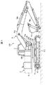
以下、本発明の一実施例を、図面を用いて説明する。図1は、本発明に係る建設機械としての油圧ショベル20の側面図である。油圧ショベル20は、履帯10が巻装された下部走行体1と、この下部走行体の上部に搭載され、前部側に作業者が搭載するキャブ3が後部側にカウンターウエイト8が配置された上部旋回体2と、上部旋回体2の前端部に取り付けられたフロント4とを有している。
Hereinafter, an embodiment of the present invention will be described with reference to the drawings. FIG. 1 is a side view of a
フロント4は、一端部が上部旋回体2に取り付けられ、俯仰動可能なブーム4aと、ブーム4aの他端部に一端側が取り付けられ俯仰動可能なアーム4bと、アーム4bの先端側に取り付けたアタッチメント4cとを有している。なお、本実施例ではアタッチメント4cとしてバケットを示しているが、アタッチメント4cはバケットに限るものではない。
One end of the front 4 is attached to the
これらブーム4a及びアーム4b、バケット4cを駆動するために、ブームシリンダ5a及びアームシリンダ5b、バケットシリンダ5cが設けられており、ブームシリンダ5aの両端部は上部旋回体2とブーム4aに、アームシリンダ5bの両端部はブーム4aとアーム5bに、バケットシリンダ5cの両端部はアーム5bとバケット5cにそれぞれ取り付けられている。
In order to drive the
上部旋回体2の左前方にはキャブ3が配置されており、間にフロント4を挟んで右前方には工具箱25が配置されている。工具箱25の後方には、カバー34や建屋カバー36が配置されており、これら工具箱25やカバー34、建屋カバー36は、旋回フレーム26上に設けられている。そして油圧ショベル20のメンテナンス時等には、工具箱25やカバー34、建屋カバー36の上面に、作業員が立ち入ることが可能になっている。また、工具箱25の内部には、詳細を後述する尿素水のタンク60が収納されている。
A
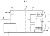
図2に、油圧ショベル20の上部旋回体2部分を上面図で示す。上述したように、旋回フレーム26の右側前部には工具箱25が配置されており、旋回フレーム26の後部には、エンジンルーム17が配置されている。エンジンルーム17内には、ディーゼルエンジン18が配置されており、図示しない油圧ポンプやこの油圧ショベル20を駆動する駆動源となっている。
FIG. 2 is a top view of the
エンジン18の軸端には、オイルクーラやラジエータ等で構成されるクーラー14に送風するための冷却ファン15が取り付けられている。一方、エンジン18の排気管19の先端部には、尿素水を排ガスに噴射して窒素酸化物NOxを低減するための排ガス処理装置16が配置されており、ディーゼルエンジン18の排気を浄化している。
A
ここで、ディーゼルエンジンを使用すると、エンジンの排気ガス中には窒素酸化物NOxが多く含まれる。近年、ディーゼルエンジン車の排ガス規制が強化され、NOxの低減が求められている。NOx低減方法の一つとして、SCR(selective catalytic reduction;選択還元型触媒法)が唱導されている。この方法は、取り扱いが容易でないアンモニアに代わり、無害で安全な尿素水をエンジン排気中に噴射して触媒の化学反応でNOxを削減する方法である。排ガス中に噴射する尿素水については、JIS K2247−1またはISO 2241−1により規定されている。 Here, when a diesel engine is used, the exhaust gas of the engine contains a large amount of nitrogen oxides NOx. In recent years, exhaust gas regulations for diesel engine vehicles have been strengthened, and NOx reduction has been demanded. As one of NOx reduction methods, SCR (selective catalytic reduction) has been introduced. This method is a method of injecting harmless and safe urea water into the engine exhaust instead of ammonia that is not easy to handle and reducing NOx by a chemical reaction of the catalyst. The urea water injected into the exhaust gas is defined by JIS K2247-1 or ISO 2241-1.
上述したように、ディーゼルエンジン18の排ガス対策に尿素水を用いると排ガスは浄化されるが、特許文献1に記載のように尿素水は低温(−11℃以下)では凍結する恐れがあり、エンジンに近い場所に保持する必要がある。そのため通常、フロント4の端部を挟んでキャブ3とは反対側の前側の工具箱25内に設けた尿素水タンク60内に貯蔵されている。
As described above, when urea water is used as an exhaust gas countermeasure for the
なお浄化に必要な尿素水量は、燃料のほぼ3%程度であるので、尿素水タンク60の容量は燃料タンクの容量に応じて約20〜80L程度に設定されている。このように多量の尿素水を油圧ショベル20に搭載するために、例えば三井物産のカタログ(http://mitsui-adblue.jp/product/lineup_backin.html)に記載のバック・イン・ボックス(BIB)の20L容器から、付設のノズルを用いて尿素水タンク60に供給する。
Since the amount of urea water required for purification is about 3% of the fuel, the capacity of the
以下、BIBから尿素水タンク60への尿素水の供給の詳細を、図3ないし図7を用いて説明する。図3は、工具箱25周りの斜視図である。工具箱25は、ブーム取付孔2b及びブームシリンダ取付孔2aが形成されたセンターフレーム2cに隣り合って配置されている。
Details of the supply of urea water from the BIB to the
油圧ショベル20の右側面部の旋回フレーム26上には、燃料タンクやオイルタンクが配置されており、これらのタンクの上面は建屋カバー36で覆われている。建屋カバー36の前方の旋回フレーム26上面は階段状に形成されており、階段内部は尿素水タンク60が格納可能になっている。図3では2段の階段となっている。
A fuel tank and an oil tank are disposed on the revolving
上段側の階段は、カバー34と、カバー34の上面側を開放できるようにカバー34の前面と上面の一部にわたって設けられた開閉扉35とを有している。下段側の階段は、前面部32a及び上面部32bの一部を切り取った形状のカバー32と、この切り取部を開閉する折れ曲がり形状の開閉扉33とを有している。開閉扉33の前面部であって端部近傍には、開閉のため取っ手部33bが形成されている。開閉扉33の後端部には、ヒンジ33aが取り付けられており、開閉扉33を開閉可能にしている。旋回フレーム26の前端には多数の泥落とし用の孔31aが形成されたステップ31が取り付けられている。ステップ31と上記カバー32、34は、油圧ショベルの建屋カバー36に作業員が立ち入る際の階段として設けられている。
The upper stairs include a
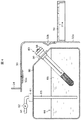
図4に、工具箱25部の前後方向での断面図を示す。開閉扉33は閉じた状態である。工具箱25の内部には、尿素水タンク60が収容されている。尿素水タンク60は、角部が丸く形成された直方体状の箱の前面側上部を切り落とした断面5角形状であり、切り落とし部の斜面に詳細を後述するストレーナ40が取り付けられており、ストレーナ40の先端部にはキャップ58が取り付けられている。尿素水タンク60を断面5角形状にするのは、万一尿素水タンク60に収容された尿素水65が凍結して体積が増大しても、尿素水タンク60の破損等を生じないように上部に隙間を形成するためである。
FIG. 4 shows a cross-sectional view of the
つまり、尿素水タンク60の斜面部から尿素水を供給することにより、尿素水65の液面66は、尿素水タンク60内部の天井面との間に隙間がある位置で留まる。従って尿素水タンク60の内部で尿素水65が膨張しても、隙間が狭くなるだけである。なお凍結を防止する目的では尿素水タンク60を合成樹脂製とするのが良く、凍結が生じても尿素水タンク60に過大な応力が加わらないようにするためには、尿素水タンク60をステンレス製とするのがよい。
That is, by supplying urea water from the slope portion of the
尿素水タンク60の上面には、尿素水65を排ガス処理装置16へ導く配管64を取り付けるための取付け具61が設けられている。また、取付け具61に接続して、尿素水タンク60内へ延びる吸込み管63が設けられている。排ガス処理装置16へ導く配管64の途中には、ポンプ62が設けられており、尿素水タンク60内の尿素水65を吸込んで排ガス処理装置16に導くことを可能にしている。
On the upper surface of the
省スペースのために、尿素水タンク60を収容する階段状のカバー32及びこのカバー32の開口部を覆う開閉扉33は、尿素水タンク60に近接して設けられている。そのため、尿素水タンク60に上述した市販のBIBのノズルから尿素水65を供給しようとしても、開閉扉33やカバー32の前面部32aが邪魔になり、尿素水タンク60の斜面部に形成した供給孔に取り付けたストレーナ40から尿素水65を供給する際、尿素水65がこぼれおちて油圧ショベル20を汚す恐れがある。その場合、鉄、銅、砲金、アルミ等の部品では腐食が発生する恐れがあるので、拭き取りが必要となる。
In order to save space, a step-
そこで本発明に係るストレーナ40は尿素水タンク60に進退自在であり、尿素水65の供給時には、先端部が工具箱25部から外に出るようにして、尿素水のBIBのノズルとの接続を容易にするとともに、接続部からの漏れを防止している。また、尿素水の供給時以外には、ストレーナ40の大部分が尿素水タンク60内に退避して、先端部が尿素水タンク60の切り落とし部から余りはみ出ない状態で保持される。これにより、カバー32と尿素水タンク60とを近接でき、省スペースを実現できる。
Therefore, the
本発明に係るストレーナ40の詳細を、図5に示す。図5(a)は、ストレーナ40の斜視図であり、尿素水65を尿素水タンク60に供給する際の状態を示す図である。図5(b)は、ストレーナ40の斜視図であり、ストレーナ40の不使用時の状態を示す図である。これらの図ではストレーナ40の先端に取り付けるキャップ58を省略している。図5(c)は、ストレーナ40の先端部を構成するフィラーネック50の斜視図であり、図5(d)はストレーナ40を構成する筒部41の先端部の縦断面形状、図5(e)はフィラーネック50の縦断面形状である。
Details of the
ストレーナ40は、円筒形状の進退部材45と、この進退部材45に係合するフィラーネック50と、この図5では図示しないキャップ58とを主要部品として構成されている。円筒形状の進退部材45の一端側は、フィルター43を収納し、粗い骨組状であって骨組の端部がドーム状に形成された吐出部42を構成している。吐出部42には長尺の円筒状に形成された筒部41が接続している。
The
筒部41の先端部には、フィラーネック50を係止保持するために、周方向の複数個所(図5(a)ではほぼ対称位置に2か所)に、突起46が設けられている。突起46は、図5(d)にその断面を示すように、進退部材45の進退方向の両端側で進退方向に傾斜した上側傾斜部46bおよび下側傾斜部46cを形成している。両傾斜部46b、46c間は突出部46aであり、後述するフィラーネック50に設けた係止穴54aに嵌合する。フィラーネック50との嵌合を容易にするため、複数の突起46のそれぞれの円周方向両側であって筒部41の先端側には、突起長よりも長いスリット47が形成されている。筒部41にスリット47を形成したので、作業者が突起46を筒部41の内側に押し込むことにより、進退部材45とフィラーネック50との嵌合を解除することが可能になる。逆に、フィラーネック50に進退部材45を嵌合させることも可能になる。
筒部41には、筒部41の先端部近傍からこの筒部41の軸方向(進退方向)に延びるガイド溝44が形成されている。ガイド溝44は、軸方向に直線状に延びる進退案内溝44aと、この進退案内溝44aの吐出部42側端部に設けられ、進退案内溝44aにほぼ直角方向に延びる固定用溝44bとから構成されている。
The
フィラーネック50は、軸方向の中間部に設けたフランジ部51とこのフランジ部51の両側に位置するキャップ受け部52およびロック部53とから構成されている。フランジ部51では、尿素水タンク60に固定するためのねじ止め用孔55が、周方向に複数個所形成されている。キャップ受け部52は円筒状であって、フランジ部51の上側(反尿素水タンク60側)に形成されており、外周部にキャップ58が係合するねじまたはロック機構が形成されている。ロック部53も円筒状であり、周方向複数個所に係止穴54aが形成されている。この係止穴54aの周方向位置は、進退部材45に形成した突起46の位置に対応している。
The
円筒形のロック部53の内周側端部には、案内用突起54bが設けられている。案内用突起54bの周方向幅及び突起高さは、進退部材45に形成したガイド溝44の幅及び深さに対応している。したがって、進退部材45は、ガイド溝44において案内用突起54bに係止しながら軸方向に移動可能である。またガイド溝44の吐出部42側端部まで進退部材45を移動させたときには、案内用突起54bに係止しながら固定用溝44bに沿って進退部材45を周方向に回動させて、進退部材45のそれ以上の移動を制限して固定(ロック)できる。
A
つまり、図5(a)に示すように、進退部材45を反尿素水タンク60側に位置させるときには、進退部材45をガイド溝44に沿って軸方向に移動させ、最後に周方向に回動させてロックする。また、ストレーナ40を不使用時には図5(b)に示すように、進退部材45をガイド溝44の固定用溝44bに沿って回動させてロックを解除し、その後進退部材45を軸方向に移動させる。進退部材45が先端まで移動すると、フィラーネック50の係止穴54aに進退部材45の先端部に形成した突起46が係止し、進退部材45の尿素水タンク60内への没入を防止する。
That is, as shown in FIG. 5A, when the advance /
上述のストレーナ40を用いて尿素水タンク60へバック・イン・ボックス(BIB)70から尿素水65を供給する様子を図6に示す。BIB70は不純物の混入を避けるため、専用のノズル71が付設されている。このBIB70を、油圧ショベル20のステップ31に載置することにより、作業者への荷重の負担を軽減する。BIB70内の尿素水容量が減少したら、BIB70を持ち上げて尿素水タンク60に供給する。また、進退部材45の筒部41は、工具室25のカバー32よりも外側まで延びているので、尿素水供給作業が開閉扉33等で邪魔されることなく、作業効率が向上する。万が一尿素水65がこぼれても油圧ショベル20の外面側の拭き取りになり、作業が容易である。なお、BIB70の容量は、20L(市販のポリタンクと同程度)の大きさである。
FIG. 6 shows how the
以上説明したように本実施例のストレーナを用いることにより、BIBから工具室内に収容した尿素水タンクへの尿素水の供給時に、尿素水が外部へこぼれおちるのを防止できる。また、不使用時には進退部材を尿素水タンク側に退避するので、尿素水タンクを収容する工具室の容積を小さくできる、もしくは他の部品を収容する容積を拡大できる。 As described above, by using the strainer of the present embodiment, it is possible to prevent urea water from spilling outside when supplying urea water from the BIB to the urea water tank accommodated in the tool chamber. Further, since the advancing / retreating member is retracted to the urea water tank side when not in use, the volume of the tool chamber accommodating the urea water tank can be reduced, or the volume accommodating other components can be increased.
1…下部走行体、2…上部旋回体、2a…ブームシリンダ取付孔、2b…ブーム取付孔、2c…センターフレーム、3…キャブ、4…フロント、4a…ブーム、4b…アーム、4c…アタッチメント(バケット)、5a…ブームシリンダ、5b…アームシリンダ、5c…バケットシリンダ、8…カウンターウエイト、10…履体、11…駆動輪、12…従動輪、14…クーラー、15…冷却ファン、16…排ガス処理装置、17…エンジンルーム、18…(ディーゼル)エンジン、19…排気管、20…建設機械(油圧ショベル)、25…工具箱、26…旋回フレーム、31…ステップ、31a…泥落とし孔、32…カバー、32a…前面部、32b…上面部、33…開閉扉、33a…ヒンジ、33b…取っ手部、33c…前面部、33d…上面部、34…カバー、35…開閉扉、36…建屋カバー、40…ストレーナ、41…筒部、42…吐出部、43…フィルター、44…ガイド溝、44a…進退案内溝、44b…固定用溝、45…進退部材、46…突起、46a…突出部、46b…(上側)傾斜部、46c…(下側)傾斜部、47…スリット、50…フィラーネック、51…フランジ部、52…キャップ受け部、53…ロック部、54a…係止孔、54b…案内用突起、55…ねじ止め用穴、58…キャップ、60…(尿素水)タンク、61…取付け具、62…ポンプ、63…吸込み管、64…配管、65…尿素水、66…液面、70…バック・イン・ボックス、71…ノズル。
DESCRIPTION OF
Claims (4)
前記タンクはストレーナを有しており、かつ、前記ディーゼルエンジンの燃料タンクの前方に位置する工具室に収容されており、前記ストレーナは不使用時には前記タンクに退避して前記工具室内に保持され、尿素水を前記タンクに供給するときは先端部が前記工具室外まで進展可能となる進退機構を有することを特徴とするストレーナを有するタンク。 A urea water tank for supplying urea water to the exhaust gas purification device, provided in a construction machine equipped with an exhaust gas purification device for purifying exhaust gas of a diesel engine,
The tank has a strainer and is housed in a tool chamber located in front of a fuel tank of the diesel engine, and the strainer is retracted to the tank and held in the tool chamber when not in use. A tank having a strainer, characterized by having an advancing / retreating mechanism that allows the tip portion to advance to the outside of the tool chamber when supplying urea water to the tank.
前記排ガス浄化装置に尿素水を供給するためにサイドフレーム上に配置されたタンクと、このタンクに取り付けられ進退機構を有するストレーナとを有し、前記タンクは、前記ディーゼルエンジンの燃料タンクの前方に位置する工具室に収容されており、前記ストレーナは不使用時には前記タンクに退避して前記工具室内に保持され、尿素水を前記タンクに供給するときは先端部が前記工具室外まで進展可能であり、前記工具室の前面側であって前記サイドフレームにこの建設機械の上面に搭乗するためのステップを設け、前記タンクに尿素水を供給するときに尿素水が充満されたバック・イン・ボックスを前記ステップに載置可能としたことを特徴とするストレーナを有するタンクを備えた建設機械。 In a construction machine equipped with a diesel engine and an exhaust gas purification device for purifying exhaust gas of the diesel engine,
A tank disposed on a side frame for supplying urea water to the exhaust gas purification device; and a strainer attached to the tank and having an advance / retreat mechanism. The strainer is accommodated in the tool chamber located, and when not in use, the strainer is retracted to the tank and held in the tool chamber. A step for boarding the upper surface of the construction machine on the side frame on the front side of the tool room, and a back-in box filled with urea water when supplying urea water to the tank. A construction machine comprising a tank having a strainer that can be placed on the step.
Priority Applications (1)
| Application Number | Priority Date | Filing Date | Title |
|---|---|---|---|
| JP2013263792A JP5965892B2 (en) | 2013-12-20 | 2013-12-20 | Tank having strainer and construction machine having the tank |
Applications Claiming Priority (1)
| Application Number | Priority Date | Filing Date | Title |
|---|---|---|---|
| JP2013263792A JP5965892B2 (en) | 2013-12-20 | 2013-12-20 | Tank having strainer and construction machine having the tank |
Publications (2)
| Publication Number | Publication Date |
|---|---|
| JP2015121102A true JP2015121102A (en) | 2015-07-02 |
| JP5965892B2 JP5965892B2 (en) | 2016-08-10 |
Family
ID=53532942
Family Applications (1)
| Application Number | Title | Priority Date | Filing Date |
|---|---|---|---|
| JP2013263792A Expired - Fee Related JP5965892B2 (en) | 2013-12-20 | 2013-12-20 | Tank having strainer and construction machine having the tank |
Country Status (1)
| Country | Link |
|---|---|
| JP (1) | JP5965892B2 (en) |
Cited By (8)
| Publication number | Priority date | Publication date | Assignee | Title |
|---|---|---|---|---|
| WO2016159048A1 (en) * | 2015-04-03 | 2016-10-06 | ヤマシンフィルタ株式会社 | Strainer |
| JP2018031160A (en) * | 2016-08-24 | 2018-03-01 | 住友建機株式会社 | Shovel |
| WO2018179342A1 (en) * | 2017-03-31 | 2018-10-04 | 日立建機株式会社 | Urea water tank for construction machinery |
| JP2019167681A (en) * | 2018-03-22 | 2019-10-03 | 住友建機株式会社 | Shovel |
| KR102042360B1 (en) * | 2018-10-24 | 2019-11-07 | 김연수 | A injecting cap device of a urea tank |
| JP2019218058A (en) * | 2019-09-05 | 2019-12-26 | ヤンマー株式会社 | Combine |
| JP2020151647A (en) * | 2019-03-19 | 2020-09-24 | 中尾フイルター工業株式会社 | Garbage filtration filter |
| JP2021010386A (en) * | 2020-11-04 | 2021-02-04 | ヤンマーパワーテクノロジー株式会社 | combine |
Citations (4)
| Publication number | Priority date | Publication date | Assignee | Title |
|---|---|---|---|---|
| JPH0735151U (en) * | 1993-12-10 | 1995-06-27 | 日野自動車工業株式会社 | Filler pipe structure of vehicle fuel tank |
| JP2008240676A (en) * | 2007-03-28 | 2008-10-09 | Komatsu Ltd | Construction vehicle |
| JP2011195060A (en) * | 2010-03-20 | 2011-10-06 | Sumitomo (Shi) Construction Machinery Co Ltd | Fuel tank of construction machine |
| JP2013233981A (en) * | 2012-05-09 | 2013-11-21 | Mitsubishi Fuso Truck & Bus Corp | Cap structure of urea water tank |
-
2013
- 2013-12-20 JP JP2013263792A patent/JP5965892B2/en not_active Expired - Fee Related
Patent Citations (4)
| Publication number | Priority date | Publication date | Assignee | Title |
|---|---|---|---|---|
| JPH0735151U (en) * | 1993-12-10 | 1995-06-27 | 日野自動車工業株式会社 | Filler pipe structure of vehicle fuel tank |
| JP2008240676A (en) * | 2007-03-28 | 2008-10-09 | Komatsu Ltd | Construction vehicle |
| JP2011195060A (en) * | 2010-03-20 | 2011-10-06 | Sumitomo (Shi) Construction Machinery Co Ltd | Fuel tank of construction machine |
| JP2013233981A (en) * | 2012-05-09 | 2013-11-21 | Mitsubishi Fuso Truck & Bus Corp | Cap structure of urea water tank |
Cited By (17)
| Publication number | Priority date | Publication date | Assignee | Title |
|---|---|---|---|---|
| US10441902B2 (en) | 2015-04-03 | 2019-10-15 | Yamashin-Filter Corp. | Strainer |
| JP2016196846A (en) * | 2015-04-03 | 2016-11-24 | ヤマシンフィルタ株式会社 | strainer |
| TWI707715B (en) * | 2015-04-03 | 2020-10-21 | 日商雅瑪信過濾器股份有限公司 | filter |
| WO2016159048A1 (en) * | 2015-04-03 | 2016-10-06 | ヤマシンフィルタ株式会社 | Strainer |
| JP2018031160A (en) * | 2016-08-24 | 2018-03-01 | 住友建機株式会社 | Shovel |
| WO2018179342A1 (en) * | 2017-03-31 | 2018-10-04 | 日立建機株式会社 | Urea water tank for construction machinery |
| JPWO2018179342A1 (en) * | 2017-03-31 | 2019-04-04 | 日立建機株式会社 | Urea water tank for construction machinery |
| EP3447196A4 (en) * | 2017-03-31 | 2020-01-15 | Hitachi Construction Machinery Co., Ltd. | Urea water tank for construction machinery |
| US11331605B2 (en) | 2017-03-31 | 2022-05-17 | Hitachi Construction Machinery Co., Ltd. | Urea water tank for construction machine |
| JP2019167681A (en) * | 2018-03-22 | 2019-10-03 | 住友建機株式会社 | Shovel |
| JP7468985B2 (en) | 2018-03-22 | 2024-04-16 | 住友建機株式会社 | Excavator |
| KR102042360B1 (en) * | 2018-10-24 | 2019-11-07 | 김연수 | A injecting cap device of a urea tank |
| JP2020151647A (en) * | 2019-03-19 | 2020-09-24 | 中尾フイルター工業株式会社 | Garbage filtration filter |
| JP7216959B2 (en) | 2019-03-19 | 2023-02-02 | 中尾フイルター工業株式会社 | dust filter |
| JP2019218058A (en) * | 2019-09-05 | 2019-12-26 | ヤンマー株式会社 | Combine |
| JP7084973B2 (en) | 2020-11-04 | 2022-06-15 | ヤンマーパワーテクノロジー株式会社 | combine |
| JP2021010386A (en) * | 2020-11-04 | 2021-02-04 | ヤンマーパワーテクノロジー株式会社 | combine |
Also Published As
| Publication number | Publication date |
|---|---|
| JP5965892B2 (en) | 2016-08-10 |
Similar Documents
| Publication | Publication Date | Title |
|---|---|---|
| JP5965892B2 (en) | Tank having strainer and construction machine having the tank | |
| US20130071295A1 (en) | Work machine | |
| US9708951B2 (en) | Reducing agent tank module | |
| EP2752327B1 (en) | Construction vehicle equipped with exhaust-gas post-processing device | |
| EP2806125B1 (en) | Wheel loader | |
| JP5054841B2 (en) | Wheeled work vehicle | |
| US10323557B2 (en) | Construction machine | |
| EP2949496B1 (en) | Work vehicle | |
| US8985262B2 (en) | Construction vehicle equipped with exhaust aftertreatment device | |
| US9631342B2 (en) | Work vehicle | |
| KR102082850B1 (en) | Urea tank for construction machinery | |
| EP3305993B1 (en) | Construction machine | |
| US10487476B2 (en) | Construction machine | |
| KR102144208B1 (en) | tractor | |
| KR20220000417A (en) | Tractor | |
| JP2017166142A (en) | Construction equipment | |
| KR20140080858A (en) | Installation structure of urea tank for construction machine | |
| JP5963270B2 (en) | Construction machinery with urea water tank | |
| KR20150074191A (en) | Working vehicle | |
| JP5992053B2 (en) | Urea water tank | |
| JP7348937B2 (en) | tractor | |
| JP6005192B2 (en) | Bulldozer | |
| KR101578337B1 (en) | Hydraulic shovel | |
| JP2015148186A (en) | Construction machine |
Legal Events
| Date | Code | Title | Description |
|---|---|---|---|
| A621 | Written request for application examination |
Free format text: JAPANESE INTERMEDIATE CODE: A621 Effective date: 20150904 |
|
| A977 | Report on retrieval |
Free format text: JAPANESE INTERMEDIATE CODE: A971007 Effective date: 20160530 |
|
| TRDD | Decision of grant or rejection written | ||
| A01 | Written decision to grant a patent or to grant a registration (utility model) |
Free format text: JAPANESE INTERMEDIATE CODE: A01 Effective date: 20160614 |
|
| A61 | First payment of annual fees (during grant procedure) |
Free format text: JAPANESE INTERMEDIATE CODE: A61 Effective date: 20160704 |
|
| R150 | Certificate of patent or registration of utility model |
Ref document number: 5965892 Country of ref document: JP Free format text: JAPANESE INTERMEDIATE CODE: R150 |
|
| LAPS | Cancellation because of no payment of annual fees |