JP2015114758A - Information code creation method, information code, information code reading device, and information code utilization system - Google Patents
Information code creation method, information code, information code reading device, and information code utilization system Download PDFInfo
- Publication number
- JP2015114758A JP2015114758A JP2013255058A JP2013255058A JP2015114758A JP 2015114758 A JP2015114758 A JP 2015114758A JP 2013255058 A JP2013255058 A JP 2013255058A JP 2013255058 A JP2013255058 A JP 2013255058A JP 2015114758 A JP2015114758 A JP 2015114758A
- Authority
- JP
- Japan
- Prior art keywords
- area
- code
- image
- information
- augmented reality
- Prior art date
- Legal status (The legal status is an assumption and is not a legal conclusion. Google has not performed a legal analysis and makes no representation as to the accuracy of the status listed.)
- Pending
Links
- 238000000034 method Methods 0.000 title claims description 129
- 230000003190 augmentative effect Effects 0.000 claims abstract description 274
- 239000003550 marker Substances 0.000 claims abstract description 171
- 238000003384 imaging method Methods 0.000 claims description 68
- 238000001514 detection method Methods 0.000 claims description 37
- 238000012545 processing Methods 0.000 claims description 30
- 230000005540 biological transmission Effects 0.000 claims description 4
- 238000012805 post-processing Methods 0.000 claims 2
- 238000012937 correction Methods 0.000 description 114
- 238000010586 diagram Methods 0.000 description 38
- 230000006870 function Effects 0.000 description 36
- 238000007726 management method Methods 0.000 description 32
- 238000006243 chemical reaction Methods 0.000 description 27
- 238000013461 design Methods 0.000 description 18
- 239000004973 liquid crystal related substance Substances 0.000 description 16
- 238000004891 communication Methods 0.000 description 14
- 238000005286 illumination Methods 0.000 description 8
- 238000007639 printing Methods 0.000 description 7
- 239000011159 matrix material Substances 0.000 description 6
- 230000003287 optical effect Effects 0.000 description 5
- 230000000007 visual effect Effects 0.000 description 4
- 230000007274 generation of a signal involved in cell-cell signaling Effects 0.000 description 3
- 230000012447 hatching Effects 0.000 description 3
- 230000010365 information processing Effects 0.000 description 3
- 239000000463 material Substances 0.000 description 3
- 230000003321 amplification Effects 0.000 description 2
- 238000004458 analytical method Methods 0.000 description 2
- 230000008602 contraction Effects 0.000 description 2
- 238000013500 data storage Methods 0.000 description 2
- 238000004519 manufacturing process Methods 0.000 description 2
- 230000000873 masking effect Effects 0.000 description 2
- 238000003199 nucleic acid amplification method Methods 0.000 description 2
- 230000002093 peripheral effect Effects 0.000 description 2
- 238000003672 processing method Methods 0.000 description 2
- HBBGRARXTFLTSG-UHFFFAOYSA-N Lithium ion Chemical compound [Li+] HBBGRARXTFLTSG-UHFFFAOYSA-N 0.000 description 1
- 238000004364 calculation method Methods 0.000 description 1
- 239000003086 colorant Substances 0.000 description 1
- 230000006835 compression Effects 0.000 description 1
- 238000007906 compression Methods 0.000 description 1
- 239000000470 constituent Substances 0.000 description 1
- 238000009792 diffusion process Methods 0.000 description 1
- 230000000694 effects Effects 0.000 description 1
- 238000005516 engineering process Methods 0.000 description 1
- 229910001416 lithium ion Inorganic materials 0.000 description 1
- 239000007769 metal material Substances 0.000 description 1
- 239000011347 resin Substances 0.000 description 1
- 229920005989 resin Polymers 0.000 description 1
- 239000004065 semiconductor Substances 0.000 description 1
Images


Landscapes
- Processing Or Creating Images (AREA)
Abstract
Description
本発明は、情報コード生成方法、情報コード、情報コード読取装置、及び情報コード利用システムに関するものである。 The present invention relates to an information code generation method, an information code, an information code reader, and an information code utilization system.
現在では、情報コードの用途が多様化しており、コード領域内に写真や図などを配置するような技術も提案されている。例えば、特許文献1の技術では、2次元コードにおいて単一の値として読み取られる領域を形成するビット列を逆変換した逆変換ビット列を求め、逆変換ビット列を2次元コードのフォーマット情報に基づいて変換して2次元コードを生成することにより、単一の階調値から構成されたデザイン領域を有する特殊2次元コードを生成している。
At present, the use of information codes is diversified, and a technique for arranging photographs and drawings in the code area has also been proposed. For example, in the technique of
上記特許文献1の技術では、例えば、デザイン領域が白のモジュールにより構成されている特殊2次元コードの場合には、白として読み取られる範囲の階調値から構成されたデザインがデザイン領域に形成されるように特殊2次元コードと所与のデザインデータとを合成している。一方、デザイン領域が例えば黒のモジュールにより構成されている特殊2次元コードの場合には、黒として読み取られる範囲の階調値から構成されたデザインがデザイン領域に形成されるように特殊2次元コードと所与のデザインデータとを合成している。
In the technique disclosed in
しかしながら、従来から用いられているデザイン領域を含む情報コードは、セル配列等によって表現されるデータのみが解析及び読み取りの対象であり、デザイン領域の絵柄等は専ら利用者に見せるために使われていた。即ち、情報コード内に付されたデザイン等を読取装置側で解析して利用する思想は存在せず、読み取りの際にデザイン領域を利用して利便性を高めることはできなかった。 However, in the information code including the design area that has been used in the past, only the data expressed by the cell array or the like is subject to analysis and reading, and the design area etc. is used exclusively to show the user. It was. That is, there is no idea of analyzing and using the design or the like attached to the information code on the reading device side, and it has not been possible to improve convenience by using the design area at the time of reading.
本発明は、上述した課題を解決するためになされたものであり、情報コードのコード領域内の画像を拡張現実マーカとして利用可能な情報コードの生成方法、情報コード、情報コード読取装置、及び情報コード利用システムを提供することを目的とする。 The present invention has been made to solve the above-described problem, and an information code generation method, an information code, an information code reader, and information that can use an image in the code area of the information code as an augmented reality marker. The purpose is to provide a code utilization system.
第1の発明は、所定のコード領域の内部に情報を表示する単位となるセルを配列した情報コードを情報コード生成装置によって生成する情報コード生成方法であって、
前記コード領域の内部に、予め定められた形状の特定パターンが配置される特定パターン領域と、複数種類の前記セルによってデータを記録するデータ記録領域とを設け、
更に、前記コード領域内に、拡張現実マーカが表示される領域、又は前記拡張現実マーカに加工されるべき領域を設けることを特徴とする。
1st invention is the information code generation method which produces | generates the information code which arranged the cell used as the unit which displays information inside a predetermined code area | region with an information code production | generation apparatus,
Inside the code area, a specific pattern area in which a specific pattern of a predetermined shape is arranged, and a data recording area for recording data by a plurality of types of cells,
Furthermore, an area in which the augmented reality marker is displayed or an area to be processed into the augmented reality marker is provided in the code area.
第2の発明は、所定のコード領域の内部に情報を表示する単位となるセルを配列した情報コードであって、前記コード領域の内部に、予め定められた形状の特定パターンが配置される特定パターン領域と、複数種類の前記セルによってデータを記録するデータ記録領域とが設けられ、更に、前記コード領域内に、拡張現実マーカが表示される領域、又は前記拡張現実マーカに加工されるべき領域が設けられていることを特徴とする。 2nd invention is the information code which arranged the cell used as the unit which displays information in the inside of a predetermined code field, and a specific pattern of a predetermined shape is arranged inside the code field A pattern area and a data recording area for recording data by a plurality of types of cells are provided, and an area where an augmented reality marker is displayed in the code area or an area to be processed into the augmented reality marker Is provided.
第3の発明は、所定のコード領域の内部に情報を表示する単位となるセルが配列され、前記コード領域の内部に、予め定められた形状の特定パターンが配置される特定パターン領域と、複数種類の前記セルによってデータを記録するデータ記録領域とが設けられた情報コードを読み取り可能な情報コード読取装置であって、
前記情報コードは、前記コード領域内に、拡張現実マーカが表示される領域、又は前記拡張現実マーカに加工されるべき領域が設けられた構成であり、
当該情報コード読取装置の装置外に設定される撮像範囲の実画像を撮像可能な撮像部と、
前記撮像部によって撮像される前記実画像を表示可能な表示部と、
前記撮像部によって撮像される前記実画像に前記情報コードの画像が含まれる場合に、前記情報コードの画像又は前記情報コードの画像を加工した加工画像から前記拡張現実マーカの画像を検出するマーカ検出部と、
前記マーカ検出部によって前記拡張現実マーカの画像が検出された場合に、前記撮像部によって撮像される前記実画像又は所定の背景画像に対して拡張現実画像を重畳して前記表示部に表示する表示制御部と、
を有することを特徴とする。
According to a third aspect of the present invention, there are provided a specific pattern region in which cells serving as units for displaying information are arranged inside a predetermined code region, and a specific pattern having a predetermined shape is arranged inside the code region; An information code reader capable of reading an information code provided with a data recording area for recording data by the type of cells,
The information code has a configuration in which an area where an augmented reality marker is displayed or an area to be processed into the augmented reality marker is provided in the code area,
An imaging unit capable of imaging a real image in an imaging range set outside the information code reader;
A display unit capable of displaying the real image captured by the imaging unit;
Marker detection that detects the image of the augmented reality marker from the image of the information code or a processed image obtained by processing the image of the information code when the image of the information code is included in the actual image captured by the imaging unit And
Display in which an augmented reality image is superimposed on the actual image or a predetermined background image captured by the imaging unit and displayed on the display unit when an image of the augmented reality marker is detected by the marker detection unit A control unit;
It is characterized by having.
第4の発明は、所定のコード領域の内部に情報を表示する単位となるセルを配列した情報コードを生成する情報コード生成装置と、
前記情報コード生成装置によって生成された前記情報コードを読み取る情報コード読取装置と、
を備えた情報コード利用システムであって、
前記情報コード生成装置は、前記コード領域の内部に、予め定められた形状の特定パターンが配置される特定パターン領域と、複数種類の前記セルによってデータを記録するデータ記録領域と、拡張現実マーカが表示される領域、又は前記拡張現実マーカに加工されるべき領域とを設けた構成で前記情報コードを生成し、
前記情報コード読取装置は、
当該情報コード読取装置の装置外に設定される撮像範囲の実画像を撮像可能な撮像部と、
前記撮像部によって撮像される前記実画像を表示可能な表示部と、
前記撮像部によって撮像される前記実画像に前記情報コードの画像が含まれる場合に、前記情報コードの画像又は前記情報コードの画像を加工した加工画像から前記拡張現実マーカの画像を検出するマーカ検出部と、
前記マーカ検出部によって前記拡張現実マーカの画像が検出された場合に、前記撮像部によって撮像される前記実画像又は所定の背景画像に対して拡張現実画像を重畳して前記表示部に表示する表示制御部と、
を有することを特徴とする。
A fourth invention is an information code generation device for generating an information code in which cells serving as units for displaying information within a predetermined code area are arranged;
An information code reader for reading the information code generated by the information code generator;
An information code using system comprising:
The information code generation device includes a specific pattern area in which a specific pattern having a predetermined shape is arranged in the code area, a data recording area in which data is recorded by a plurality of types of cells, and an augmented reality marker. Generate the information code in a configuration in which an area to be displayed or an area to be processed into the augmented reality marker is provided,
The information code reader is
An imaging unit capable of imaging a real image in an imaging range set outside the information code reader;
A display unit capable of displaying the real image captured by the imaging unit;
Marker detection that detects the image of the augmented reality marker from the image of the information code or a processed image obtained by processing the image of the information code when the image of the information code is included in the actual image captured by the imaging unit And
Display in which an augmented reality image is superimposed on the actual image or a predetermined background image captured by the imaging unit and displayed on the display unit when an image of the augmented reality marker is detected by the marker detection unit A control unit;
It is characterized by having.
請求項1、6の発明によれば、コード領域内を拡張現実マーカとして利用可能な情報コードを実現できる。特に、情報コードのコード画像内で拡張現実マーカを特定できるようになるため、闇雲に拡張現実マーカを探す方法と比べ、拡張現実マーカをより識別しやすくなる。 According to the first and sixth aspects of the invention, an information code that can be used as an augmented reality marker in the code area can be realized. In particular, since the augmented reality marker can be specified in the code image of the information code, it becomes easier to identify the augmented reality marker as compared with the method of searching the dark cloud for the augmented reality marker.
請求項2、7の発明によれば、コード領域の内部においてデータ記録領域及び特定パターン領域以外の位置に、空き領域を確保することができ、且つこの空き領域を拡張現実マーカの表示領域として利用し得る情報コードを生成することができる。空き領域はセルによってデータ記録領域にデータを記録する方法とは異なる方法で情報又は画像の表示が可能な領域であるため、データ記録領域のセル配列の影響を受け難く、拡張現実マーカをより自由に表現しやすくなる。 According to the second and seventh aspects of the present invention, an empty area can be secured at a position other than the data recording area and the specific pattern area within the code area, and this empty area is used as a display area for the augmented reality marker. Possible information codes can be generated. The empty area is an area where information or images can be displayed by a method different from the method of recording data in the data recording area by cell, so it is less affected by the cell arrangement of the data recording area, and the augmented reality marker is more free It becomes easy to express.
請求項3、8の発明によれば、コード領域の内部においてデータ記録領域及び特定パターン領域以外の位置に、空き領域を確保し得る情報コードを生成することができる。空き領域はセルによってデータ記録領域にデータを記録する方法とは異なる方法で情報又は画像の表示が可能な領域であるため、データ記録領域のセル配列の影響を受け難く、情報や画像をより自由に表現しやすくなる。また、空き領域以外の外部領域(特定パターンやデータ記録領域が設けられた領域)を、拡張現実マーカに加工されるべき領域として利用することができ、外部領域を、情報コードの基本機能を実現するための領域として利用しつつ、拡張現実マーカを表すための領域としても利用できるようになり、スペース的な利点が非常に大きくなる。更に、空き領域については、データ記録領域の影響や拡張現実マーカの影響を抑えて自由に表現しやすくなるため、情報コードを利用する上での利便性が一層高まる。 According to the third and eighth aspects of the present invention, it is possible to generate an information code that can secure an empty area at a position other than the data recording area and the specific pattern area within the code area. An empty area is an area in which information or an image can be displayed by a method different from the method of recording data in the data recording area by a cell. It becomes easy to express. In addition, external areas other than empty areas (areas with specific patterns and data recording areas) can be used as areas that should be processed into augmented reality markers, and the external areas realize the basic functions of information codes. It can be used as an area for representing an augmented reality marker while being used as an area for doing so, and the space advantage becomes very large. Furthermore, since the free area can be expressed freely by suppressing the influence of the data recording area and the influence of the augmented reality marker, the convenience in using the information code is further enhanced.
請求項4、9の発明によれば、1つの情報コードのコード領域から、拡張現実マーカと、拡張現実画像の画像データにアクセスするための情報とを抽出可能となり、読取装置の外部に拡張現実画像の画像データが蓄積されるようなシステムであっても、複雑な操作を伴うことなく読取装置に拡張現実画像の画像データを取得させやすくなる。 According to the fourth and ninth aspects of the present invention, it is possible to extract the augmented reality marker and the information for accessing the image data of the augmented reality image from the code area of one information code. Even in a system in which image data of an image is accumulated, it becomes easier for the reading device to acquire image data of an augmented reality image without complicated operations.
請求項5、10の発明によれば、情報コードのコード領域から、拡張現実マーカと、表示対象の拡張現実画像を特定するための情報とを抽出可能となり、予定された拡張現実画像を表示する上で複雑な操作が抑えられる。更に、コード領域には、予定された拡張現実画像に関連した表示(表示対象の拡張現実画像に対応した画像又は情報の表示)がなされるため、読み取り前に関連表示を視認して拡張現実画像を把握或いは推測することが可能となり、利便性が一層高まる。 According to the fifth and tenth aspects of the present invention, the augmented reality marker and information for specifying the augmented reality image to be displayed can be extracted from the code area of the information code, and the scheduled augmented reality image is displayed. Complex operations can be suppressed. Furthermore, since the display related to the scheduled augmented reality image (display of the image or information corresponding to the augmented reality image to be displayed) is made in the code area, the related display is visually recognized before reading the augmented reality image. Can be grasped or estimated, and convenience is further enhanced.
請求項11、17の発明によれば、コード領域内を拡張現実マーカとして利用可能な情報コードを読取対象として、表示部に拡張現実画像を重畳表示し得る構成を実現できる。特に、コード画像に基づいて拡張現実マーカを特定できるようになるため、闇雲に拡張現実マーカを探す方法と比べ、拡張現実マーカをより識別しやすくなる。 According to the eleventh and seventeenth aspects of the present invention, it is possible to realize a configuration in which an augmented reality image can be superimposed and displayed on the display unit with an information code that can be used as an augmented reality marker in the code area being read. In particular, since the augmented reality marker can be specified based on the code image, it is easier to identify the augmented reality marker than the method of searching for the augmented reality marker in the dark clouds.
請求項12、18の発明によれば、空き領域が拡張現実マーカの表示領域とされた情報コードを読取対象として、表示部に拡張現実画像を重畳表示し得る構成を実現できる。更に本発明では、領域検出部によってコード領域の画像を検出し、空き領域特定部によって空き領域の位置を特定した上で拡張現実マーカを探し出すことができるため、拡張現実マーカが確実に存在する狭い領域に絞って効率的に検出を行うことができる。
According to the inventions of
請求項13、19の発明では、空き領域以外の外部領域(特定パターンやデータ記録領域が設けられた領域)を、拡張現実マーカに加工されるべき領域として利用することができ、外部領域を、情報コードの基本機能を実現するための領域として利用しつつ、拡張現実マーカを表すための領域としても利用できるようになり、スペース的な利点が非常に大きくなる。更に、空き領域については、データ記録領域の影響や拡張現実マーカの影響を抑えて自由に表現しやすくなるため、情報コードを利用する上での利便性が一層高まる。
In the inventions of
請求項14、20の発明では、1つの情報コードのコード領域から、拡張現実マーカと、拡張現実画像の画像データにアクセスするための情報とを抽出可能となり、読取装置の外部に拡張現実画像の画像データが蓄積されるようなシステムであっても、複雑な操作を伴うことなく読取装置に拡張現実画像の画像データを取得させやすくなる。
In the inventions of
請求項15、21の発明では、情報コードのコード領域から、拡張現実マーカと、表示対象の拡張現実画像を特定するための情報とを抽出可能となり、予定された拡張現実画像を表示する上で複雑な操作が抑えられる。また、同一のコード領域内の要素に基づく同時期の読み取りによって拡張現実マーカの認識と拡張現実画像の特定がなされるため、拡張現実マーカの認識と拡張現実画像の特定を別々に行うような構成と比べて、拡張現実マーカに対応付けて予定された画像(表示対象の拡張現実画像)をより迅速に且つより正確に表示できるようになる。 According to the fifteenth and twenty-first aspects of the present invention, it is possible to extract the augmented reality marker and information for specifying the augmented reality image to be displayed from the code area of the information code, and display the planned augmented reality image. Complex operations can be suppressed. In addition, since augmented reality markers are recognized and augmented reality images are identified by simultaneous reading based on elements in the same code area, augmented reality markers are recognized separately from augmented reality images. As compared with the above, an image (augmented reality image to be displayed) scheduled to be associated with the augmented reality marker can be displayed more quickly and more accurately.
請求項16、22の発明では、コード領域内において予めなされている表示(表示対象の拡張現実画像に対応した画像又は情報の表示)に関連する拡張現実画像を重畳表示することができるため、利用者が読み取り前に拡張現実画像を把握或いは推測しやすい構成となり、利便性が一層高まる。
In the inventions of
[第1実施形態]
以下、本発明を具現化した第1実施形態について、図面を参照して説明する。
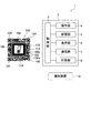
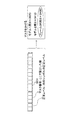
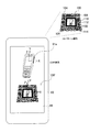
図1に示す情報コード利用システム1は、所定のコード領域の内部に情報を表示する単位となるセルを配列した情報コード100を生成する情報コード生成装置2と、情報コード生成装置2によって生成された情報コード100を読み取る情報コード読取装置10とを備えている。また、このシステム1は、図11のように、読取装置10と管理装置90とが、インターネット通信網や無線LAN通信網などを介して通信可能に接続されている。なお、管理装置90と生成装置2と通信可能に接続されていてもよく、生成装置2によって管理装置90が構成されていてもよい。
[First embodiment]
Hereinafter, a first embodiment embodying the present invention will be described with reference to the drawings.
An information
(情報コード生成装置)
情報コード生成装置2は、例えばパーソナルコンピュータ等の情報処理装置として構成されており、CPUなどからなる制御部3と、キーボード、マウス、その他の入力装置からなる操作部4と、ROM、RAM、HDD、不揮発性メモリ等の記憶装置からなる記憶部5と、公知の表示装置(液晶ディスプレイやその他の表示デバイス)などからなる表示部6と、外部装置と有線通信或いは無線通信を行うための通信インタフェースとして機能する通信部7と、公知のプリンタ等と同様のハードウェア構成をなし且つ制御部3からの印刷データに基づいて情報コード100等を印刷可能な印刷部8(印刷装置)とを備えている。
(Information code generator)
The information
(情報コード読取装置)
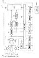
次に、情報コード読取装置10の全体構成について説明する。図2に示すように、情報コード読取装置10は、ハードウェア的には二次元コードを読取可能なコードリーダとして構成されており、図示しないケースによって外郭が構成され、このケース内に各種電子部品が収容された構成をなしている。
(Information code reader)
Next, the overall configuration of the
この情報コード読取装置10は、主に、照明光源21、受光センサ23、フィルタ25、結像レンズ27等の光学系と、メモリ35、制御回路40、操作スイッチ42、液晶表示器46等のマイクロコンピュータ(以下「マイコン」という)系と、電源スイッチ41、電池49等の電源系と、から構成されている。なお、これらは、図略のプリント配線板に実装あるいはケース(図示略)内に内装されている。
The
光学系は、照明光源21、受光センサ23、フィルタ25、結像レンズ27等から構成されている。照明光源21は、照明光Lfを発光可能な照明光源として機能するもので、例えば、赤色のLEDとこのLEDの出射側に設けられる拡散レンズ、集光レンズ等とから構成されている。本構成では、受光センサ23を挟んだ両側に照明光源21が設けられており、ケースに形成された読取口(図示略)を介して読取対象物Rに向けて照明光Lfを照射可能に構成されている。この読取対象物Rとしては、例えば、樹脂材料、金属材料等の様々な対象が考えられ、このような読取対象物Rに例えば図1のような情報コード100(後述)が印刷などの公知の画像形成方法によって形成されている。
The optical system includes an
受光センサ23は、情報コード100(後述)を撮像可能な「撮像部」の一例に相当し、読取対象物Rや情報コード100に照射されて反射した反射光Lrを受光可能に構成されるもので、例えば、C−MOSやCCD等の固体撮像素子である受光素子を2次元に配列したエリアセンサが、これに相当する。この受光センサ23は、結像レンズ27を介して入射する入射光を受光面23aで受光可能に図略のプリント配線板に実装されている。
The
フィルタ25は、例えば反射光Lrの波長相当以下の光の通過を許容し、当該波長相当を超える光の通過を遮断し得る光学的なローパスフィルタで、ケースに形成された読取口(図示略)と結像レンズ27との間に設けられている。これにより、反射光Lrの波長相当を超える不要な光が受光センサ23に入射することを抑制している。また、結像レンズ27は、例えば、鏡筒とこの鏡筒内に収容される複数の集光レンズとによって構成されており、本実施形態では、ケースに形成された読取口(図示略)に入射する反射光Lrを集光し、受光センサ23の受光面23aに情報コード100のコード画像を結像するように構成されている。
The
マイコン系は、増幅回路31、A/D変換回路33、メモリ35、アドレス発生回路36、同期信号発生回路38、制御回路40、操作スイッチ42、LED43、ブザー44、液晶表示器46、通信インタフェース48等から構成されている。このマイコン系は、マイコン(情報処理装置)として機能し得る制御回路40及びメモリ35を中心として構成され、前述した光学系によって撮像された情報コード100の画像信号をハードウェア的およびソフトウェア的に信号処理し得るものである。
The microcomputer system includes an
光学系の受光センサ23から出力される画像信号(アナログ信号)は、増幅回路31に入力されることで所定ゲインで増幅された後、A/D変換回路33に入力され、アナログ信号からディジタル信号に変換される。そして、ディジタル化された画像信号、つまり画像データ(画像情報)は、メモリ35に入力され、当該メモリ35の画像データ蓄積領域に蓄積される。なお、同期信号発生回路38は、受光センサ23およびアドレス発生回路36に対する同期信号を発生可能に構成されており、またアドレス発生回路36は、この同期信号発生回路38から供給される同期信号に基づいて、メモリ35に格納される画像データの格納アドレスを発生可能に構成されている。
An image signal (analog signal) output from the
メモリ35は、半導体メモリ装置などの公知の記憶媒体よって構成され、例えばRAM(DRAM、SRAM等)やROM、不揮発性メモリ等がこれに相当する。このメモリ35のうちのRAMには、前述した画像データ蓄積領域のほかに、制御回路40が算術演算や論理演算等の各処理時に利用する作業領域や読取条件テーブルも確保可能に構成されている。またROMには、後述する読取処理等を実行可能な所定プログラムやその他、照明光源21、受光センサ23等の各ハードウェアを制御可能なシステムプログラム等が予め格納されている。
The
制御回路40は、情報コード読取装置10全体を制御可能なマイコンであり、CPU、システムバス、入出力インタフェース等からなり、情報処理機能を有している。この制御回路40には、内蔵された入出力インタフェースを介して種々の入出力装置(周辺装置)が接続されており、本実施形態の場合、電源スイッチ41、操作スイッチ42、LED43、ブザー44、液晶表示器46、通信インタフェース48等が接続されている。通信インタフェース48は、外部装置(ホストコンピュータHSTや図10に示す管理装置90など)と通信を行うためのインタフェースとして構成されており、例えば、公知の無線通信方式又は有線通信方式によって外部装置と通信を行うように機能している。
The
電源系は、電源スイッチ41、電池49等により構成されており、制御回路40により管理される電源スイッチ41のオンオフによって、上述した各装置や各回路に、電池49から供給される駆動電圧の導通や遮断が制御されている。なお、電池49は、所定の直流電圧を発生可能な2次電池で、例えば、リチウムイオン電池等がこれに相当する。
The power supply system includes a
(情報コード)
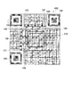
次に、図1の情報コード利用システムで利用される情報コード100について図1、図5等を参照して説明する。なお、図1の例と図5右図の例では、セル配列や特定パターンのサイズ等が若干異なるが基本的な考えは同様であり、同様の特徴を有している。図1、図5等に示す情報コード100は、例えば上述の情報コード生成装置2によって生成されるものであり、所定のコード領域の内部に情報を表示する単位となるセル102(明色セル102a又は暗色セル102b)を配列した構成となっている。なお、図1、図5等の情報コード100において、「コード領域」は、複数配列された暗色セルを全て含み得る矩形状の領域であり、情報コード100を構成する複数種類のセルを全て含む最小の正方形領域又は長方形領域となっている。具体的には、特定パターン領域、データ記録領域、誤り訂正データ記録領域を全て含む最小の正方形領域又は長方形領域となっており、図1等の例では、3つの位置検出パターン(切り出しシンボル)104を全て含む最小の正方形領域又は長方形領域となっている。なお、図1、図5等の例では、特定パターン領域、データ記録領域、誤り訂正データ記録領域を構成する複数のセル102が、矩形状(例えば外径が正方形状)の明色(白色)セル102a又は暗色(黒色)セル102bのいずれかによって構成されており、コード領域の内部において後述する空き領域110の周囲にこれらセル102がマトリックス状に配置されている。明色セル102a及び暗色セル102bは、それぞれ白色セル、黒色セルに限られるものではなく、暗色セル102bが所定の明度で構成される場合、明色セル102aはそれよりも明度が高ければよい。また、情報コード100において上記コード領域の周囲には、当該コード領域を取り囲むように明色又は暗色のマージン領域が構成されるようになっており、図1、図5等の例では、明色(例えば、白色或いは暗色セルよりも明度の大きい他色)のマージン領域がコード領域の周囲に隣接して配置されている。
(Information code)
Next, the
この情報コード100は、矩形状(例えば、正方形状或いは長方形状等)のコード領域の内部に、予め定められた形状の特定パターンが配置される特定パターン領域と、複数種類のセル102によってデータを記録するデータ記録領域と、複数種類のセル102によって誤り訂正符号を記録する誤り訂正符号記録領域とが設けられている。図1、図5等のように、情報コード100の特定パターンは、例えば、QRコード(登録商標)の公知の所定型番(図5の例では、JIS等で規格化されたQRコードの所定型番)の特定パターンと同一の形状及び位置となっており、図1、図5等の例では、コード領域の3つの角部にそれぞれ、特定パターンとしての位置検出パターン(切り出しシンボル)104が配置されている。また、上記所定型番において予め定められた位置に、特定パターンとしてのタイミングパターン106やアライメントパターン108も設けられている。このように、情報コード100では、予め定められた位置に決まった形状の特定パターン(位置検出パターン104(以下、特定パターン104とも称する)、タイミングパターン106、アライメントパターン108(図5では省略))が配置されるようになっている。なお、コード領域の内部において、後述する空き領域110以外の位置は、このような特定パターンの領域、記録領域(データ記録領域及び誤り訂正符号記録領域のいずれかからなる領域)などによって構成されている。
The
情報コード100のセルの行数及び列数、特定パターンの形状及び位置、フォーマット情報の位置、コードワードの候補位置(コードワードの配置順序を特定するアドレス)等は読取装置がどのような方法で把握してもよい。例えば、情報コード100の種別において複数の型番が設けられていてもよく、この場合、型番毎にセルの行数及び列数、特定パターンの形状及び位置、フォーマット情報の位置、コードワードを配置する候補位置(アドレス)が予め定められていればよい。そして、上記型番を特定する型番情報がコード領域内の決められた位置(予約領域)に配置されていれば、読取装置はこの型番情報に基づいて情報コード100のセルの行数及び列数、特定パターンの形状及び位置、フォーマット情報の位置、コードワードの候補位置(アドレス)を把握できるようになる。なお、この方法に限定されるものではなく、読取装置が把握し得る方法であれば他の方法でもよい。
The number of rows and columns of cells of the
そして、コード領域の内部において、特定パターン領域、データ記録領域、誤り訂正符号記録領域以外の位置には、セル102によってデータが記録されない領域であり且つ誤り訂正符号による誤り訂正の対象にならない領域である空き領域110が、単一のセル102のサイズよりも大きいサイズで設けられている。なお、図1、図5等の例では、データ記録領域、誤り訂正符号記録領域がコード領域の周縁に沿って環状且つ矩形状に配置されており、コード領域の中央部(コード領域の中心を含む所定領域)に空き領域110が構成されている。なお、「セル102によってデータが記録されない領域」とは、即ち、後述するデータコードワードや誤り訂正コードワードなどのコードワードが記録されない領域であり、且つフォーマット情報が記録されない領域であることを意味する。また、「誤り訂正符号による誤り訂正の対象にならない領域」とは、即ち、誤り訂正符号記録領域に記録された誤り訂正符号を用いた誤り訂正が行われない領域であることを意味する。従って、空き領域110に何らかの表示がなされていても、空き領域110の周囲に存在する誤り訂正符号記録領域の誤り訂正符号によってその表示に対する誤り訂正がなされることはない。
Within the code area, the area other than the specific pattern area, data recording area, and error correction code recording area is an area where data is not recorded by the
なお、以下の説明では、図5右図のような上記所定型番に対応する構成と、図5左図のような所定型番よりもサイズが小さい別の型番(Ver.番号)とが対応付けられ、図5右図の情報コード100の各コードワードの位置と、図5左図の他種コード120の各コードワードの位置とが図5下図のような配置変換表によって対応付けられている例を代表例として説明する。この例では、図5左図の他種コード120で格納し得るデータ量であれば、図5右図のような情報コード100により空き領域110を設けた上で表現できるようになっている。逆に、図5右図の情報コード100を読み取る場合には、情報コード100の各コードワードを、図5左図のような他種コード120のコードワードとして読み取ることができるようになっている。
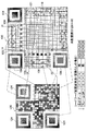
In the following description, a configuration corresponding to the predetermined model number as shown in the right diagram of FIG. 5 is associated with another model number (Ver. Number) having a smaller size than the predetermined model number as illustrated in the left diagram of FIG. An example in which the position of each code word of the
また、図5右図では、空き領域110の周囲に配置される各コードワードの領域を破線枠等によって概念的に示している。なお、図5右図では、一部のコードワードの領域のみを概念的に示し、残りのコードワードの領域の図示を省略しているが、空き領域110の周囲を埋めるように他のコードワードも配置することができる。また、フォーマット情報を記録する領域(所定位置105)は、所定種類のハッチングにて概念的に示している。なお、図5右図では、フォーマット情報を記録する領域や、コードワードを記録する領域では、升目のみを示し、明色セルや暗色セルの具体的配列を省略して示している。また、図5右図の例では、セル配列と対応付けるべく空き領域110(コード領域の中央部分)の内部にも升目を付しているが、空き領域110の構成は自由であり、図1のように構成してもよく、その他の構成であってもよい。
In the right diagram of FIG. 5, each codeword area arranged around the
フォーマット情報(形式情報)は、例えば図6のように構成されて情報コード100内の所定位置105(所定種類のハッチング位置)に特定のフォーマット構成で記録されている。このフォーマット情報は、誤り訂正レベルを特定する訂正レベル情報と、マスク番号を特定するマスク番号情報とを含んでいる。訂正レベル情報は、情報コード100で用いる誤り訂正レベルを特定する情報であり、例えば他種コード120に変換して読み取る場合の当該他種コード120で用いる誤り訂正レベルにも相当する。また、マスク番号は、情報コード100のコードワード領域(データコードワードや誤り訂正コードワードが記録されている領域)にかけられているマスクがどのマスク種別であるかを特定する情報である。
The format information (format information) is configured as shown in FIG. 6, for example, and is recorded at a predetermined position 105 (a predetermined type of hatching position) in the
図6に示すようにフォーマット情報は、所定種類のマスクパターン(特定マスク)を反映した状態で記録されており、公知のQRコードと同様の方法でフォーマット情報のマスク種別を識別することで、図5右図に示すような特定のコード種別(空き領域110を設けた種別)であることを検出できるようになっている。公知規格のQRコードでは、例えばモデル1として構成する場合には、図6のようなフォーマット情報に対してモデル1用のマスクをかけたときに表現されるデータ(セル配列)を所定位置に記録し、モデル2として構成する場合には、図6のようなフォーマット情報に対してモデル2用のマスクをかけたときに表現されるデータ(セル配列)を所定位置に記録するようになっている。一方、図5に示す本実施形態の情報コード100(空き領域110を有する特別種類のコード)では、図6のようなフォーマット情報に対してモデル1、2とは異なる種類の特定マスク(図6ではフレームQR用と例示)をかけたときに表現されるデータ(セル配列)を所定位置105に記録するようになっている。そして、公知規格のモデル1及びモデル2、情報コード100の種別のいずれの場合でも、記録する訂正レベル(訂正レベル情報)及びマスク番号(マスク番号情報)に対応するチェックデジットが付された上でフォーマット情報が構成されており、その上で各種別用のマスクがかけられるようになっている。具体的には、各種別用のマスクパターンを用いて公知の方法でマスク処理が行われ、マスク処理後のビットパターンが所定位置105に記録されるようになっている。従って、情報コード100のようにフォーマット情報に対して特定マスク(図6ではフレームQR用と例示)をかけた上で所定位置105に記録する場合、このように所定位置105に記録された情報を上記特定マスクに基づいてマスク処理を解除して解読すればチェックデジットが合うため、情報コード100の種別であることを特定することができる。逆に、情報コード100の所定位置105のデータを、モデル1やモデル2のマスクに基づいてマスクを外しても、チェックデジットが合わなくなるため、公知規格のモデル1やモデル2でないことを特定することができる。
As shown in FIG. 6, the format information is recorded in a state reflecting a predetermined type of mask pattern (specific mask), and the format information is identified by identifying the mask type of the format information in the same manner as a known QR code. 5 It is possible to detect a specific code type (type provided with a free area 110) as shown in the right figure. For example, when the
この情報コード100では、特定パターン(位置検出パターン104等)を検出し、公知のQRコードと同様の方法でコード領域、コードの向き、各セル位置を特定した後、公知のQRコードと同様の方法でフォーマット情報が記録された所定位置105を解読することで、解読時に成功したマスクの種別により情報コード100の種別(空き領域110を有する特別種類)であることを特定することができる。そして、解読されたフォーマット情報により、情報コード100で用いる誤り訂正レベルを特定でき、且つ情報コード100のコードワード領域(セルによってデータコードワードや誤り訂正コードワードが記録されている領域)にかけられているマスク種別を特定できるようになっている。
In this
更に、空き領域110の内部には、図1のように、セル配列とは異なる画像を表示できるようになっている。なお、図1、図5の例では、空き領域110(画像領域)の境界を符号121で示しており、この境界121よりも内側が空き領域110となっている。なお、空き領域110(画像領域)の具体的な内容や利用方法は後述する。
Further, an image different from the cell array can be displayed in the
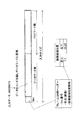
情報コード100に記録する内容は、例えば、図3のような構成をなしており、データ配列の先頭部分にヘッダデータ(フレームQR用ヘッダー)が設定され、ヘッダデータの後に入力データ(解読対象データ)が続くようになっている。図3の例では、入力データ(解読対象データ)については、例えば公知の方法で圧縮し、データワード(データコードワード)に変換しているが、このような圧縮を行わなくてもよい。なお、情報コード100で用いるヘッダデータは、以降の説明では、「フレームQR用ヘッダー」とも称する。また、本明細書では、このようなヘッダデータ及び入力データ(解読対象データ)のデータワード(データコードワード)を記録する領域、及び上述のフォーマット情報を記録する領域が「データ記録領域」に相当する。また、図3の例では、ヘッダデータ(フレームQR用ヘッダー)として、後述する他種コード120(情報コード100を解読するために用いるコード種別であり、配置変換表(図5)によって情報コード100と対応付けられたコード)の種別(型番)を特定し得る情報(図3では、Ver.番号と例示)や、空き領域内の形式を特定し得る識別情報が記録されている。なお、図3の例では、ヘッダデータとして、他種コードの種類(Ver.番号)に加え、空き領域110の形式が図1、図5等に示す画像形式であることを特定する情報(第1情報)と、空き領域110(画像領域)の位置(画像領域位置)を特定し得る情報(第2情報に相当する「画像領域位置情報」)とが記録されている。このうち、空き領域110の形式が画像形式であることを特定する情報(第1情報)は、画像領域の存在を示す「識別情報」の一例に相当する。また、空き領域110(画像領域)の位置(画像領域位置)を特定し得る情報(第2情報)は、コード領域内における画像領域の位置を示す「位置データ」の一例に相当する。
The content recorded in the
図3、図5の例では、画像領域として構成される空き領域110の列位置及び行位置を特定し得る情報が画像領域位置情報(位置データ)として記録されている。より具体的には、図5に示すような矩形状に構成される情報コード100を複数行且つ複数列に格子状に分割したときの空き領域110の左上の行位置及び列位置の組み合わせと、空き領域110の右下の行位置及び列位置の組み合わせとが画像領域位置情報(位置データ)として記録されている。なお、図5のように情報コード100を格子状に分割したときの各行及び各列の幅は、それぞれ単一のセルの行方向の幅及び列方向の幅に相当している。
In the example of FIGS. 3 and 5, information that can specify the column position and row position of the
そして、図3に示すデータ構成では、入力データ(解読対象データであるデータワード)の後には誤り訂正符号となる誤り訂正コードワード(ECCワード)が続いている。情報コード100では、この誤り訂正符号を記録する領域が誤り訂正符号記録領域となる。なお、データワード(図3の例ではヘッダデータ及び入力データ(解読対象データ))に基づいて誤り訂正符号(誤り訂正コードワード)を生成する方法は、公知の二次元コード(QRコード等)の規格で定められた方法などを用いることができる。例えば、データワード(データコードワード)に基づいて誤り訂正コードワードを生成する方法として、JISX0510:2004に規定された誤り訂正コード語の生成方法(JISX0510:2004、8.5誤り訂正)などを用いることができる。なお、誤り訂正コードワードの生成方法はこれに限られず、公知の様々な方法を用いることができる。
In the data configuration shown in FIG. 3, an error correction code word (ECC word) serving as an error correction code follows the input data (data word that is data to be decoded). In the
また、情報コード100では、解読対象データを表現する各データワード(データコードワード)や誤り訂正コードワードが予め定められた配置位置情報に基づいてコード領域内に配置されている。本構成では、図5のように、情報コード100のコード領域内において予め各コードワードの配置候補位置が定められており、各配置候補位置にそれぞれ番号(アドレス)が割り当てられている。そして、配置位置情報は、図3に示す記録内容を構成する各コードワードをそれぞれどの配置候補位置に配置すべきかを特定する情報となっている。なお、図5右図の例では、1〜25番の配置候補位置を概略的に例示しており、各配置候補位置では、先頭と最後のビット部分に番号を付して明示している。また、図5右図では、26番以降の配置候補位置は省略している。
Further, in the
具体的には、他種コード120(公知のQRコード)の型番(図3に示すヘッダデータで特定される他種コード120の型番)では、各順番のコードワードを他種コード120内のどの位置に配置すべきかが公知規格等により予め定められており、他種コード120を解読する場合にはこのように定められた配置に基づいて各順番のコードワードを解読する。例えば、図5左図に示す他種コード120の例では、0番目のコードワードを右下に配置し、1番目のコードワードをその上に配置し、2番目のコードワードをその上に配置するといった具合に各コードワードの配置位置が予め決められている。従って、この他種コード120を解読する場合には、このように決められた配置に基づいて0番目のコードワード、1番目のコードワード、2番目のコードワード、3番目のコードワード・・・といった具合に順番に解読することになる。
Specifically, in the model number of the other type code 120 (known QR code) (the model number of the
一方、図5に示す配置位置情報(配置変換表)では、このように他種コード120で予め定められた各配置位置(各順番のコードワードの配置位置)の番号を、情報コード100において予め定められた候補位置(各コードワードの配置候補位置)の番号にそれぞれ対応付けている。具体的には、「他種コード120における1番目のコードワードの配置位置が情報コード100の1番目の配置候補位置に相当」、「他種コード120における2番目のコードワードの配置位置が情報コード100の2番目の配置候補位置に相当」、「他種コード120における3番目のコードワードの配置位置が情報コード100の3番目の配置候補位置に相当」といった情報が、例えばテーブルデータなどとしてそれぞれ記録されており、他種コード120における各番号のコードワードの配置位置を、情報コード100の各配置候補位置にそれぞれ対応付けている。このように構成されているため、情報コード100を解読する場合には、コード領域内の各配置候補位置のコードワード(各アドレスのコードワード)を配置位置情報(配置変換表)で対応付けられた他種コード120の各配置位置にそれぞれ配置し直し、このように配置し直された他種コード120を公知の方法で解読すれば良い。例えば、図5下図に示す配置変換表を用いて情報コード100の解読を行う場合、情報コード100の1番目の配置候補位置のコードワードを他種コード120における1番目のコードワードの配置位置に配置し、情報コード100の2番目の配置候補位置のコードワードを他種コード120における2番目のコードワードの配置位置に配置し、情報コード100のN番目の配置候補位置のコードワードを他種コード120において当該N番目の配置候補位置に対応付けられているM番目のコードワードの配置位置に配置するといった具合にそれぞれ配置し直した上で、このように配置し直された他種コード(QRコード)を公知の方法で解読すればよい。なお、上述の配置位置情報(配置変換表)については、情報コード100を生成する情報コード生成装置2及び情報コード100を読み取る情報コード読取装置10に共通のデータ(共通の配置変換表)がそれぞれ設けられていることが望ましい。
On the other hand, in the arrangement position information (arrangement conversion table) shown in FIG. 5, the numbers of the arrangement positions (arrangement positions of the code words in each order) determined in advance by the other-
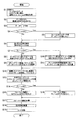
(情報コードの生成処理)
次に、図8等を参照して情報コード生成処理及び情報コード生成方法について説明する。以下では、図5のように他種コード120がQRコード(登録商標)であり、情報コード100がQRコードと同様の特定パターンを有する場合を例に挙げて説明する。なお、この例では、空き領域110を有する情報コード100を「フレームQR」とも称する。
(Information code generation process)
Next, an information code generation process and an information code generation method will be described with reference to FIG. In the following, a case where the
図8の情報コード生成処理は、情報コード生成装置2によって行われる処理であり、例えば、操作部4での所定操作によって実行される。この処理では、まず、外部からコード化するデータ(解読対象データ)と、属性データと、コード種別データ(情報コード100を生成するか、一般的な二次元コード(例えば一般的なQRコード)を生成するかを特定するデータ)を取得する(S1)。なお、本構成では、制御部3、操作部4が「データ取得部」の一例に相当し、解読対象データ(外部からの入力データ)を取得するように機能する。また、このような例に限らず、例えば、制御部3と通信部7が「データ取得部」として構成され、外部から通信によって入力されるデータを解読対象データとして取得するように機能してもよい。
The information code generation process of FIG. 8 is a process performed by the information
S1でデータを取得した後には、その取得したデータを圧縮する方法を公知の方法で定め(S2)、入力データを圧縮したデータ(解読対象データ)を複数のデータワード(データコードワード)で表現する(S3)。そして、S3の後には、S1で取得されたコード種別データが、空き領域110を有する情報コード100の種別(フレームQR)であるか否かを判断する。S1で取得されたコード種別データが、空き領域110を有する情報コード100の種別(フレームQR)である場合には、S4にてYesに進み、空き領域110を有する情報コード100の種別(フレームQR)で用いられる特有のヘッダデータ(上述)を生成し、図3のように複数のデータワードを含んだデータ配列の先頭にセットする(S5)。図3のヘッダデータには、上述したように、図5右図に示す他種コード120の種別(型番)を特定し得る情報(バージョン番号情報等)と、空き領域110の形式が画像形式であることを特定する情報(第1情報)と、空き領域110(画像領域)の位置を特定し得る情報(第2情報に相当する「画像領域位置情報」)とが記録されることになる。一方、S1で取得されたコード種別データが、空き領域110を有する情報コード100の種別(フレームQR)でない場合(一般的な二次元コードを選択するデータ(例えば、モデル1又はモデル2を選択するデータ)である場合)には、S4にてNoに進む。
After acquiring the data in S1, a method for compressing the acquired data is determined by a known method (S2), and the compressed data (decoded data) is expressed by a plurality of data words (data code words). (S3). After S3, it is determined whether or not the code type data acquired in S1 is the type (frame QR) of the
S4でNoに進む場合、S3で生成されたデータワード(データコードワード)の構成に基づいて公知の方法で誤り訂正符号を生成し、この誤り訂正符号を表現する複数の誤り訂正ワード(誤り訂正コードワード)を生成する(S6)。一方、S4からS5に進む場合、S3、S5で生成された最終的なデータワード(ヘッダデータ及び入力データを表現する複数のデータコードワード)の構成に基づいて公知の方法で誤り訂正符号を生成し、この誤り訂正符号を表現する複数の誤り訂正ワード(誤り訂正コードワード)を生成する(S6)。 When the process proceeds to No in S4, an error correction code is generated by a known method based on the configuration of the data word (data code word) generated in S3, and a plurality of error correction words (error correction) representing the error correction code are generated. Codeword) is generated (S6). On the other hand, when proceeding from S4 to S5, an error correction code is generated by a known method based on the configuration of the final data word (a plurality of data code words representing header data and input data) generated in S3 and S5. Then, a plurality of error correction words (error correction code words) representing the error correction code are generated (S6).
S6の後には、S1で取得されたコード種別データが、空き領域110を有する情報コード100の種別(フレームQR)であるか否かを判断する(S7)。そして、S1で取得されたコード種別データが、空き領域110を有する情報コード100の種別(フレームQR)でない場合には、S7にてNoに進み、公知の方法で二次元コード(例えばQRコード)を生成することになる。S7でNoに進む場合、S3で生成されたデータワード(データコードワード)及びS6で生成された誤り訂正ワード(誤り訂正コードワード)を格納しうるサイズの二次元コードの型番(この例では、規格化された公知のQRコードの複数の型番において、S3で生成されたデータワード及びS6で生成された誤り訂正ワードを格納しうるサイズの型番)を決定し、当該型番で予め定められた配置パターンに従い、S3で生成されたデータワード及びS6で生成された誤り訂正ワードを配置する(S9)。
After S6, it is determined whether or not the code type data acquired in S1 is the type (frame QR) of the
一方、S1で取得されたコード種別データが、空き領域110を有する情報コード100の種別(フレームQR)である場合には、S7にてYesに進み、S3、S5で生成されたデータワード(データコードワード)と、S6で生成された誤り訂正ワード(誤り訂正コードワード)と、空き領域と、を格納しうる情報コード100の型番を決定する(S10)。なお、空き領域のサイズは、予め定められた一定サイズであってもよく、S10の前段階でユーザが入力などによって指定してもよい。また、空き領域のサイズは、行数及び列数で特定してもよく、何ワード分に相当するか、あるいは何セル分に相当するか等の情報によって特定してもよい。図5、図8の例では、例えば情報コード100の種別で予め定められた複数の型番(サイズ)において、S3、S5で生成されたデータワード(データコードワード)、S6で生成された誤り訂正ワード(誤り訂正コードワード)、及び空き領域を格納しうるサイズの型番を決定することになる。なお、情報コード100の種別で複数の型番を使用可能とする場合、各型番毎に、行数及び列数、特定パターンの形状及び配置、フォーマットデータの配置、各コードワードの配置候補位置をそれぞれ定めておけばよい。また、いずれの型番でも、図5右図のように外周側から順番に各コードワードの配置候補位置を定めるようにし(例えば、外周側から内側に渦巻き状に配置候補位置を順番に設定し)、番号が若い配置候補位置ほど外側とするように各コードワードの配置候補位置を定め、用意された配置候補位置の内、コードワードが配置されない部分(即ち、使用されない部分)については、空き領域として用いるようにすれば、中央部により広い空き領域を確保し易くなる。また、S3、S5で生成されたデータワード(データコードワード)、S6で生成された誤り訂正ワード(誤り訂正コードワード)、及び空き領域を格納しうるサイズの型番が複数存在する場合には、その中から一番小さい型番(サイズ)を決定するようにしてもよく、ユーザがその中からいずれかの型番(サイズ)を指定できるようにしてもよい。そして、情報コード100を生成する際には、このように決定された型番において予め定められたサイズ(行数及び列数)、特定パターンの配置、コードワードの各配置候補位置を用いると共に、具体的な各コードワードの配置位置は、上述の配置変換表に従って決定することになる。なお、以下では、S10において図5右図のような型番が決定された例について具体的に説明する。
On the other hand, when the code type data acquired in S1 is the type (frame QR) of the
S10の後には、S3、S5で生成されたデータワード(データコードワード)及びS6で生成された誤り訂正ワード(誤り訂正コードワード)を上述の配置位置情報(配置変換表)に基づいて配置することになる。情報コード生成装置2では、上述の配置位置情報(配置変換表)が記憶部5に記憶されており、この配置変換表では、上述したように他種コード120で定められた各配置位置(各順番のコードワードの配置位置)を、情報コード100において予め定められた候補位置(各コードワードの配置候補位置)にそれぞれ対応付けている。S11の処理では、記録すべきコードワード(S3、S5で生成されたデータワード(データコードワード)及びS6で生成された誤り訂正ワード(誤り訂正コードワード))を、図4、図5左図で示す他種コード120(情報コード100よりもサイズが小さく、且つS3、S5で生成されたデータワード及びS6で生成された誤り訂正ワードを格納し得るサイズの二次元コード)で表現するときの各コードワード(各順番のコードワード)の配置位置を特定した上で、それら各順番のコードワードを、配置位置情報(配置変換表)によって各順番のコードワードの配置位置に対応付けられている情報コード100内の各配置候補位置に配置する。例えば、図5の配置位置情報(配置変換表)では、他種コード120での1番目のコードワードの配置位置と、情報コード100の1番の配置候補位置とが対応付けられているため、記録すべきコードワード(S3、S5で生成されたデータワード及びS6で生成された誤り訂正ワード)の内の1番目のコードワードについては情報コード100内の1番の配置候補位置に配置する。また、他種コード120での2番目のコードワードの配置位置と、情報コード100の2番の配置候補位置とが対応付けられているため、記録すべきコードワードの内の2番目のコードワードについては情報コード100内の2番の配置候補位置に配置する。このように、記録すべきコードワードにおいてN番目のコードワードを配置する他種コード120での配置位置(N番目のコードワードの配置位置)と、情報コード100のM番の配置候補位置とが対応付けられていれば、記録すべきコードワードの内のN番目のコードワードについては情報コード100内のM番の配置候補位置に配置することになる。
After S10, the data word (data code word) generated in S3 and S5 and the error correction word (error correction code word) generated in S6 are arranged based on the arrangement position information (arrangement conversion table) described above. It will be. In the information
つまり、S3、S5で生成されたデータワード及びS6で生成された誤り訂正ワードだけなら、情報コード100よりも小サイズの他種コード120(公知のQRコードとして構成されたもの)で表現できるが、S3、S5で生成されたデータワード、S6で生成された誤り訂正ワード、及び空き領域110を格納する場合には、これよりも大きいサイズの情報コード100によって表現する必要がある。そこで、本実施形態では、S3、S5で生成されたデータワード、S6で生成された誤り訂正ワード、及び空き領域110を、他種コード120よりも大きいサイズの情報コード100によって表し、S3、S5で生成されたデータワード及びS6で生成された誤り訂正ワードを他種コード120(公知のQRコード)で表現した場合のコードワードの各配置と、これよりも大きいサイズの情報コード100に格納する場合のコードワードの各配置との対応関係を、予め定められた配置変換表によって特定できるようにしている。
That is, only the data word generated in S3 and S5 and the error correction word generated in S6 can be expressed by another type code 120 (configured as a known QR code) smaller than the
なお、本構成では、図5のような「配置変換表」が「解読対象データを表現する複数のデータワードをコード領域に配置する際の各配置位置を特定する配置位置情報」の一例に相当しており、この配置変換表(配置位置情報)は、解読対象データを複数のデータワードで表現したときの各順番のデータワードと、各順番のデータワードのコード領域内での各配置位置とを対応付けて定める情報として構成されている。また、記憶部5が「配置位置情報記録部」の一例に相当し、このような配置変換表のデータ(配置位置情報)を記録するように機能する。なお、このような配置変換表のデータは、情報コード100の読み取りが想定されている読取装置10にも設けておくことになる。
In this configuration, the “arrangement conversion table” as shown in FIG. 5 corresponds to an example of “arrangement position information for specifying each arrangement position when a plurality of data words expressing the data to be decoded are arranged in the code area”. The arrangement conversion table (arrangement position information) includes data words in each order when the data to be decoded is expressed by a plurality of data words, and each arrangement position in the code area of the data words in each order. Are configured as information determined in association with each other. The
S9又はS11の後には、S9又はS11で配置場所が決定されたコードワードに対してかけるべきマスクパターンを公知の所定方法(例えばQRコードで用いられる公知方法)で決定し、その決定されたマスクパターンをS9又はS11で配置場所が決定されたコードワードに反映するように公知のマスク処理方法でマスクをかける(S12)。そして、S12で設定したマスクパターンの情報(マスク番号)及び誤り訂正レベルの情報に基づいてチェックデジットを算出し、図6のように誤り訂正レベル、マスク番号、チェックデジットを含んだフォーマット情報を生成する(S13)。なお、フォーマット情報として記録するマスク番号や誤り訂正レベルなどのデータは、S1で入力できるようにしてもよい。 After S9 or S11, a mask pattern to be applied to the code word whose placement location has been determined in S9 or S11 is determined by a known predetermined method (for example, a known method used in QR code), and the determined mask. Masking is performed by a known mask processing method so that the pattern is reflected in the code word whose location is determined in S9 or S11 (S12). Then, the check digit is calculated based on the mask pattern information (mask number) and error correction level information set in S12, and the format information including the error correction level, mask number, and check digit is generated as shown in FIG. (S13). Note that data such as a mask number and an error correction level to be recorded as format information may be input in S1.
そして、S1で取得されたコード種別データが、空き領域110を有する情報コード100の種別(フレームQR)である場合には、S14にてYesに進み、S13で生成されたフォーマット情報に、上述の特定マスク(フレームQRマスク)を反映するようにマスク処理を行う(図6参照)。一方、S1で取得されたコード種別データが、空き領域110を有する情報コード100の種別(フレームQR)でない場合には、S14にてNoに進み、S16で設定するマスクパターンとは異なるマスクパターンのマスク(モデル1のマスク又はモデル2のマスク)をセットする。S15又はS16によりフォーマット情報に対してマスクをかけた後には、そのマスク処理後のフォーマット情報をコード領域内の所定位置105に配置する(S17)。
If the code type data acquired in S1 is the type (frame QR) of the
このようにして、特定パターン領域、データ記録領域、誤り訂正領域が構成された後には、空き領域110(画像領域)の構成要素を配置する(S18)。図3、図5等に示す例では、例えば空き領域110(画像領域)の外縁部が四角形として予め定められており、S18では、このように決められた外縁部の左上位置及び右下位置がヘッダデータで指定される各位置となるように空き領域110(画像領域)を設定し、このように指定された位置に挿入すべき画像(例えば後述する拡張現実マーカ112や関連画像114)を配置する。なお、空き領域110内の具体的内容については後に詳述する。
After the specific pattern area, the data recording area, and the error correction area are configured in this way, the constituent elements of the empty area 110 (image area) are arranged (S18). In the examples shown in FIGS. 3 and 5, for example, the outer edge of the empty area 110 (image area) is predetermined as a square. In S18, the upper left position and the lower right position of the outer edge determined in this way are determined. An empty area 110 (image area) is set so as to be each position designated by the header data, and an image (for example, an
そして、このように情報コード100又は他の二次元コードが生成された後には、そのコードを印刷部8によって印刷する(S19)。なお、S19では、印刷に代えて、表示部6にて情報コード100等の表示を行ってもよく、S18までの処理によって生成された情報コード100のデータを外部装置(例えば、携帯端末やコンピュータ等の情報機器)に送信してもよい。また、図9に示されるように生成された情報コード100を有したアプリケーションを携帯端末にダウンロードしてアイコンとして利用しても良い。
Then, after the
(情報コードの読取処理)
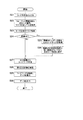
次に、図2の情報コード読取装置10によって図1、図5右図等に示す情報コード100を読み取る場合の基本的な処理について説明する。図9の読取処理は、例えばユーザによって所定操作(例えば、操作スイッチ42の操作等)がなされたときに実行されるものであり、まず、図9のS21に示すように、情報コード100の撮像し、当該情報コード100の画像を取得すると共に、情報コード100の外形を検出する。具体的には、位置検出パターン104を公知の方法(QRコードで行われる公知の方法)で検出し、QRコードで行われる公知の方法で情報コード100の外形を検出する。
(Information code reading process)
Next, a basic process in the case of reading the
S21の後には、情報コード100の所定位置の情報(フォーマット情報)を解読し、情報コード100の種別及びマスク訂正レベルを取得する(S22)。上述したように、所定位置105に記録された情報を上述の特定マスク(額縁QR用マスク)に基づいてマスク処理を解除して解読したときにチェックデジットが合う場合には、情報コード100の種別(空き領域110を有する種別)であることを特定することができ、フォーマット情報に含まれる誤り訂正レベル及びマスク番号も取得できることとなる。そして、S22で取得されたフォーマット情報に含まれるマスク番号に基づいてコード全体(具体的には、コードワードの領域)のマスクを解除する(S23)。そして、読み取り対象が空き領域110を有する情報コード100である場合(即ち、上述の特定マスク(額縁QR用マスク)によってマスク解除が成功した場合)、S24にてYesに進み、データワードの先頭に設けられたヘッダーデータ(額縁QRヘッダー:図3)を解読することで、元のコードサイズ(他種コード120の型番)を特定し(S25)、図5と同様の配置変換表に従って、図5右図に示すような情報コード100から図5左図に示すような元のコード(他種コード120)の配置に戻す(S26)。具体的には、情報コード100の各配置候補位置のコードワードを、配置変換表において各配置候補位置に対応付けられている他種コード120内での配置位置に配置し直す。そして、S24でNoの場合又はS26の後には、セル配置(S24でNoに進む場合、読取対象のQRコードのセル配置であり、S26の後の場合、S26で配置された他種コード120のセル配置)から、記録されている各コードワードを特定・作成する(S27)。そして、誤り訂正符号記録領域の誤り訂正コードワードに基づいて公知の方法で誤り訂正計算を実施し、データ記録領域のコードワードを解読する(S29)。そして、S29で解読したデータ(解読対象データ)を表示部での表示、データ送信、印刷などによって出力する(S30)。なお、S30の処理としては、S29で解読したデータをそのままを出力してもよく、他の処理を付加してもよい。なお、ここでは、空き領域110内の解析やデータの具体的な出力方法は省略しており、これらについては、後に詳述する。
After S21, the information (format information) at a predetermined position of the
本構成では、制御回路40が「判別部」の一例に相当し、撮像部によって情報コード100が撮像された場合に、コード領域の所定位置105が特定のフォーマット構成であるか否かを判別するように機能する。具体的には、所定位置105に所定種類のマスクパターン(特定マスク)が反映されているか否かを判別するように機能する。
In this configuration, the
制御回路40は、「解読部」の一例に相当し、撮像部によって情報コード100が撮像された場合に、データ記録領域及び誤り訂正符号記録領域の内容に基づいてデータ記録領域に記録されたデータを解読するように機能し、具体的には、判別部によって所定位置105が特定のフォーマット構成であると判別された場合(より詳しくは、所定位置105に所定種類のマスクパターンが反映されている場合)に、対応情報記録部に記録された対応情報(配置変換表)に基づいてコード領域内の各データワードの位置を特定し、解読対象データを解読するように機能する。
The
なお、配置変換表は、「対応情報」の一例に相当し、コード領域において各配置位置で表される各順番のデータワードを、情報コード100とは異なる他種コード120において予め定められた方式(例えば公知規格等で定められた方式など)で表現する場合の当該他種コード120内での各対応位置を定める情報として構成されている。そして、解読部に相当する制御回路40は、判別部によって所定位置105が特定のフォーマット構成であると判別された場合、コード領域の各配置位置で表される各順番のデータワードを、上記対応情報(配置変換表)で定められる他種コード120内での各対応位置に置換した構成で当該他種コード120を解読するように機能する。
The arrangement conversion table corresponds to an example of “correspondence information”, and a data word in each order represented by each arrangement position in the code area is determined in advance in another
(特徴的構成)
次に、拡張現実マーカなどの特徴的構成について説明する。
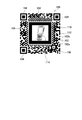
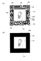
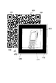
情報コード100は、図10のように、空き領域110(画像領域)内に所定形状の基準図形(拡張現実マーカ112)を配置した構成となっている。拡張現実マーカ112は、例えば、空き領域110の外縁に沿って配置され、黒色等の暗色の四角形枠(正方形枠又は長方形枠)として構成されており、枠幅は、セルの幅よりも大きくなっている。
(Characteristic configuration)
Next, a characteristic configuration such as an augmented reality marker will be described.
As shown in FIG. 10, the
また、情報コード100のコード領域内には、拡張現実マーカ112が表示される領域以外の位置に、表示候補の拡張現実画像に対応した画像又は情報の少なくともいずれかを示す関連内容が表示されるようになっている。図10の例では、四角形枠として構成される拡張現実マーカ112(ARマーカ)の内側に、表示候補の拡張現実画像と同一の物品を示す関連画像114が示されており、どのような物品が拡張現実画像として重畳表示されるかを、コードの内容から視覚的に把握できるようになっている。
In addition, in the code area of the
情報コード100のデータ記録領域には、拡張現実画像が蓄積された管理装置90に対応したアドレス情報(URLなど)が記録されている。本構成では、図11のように、情報端末として構成される読取装置10と管理装置90(サーバ)とがインターネット回線、無線LAN回線、その他の通信回線などを介して通信可能とされており、読取装置10は、情報コード100のデータ記録領域からアドレス情報(URLなど)を読み取ることで管理装置90(サーバ)のアドレスを特定することができ、これにより管理装置90(サーバ)と情報の送受信ができるようになっている。
In the data recording area of the
また、情報コード100のデータ記録領域には、表示対象の拡張現実画像を特定する特定情報が記録されている。例えば、管理装置90(サーバ)には、拡張現実画像となる複数の候補画像が、それぞれの候補画像に対応する識別情報と紐付けて登録されており、識別情報が特定されれば、その識別情報に対応する候補画像を拡張現実画像として読み出すことができるようになっている。そして、情報コード100のデータ記録領域には、管理装置90において複数の候補画像に紐付けられているいずれかの識別情報が特定情報として記録されており、これにより、重畳表示される拡張現実画像が特定されている。
In the data recording area of the
図11、図12は、拡張現実表示の運用例を示している。
このような情報コード100を用いて拡張現実表示を行う場合、まず、図2に示す読取装置10の受光センサ23(撮像部)により、読取装置10の外部に設定された撮像範囲(受光センサ23によって受光可能な範囲)の実画像を撮像する。このとき、例えば、受光センサ23で撮像される撮像画像をリアルタイムに液晶表示器46(図2、図11等)に表示する。なお、本構成では、受光センサ23が撮像部の一例に相当し、情報コード読取装置10の装置外に設定される撮像範囲(受光センサ23で受光可能となる視野範囲)の実画像を撮像するように機能する。また、液晶表示器46が表示部の一例に相当し、撮像部によって撮像される撮像範囲の実画像を表示するように機能する。
11 and 12 show an operation example of the augmented reality display.
When the augmented reality display is performed using such an
そして、受光センサ23(撮像部)によって撮像される実画像に情報コード100の画像が含まれる場合、その情報コード100の読み取りを行う(図11の(1)を参照)。情報コード100の読み取り方法は、図9等を参照して上述した通りである。情報コード100のデータ記録領域には、管理装置90(サーバ)のアドレス情報(URLやメールアドレス等)が記録され、且つ拡張現実画像を特定する特定情報(管理装置90に登録されたいずれかの識別情報)が記録されているため、読取装置10は、情報コード100の読み取りによってこれらの情報を取得する。
When the image of the
読取装置10は、このようにアドレス情報及び特定情報を取得した場合、取得したアドレス情報に基づいて管理装置90にアクセスし、取得した特定情報(拡張現実画像を特定する情報)に対応する拡張現実画像を要求する(図11の(2)を参照)。例えば、管理装置90(サーバ)に、拡張現実画像(オブジェクト画像)91a、91b、91cのような候補画像が三次元画像データとして登録されており、読取装置10が情報コード100のデータ記録領域から取得した特定情報(拡張現実画像を特定する情報)が拡張現実画像91aを特定する識別情報(管理装置90において、拡張現実画像91aと対応付けて登録された画像番号などの識別情報)である場合、読取装置10は、この特定情報を管理装置90に送信すると共に、拡張現実画像を要求するコマンドを送信することで、この拡張現実画像91aを要求することになる。この場合、管理装置90(サーバ)は、要求コマンドと共に送信されてきた特定情報(識別情報)に対応付けて当該管理装置90に登録されている拡張現実画像91aの三次元画像データを、その要求コマンドの送信元の読取装置10に送信する(図11の(3)を参照)。
When the
本構成では、図2の制御回路40がアドレス情報取得部の一例に相当し、情報コード100のデータ記録領域からアドレス情報を取得するように機能し、更に、要求部の一例に相当し、アドレス情報取得部によって取得されたアドレス情報で特定される送信先に対し、拡張現実画像を要求するように機能する。また、図2の制御回路40は、特定情報取得部の一例に相当し、データ記録領域から特定情報(重畳表示される拡張現実画像を特定する情報)を取得するように機能している。
In this configuration, the
一方、読取装置10は、図11の(1)で情報コード100を読み取る際に、情報コード100のコード画像の中から空き領域110を特定する。上述したように、情報コード100のデータ記録領域には、空き領域110(画像領域)の位置(画像領域位置)を特定し得る情報(第2情報に相当する「画像領域位置情報」)が記録されているため、この情報に基づいてコード画像の中から空き領域110の画像位置を特定する。
On the other hand, when reading the
本構成では、図2の制御回路40が領域検出部の一例に相当し、受光センサ23(撮像部)によって撮像される実画像からコード領域の画像を検出するように機能し、更に、制御回路40は、空き領域特定部の一例に相当し、領域検出部によって検出されたコード領域の画像を解析し、空き領域110の位置を特定するように機能する。
In this configuration, the
そして、その特定された空き領域110の画像の中から拡張現実マーカ112を検出する(図12の(4)を参照)。拡張現実マーカ112の検出方法は、例えば、拡張現実技術で用いられる公知方法を用いればよく、画像の中から拡張現実マーカ112を検出できる方法であれば方法は特に限定されない。そして、拡張現実マーカ112を認識することで、当該拡張現実マーカ112の形状から姿勢を検出することができる。例えば、図12のように、撮像画像(表示画像)において拡張現実マーカ112が付される面と直交する方向をZ方向、拡張現実マーカ112の所定の一辺の方向をX方向、Z方向及びX方向と直交する方向をY方向とするように撮像画像(表示画像)内での座標系を特定する。
Then, the
本構成では、図2に示す読取装置10の制御回路40が画像処理部、マーカ検出部の一例に相当し、受光センサ23(撮像部)によって撮像される実画像(受光センサ23に映る実際の空間の画像)に情報コード100の画像が含まれる場合に、得られた情報コード100の撮像画像から基準図形(拡張現実マーカ112)を検出するように機能し、具体的には、空き領域特定部によって特定された空き領域110の中から拡張現実マーカ112の画像を検出するように機能する。
In this configuration, the
そして、管理装置90(サーバ)から取得した拡張現実画像(図11、図12の例では拡張現実画像(オブジェクト画像)91a)を、受光センサ23(撮像部)での撮像で得られた撮像範囲の実画像(撮像画像)で特定された上述の座標系の向きに合わせるように、その実画像(撮像画像)に重ね合わせる。なお、図12の例では、情報コード100の画像100’を含んだ実画像に拡張現実画像(オブジェクト画像)91aを重ね合わせて表示する例を示している。
The imaging range obtained by imaging the augmented reality image (in the example of FIGS. 11 and 12, the augmented reality image (object image) 91a) acquired from the management device 90 (server) by the light receiving sensor 23 (imaging unit). The actual image (captured image) is overlaid on the actual image (captured image) so as to match the orientation of the coordinate system specified above. In the example of FIG. 12, an example is shown in which an augmented reality image (object image) 91 a is superimposed and displayed on a real image including the
管理装置90(サーバ)に登録される拡張現実画像91a、91b、91cは、三次元画像データによって三次元の表示画像として構成されるものであり、各拡張現実画像毎に各拡張現実画像でのX方向、Y方向、Z方向が特定されているため、いずれかの拡張現実画像を実画像(撮像画像)に重ねて表示する場合、例えば、表示画像(撮像画像)内で、その拡張現実画像のX方向、Y方向、Z方向が拡張現実マーカ112で特定されるX方向、Y方向、Z方向に合うように重畳表示する。図12の例では、拡張現実画像91aで予め設定されたX方向、Y方向、Z方向が、拡張現実マーカ112の画像で特定される撮像画像(表示画像)でのX方向、Y方向、Z方向に合うように、実画像(撮像画像)に重ねて拡張現実画像91aを表示している。なお、拡張現実マーカ112と読取装置10との位置関係が変化することで、液晶表示器46にリアルタイムに表示される拡張現実マーカ112の姿勢が変化して表示画像(撮像画像)でのX方向、Y方向、Z方向が変化する場合、その変化した表示画像(撮像画像)のX方向、Y方向、Z方向と拡張現実画像91aのX方向、Y方向、Z方向とを合わせるように、三次元画像データに基づいて拡張現実画像91aの表示姿勢を変化させる。
The
なお、ここでは、読取装置10の受光センサ23(撮像部)で受光可能となる視野範囲(撮像範囲)の撮像画像(実画像)に拡張現実画像を重畳表示する例を示したが、実画像以外の他の画像を背景画像とし、この背景画像に拡張現実画像を重畳表示してもよい。或いは、実画像の一部を色彩や模様などの画像に変化させて背景画像とし、このような背景画像に拡張現実画像を重畳表示してもよい。
Here, an example in which an augmented reality image is superimposed and displayed on a captured image (real image) in a visual field range (imaging range) that can be received by the light receiving sensor 23 (imaging unit) of the
本構成では、図2の制御回路40が表示制御部の一例に相当し、マーカ検出部によって拡張現実マーカ112の画像が検出された場合に、受光センサ23(撮像部)によって撮像される実画像に対して拡張現実画像を重畳して液晶表示器46(表示部)に表示するように機能し、より具体的には、マーカ検出部によって拡張現実マーカ112の画像が検出された場合に、受光センサ23(撮像部)によって撮像される実画像に対して、空き領域110に表示される関連内容(図10等の例では関連画像114)に対応する表示候補の拡張現実画像(より詳しくは、特定情報取得部で取得された特定情報で特定される表示対象の拡張現実画像)を重畳して液晶表示器46(表示部)に表示するように機能する。
In the present configuration, the
本構成によれば、コード領域内を拡張現実マーカとして利用可能な情報コード100を読取対象として、液晶表示器46(表示部)に拡張現実画像を重畳表示し得る構成を実現できる。特に、コード画像に基づいて拡張現実マーカを特定できるようになるため、闇雲に拡張現実マーカを探す方法と比べ、拡張現実マーカをより識別しやすくなる。
According to this configuration, it is possible to realize a configuration in which an augmented reality image can be superimposed and displayed on the liquid crystal display 46 (display unit) with the
また、空き領域110が拡張現実マーカ112の表示領域とされた情報コード100を読取対象として、液晶表示器46(表示部)に拡張現実画像を重畳表示し得る構成を実現できる。特に、本構成では、領域検出部によってコード領域の画像を検出し、空き領域特定部によって空き領域110の位置を特定した上で拡張現実マーカ112を探し出すことができるため、拡張現実マーカ112が確実に存在する狭い領域に絞って効率的に検出を行うことができる。
Further, it is possible to realize a configuration in which the augmented reality image can be superimposed and displayed on the liquid crystal display 46 (display unit) with the
また、1つの情報コード100のコード領域から、拡張現実マーカ112と、拡張現実画像の画像データにアクセスするための情報とを抽出可能となり、読取装置10の外部に設けられた管理装置90に拡張現実画像の画像データが蓄積されるようなシステムであっても、複雑な操作を伴うことなく読取装置10に拡張現実画像の画像データを取得させやすくなる。
Further, the
また、情報コード100のコード領域から、拡張現実マーカ112と、表示対象の拡張現実画像を特定するための情報とを抽出可能となり、予定された拡張現実画像を表示する上で複雑な操作が抑えられる。また、同一のコード領域内の要素に基づく同時期の読み取りによって拡張現実マーカ112の認識と拡張現実画像の特定がなされるため、拡張現実マーカの認識と拡張現実画像の特定を別々に行うような構成と比べ、拡張現実マーカ112に対応付けて予定された画像(表示対象の拡張現実画像)をより迅速に且つより正確に表示できるようになる。
Further, the
また、コード領域内において予めなされている表示(表示対象の拡張現実画像に対応した画像又は情報の表示であり、図10の例では関連画像114の表示)に関連する拡張現実画像を重畳表示することができるため、利用者が読み取り前に拡張現実画像を把握或いは推測しやすい構成となり、利便性が一層高まる。なお、図10等では、表示対象の拡張現実画像に対応した画像として、拡張現実画像と同一物品の関連画像114を表示する例を示したが、表示する画像は同一物品でなくてもよく、表示対象の拡張現実画像(データ記録領域に記録された特定情報で特定される拡張現実画像)を簡略化した類似絵柄などであってもよい。或いは、表示対象の拡張現実画像の名称(物品名、人物名など)などを示す文字情報などであってもよい。
In addition, the augmented reality image related to the display in advance in the code area (the display of the image or information corresponding to the augmented reality image to be displayed and the display of the
[第2実施形態]
次に、第2実施形態について説明する。
第2実施形態の情報コード利用システムは、ハードウェア構成については第1実施形態と同一であり、上述した図1、図2のような構成が用いられる。
[Second Embodiment]
Next, a second embodiment will be described.
The information code utilization system of the second embodiment is the same as that of the first embodiment with respect to the hardware configuration, and the configuration shown in FIGS. 1 and 2 described above is used.
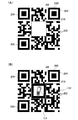
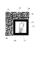
第2実施形態のシステムで用いられる情報コード100は、図13(A)のような構成となっており、この情報コード100は、空き領域110の外部の構成は第1実施形態の情報コード100と同一となっている。また、空き領域110の内部は、拡張現実マーカ112を省略した点以外は第1実施形態の情報コード100と同一である。本構成の情報コード100も、コード領域において、特定パターン領域及びデータ記録領域以外の位置に、セルによってデータ記録領域にデータを記録する方法とは異なる方法で情報又は画像の表示が可能な領域である空き領域110が、単一の前記セルのサイズよりも大きいサイズで設けられている。
The
そして、コード領域における空き領域110以外の外部領域(空き領域110の周囲領域)に、特定パターン領域及びデータ記録領域を構成するセルが配列された構成となっている。そして、この外部領域(空き領域110の周囲領域)が「拡張現実マーカに加工されるべき領域」となっている。 In the code area, cells constituting the specific pattern area and the data recording area are arranged in an external area other than the empty area 110 (a surrounding area of the empty area 110). This external area (the area around the empty area 110) is “an area to be processed into an augmented reality marker”.
本構成でも、図11、図12と同様の運用がなされる。なお、以下の説明では、図11、図12に示す情報コード100に代えて図13(A)の情報コード100が用いられ、拡張現実表示が行われる場合について説明する。
図13に示す情報コード100を用いて拡張現実表示を行う場合、第1実施形態と同様、図2に示す読取装置10の受光センサ23(撮像部)により、読取装置10の外部に設定された撮像範囲(受光センサ23によって受光可能な範囲)の実画像を撮像する。このとき、例えば、受光センサ23で撮像される撮像画像をリアルタイムに液晶表示器46(図2)に表示する。
Even in this configuration, the same operation as in FIGS. 11 and 12 is performed. In the following description, a case where the
When the augmented reality display is performed using the
そして、受光センサ23(撮像部)によって撮像される実画像に情報コード100の画像が含まれる場合、その情報コード100の読み取りを行う(図11の(1)と同様)。情報コード100の読み取り方法は、図9等を参照して上述した通りである。情報コード100のデータ記録領域には、管理装置90(サーバ)のアドレス情報(URLやメールアドレス等)が記録され、且つ拡張現実画像を特定する特定情報(管理装置90に登録されたいずれかの識別情報)が記録されているため、読取装置10は、情報コード100の読み取りによってこれらの情報を取得する。
When the image of the
読取装置10は、このようにアドレス情報及び特定情報を取得した場合、取得したアドレス情報に基づいて管理装置90にアクセスし、取得した特定情報(拡張現実画像を特定する情報)に対応する拡張現実画像を要求する(図11の(2)と同様)。この例でも、管理装置90(サーバ)に、拡張現実画像(オブジェクト画像)91a、91b、91cのような候補画像が三次元画像データとして登録されており、読取装置10が情報コード100のデータ記録領域から取得した特定情報(拡張現実画像を特定する情報)が拡張現実画像91aを特定する識別情報(管理装置90において、拡張現実画像91aと対応付けて登録された画像番号などの識別情報)である場合、読取装置10は、この特定情報を管理装置90に送信すると共に、拡張現実画像を要求するコマンドを送信することで、この拡張現実画像91aを要求することになる。この場合、管理装置90(サーバ)は、要求コマンドと共に送信されてきた特定情報(識別情報)に対応付けて当該管理装置90に登録されている拡張現実画像91aの三次元画像データを、その要求コマンドの送信元の読取装置10に送信する(図11の(3)と同様)。
本構成でも、図2の制御回路40がアドレス情報取得部、要求部、特定情報取得部の一例に相当する。
When the
Also in this configuration, the
一方、読取装置10は、図11の(1)で図13(A)の情報コード100を読み取る際には、この情報コード100のコード画像の中から空き領域110を特定する。上述したように、情報コード100のデータ記録領域には、空き領域110(画像領域)の位置(画像領域位置)を特定し得る情報(第2情報に相当する「画像領域位置情報」)が記録されているため、この情報に基づいてコード画像の中から空き領域110の画像位置を特定する。
On the other hand, when reading the
なお、情報コード100の読み取りの際には、特定パターン104に基づき、公知のQRコード(登録商標)の読み取りと同様の方法でコード領域の外縁が特定されている。そして、このように、受光センサ23(撮像部)で撮像された実画像(受光センサ23の視野範囲を実際に撮像した画像)の中から情報コード100のコード領域の外縁と、空き領域110の外縁とが特定できた場合、コード領域のうちの空き領域110の外部領域(即ち、情報コード100のコード領域の外縁と空き領域110の外縁とに囲まれる環状領域)のセル配列画像に対して所定の暗色化処理を行い、当該外部領域のセル配列画像を拡張現実マーカ112aの画像に加工する。セル配列画像に対する暗色化領域としては、例えば、公知の収縮領域によって画像の中で所定輝度以上の明色領域を収縮させ、所定輝度未満の暗色領域を膨張させるといった方法などが挙げられる。なお、このような収縮処理を複数回繰り返してもよい。或いは、情報コード100のコード領域の外縁と空き領域110の外縁とに囲まれる環状領域の全ての画素の輝度値を、その環状領域内の最小輝度値に置き換えるような処理であってもよい。また、これらの方法に限らず、情報コード100のコード領域の外縁と空き領域110の外縁とに囲まれる環状領域を図13(B)のように暗色化できる公知の画像処理方法であればよい。いずれの方法でも、空き領域110の外部領域(即ち、情報コード100のコード領域の外縁と空き領域110の外縁とに囲まれる環状領域)のセル配列画像が図13(B)のような拡張現実マーカ112aの画像に加工される。
When the
本構成では、情報コード読取装置10の制御回路40が外部領域特定部の一例に相当し、受光センサ23(撮像部)によって撮像される実画像に情報コード100の画像が含まれる場合に、外部領域(コード領域内における空き領域110の外側の領域)の位置を特定するように機能する。また、制御回路40は、画像加工部の一例にも相当し、外部領域特定部によって特定された外部領域のセル配列画像に対して所定の暗色化処理を行い、当該外部領域のセル配列画像を拡張現実マーカ112aの画像に加工するように機能する。
In this configuration, the
そして、受光センサ23で撮像された撮像画像(実画像)の一部(上記外部領域)を加工した加工画像において拡張現実マーカ112を認識することで、当該拡張現実マーカ112の形状から姿勢を検出することができる。例えば、図12と同様、撮像画像を加工した加工画像において拡張現実マーカ112aに加工される領域の面と直交する方向をZ方向、拡張現実マーカ112aの所定の一辺の方向をX方向、Z方向及びX方向と直交する方向をY方向とするように撮像画像を加工した加工画像内での座標系を特定する。なお、この場合、撮像画像の一部を拡張現実マーカ112aに加工した加工画像を液晶表示器46(表示部)に表示すればよい。
Then, the posture is detected from the shape of the
本構成では、図2に示す読取装置10の制御回路40が画像処理部、マーカ検出部の一例に相当し、受光センサ23(撮像部)によって撮像される実画像(受光センサ23に映る実際の空間の画像)に情報コード100の画像が含まれる場合に、得られた情報コード100の撮像画像から基準図形(拡張現実マーカ112a)を検出するように機能し、具体的には、画像加工部によって加工処理がなされた後の加工後画像から拡張現実マーカ112aの画像を検出するように機能する。
In this configuration, the
なお、このように拡張領域マーカ212が生成された後の画像の利用方法は第1実施形態と同一であり、本構成に係るシステムでも、第1実施形態の(特徴的構成)で説明した機能と同様の機能を持たせることができる。
具体的には、管理装置90(サーバ)から取得した拡張現実画像(図11、図12の例では拡張現実画像(オブジェクト画像)91a)を、上記加工画像(受光センサ23で撮像した実画像(撮像画像)の一部を拡張現実マーカ112aに加工した画像)で特定された上述の座標系の向きに合わせるように、その拡張現実マーカ112aに重ね合わせる。つまり、この例では、受光センサ23で撮像した実画像(撮像画像)に対し、拡張現実マーカ112aの画像と拡張現実画像(オブジェクト画像)91aが重畳されることになる。
The method of using the image after the extended area marker 212 is generated in this way is the same as that in the first embodiment, and the system described in the first embodiment (characteristic configuration) is also used in the system according to this configuration. Can have the same function.
Specifically, an augmented reality image (augmented reality image (object image) 91a in the examples of FIGS. 11 and 12) acquired from the management device 90 (server) is processed image (actual image (image captured by the light receiving sensor 23) ( A portion of the captured image) is superimposed on the
本構成でも、図12と同様、管理装置90(サーバ)に登録される拡張現実画像91a、91b、91cは、三次元画像データによって三次元の表示画像として構成されるものであり、各拡張現実画像毎に各拡張現実画像でのX方向、Y方向、Z方向が特定されているため、いずれかの拡張現実画像を拡張現実マーカ112aの画像と共に実画像(撮像画像)に重ねて表示する場合、例えば、表示画像(加工画像)内で、その拡張現実画像のX方向、Y方向、Z方向が拡張現実マーカ112aで特定されるX方向、Y方向、Z方向に合うように重畳表示する。なお、拡張現実マーカ112と読取装置10との位置関係が変化したときには、液晶表示器46にリアルタイムに表示される加工画像において拡張現実マーカ112aの姿勢も上記外部領域の姿勢に合わせて変化させればよい。そして、拡張現実マーカ112aの姿勢が変化して表示画像(加工画像)でのX方向、Y方向、Z方向が変化する場合、その変化した表示画像(加工画像)のX方向、Y方向、Z方向と拡張現実画像91aのX方向、Y方向、Z方向とを合わせるように、三次元画像データに基づいて拡張現実画像91aの表示姿勢を変化させる。
Also in this configuration, as in FIG. 12, the
なお、ここでは、読取装置10の受光センサ23(撮像部)で受光可能となる視野範囲(撮像範囲)の撮像画像(実画像)に拡張現実画像を重畳表示する例を示したが、実画像以外の他の画像を背景画像とし、この背景画像に拡張現実画像を重畳表示してもよい。或いは、実画像の一部を色彩や模様などの画像に変化させて背景画像とし、このような背景画像に拡張現実画像を重畳表示してもよい。
Here, an example in which an augmented reality image is superimposed and displayed on a captured image (real image) in a visual field range (imaging range) that can be received by the light receiving sensor 23 (imaging unit) of the
本構成では、図2の制御回路40が表示制御部の一例に相当し、マーカ検出部によって拡張現実マーカ112aの画像が検出された場合に、撮像部によって撮像される実画像又は所定の背景画像に対して拡張現実画像を重畳して液晶表示器46(表示部)に表示するように機能する。
In the present configuration, the
本構成によれば、第1実施形態と同様の効果が得られる。
また、本構成では、空き領域110以外の外部領域(特定パターンやデータ記録領域が設けられた領域)を、拡張現実マーカ112aに加工されるべき領域として利用することができ、外部領域を、情報コードの基本機能を実現するための領域として利用しつつ、拡張現実マーカを表すための領域としても利用できるようになり、スペース的な利点が非常に大きくなる。更に、空き領域110については、データ記録領域の影響や拡張現実マーカの影響を抑えて自由に表現しやすくなるため、情報コードを利用する上での利便性が一層高まる。
According to this configuration, the same effect as in the first embodiment can be obtained.
In this configuration, an external area other than the empty area 110 (an area provided with a specific pattern or a data recording area) can be used as an area to be processed into the
本構成では、上記外部領域を構成するデータ記録領域のセル配列については、暗色セルが多くなるように配列することが望ましい。具体的方法としては、データ記録領域のうち、データの読み出しに関係しない残余領域(フォーマット情報、解読対象データを表現するコードワード、誤り訂正符号を表現するコードワード以外の残余のコードワード)のセル配列を暗色セルのみで構成するといった方法などが挙げられる。なお、データ記録領域において暗色セルを多くするための技術としては、例えば、特開2008−52588、特開2009−163720、特開2012−238342などの技術を用いてもよい。 In this configuration, it is desirable that the cell arrangement of the data recording area constituting the external area is arranged so that there are many dark cells. As a concrete method, cells in the remaining area (format information, code word representing data to be decoded, remaining code word other than code word representing error correcting code) in the data recording area not related to data reading For example, the array may be composed of only dark cells. As a technique for increasing the number of dark cells in the data recording area, for example, techniques such as Japanese Unexamined Patent Application Publication Nos. 2008-52588, 2009-163720, and 2012-238342 may be used.
[第3実施形態]
次に、第3実施形態について説明する。
第3実施形態の情報コード利用システムは、ハードウェア構成については第1実施形態と同一であり、上述した図1、図2のような構成が用いられる。
[Third Embodiment]
Next, a third embodiment will be described.
The information code utilization system of the third embodiment is the same as that of the first embodiment in terms of hardware configuration, and the configuration as shown in FIGS. 1 and 2 described above is used.
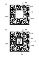
第2実施形態の情報コード利用システムでは、情報コード生成装置2(図1等参照)により図14(B)のような情報コード200を生成する。この構成でも、コード領域の内部に、予め定められた形状の特定パターン204が配置される特定パターン領域と、複数種類のセルによってデータを記録するデータ記録領域とを設け、コード領域の内部において、特定パターン領域以外の位置に、データ記録領域にデータを記録する方法とは異なる方法で、データの記録又はデザインの表示の少なくともいずれかが可能となる空き領域210を、単一のセルのサイズよりも大きい所定サイズで設けている。
In the information code utilization system of the second embodiment, the
この構成では、空き領域210の構成以外は、公知のQRコード(登録商標)として構成されており、まず、図14(A)のように、コード領域の内部に、特定パターン領域と、データ記録領域と、複数種類のセルによって誤り訂正符号を記録する誤り訂正符号記録領域とを設けている。なお、データ記録領域でのデータコードワードの記録方法及び誤り訂正符号記録領域での誤り訂正コードワードの記録方法は公知のQRコード(登録商標)と同様であり、例えば、JISX0510で規定される方式でコード領域内の位置検出パターン(特定パターン204)の配置、データ記録領域におけるデータコードワードの配置、誤り訂正符号記録領域での誤り訂正コードワードの配置が定められている。
In this configuration, except for the configuration of the
但し、図14(A)のように、一部領域のコードワードを、白セルのみによって表現されるコードワードとして構成した情報コード200’を生成し、このように白セルのみによって表現される領域ARを空き領域210として、図14(B)のように、この空き領域210内に図形、模様、色彩又はこれらの結合からなるデザイン、又は1又は複数の記号によって表わされる情報の少なくともいずれかを表示している。図14(B)のように空き領域210内に第1実施形態と同様の画像(拡張現実マーカ112及び関連画像114)を表示した場合、図14(A)のような本来のデータ表示とは異なった構成になるが、この空き領域210でのデータの誤りは、誤り訂正符号記録領域に記録された誤り訂正符号を用いて公知の誤り訂正を行えばよい。
However, as shown in FIG. 14A, an
また、図14(B)に示す情報コード200では、空き領域210の位置が予め特定されるため、空き領域210内にデザインや情報を付加して表示する場合にはこの表示による誤り位置が予め分かっていることになる。従って、空き領域210の位置を誤り位置として消失訂正を行うように誤り訂正符号記録領域の誤り訂正符号を構成することもできる。この場合、空き領域210の位置を示す情報を予めデータ記録領域に記録しておいたり、或いは、予め読取装置10(図1)内に記憶しておくことで、読取時に読取装置10が空き領域210の位置(即ち、誤りが生じているデータコードワードの位置)を特定することができるようになり、読取装置10は、このように位置が特定された空き領域210に存在するデータコードワードの誤りを訂正するように、誤り訂正符号記録領域に記録された誤り訂正符号を用いて消失訂正を行うようにすればよい。
In addition, in the
また、この構成では、データ記録領域に記録されるデータの内、解読対象データの終わりを示す終端子よりも前に配置されるデータ(出力対象となる解読対象データ)については、空き領域210の外側に配置し、終端子よりも後に配置される埋め草コードワード(解読対象とならないデータ)の領域を空き領域210とするとよい。本構成では、例えば、この埋め草コードワードの領域を全て白セルのみで表示するようにしている。
Further, in this configuration, the data arranged in the data recording area before the end terminal indicating the end of the decoding target data (decoding target data to be output) is stored in the
そして、このように構成される情報コード200の空き領域210に、空き領域110(図10)と同様の画像(拡張現実マーカ112及び関連画像114)を表すことで、図10と同様の機能を有する情報コード200を構成することができる。なお、情報コード200の利用方法は第1実施形態と同様であり、本構成に係るシステムでも、第1実施形態の(特徴的構成)で説明した機能と同様の機能を持たせることができる。
Then, by displaying the same image (augmented
[第3実施形態]
次に、第3実施形態について説明する。
第3実施形態の情報コード利用システムも、ハードウェア構成については第1実施形態と同一であり、上述した図1、図2のような構成が用いられる。
[Third Embodiment]
Next, a third embodiment will be described.
The information code utilization system of the third embodiment is the same as that of the first embodiment in terms of hardware configuration, and the configuration as shown in FIGS. 1 and 2 is used.
第3実施形態の情報コード利用システムでは、情報コード生成装置2(図1等参照)により図15(B)のような情報コード300を生成する。この構成でも、コード領域の内部に、予め定められた形状の特定パターン(L字状のアライメントパターン304a及び明色セルと暗色セルが1セルずつ交互に配置され、コード領域の境界に沿ったL字状の領域を構成するタイミングセル304b)が配置される特定パターン領域と、複数種類のセルによってデータを記録するデータ記録領域とを設け、コード領域の内部において、特定パターン領域以外の位置に、データ記録領域にデータを記録する方法とは異なる方法で、データの記録又はデザインの表示の少なくともいずれかが可能となる空き領域310を、単一のセルのサイズよりも大きい所定サイズで設けている。
In the information code utilization system of the third embodiment, the
この構成では、空き領域310の構成以外は、公知のデータマトリックスコードとして構成されており、まず、図15(A)のように、コード領域の内部に、特定パターン領域と、データ記録領域と、複数種類のセルによって誤り訂正符号を記録する誤り訂正符号記録領域とを設けている。なお、データ記録領域でのデータコードワードの記録方法及び誤り訂正符号記録領域での誤り訂正コードワードの記録方法は公知のデータマトリックスコードと同様であり、コード領域内のアライメントパターン304aやタイミングセル304bの配置、データ記録領域におけるデータコードワードの配置、誤り訂正符号記録領域での誤り訂正コードワードの配置は、例えばECC200バージョンに従って定められている。
In this configuration, except for the configuration of the
但し、図15(A)のように、一部領域のコードワードを、白セルのみによって表現されるコードワードとして構成した情報コード300’を生成し、このように白セルのみによって表現される領域ARを空き領域310として、図15(B)のように空き領域310内に第1実施形態と同様の画像(拡張現実マーカ112及び関連画像114)を表示した場合、図15(A)のような本来のデータ表示とは異なった構成になるが、この空き領域310でのデータの誤りは、誤り訂正符号記録領域に記録された誤り訂正符号を用いて公知の誤り訂正を行えばよい。
However, as shown in FIG. 15A, an
また、図15(B)に示す情報コード300では、空き領域310の位置が予め特定されるため、空き領域310内にデザインや情報を付加して表示する場合にはこの表示による誤り位置が予め分かっていることになる。従って、空き領域310の位置を誤り位置として消失訂正を行うように誤り訂正符号記録領域の誤り訂正符号を構成することもできる。この場合、空き領域310の位置を示す情報を予めデータ記録領域に記録しておいたり、或いは、予め読取装置10(図1)内に記憶しておくことで、読取時に読取装置10が空き領域310の位置(即ち、誤りが生じているデータコードワードの位置)を特定することができるようになり、読取装置10は、このように位置が特定された空き領域310に存在するデータコードワードの誤りを訂正するように、誤り訂正符号記録領域に記録された誤り訂正符号を用いて消失訂正を行うようにすればよい。
In the
そして、このように構成される情報コード300の空き領域310に、空き領域110(図10)と同様の画像(拡張現実マーカ112及び関連画像114)を表すことで、図10と同様の機能を有する情報コード300を構成することができる。なお、情報コード300の利用方法は第1実施形態と同様であり、本構成に係るシステムでも、第1実施形態の(特徴的構成)で説明した機能と同様の機能を持たせることができる。
Then, by displaying the same image (augmented
[第4実施形態]
次に、第4実施形態について図16等を参照して説明する。
第4実施形態は、第1実施形態と同様の空き領域を設ける構成であるが、空き領域の特定のみが第1実施形態と異なっている。なお、図16の例では、一部の特定パターン以外の領域の具体的内容は省略して示しており、実際は、空き領域410外の外部領域に明色セルや暗色セルが配置されることになる。また、空き領域410内は、例えば第1実施形態の空き領域110(図10等)と同様の画像が表示される。
[Fourth Embodiment]
Next, a fourth embodiment will be described with reference to FIG.
The fourth embodiment is configured to provide a free area similar to that of the first embodiment, but only the specification of the free area is different from the first embodiment. In the example of FIG. 16, the specific contents of the areas other than some of the specific patterns are omitted, and in fact, light cells and dark cells are arranged in the external area outside the
本構成でも、情報コード400の種別において複数の型番が用意されており、型番毎にセルの行数及び列数、特定パターンの形状及び位置、フォーマット情報の位置、コードワードの候補位置(アドレス)が予め定められている。そして、生成装置2が情報コード400を生成する際には、型番情報をコード領域内の決められた位置(図16の例では予約領域107)に配置するようになっている。従って、読取装置10が情報コード400を読み取る際には、情報コード400のコード画像を解析し、所定位置に配置された型番情報を読み取ることで、情報コード400のセルの行数及び列数、特定パターンの形状及び位置、フォーマット情報の位置、コードワードの候補位置(アドレス)を把握できることになる。
Also in this configuration, a plurality of model numbers are prepared for the type of the
情報コード400を生成する際には、予め用意された複数の型番の中からいずれかの型番を選択する。これにより、コード領域内の基本構成(特定パターン104の位置、セルの行数及び列数、コードワードの候補位置)が決定する。例えば、図16に示す構成の型番では、29行29列のセル配列となっており、予め定められた3つの角部に、QRコード(登録商標)の切り出しシンボルと同一の構造の特定パターン104が配置されるようになっている。そして、特定パターン104の近くの所定位置に、フォーマット情報を記録する領域(所定位置105)が設けられている。また、29行29列のマトリックス領域において、特定パターン104及び所定位置105以外の位置に、予めコードワードの候補位置が定められており、各候補位置に0〜67までのアドレスが割り当てられている。このように、型番に対応する構成で予めコード領域内の構成が規定されているため、型番が特定されれば、どの順番のコードワードがどの位置に配置されるかを特定することが可能となる。なお、決定した型番の情報は、その型番の配列において予め定められた固定位置に記録される。例えば図16の例では、所定種類のハッチングで特定される領域107に型番の情報が記録されるようになっている。
When generating the
そして、型番が決定し、コード領域内の基本構成が決定した後には、空き領域の形状及び位置を決定する。空き領域の形状の決定方法は、例えば、予め用意された複数の候補形状の中から選定する方式で決定してもよく、或いは、情報コード生成装置2に対して外部から入力された形状指定情報に従った形状に設定する方式で決定してもよい。或いは、決められた固定形状のみに決定してもよい。また、空き領域の位置については、予め決められた固定位置に決定してもよく、ユーザが位置を指定する情報を入力することで、その位置に決定するようにしてもよい。
After the model number is determined and the basic configuration in the code area is determined, the shape and position of the empty area are determined. The method for determining the shape of the vacant area may be determined by, for example, a method of selecting from a plurality of candidate shapes prepared in advance, or shape designation information input from the outside to the information
そして、空き領域が決定した後には、決定された空き領域の位置から外れるコードワードの候補位置に、データ記録領域のコードワード及び誤り訂正符号記録領域のコードワードをそれぞれ配置する構成で情報コード400を生成する。例えば、図16のような構成の型番では、3つの角部に特定パターン104が配置され、これら特定パターン104の位置を基準として、0〜67の番号が付された68個のコードワードの候補位置が予め規定されている。このようなレイアウトにおいて、図16のように空き領域410が決定した場合、少なくとも一部が空き領域410内に入るコードワードの候補位置を配置対象位置から除外し、その除外されたコードワードの位置を飛ばすようにして、順番にコードワードを配置する。例えば、図16の例では、50、51番、53、54番、60〜67番のコードワードの候補位置に入り込むように空き領域410が設定されているため、これら50、51番、53、54番、60〜67番のコードワードの候補位置にはコードワードを配置しないようにする。即ち、0〜49番の位置に順番にコードワードを配置した後、50、51番を飛ばして52番の位置にコードワードを配置し、その後、53、54番を飛ばして55〜59番の位置にコードワードを順番に配置することになる。このようにすれば、解読対象データを符号化したデータコードワードと、誤り訂正符号を表す誤り訂正コードワードとを、空き領域410から外れた候補位置に確実に配置することができる。
After the vacant area is determined, the
このように特定パターン領域(特定パターン104やその他の特定パターンの領域)、フォーマット領域(所定位置105)、型番領域107、各コードワード領域などを決定した後には、空き領域410の具体的な内容を決定する。この情報コード400でも、空き領域410に、空き領域110(図10)と同様の画像(拡張現実マーカ112及び関連画像114)を表すことで、図10と同様の機能を有する情報コード400を構成することができる。なお、情報コード400の利用方法は第1実施形態と同様であり、本構成に係るシステムでも、第1実施形態の(特徴的構成)で説明した機能と同様の機能を持たせることができる。
After determining the specific pattern area (
[他の実施形態]
本発明は上記記述及び図面によって説明した実施形態に限定されるものではなく、例えば次のような実施形態も本発明の技術的範囲に含まれる。
[Other Embodiments]
The present invention is not limited to the embodiments described with reference to the above description and drawings. For example, the following embodiments are also included in the technical scope of the present invention.
図1等の構成では、情報コード生成装置2と情報コード読取装置10が別々の装置として構成された例を示しているが、情報コード生成装置2が情報コード読取装置10として構成されていてもよい。
1 and the like show an example in which the information
第1実施形態では、他種コードとしてQRコードを例に挙げ、情報コード100で用いる特定パターンとしてQRコードの特定パターンを例に挙げたが、これ以外の種類の二次元コードを用いてもよい。例えば、他種コードとしてデータマトリックスコードを用い、情報コード100で用いる特定パターンをデータマトリックスコードの特定パターンとしてもよい。
In the first embodiment, the QR code is exemplified as the other type code, and the specific pattern of the QR code is exemplified as the specific pattern used in the
図5のように設定した配置変換表における対応関係は、図7のように任意に変更することができる。例えば、情報コード生成装置2、情報コード読取装置10において図5のように設定されていた配置変換表を図7のように変更した場合、生成される情報コード100では、22〜26番目のコードワードの配置が、図5右図のような配置(22〜26番の配置候補位置に記録する配置)から図7右図のような配置(42〜46番の配置候補位置に記録する配置)に変更され、これにより空き領域110の位置や形状も変化することになる。つまり、この構成では、配置変換表を調整することで空き領域110の位置や形状を調整することができ、空き領域を構成する上での自由度をより高めることができる。
The correspondence in the arrangement conversion table set as shown in FIG. 5 can be arbitrarily changed as shown in FIG. For example, when the arrangement conversion table set as shown in FIG. 5 in the information
第1実施形態等では、情報コード100内に、情報入力領域の位置を示す位置データ(例えば、図3に示す画像領域位置情報など)を含ませるようにしていたが、このような例に限られない。例えば、情報コード生成装置2が、空き領域において予め定められた所定位置に画像領域を配置するように情報コードを生成する構成であってもよい。この場合、所定位置を特定する情報(図3に示す画像領域位置情報などの情報)が記憶部5に記憶されていればよい。また、この場合、情報コード読取装置10には、情報コード生成装置2と同様、所定位置を特定する特定情報(図3に示す画像領域位置情報などの情報)をメモリ35に記憶しておけばよい。そして、情報コード読取装置10では、図9のS45において、メモリ35からこのような特定情報を読み出して情報入力領域を特定した上で、それ以降の処理を行えばよい。また、この場合、図3に示す画像領域位置情報は、ヘッダデータに含めなくてもよい。
In the first embodiment and the like, the position data indicating the position of the information input area (for example, the image area position information shown in FIG. 3) is included in the
本発明は、上述したいずれか1又は複数若しくは全ての情報コードを表示し得る表示装置として構成することもできる。また、上述したいずれか1又は複数若しくは全ての情報コードを印刷し得る印刷装置として構成することもできる。更に、上述したいずれか1又は複数若しくは全ての情報コードを生成するためのコンピュータ読取可能なプログラムとして構成することもできる。また、上述した1又は複数若しくは全ての情報コードを生成するためのプログラムを記録した記録媒体として構成することもできる。更に、上述した1又は複数若しくは全ての情報コードが付された情報コード媒体(印刷物、ダイレクトマーキング等によって構成された形成物など)として把握することもできる。また、上述した1又は複数若しくは全ての情報コードが表示された表示画像として把握することもできる。
上記実施形態では、「コード領域」の一例を示したが、「コード領域」は、情報コードを構成する複数種類のセルを全て含む最小の正方形領域又は長方形領域であればよく、コード領域の外縁部の一部にセルが配列されていなくてもよい。例えば、図17の情報コード500のように、空き領域510がコード領域の周縁部に隣接して形成されていてもよい。この場合、情報コード500を構成する複数種類のセルを全て含む最小の正方形領域又は長方形領域の外縁(コード領域の外縁)は、一点鎖線ARのようになり、空き領域510の外縁は、例えば二点鎖線AR2のようになる。また、認識対象となる画像領域(拡張現実マーカ112や関連画像114などを表示する領域)はコード領域内に少なくとも一部が存在すればよく、図18の画像領域AR3ように、残余の部分がコード領域外に存在するような構成であってもよい。図18のような例では、例えば、予め画像領域(拡張現実マーカ112や関連画像114などを表示する領域)AR3がどのような範囲になるかを特定する情報をデータ記録領域に記録しておけばよい。
The present invention can also be configured as a display device capable of displaying any one, plural, or all of the information codes described above. Moreover, it can also be configured as a printing apparatus capable of printing any one, plural or all of the information codes described above. Furthermore, it can also be configured as a computer-readable program for generating any one, plural or all of the information codes described above. Moreover, it can also be comprised as a recording medium which recorded the program for producing | generating the 1 or several or all the information code mentioned above. Furthermore, it can also be grasped as an information code medium (a printed material, a formed material formed by direct marking, etc.) to which one or a plurality of or all information codes are attached. Moreover, it can also be grasped as a display image on which one, a plurality, or all of the information codes described above are displayed.
In the above embodiment, an example of the “code area” is shown. However, the “code area” may be a minimum square area or rectangular area that includes all of a plurality of types of cells constituting the information code, and the outer edge of the code area. The cell may not be arranged in a part of the part. For example, as shown in the
上記実施形態では、コード領域内を構成する複数種類のセルとして、白色セルなどの明セルと黒色セルなどの暗セルを例示したが、コード領域内の特定パターン領域、データ記録領域、誤り訂正符号記録領域が、所定の濃度、輝度、色彩の第1種セルと、この第1種セルとは濃度、輝度、色彩のいずれかが異なる第2種セルに構成されていてもよい。或いは、コード領域内の特定パターン領域、データ記録領域、誤り訂正符号記録領域が、濃度、輝度、色彩のいずれかがそれぞれ異なる三種類以上のセルによって構成されていてもよい。 In the above embodiment, a bright cell such as a white cell and a dark cell such as a black cell are exemplified as a plurality of types of cells constituting the code area. However, a specific pattern area, a data recording area, and an error correction code in the code area are exemplified. The recording area may be configured as a first type cell having a predetermined density, luminance, and color, and a second type cell that is different in density, luminance, or color from the first type cell. Alternatively, the specific pattern area, the data recording area, and the error correction code recording area in the code area may be configured by three or more types of cells each having different density, luminance, or color.
上記実施形態では、コード領域内の特定パターン領域、データ記録領域、誤り訂正符号記録領域において、外形が正方形状のセルを複数配列した例を示したが、各セルの外形は正方形以外の四角形であってもよく、四角形以外の多角形や、円形、楕円形などの図形であってもよい。 In the above embodiment, an example in which a plurality of cells having a square outer shape are arranged in the specific pattern area, the data recording area, and the error correction code recording area in the code area has been described. However, the outer shape of each cell is a square other than a square. It may be a polygon other than a rectangle, or a figure such as a circle or an ellipse.
上記実施形態では、特定パターンの例として位置検出パターン104、タイミングパターン106、アライメントパターン108などを例示したが、データ記録領域及び誤り訂正符号記録領域の内容に関係なく固定のパターンとして構成される領域であれば、特定パターンを構成する図形は他の固有図形であってもよい。
In the above embodiment, the
上記実施形態では、空き領域内に拡張現実マーカを設ける例でも、空き領域の周囲を加工して拡張現実マーカとする例でも、拡張現実マーカ(ARマーカ)の例として、黒色等の暗色の四角形枠(正方形枠又は長方形枠)として構成された環状の拡張現実マーカを例示したが、拡張現実マーカの形状は上記実施形態の例に限られず、公知の様々な形状のものを用いることができる。 In the above embodiment, an example of providing an augmented reality marker in an empty area, an example of processing an area around the empty area to make an augmented reality marker, an example of an augmented reality marker (AR marker), a dark rectangle such as black Although an annular augmented reality marker configured as a frame (a square frame or a rectangular frame) has been illustrated, the shape of the augmented reality marker is not limited to the example in the above embodiment, and various known shapes can be used.
上記実施形態では、空き領域の一例を示したが、空き領域は、セルによってデータ記録領域にデータを記録する方法とは異なる方法で情報の表示又は画像の表示がなされる領域であればよい。例えば、第1実施形態のように、コードワードが全く配置されない領域として空き領域が構成されていてもよく、公知のQRコードなどにおいて、解読対象となるデータを表現するデータコードワードや誤り訂正符号を表現する誤り訂正コードワードが配置されず、埋め草コードワードが配置される領域を空き領域としてもよい。また、いずれの空き領域の場合でも、「セルによってデータ記録領域にデータを記録する方法とは異なる方法で情報の表示」を行うことができ、この情報の表示は、例えば、文字、数字、その他の記号などによって情報を表示してもよく、商標などによって特定の商品やサービスを表すような情報の表示方法であってもよい。また、空き領域では、「セルによってデータ記録領域にデータを記録する方法とは異なる方法では画像の表示」を行うことができ、この画像の表示は、図1のような拡張現実マーカ112や上述の関連画像114に限らず、様々な形状、模様、色彩、それらの結合などを表すことができる。
In the above embodiment, an example of the empty area is shown, but the empty area may be an area where information or an image is displayed by a method different from the method of recording data in the data recording area by the cell. For example, as in the first embodiment, a vacant area may be configured as an area where no code word is arranged, and in a known QR code or the like, a data code word or error correction code that represents data to be decoded The area where the error correction code word expressing the symbol is not arranged and the padding code word is arranged may be a free area. Also, in any free area, “information display by a method different from the method of recording data in the data recording area by cell” can be performed. Information may be displayed by a symbol or the like, or a method of displaying information that represents a specific product or service by a trademark or the like. Further, in the empty area, “image display by a method different from the method of recording data in the data recording area by cell” can be performed. This image display is performed by the
1…情報コード利用システム
2…情報コード生成装置
10…情報コード読取装置
23…受光センサ(撮像部)
40…制御回路(表示制御部、マーカ検出部、領域検出部、空き領域特定部、外部領域特定部、画像加工部、アドレス情報取得部、要求部、特定情報取得部)
46…液晶表示器(表示部)
90…管理装置
100,200,300,400,500、600…情報コード
102,202,302…セル
104,204…位置検出パターン(特定パターン)
110,210,310,410,510,610…空き領域
112,112a…拡張現実マーカ
304a…アライメントパターン(特定パターン)
304b…タイミングセル(特定パターン)
DESCRIPTION OF
40... Control circuit (display control unit, marker detection unit, region detection unit, empty region specification unit, external region specification unit, image processing unit, address information acquisition unit, request unit, specific information acquisition unit)
46 ... Liquid crystal display (display unit)
90 ...
110, 210, 310, 410, 510, 610 ...
304b ... Timing cell (specific pattern)
Claims (22)
前記コード領域の内部に、予め定められた形状の特定パターンが配置される特定パターン領域と、複数種類の前記セルによってデータを記録するデータ記録領域とを設け、
更に、前記コード領域内に、拡張現実マーカが表示される領域、又は前記拡張現実マーカに加工されるべき領域を設けることを特徴とする情報コード生成方法。 An information code generation method for generating, by an information code generation device, an information code in which cells serving as units for displaying information within a predetermined code area are arranged,
Inside the code area, a specific pattern area in which a specific pattern of a predetermined shape is arranged, and a data recording area for recording data by a plurality of types of cells,
Furthermore, an information code generation method characterized in that an area where an augmented reality marker is displayed or an area to be processed into the augmented reality marker is provided in the code area.
前記コード領域における前記空き領域以外の外部領域に、前記特定パターン領域及び前記データ記録領域を構成する前記セルを配列し、当該外部領域を前記拡張現実マーカに加工されるべき領域とすることを特徴とする請求項1に記載の情報コード生成方法。 In the code area, an empty area where information or an image can be displayed at a position other than the specific pattern area and the data recording area by a method different from the method of recording data in the data recording area by the cell. With a size larger than the size of the single cell,
The specific pattern area and the cells constituting the data recording area are arranged in an external area other than the empty area in the code area, and the external area is an area to be processed into the augmented reality marker. The information code generation method according to claim 1.
前記コード領域内において、前記拡張現実マーカが表示される領域、又は前記拡張現実マーカに加工されるべき領域以外の位置に、前記表示対象の拡張現実画像に対応した画像又は情報の少なくともいずれかを表示することを特徴とする請求項1から請求項4のいずれか一項に記載の情報コード生成方法。 In the data recording area, recording specific information for specifying an augmented reality image to be displayed,
In the code area, at least one of an image and information corresponding to the augmented reality image to be displayed at a position other than the area where the augmented reality marker is displayed or the area to be processed into the augmented reality marker. The information code generation method according to any one of claims 1 to 4, wherein the information code is displayed.
前記コード領域の内部に、予め定められた形状の特定パターンが配置される特定パターン領域と、複数種類の前記セルによってデータを記録するデータ記録領域とが設けられ、
更に、前記コード領域内に、拡張現実マーカが表示される領域、又は前記拡張現実マーカに加工されるべき領域が設けられていることを特徴とする情報コード。 An information code in which cells serving as units for displaying information are arranged in a predetermined code area,
A specific pattern area in which a specific pattern of a predetermined shape is arranged inside the code area, and a data recording area for recording data by a plurality of types of the cells are provided,
Furthermore, an information code characterized in that an area where an augmented reality marker is displayed or an area to be processed into the augmented reality marker is provided in the code area.
前記コード領域における前記空き領域以外の外部領域に、前記特定パターン領域及び前記データ記録領域を構成する前記セルが配列され、当該外部領域が前記拡張現実マーカに加工されるべき領域とされることを特徴とする請求項6に記載の情報コード。 In the code area, an empty area where information or an image can be displayed at a position other than the specific pattern area and the data recording area by a method different from the method of recording data in the data recording area by the cell. Is provided in a size larger than the size of a single said cell,
The cells constituting the specific pattern area and the data recording area are arranged in an external area other than the empty area in the code area, and the external area is an area to be processed into the augmented reality marker. 7. The information code according to claim 6, wherein
前記コード領域内において、拡張現実マーカが表示される領域、又は前記拡張現実マーカに加工されるべき領域以外の位置に、前記表示対象の拡張現実画像に対応した画像又は情報の少なくともいずれかが表示されていることを特徴とする請求項6から請求項9のいずれか一項に記載の情報コード。 Specific information for specifying the augmented reality image to be displayed is recorded in the data recording area, and in the code area, a position other than the area where the augmented reality marker is displayed or the area to be processed into the augmented reality marker The information code according to any one of claims 6 to 9, wherein at least one of an image and information corresponding to the augmented reality image to be displayed is displayed.
前記情報コードは、前記コード領域内に、拡張現実マーカが表示される領域、又は前記拡張現実マーカに加工されるべき領域が設けられた構成であり、
当該情報コード読取装置の装置外に設定される撮像範囲の実画像を撮像可能な撮像部と、
前記撮像部によって撮像される前記実画像を表示可能な表示部と、
前記撮像部によって撮像される前記実画像に前記情報コードの画像が含まれる場合に、前記情報コードの画像又は前記情報コードの画像を加工した加工画像から前記拡張現実マーカの画像を検出するマーカ検出部と、
前記マーカ検出部によって前記拡張現実マーカの画像が検出された場合に、前記撮像部によって撮像される前記実画像又は所定の背景画像に対して拡張現実画像を重畳して前記表示部に表示する表示制御部と、
を有することを特徴とする情報コード読取装置。 A cell as a unit for displaying information is arranged inside a predetermined code area, a specific pattern area in which a specific pattern having a predetermined shape is arranged inside the code area, and data by a plurality of types of the cells An information code reading device capable of reading an information code provided with a data recording area for recording,
The information code has a configuration in which an area where an augmented reality marker is displayed or an area to be processed into the augmented reality marker is provided in the code area,
An imaging unit capable of imaging a real image in an imaging range set outside the information code reader;
A display unit capable of displaying the real image captured by the imaging unit;
Marker detection that detects the image of the augmented reality marker from the image of the information code or a processed image obtained by processing the image of the information code when the image of the information code is included in the actual image captured by the imaging unit And
Display in which an augmented reality image is superimposed on the actual image or a predetermined background image captured by the imaging unit and displayed on the display unit when an image of the augmented reality marker is detected by the marker detection unit A control unit;
An information code reading device comprising:
前記撮像部によって撮像される前記実画像から前記コード領域の画像を検出する領域検出部と、
前記領域検出部によって検出された前記コード領域の画像を解析し、前記空き領域の位置を特定する空き領域特定部と、
を備え、
前記マーカ検出部は、前記空き領域特定部によって特定された前記空き領域の中から前記拡張現実マーカの画像を検出することを特徴とする請求項11に記載の情報コード読取装置。 The information code has an empty area in which the data to be decoded is not recorded by the cell at a position other than the specific pattern area and the data recording area within the code area. Is provided in a large size, and the augmented reality marker is displayed in the empty area,
An area detection unit for detecting an image of the code area from the actual image captured by the imaging unit;
Analyzing the image of the code area detected by the area detection unit, and specifying a position of the empty area;
With
12. The information code reading apparatus according to claim 11, wherein the marker detection unit detects an image of the augmented reality marker from the empty area specified by the empty area specifying unit.
前記撮像部によって撮像される前記実画像に前記情報コードの画像が含まれる場合に、前記外部領域の位置を特定する外部領域特定部と、
前記外部領域特定部によって特定された前記外部領域のセル配列画像に対して所定の暗色化処理を行い、当該外部領域の前記セル配列画像を拡張現実マーカの画像に加工する画像加工部と、
を備え、
前記マーカ検出部は、前記画像加工部によって加工処理がなされた後の加工後画像から前記拡張現実マーカの画像を検出することを特徴とする請求項11に記載の情報コード読取装置。 The information code can display information or an image by a method different from the method of recording data in the data recording area by the cell at a position other than the specific pattern area and the data recording area in the code area. An empty area that is an area is provided in a size larger than the size of a single cell, and the cells constituting the specific pattern area and the data recording area are provided in an external area other than the empty area in the code area. Is an array,
An external region specifying unit that specifies a position of the external region when the image of the information code is included in the real image captured by the imaging unit;
An image processing unit that performs a predetermined darkening process on the cell array image of the external region specified by the external region specifying unit, and processes the cell array image of the external region into an augmented reality marker image;
With
The information code reading device according to claim 11, wherein the marker detection unit detects an image of the augmented reality marker from a post-processing image that has been processed by the image processing unit.
前記データ記録領域から前記アドレス情報を取得するアドレス情報取得部と、
前記アドレス情報取得部によって取得された前記アドレス情報で特定される送信先に対し、拡張現実画像を要求する要求部と、
を有することを特徴とする請求項11から請求項13のいずれか一項に記載の情報コード読取装置。 The information code is recorded in the data recording area address information corresponding to a management device in which augmented reality images are stored,
An address information acquisition unit for acquiring the address information from the data recording area;
A request unit that requests an augmented reality image for a transmission destination specified by the address information acquired by the address information acquisition unit;
The information code reading device according to claim 11, further comprising:
前記データ記録領域から前記特定情報を取得する特定情報取得部を備え、
前記表示制御部は、前記マーカ検出部によって前記拡張現実マーカの画像が検出された場合に、前記撮像部によって撮像される前記実画像又は前記背景画像に対して、前記特定情報取得部で取得された前記特定情報で特定される前記表示対象の拡張現実画像を重畳して前記表示部に表示することを特徴とする請求項11から請求項14のいずれか一項に記載の情報コード読取装置。 The information code is a record in which specific information for specifying an augmented reality image to be displayed is recorded in the data recording area,
A specific information acquisition unit that acquires the specific information from the data recording area;
The display control unit is acquired by the specific information acquisition unit with respect to the real image or the background image captured by the imaging unit when an image of the augmented reality marker is detected by the marker detection unit. The information code reading device according to claim 11, wherein the augmented reality image to be displayed that is specified by the specifying information is superimposed and displayed on the display unit.
前記表示制御部は、前記マーカ検出部によって前記拡張現実マーカの画像が検出された場合に、前記撮像部によって撮像される前記実画像又は前記背景画像に対して、前記関連内容に対応する前記表示候補の拡張現実画像を重畳して前記表示部に表示することを特徴とする請求項11から請求項15のいずれか一項に記載の情報コード読取装置。 The information code is an image or information corresponding to the augmented reality image as a display candidate at a position other than the area where the augmented reality marker is displayed or the area to be processed into the augmented reality marker in the code area. The related content showing at least one of them is displayed.
The display control unit corresponds to the display corresponding to the related content with respect to the real image or the background image captured by the imaging unit when the image of the augmented reality marker is detected by the marker detection unit. The information code reading device according to any one of claims 11 to 15, wherein a candidate augmented reality image is superimposed and displayed on the display unit.
前記情報コード生成装置によって生成された前記情報コードを読み取る情報コード読取装置と、
を備えた情報コード利用システムであって、
前記情報コード生成装置は、前記コード領域の内部に、予め定められた形状の特定パターンが配置される特定パターン領域と、複数種類の前記セルによってデータを記録するデータ記録領域と、拡張現実マーカが表示される領域、又は前記拡張現実マーカに加工されるべき領域とを設けた構成で前記情報コードを生成し、
前記情報コード読取装置は、
当該情報コード読取装置の装置外に設定される撮像範囲の実画像を撮像可能な撮像部と、
前記撮像部によって撮像される前記実画像を表示可能な表示部と、
前記撮像部によって撮像される前記実画像に前記情報コードの画像が含まれる場合に、前記情報コードの画像又は前記情報コードの画像を加工した加工画像から前記拡張現実マーカの画像を検出するマーカ検出部と、
前記マーカ検出部によって前記拡張現実マーカの画像が検出された場合に、前記撮像部によって撮像される前記実画像又は所定の背景画像に対して拡張現実画像を重畳して前記表示部に表示する表示制御部と、
を有することを特徴とする情報コード利用システム。 An information code generation device for generating an information code in which cells serving as units for displaying information within a predetermined code area are arranged;
An information code reader for reading the information code generated by the information code generator;
An information code using system comprising:
The information code generation device includes a specific pattern area in which a specific pattern having a predetermined shape is arranged in the code area, a data recording area in which data is recorded by a plurality of types of cells, and an augmented reality marker. Generate the information code in a configuration in which an area to be displayed or an area to be processed into the augmented reality marker is provided,
The information code reader is
An imaging unit capable of imaging a real image in an imaging range set outside the information code reader;
A display unit capable of displaying the real image captured by the imaging unit;
Marker detection that detects the image of the augmented reality marker from the image of the information code or a processed image obtained by processing the image of the information code when the image of the information code is included in the actual image captured by the imaging unit And
Display in which an augmented reality image is superimposed on the actual image or a predetermined background image captured by the imaging unit and displayed on the display unit when an image of the augmented reality marker is detected by the marker detection unit A control unit;
An information code utilization system characterized by comprising:
前記情報コード読取装置は、
前記撮像部によって撮像される前記実画像から前記コード領域の画像を検出する領域検出部と、
前記領域検出部によって検出された前記コード領域の画像を解析し、前記空き領域の位置を特定する空き領域特定部と、
を備え、
前記情報コード読取装置の前記マーカ検出部は、前記空き領域特定部によって特定された前記空き領域の中から前記拡張現実マーカの画像を検出することを特徴とする請求項17に記載の情報コード利用システム。 The information code generation device includes, in the code area, a free area that is an area in which data to be decoded is not recorded by the cell at a position other than the specific pattern area and the data recording area. The information code is generated with a configuration in which the augmented reality marker is displayed in the empty area, and the information code is generated in a size larger than the size
The information code reader is
An area detection unit for detecting an image of the code area from the actual image captured by the imaging unit;
Analyzing the image of the code area detected by the area detection unit, and specifying a position of the empty area;
With
The information code utilization according to claim 17, wherein the marker detection unit of the information code reader detects an image of the augmented reality marker from the empty area specified by the empty area specifying unit. system.
前記情報コード読取装置は、
前記撮像部によって撮像される前記実画像に前記情報コードの画像が含まれる場合に、前記外部領域の位置を特定する外部領域特定部と、
前記外部領域特定部によって特定された前記外部領域のセル配列画像に対して所定の暗色化処理を行い、当該外部領域の前記セル配列画像を拡張現実マーカの画像に加工する画像加工部と、
を備え、
前記情報コード読取装置の前記マーカ検出部は、前記画像加工部によって加工処理がなされた後の加工後画像から前記拡張現実マーカの画像を検出することを特徴とする請求項17に記載の情報コード利用システム。 The information code generation device displays information or an image in a manner different from a method of recording data in the data recording area by the cell at a position other than the specific pattern area and the data recording area in the code area. The cell that constitutes the specific pattern area and the data recording area in an external area other than the empty area in the code area is provided with a free area that is a possible area larger than the size of the single cell. Generates the information code in a configuration in which
The information code reader is
An external region specifying unit that specifies a position of the external region when the image of the information code is included in the real image captured by the imaging unit;
An image processing unit that performs a predetermined darkening process on the cell array image of the external region specified by the external region specifying unit, and processes the cell array image of the external region into an augmented reality marker image;
With
18. The information code according to claim 17, wherein the marker detection unit of the information code reader detects an image of the augmented reality marker from a post-processing image that has been processed by the image processing unit. Usage system.
前記情報コード読取装置は、
前記データ記録領域から前記アドレス情報を取得するアドレス情報取得部と、
前記アドレス情報取得部によって取得された前記アドレス情報で特定される送信先に対し、拡張現実画像を要求する要求部と、
を有することを特徴とする請求項17から請求項19のいずれか一項に記載の情報コード利用システム。 The information code generation device generates the information code in a configuration in which address information corresponding to a management device in which augmented reality images are stored is recorded in the data recording area,
The information code reader is
An address information acquisition unit for acquiring the address information from the data recording area;
A request unit that requests an augmented reality image for a transmission destination specified by the address information acquired by the address information acquisition unit;
The information code utilization system according to any one of claims 17 to 19, characterized by comprising:
前記情報コード読取装置は、前記データ記録領域から前記特定情報を取得する特定情報取得部を備え、
前記情報コード読取装置の前記表示制御部は、前記マーカ検出部によって前記拡張現実マーカの画像が検出された場合に、前記撮像部によって撮像される前記実画像又は前記背景画像に対して、前記特定情報取得部で取得された前記特定情報で特定される前記表示対象の拡張現実画像を重畳して前記表示部に表示することを特徴とする請求項17から請求項20のいずれか一項に記載の情報コード利用システム。 The information code generation device generates the information code in a configuration in which specific information for specifying an augmented reality image to be displayed is recorded in the data recording area,
The information code reader includes a specific information acquisition unit that acquires the specific information from the data recording area,
The display control unit of the information code reader is configured to specify the specific image with respect to the actual image or the background image captured by the imaging unit when the marker detection unit detects an image of the augmented reality marker. The superimposed reality image of the display target specified by the specific information acquired by the information acquisition unit is superimposed and displayed on the display unit. Information code usage system.
前記情報コード読取装置の前記表示制御部は、前記マーカ検出部によって前記拡張現実マーカの画像が検出された場合に、前記撮像部によって撮像される前記実画像又は前記背景画像に対して、前記関連内容に対応する前記表示候補の拡張現実画像を重畳して前記表示部に表示することを特徴とする請求項17から請求項21のいずれか一項に記載の情報コード利用システム。 The information code generation device is an image or information corresponding to a display candidate augmented reality image at a position other than the region where the augmented reality marker is displayed or the region to be processed into the augmented reality marker in the code region. Generating the information code in a configuration displaying related content indicating at least one of
The display control unit of the information code reader is configured to perform the association with respect to the real image or the background image captured by the imaging unit when an image of the augmented reality marker is detected by the marker detection unit. The information code utilization system according to any one of claims 17 to 21, wherein the augmented reality image of the display candidate corresponding to the content is superimposed and displayed on the display unit.
Priority Applications (1)
| Application Number | Priority Date | Filing Date | Title |
|---|---|---|---|
| JP2013255058A JP2015114758A (en) | 2013-12-10 | 2013-12-10 | Information code creation method, information code, information code reading device, and information code utilization system |
Applications Claiming Priority (1)
| Application Number | Priority Date | Filing Date | Title |
|---|---|---|---|
| JP2013255058A JP2015114758A (en) | 2013-12-10 | 2013-12-10 | Information code creation method, information code, information code reading device, and information code utilization system |
Publications (1)
| Publication Number | Publication Date |
|---|---|
| JP2015114758A true JP2015114758A (en) | 2015-06-22 |
Family
ID=53528534
Family Applications (1)
| Application Number | Title | Priority Date | Filing Date |
|---|---|---|---|
| JP2013255058A Pending JP2015114758A (en) | 2013-12-10 | 2013-12-10 | Information code creation method, information code, information code reading device, and information code utilization system |
Country Status (1)
| Country | Link |
|---|---|
| JP (1) | JP2015114758A (en) |
Cited By (5)
| Publication number | Priority date | Publication date | Assignee | Title |
|---|---|---|---|---|
| WO2018123022A1 (en) * | 2016-12-28 | 2018-07-05 | 株式会社メガハウス | Computer program, display device, head worn display device, and marker |
| CN108319875A (en) * | 2017-01-16 | 2018-07-24 | 欧姆龙株式会社 | Sensor support system, terminal, sensor and sensor support method |
| KR20200046381A (en) * | 2018-10-24 | 2020-05-07 | 디에스글로벌 (주) | Method and system for providing augmented reality contents based on location information and time information |
| CN111325299A (en) * | 2020-02-18 | 2020-06-23 | 上海闻泰信息技术有限公司 | Two-dimensional code image generation method and device, computer equipment and storage medium |
| CN113296719A (en) * | 2020-02-21 | 2021-08-24 | 东芝泰格有限公司 | Label issuing device, label issuing system, and storage medium |
-
2013
- 2013-12-10 JP JP2013255058A patent/JP2015114758A/en active Pending
Cited By (10)
| Publication number | Priority date | Publication date | Assignee | Title |
|---|---|---|---|---|
| WO2018123022A1 (en) * | 2016-12-28 | 2018-07-05 | 株式会社メガハウス | Computer program, display device, head worn display device, and marker |
| JPWO2018123022A1 (en) * | 2016-12-28 | 2019-11-14 | 株式会社メガハウス | Computer program, display device, head-mounted display device, marker |
| CN108319875A (en) * | 2017-01-16 | 2018-07-24 | 欧姆龙株式会社 | Sensor support system, terminal, sensor and sensor support method |
| JP2018116343A (en) * | 2017-01-16 | 2018-07-26 | オムロン株式会社 | Sensor support system, terminal, sensor, and sensor support method |
| KR20200046381A (en) * | 2018-10-24 | 2020-05-07 | 디에스글로벌 (주) | Method and system for providing augmented reality contents based on location information and time information |
| KR102199686B1 (en) | 2018-10-24 | 2021-01-07 | 디에스글로벌(주) | Method and system for providing augmented reality contents based on location information and time information |
| CN111325299A (en) * | 2020-02-18 | 2020-06-23 | 上海闻泰信息技术有限公司 | Two-dimensional code image generation method and device, computer equipment and storage medium |
| CN111325299B (en) * | 2020-02-18 | 2023-07-28 | 上海闻泰信息技术有限公司 | Two-dimensional code image generation method, device, computer equipment and storage medium |
| CN113296719A (en) * | 2020-02-21 | 2021-08-24 | 东芝泰格有限公司 | Label issuing device, label issuing system, and storage medium |
| CN113296719B (en) * | 2020-02-21 | 2024-05-14 | 东芝泰格有限公司 | Label issuing device, label issuing system, and storage medium |
Similar Documents
| Publication | Publication Date | Title |
|---|---|---|
| JP6520616B2 (en) | Information code generation method, program for generating information code, and information code generation apparatus | |
| TWI619079B (en) | Information code, information code generation method, information code reading device, and information code utilization system | |
| CN105074733A (en) | Information code, information code generation method, information code reading device and information code application system | |
| JP5344328B1 (en) | Dot pattern, dot pattern forming medium, dot pattern image data generating program, dot pattern forming device, optical device, optical reader, information input / output device, dot pattern reader | |
| WO2014098130A1 (en) | Information code, information code generation method, information code reader device, and information code usage system | |
| JP2015114758A (en) | Information code creation method, information code, information code reading device, and information code utilization system | |
| JP6394725B2 (en) | Information code generation method, information code, information code reader, and information code utilization system | |
| KR20190098996A (en) | Detection and Recognition of Remote Dense Visual Markers | |
| CN107333024A (en) | Portable data assistance, image processing method and computer-readable recording medium | |
| KR102505705B1 (en) | Image analysis server, object counting method using the same and object counting system | |
| JP2015191531A (en) | Method for determining spatial position of two-dimensional code and apparatus therefor | |
| US12112231B2 (en) | Dynamic two-dimensional code group generation method and system | |
| JP6489764B2 (en) | Information code generation method, information code, information code reading system, and information code utilization system | |
| JP6414274B2 (en) | Information code generation method, information code, information code reader, and information code utilization system | |
| JP6277880B2 (en) | Information code medium and information code utilization system | |
| JP6167956B2 (en) | Information code generation method, information code, information code reader, and information code utilization system | |
| JP6394717B2 (en) | Information code generation method, information code, information code reader, and information code utilization system | |
| JP6358109B2 (en) | Information code display device | |
| WO2010070870A1 (en) | Information acquiring apparatus, information acquiring method and program | |
| JP2016057707A (en) | Code image display system, code image display method, and code image display device | |
| JP2016004537A (en) | Information code creation method, information code, information code medium, and information code utilization system | |
| JP2016004536A (en) | Management system | |
| JP2018055237A (en) | Information code generating method, information code, and information code using system |