JP2015114673A - Folding type electronic apparatus, display system and display method - Google Patents
Folding type electronic apparatus, display system and display method Download PDFInfo
- Publication number
- JP2015114673A JP2015114673A JP2013253703A JP2013253703A JP2015114673A JP 2015114673 A JP2015114673 A JP 2015114673A JP 2013253703 A JP2013253703 A JP 2013253703A JP 2013253703 A JP2013253703 A JP 2013253703A JP 2015114673 A JP2015114673 A JP 2015114673A
- Authority
- JP
- Japan
- Prior art keywords
- display
- sub
- flat portion
- image data
- curved
- Prior art date
- Legal status (The legal status is an assumption and is not a legal conclusion. Google has not performed a legal analysis and makes no representation as to the accuracy of the status listed.)
- Granted
Links
Images
Classifications
-
- G—PHYSICS
- G06—COMPUTING OR CALCULATING; COUNTING
- G06F—ELECTRIC DIGITAL DATA PROCESSING
- G06F3/00—Input arrangements for transferring data to be processed into a form capable of being handled by the computer; Output arrangements for transferring data from processing unit to output unit, e.g. interface arrangements
- G06F3/14—Digital output to display device ; Cooperation and interconnection of the display device with other functional units
- G06F3/1423—Digital output to display device ; Cooperation and interconnection of the display device with other functional units controlling a plurality of local displays, e.g. CRT and flat panel display
-
- G—PHYSICS
- G06—COMPUTING OR CALCULATING; COUNTING
- G06F—ELECTRIC DIGITAL DATA PROCESSING
- G06F1/00—Details not covered by groups G06F3/00 - G06F13/00 and G06F21/00
- G06F1/16—Constructional details or arrangements
- G06F1/1613—Constructional details or arrangements for portable computers
- G06F1/1615—Constructional details or arrangements for portable computers with several enclosures having relative motions, each enclosure supporting at least one I/O or computing function
- G06F1/1616—Constructional details or arrangements for portable computers with several enclosures having relative motions, each enclosure supporting at least one I/O or computing function with folding flat displays, e.g. laptop computers or notebooks having a clamshell configuration, with body parts pivoting to an open position around an axis parallel to the plane they define in closed position
-
- G—PHYSICS
- G06—COMPUTING OR CALCULATING; COUNTING
- G06F—ELECTRIC DIGITAL DATA PROCESSING
- G06F1/00—Details not covered by groups G06F3/00 - G06F13/00 and G06F21/00
- G06F1/16—Constructional details or arrangements
- G06F1/1613—Constructional details or arrangements for portable computers
- G06F1/1633—Constructional details or arrangements of portable computers not specific to the type of enclosures covered by groups G06F1/1615 - G06F1/1626
- G06F1/1637—Details related to the display arrangement, including those related to the mounting of the display in the housing
- G06F1/1647—Details related to the display arrangement, including those related to the mounting of the display in the housing including at least an additional display
-
- G—PHYSICS
- G06—COMPUTING OR CALCULATING; COUNTING
- G06F—ELECTRIC DIGITAL DATA PROCESSING
- G06F1/00—Details not covered by groups G06F3/00 - G06F13/00 and G06F21/00
- G06F1/16—Constructional details or arrangements
- G06F1/1613—Constructional details or arrangements for portable computers
- G06F1/1633—Constructional details or arrangements of portable computers not specific to the type of enclosures covered by groups G06F1/1615 - G06F1/1626
- G06F1/1637—Details related to the display arrangement, including those related to the mounting of the display in the housing
- G06F1/1652—Details related to the display arrangement, including those related to the mounting of the display in the housing the display being flexible, e.g. mimicking a sheet of paper, or rollable
-
- H—ELECTRICITY
- H04—ELECTRIC COMMUNICATION TECHNIQUE
- H04M—TELEPHONIC COMMUNICATION
- H04M1/00—Substation equipment, e.g. for use by subscribers
- H04M1/02—Constructional features of telephone sets
- H04M1/0202—Portable telephone sets, e.g. cordless phones, mobile phones or bar type handsets
- H04M1/0206—Portable telephones comprising a plurality of mechanically joined movable body parts, e.g. hinged housings
- H04M1/0208—Portable telephones comprising a plurality of mechanically joined movable body parts, e.g. hinged housings characterized by the relative motions of the body parts
- H04M1/0214—Foldable telephones, i.e. with body parts pivoting to an open position around an axis parallel to the plane they define in closed position
-
- H—ELECTRICITY
- H04—ELECTRIC COMMUNICATION TECHNIQUE
- H04M—TELEPHONIC COMMUNICATION
- H04M1/00—Substation equipment, e.g. for use by subscribers
- H04M1/02—Constructional features of telephone sets
- H04M1/0202—Portable telephone sets, e.g. cordless phones, mobile phones or bar type handsets
- H04M1/026—Details of the structure or mounting of specific components
- H04M1/0266—Details of the structure or mounting of specific components for a display module assembly
- H04M1/0268—Details of the structure or mounting of specific components for a display module assembly including a flexible display panel
-
- G—PHYSICS
- G09—EDUCATION; CRYPTOGRAPHY; DISPLAY; ADVERTISING; SEALS
- G09G—ARRANGEMENTS OR CIRCUITS FOR CONTROL OF INDICATING DEVICES USING STATIC MEANS TO PRESENT VARIABLE INFORMATION
- G09G2380/00—Specific applications
- G09G2380/02—Flexible displays
Landscapes
- Engineering & Computer Science (AREA)
- Theoretical Computer Science (AREA)
- Computer Hardware Design (AREA)
- Physics & Mathematics (AREA)
- Human Computer Interaction (AREA)
- General Engineering & Computer Science (AREA)
- General Physics & Mathematics (AREA)
- Signal Processing (AREA)
- Mathematical Physics (AREA)
- Devices For Indicating Variable Information By Combining Individual Elements (AREA)
- Electroluminescent Light Sources (AREA)
Abstract
【課題】隣接するディスプレイとの間に生ずる表示欠損の領域を縮小する。
【解決手段】トップ・プレート201a、301aは、上面平坦部201a、301a、湾曲部201b、301b、および側面平坦部201c、301cを備える。トップ・プレートの下にはタッチ・パネル203、303を配置する。タッチ・パネルの下には、主平坦部200a、300a、湾曲部200b、300b、および副平坦部200c、300cを備えるフレキシブル・ディスプレイ200、300を配置する。フレキシブル・ディスプレイは、湾曲部にも画素マトリクスを含むため、両者を統合したデスクトップ画面を表示する際の表示欠損領域が減少する。湾曲部の画素マトリクスが表示する画像データは、正対視で自然な画像を表示するように補正する。
【選択図】図3A display defect region generated between adjacent displays is reduced.
Top plates (201a, 301a) include upper flat portions (201a, 301a), curved portions (201b, 301b), and side flat portions (201c, 301c). Touch panels 203 and 303 are arranged under the top plate. Under the touch panel, flexible displays 200 and 300 including main flat portions 200a and 300a, curved portions 200b and 300b, and sub-flat portions 200c and 300c are arranged. Since the flexible display also includes a pixel matrix in the curved portion, the display defect area when displaying a desktop screen in which both are integrated is reduced. The image data displayed by the pixel matrix of the curved portion is corrected so as to display a natural image when facing directly.
[Selection] Figure 3
Description
本発明は、隣接して配置した複数のディスプレイで拡大したデスクトップ画面を表示する際の表示欠損を低減する技術に関し、さらには、複数のディスプレイを備える折り畳み式の電子機器の表示範囲を拡大する技術に関する。 The present invention relates to a technique for reducing display loss when displaying an enlarged desktop screen on a plurality of displays arranged adjacent to each other, and further to a technique for expanding the display range of a foldable electronic device including a plurality of displays. About.
ノートブック型パーソナル・コンピュータ(ノートPC)、タブレット型コンピュータ(タブレットPC)、携帯電話または多機能携帯電話(スマートフォン)などの電子機器には2つ以上の筐体がヒンジ機構で折り畳みができるように結合されているものがある。以後、このような電子機器を折り畳み式電子機器という。折り畳み式電子機器では、各筐体にフラット・パネル・ディスプレイ(FPD)を搭載し、さらにFPDに対するタッチ入力が可能なようにタッチ・パネルを設ける場合がある。折り畳み式電子機器は、使用しないときに持ち運びや保管に便利なように折り畳んでおき、筐体を開いて使用するときに複数のFPDを結合して大きなデスクトップ画面として利用することがある。 For electronic devices such as notebook personal computers (notebook PCs), tablet computers (tablet PCs), mobile phones or multi-function mobile phones (smartphones), two or more cases can be folded by a hinge mechanism. Some are connected. Hereinafter, such an electronic device is referred to as a foldable electronic device. In a foldable electronic device, a flat panel display (FPD) is mounted on each housing, and a touch panel may be provided so that touch input to the FPD is possible. A foldable electronic device may be folded for convenient carrying and storage when not in use, and may be used as a large desktop screen by combining a plurality of FPDs when the housing is opened.
特許文献1は、可撓性のある有機ELパネルを使って額縁の面積を小さくする発明を開示する。同文献には有機ELパネルの端部を折り曲げてシール剤の充填長さを確保することが記載されている。特許文献2は、複数の可撓性のある有機ELパネルを配列して大型のディスプレイを構成する発明を開示する。同文献には額縁の面積を小さくするために、有機ELパネルを端部で折り曲げることが記載されている。特許文献3は、フレキシブル・ディスプレイを筐体の側面まで延ばして、上面をメイン領域とし側面をサブ領域として表示するポータブル・ターミナルを開示する。
Patent Document 1 discloses an invention in which a frame area is reduced by using a flexible organic EL panel. This document describes that the end of the organic EL panel is bent to ensure the filling length of the sealing agent.
図10は、これまでの折り畳み式のスマートフォンの平面図である。スマートフォン600は、筐体601a、601bがヒンジ機構605a、605bで結合され開閉ができるようになっている。筐体601a、601bはそれぞれFPD603a、603bを搭載する。スマートフォン600は筐体601a、601bを開いたときに、FPD603a、603bが1つのデスクトップ画面を構成するように動作して1つの画像609を表示する。
FIG. 10 is a plan view of a conventional foldable smartphone. The
FPD603a、603bが液晶ディスプレイの場合は液晶を封入するために、また有機ELディスプレイの場合は有機EL薄膜層(発光層)が水分や酸素に触れないようにFPDの端部にはシール材を設ける必要があるため、縁枠607a、607bに対応する位置には画素マトリクスを形成することができない。また、ヒンジ機構605a、605bで筐体601a、601bを折り畳むためには、両者間に物理的なギャップGが必要になる。その結果画像609には、ギャップGおよび縁枠607a、607bの位置で表示欠損が生じる。
When the
特許文献2の発明では、可撓性のある有機ELパネルを端部で折り曲げて額縁の面積を小さくすることはできるが、湾曲エリアには画素を設けていないため表示欠損が残る。また、折り畳み式電子機器では、内部のスペースが制約を受けるため筐体601a、601bを閉じた省電力状態の間にシステムが生成する時刻、メール受信の通知などの情報を表示するための表示装置を設けることが困難である。
In the invention of
そこで本発明の目的は、隣接する他の表示装置と協働して一画面を表示する際に生ずる表示欠損を低減した表示装置および表示システムを提供することにある。さらに本発明の目的は、複数のディスプレイが協働して一画面を表示する際に生ずる表示欠損を低減した折り畳み式の電子機器を提供することにある。さらに本発明の目的は、折りたたんだ状態でシステムが生成した情報を表示することが可能な折り畳み式の電子機器を提供することにある。さらに本発明の目的は、折り畳み式の電子機器に画像を表示する方法を提供することにある。 SUMMARY OF THE INVENTION An object of the present invention is to provide a display device and a display system that reduce display defects that occur when one screen is displayed in cooperation with another adjacent display device. A further object of the present invention is to provide a foldable electronic device in which display defects that occur when a plurality of displays cooperate to display one screen are reduced. A further object of the present invention is to provide a foldable electronic device capable of displaying information generated by the system in a folded state. A further object of the present invention is to provide a method for displaying an image on a foldable electronic device.
本発明の一の態様では複数のディスプレイをオープン状態またはクローズ状態に位置付けて使用する表示システムを提供する。第1のフレキシブル・ディスプレイは、第1の主平坦部と第1の内側面を構成するように湾曲している第1の湾曲部に形成した第1の画素マトリクスを備える。第2のフレキシブル・ディスプレイは、第2の主平坦部と第2の内側面を構成するように湾曲している第2の湾曲部に形成した第2の画素マトリクスを備える。画像データ生成部は、第1の画素マトリクスと第2の画素マトリクスの表示領域をデスクトップ画面とする画像データを生成する。 One aspect of the present invention provides a display system that uses a plurality of displays positioned in an open state or a closed state. The first flexible display includes a first pixel matrix formed in a first curved portion that is curved to form a first main flat portion and a first inner surface. The second flexible display includes a second pixel matrix formed in a second curved portion that is curved to form a second main flat portion and a second inner surface. The image data generation unit generates image data having the display area of the first pixel matrix and the second pixel matrix as a desktop screen.
画像データは、第1の平坦部および第2の平坦部に加えて内側面の近辺において第1の湾曲部および第2の湾曲部でも画像を表示するため、オープン状態で第1のフレキシブル・ディスプレイと第2のフレキシブル・ディスプレイとの間に形成される表示欠損の面積を縮小することができる。湾曲部で折り曲げることができるフレキシブル・ディスプレイは、主平坦部から内側面に直角に折れ曲がるように形成するディスプレイに比べて製作が容易である。 Since the image data is displayed in the first curved portion and the second curved portion in the vicinity of the inner surface in addition to the first flat portion and the second flat portion, the first flexible display in the open state. The area of display defects formed between the first flexible display and the second flexible display can be reduced. A flexible display that can be bent at a curved portion is easier to manufacture than a display that is bent at a right angle from the main flat portion to the inner surface.
さらに、第1の画素マトリクスを第1の内側面を構成するように配置した第1の副平坦部に形成し、第2の画素マトリクスを第2の内側面を構成するように配置した第2の副平坦部に形成することができる。画像データ生成部は、オープン状態で第1の主平坦部、第1の湾曲部、第2の主平坦部、および第2の湾曲部にだけ画像データを転送することができる。画像データ生成部は、第1の湾曲部および第2の湾曲部に表示する画像データを第1の主平坦部および第2の主平坦部に対する正対視方向に対して補正することができる。 Further, the first pixel matrix is formed on the first sub-flat portion arranged so as to constitute the first inner side surface, and the second pixel matrix is arranged so as to constitute the second inner side surface. Can be formed on the sub-flat portion. The image data generation unit can transfer image data only to the first main flat portion, the first bending portion, the second main flat portion, and the second bending portion in the open state. The image data generation unit can correct the image data to be displayed on the first bending portion and the second bending portion with respect to the front viewing direction with respect to the first main flat portion and the second main flat portion.
画像データ生成部は、クローズ状態で第1の副平坦部および第2の副平坦部またはいずれか一方にだけ画像データを転送することができる。このとき画像データ生成部は、クローズ状態でさらに第1の湾曲部および第2の湾曲部またはいずれか一方に画像データを転送することができる。このような構成により副平坦部および湾曲部または副平坦部だけを利用してシステムがクローズ状態の間に生成したデータを表示することができる。画像データ生成部は、第1の湾曲部および第2の湾曲部に表示する画像データを内側面に対する正対視方向に対して補正することができる。表示システムは第1のフレキシブル・ディスプレイと第2のフレキシブル・ディスプレイをオープン状態またはクローズ状態に位置付けることが可能なヒンジ機構を備えることができる。 The image data generation unit can transfer the image data only to the first sub-flat portion and / or the second sub-flat portion in the closed state. At this time, the image data generation unit can further transfer the image data to the first bending portion and / or the second bending portion in the closed state. With such a configuration, it is possible to display data generated during the closed state of the system using only the sub-flat portion and the curved portion or the sub-flat portion. The image data generation unit can correct the image data to be displayed on the first bending unit and the second bending unit with respect to the facing direction with respect to the inner surface. The display system can include a hinge mechanism that can position the first flexible display and the second flexible display in an open state or a closed state.
本発明の他の態様では、他の表示装置に内側面で対向するように配置し他の表示装置と統合したデスクトップ画面を表示する表示装置を提供する。トップ・プレートは、上面平坦部と内側面を構成するように湾曲する湾曲部と側面平坦部とを有し光透過率の高い材料で形成する。フレキシブル・ディスプレイは、トップ・プレートの下に沿って配置し、上面平坦部と湾曲部に対応する領域に画素マトリクスを備える。フレキシブル・ディスプレイはさらに側面平坦部に沿った領域にも画素マトリクスを備えていてもよい。 In another aspect of the present invention, a display device is provided that displays a desktop screen that is disposed so as to face another display device on the inner surface and integrated with the other display device. The top plate is formed of a material having a curved portion and a side flat portion that are curved so as to constitute an upper surface flat portion and an inner side surface, and having a high light transmittance. The flexible display is disposed along the bottom of the top plate and includes a pixel matrix in a region corresponding to the upper flat portion and the curved portion. The flexible display may further include a pixel matrix in a region along the side flat portion.
湾曲部は、湾曲部に対応する位置に配置した画素マトリクスが表示する画像を上面平坦部に対する正対視方向に対して他の表示装置の方にシフトした位置に結像する所定の曲率を備えていてもよい。トップ・プレートの光屈折効果により、他の表示装置と協働して表示する一画像の表示欠損の面積を一層縮小することができる。 The bending portion has a predetermined curvature that forms an image displayed by the pixel matrix arranged at a position corresponding to the bending portion at a position shifted toward the other display device with respect to the front-facing viewing direction with respect to the upper flat portion. It may be. Due to the photorefractive effect of the top plate, the display defect area of one image displayed in cooperation with another display device can be further reduced.
本発明により、隣接する他の表示装置と協働して一画面を表示する際に生ずる表示欠損を低減した表示装置および表示システムを提供することができた。さらに本発明により、複数のディスプレイが協働して一画面を表示する際に生ずる表示欠損を低減した折り畳み式の電子機器を提供することができた。さらに本発明により、折りたたんだ状態でシステムが生成した情報を表示することが可能な折り畳み式の電子機器を提供することができた。さらに本発明により、折り畳み式の電子機器に画像を表示する方法を提供することができた。 According to the present invention, it is possible to provide a display device and a display system that can reduce display defects that occur when one screen is displayed in cooperation with another adjacent display device. Furthermore, according to the present invention, it is possible to provide a foldable electronic device in which display defects that occur when a plurality of displays cooperate to display one screen are reduced. Furthermore, according to the present invention, it is possible to provide a foldable electronic device that can display information generated by the system in a folded state. Furthermore, according to the present invention, a method for displaying an image on a foldable electronic device can be provided.
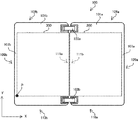
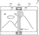
図1は、本実施の形態にかかる折り畳み式電子機器の一例としてのスマートフォン100の平面図である。本発明の適用が可能な折り畳み式の電子機器の他の例としては、ノートブックPC、携帯電話およびタブレットPCなどを挙げることができる。また、本発明の適用は折り畳み式の電子機器に限定するものではなく、本発明は複数のディスプレイを並べて大きなデスクトップ画面を構成する他の表示装置に適用することもできる。図2はスマートフォン100の側面図および断面図で、図3はスマートフォン100の内側面111a、111bの近辺を示す部分的な断面図である。図4は、フレキシブル・ディスプレイ200、300の表示領域を説明する図である。
FIG. 1 is a plan view of a
図1において、スマートフォン100は、ユニット101a、101bがヒンジ機構103a、103bで結合され開閉ができるようになっている。図1は、ユニット101a、101bを開いて使用するときの状態を示しているが、保管時または携帯時はフレキシブル・ディスプレイ200、300が向かい合うように折りたたむことができる(図2(B))。本明細書では、図1の状態をオープン状態といい図2(B)の状態をクローズ状態ということにする。
In FIG. 1, a
スマートフォン100に対して、フレキシブル・ディスプレイ300の左下のコーナーの位置Pを原点にしてX−Y座標を定義する。また、下向きにZ軸を定義する(図3)。ユニット101a、101bは相互に独立した筐体とそれぞれが収納する電子デバイスで構成している。ユニット101a、101bはそれぞれ外形上の輪郭の一部を画定する外側面109a、109b、内側面111a、111b、上側面108a、108bおよび下側面110a、110bを備える。また、外側面109a、109b、上側面108a、108b、下側面110a、110bとフレキシブル・ディスプレイ200、300の3辺の縁との間には縁枠107a、107bを配置している。
For the
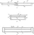
図2(A)は、オープン状態の断面図で、図2(B)はクローズ状態の断面図で、図2(C)はクローズ状態における内側面111a、111bを示す側面図である。ユニット101a、101bの輪郭は、それぞれベース・プレート115a、115bと積層体113a、113bの表面が構成している。図2では省略しているが、ベース・プレート115a、115bと積層体113a、113bが形成する空間は、半導体チップや回路素子を実装した回路基板、電池ユニット、電源回路などの電子デバイスを収納する(図5)。
2A is a cross-sectional view in the open state, FIG. 2B is a cross-sectional view in the closed state, and FIG. 2C is a side view showing the
ベース・プレート115a、115bは、スマートフォン100の構造体として機能し、アルミニウムやマグネシウムなどの金属材料または合成樹脂で形成することができる。ヒンジ機構103a、103bはオープン状態では内側面111a、111bが相互に対向し、クローズ状態では内側面111a、111bが隣接するようにベース・プレート115a、115bを結合する。図2(C)は、内側面111a、111bに設けたフレキシブル・ディスプレイ200、300の副表示領域200g、300g(図4)を示している。副表示領域200g、300gは、内側面111a、111bのいずれか一方にだけ設けてもよい。
The
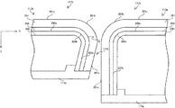
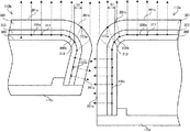
図3に示すように積層体113a、113bは、上からトップ・プレート201、301、タッチ・パネル203、303およびフレキシブル・ディスプレイ200、300を積層した構造になっている。トップ・プレート201、301およびベース・プレート115a、115bは、スマートフォン100の筐体として機能する。トップ・プレート201、301は、アクリル樹脂またはガラスなどの光透過率が高い材料で形成している。トップ・プレート201、301は、上面平坦部201a、301a、湾曲部201b、301b、および側面平坦部201c、301cを含んでいる。
As shown in FIG. 3, the
上面平坦部201a、301aおよび側面平坦部201c、301cは、それぞれ外側の表面が平面上に存在する。本実施形態では上面平坦部201a、301aは、X−Y平面に対してほぼ平行な平面としている。湾曲部201b、301bは、ベース・プレート115a、115bの方向(Z軸方向)に向かって湾曲している。上面平坦部201aと湾曲部201bはフレキシブル・ディスプレイ200の上面117aを構成し、側面平坦部201cと湾曲部201bはフレキシブル・ディスプレイ200の内側面111aを構成する。
The upper surface
また、上面平坦部301aと湾曲部301bはフレキシブル・ディスプレイ300の上面117bを構成し、側面平坦部301cと湾曲部301bはフレキシブル・ディスプレイ300の内側面111bを構成する。オープン状態ではフレキシブル・ディスプレイ200、300の上面117a、117bが隣接し、クローズ状態では上面117a、117bが対向する。湾曲部201b、301bは、後に説明する光屈折効果を発揮して画像の歪みと表示欠損を最小化できるように計算した曲率で形成することができる。
The upper
トップ・プレート201、301の内側にはその表面に沿って、可撓性があって光透過率の高い材料で形成した静電容量式のタッチ・パネル203、303を貼り付けている。タッチ・パネル203、303は、トップ・プレート201、301の表面にタッチ操作をする指の位置をフレキシブル・ディスプレイ200、300の座標として検出して出力する。タッチ・パネル203、303の検出原理は静電容量式に限定する必要はなく、抵抗膜式または光学式などの他の検出原理のタッチ・パネルを採用することができる。
タッチ・パネル203、303の内側にはその表面に沿って、フレキシブル・ディスプレイ200、300を貼り付けている。フレキシブル・ディスプレイ200、300は自発光式の表示装置で、発光素子は特に限定する必要はなく有機EL素子、無機EL素子、電界放出素子、プラズマ放電素子、電気泳動素子などのさまざまな発光素子を採用することができるがここでは有機EL素子を例にして説明する。フレキシブル・ディスプレイ200、300は、電子ペーパという範疇の表示装置であってもよい。
フレキシブル・ディスプレイ200、300は、黒白表示でもカラー表示でもよい。カラー表示の場合は着色光を放射する発光素子を使用してもよいし、白色光を放射する発光素子とカラー・フィルタを組み合わせてもよい。フレキシブル・ディスプレイ200、300の駆動方式はパッシブ・マトリクス方式でもよいが、ここではアクティブ・マトリクス方式を例にして説明する。フレキシブル・ディスプレイ200、300は、トップ・プレート201、301およびタッチ・パネル203、303の形状に沿って積層するためそれらの形状に応じて形状が画定する。フレキシブル・ディスプレイ200、300は、主平坦部200a、300a、湾曲部200b、300b、および副平坦部200c、300cを備えている。
The
トップ・プレート201、301およびタッチ・パネル203、303を透過性のある材料で形成しているため、観察できる領域という意味では、主平坦部200aと湾曲部200bもフレキシブル・ディスプレイ200の上面117aを構成し、副平坦部200cと湾曲部200bもフレキシブル・ディスプレイ200の内側面111aを構成する。同様に、主平坦部300aと湾曲部300bはフレキシブル・ディスプレイ300の上面117bを構成し、副平坦部300cと湾曲部300bはフレキシブル・ディスプレイ300の内側面111bを構成する。オープン状態では副平坦部200c、300cが対向し、クローズ状態では主平坦部200a、300aが対向する。
Since the
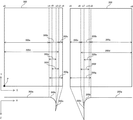
図4は、フレキシブル・ディスプレイ200、300をトップ・プレート201、301に組み込んだ状態の側面と、平坦な面に展開した平面を示している。フレキシブル・ディスプレイ200、300をトップ・プレート201、301に組み込んだときに、主平坦部200a、300aおよび副平坦部200c、300cは平面を維持し、湾曲部200b、300bはX軸方向に進むにしたがってZ軸方向に湾曲する。フレキシブル・ディスプレイ200、300はY軸方向ではZ軸方向に湾曲しないため、トップ・プレート201、301に組み込んだフレキシブル・ディスプレイ200、300の特徴的な形状はX座標で説明することができる。
FIG. 4 shows a side surface in a state in which the
座標x8〜x9、x0〜x1が画定する領域は主平坦部200a、300aに対応し、座標x6〜x8、x1〜x3が画定する領域は湾曲部200b、300bに対応し、座標x5〜x6、x3〜x4が画定する領域は副平坦部200c、300cに対応する。観察者が主平坦部200a、300aを正面にみる方向を主正対視方向といい、主正対視方向から観察することを主正対視ということにする。主平坦部200a、300aおよび湾曲部200b、300bが構成する上面117a、117b(図3)は主正対視で観察できる領域に相当する。
The regions defined by the coordinates x8 to x9 and x0 to x1 correspond to the main
トップ・プレート201、301に組み込んだときに主正対視方向にみえる湾曲部200b、300bの長さx7〜x8、x1〜x2は平面に展開したときの長さ200b、300bに比べて短くなり、さらに副平坦部200c、300cを主正対視することはできない。長さx7〜x8、x1〜x2で画定する湾曲部200b、300bの主正対視方向の長さを有効表示領域200e、300eということにする。主平坦部200a、300aと湾曲部200b、300bを加えた領域を主表示領域200d、300dということにする。
The lengths x7 to x8 and x1 to x2 of the
図2(C)に示すようにクローズ状態において観察者が内側面111a、111bを正面にみる方向を副正対視方向といい、副正対視方向からみることを副正対視ということにする。副平坦部201c、301cおよび湾曲部201b、301bが構成する内側面111a、111bは、副正対視で観察できる領域に相当する。なお、図3では側面平坦部301c、副平坦部300cがデザイン上の目的でわずかに傾斜しているが、傾斜角が小さいのでクローズ状態における副平坦部200cに対する副正対視方向を副平坦部300cに対する副正対視方向とみなすことができる。当然ながら、オープン状態で側面平坦部301c、副平坦部300cと側面平坦部201c、副平坦部200cが平行になるようにトップ・プレート201、301を形成してもよい。
As shown in FIG. 2C, the direction in which the observer views the
トップ・プレート201、301に組み込んだときに副正対視方向からみえる湾曲部200b、300bの長さx6〜x10、x9〜x3は平面に展開したときの長さ200b、300bに比べて短くなる。長さx6〜x10、x9〜x3で画定する湾曲部200b、300bの副正対視方向の長さを有効表示領域200f、300fということにする。副平坦部200c、300cと湾曲部200b、300bを加えた領域を副表示領域200g、300gということにする。副表示領域200g、300gには比較的小さい画像データを表示するため、いずれか一方だけを使用することもできる。また、湾曲部200b、300bを使用しないことでもよい。フレキシブル・ディスプレイ200、300は4辺がシール材で塞がれている。
The lengths x6 to x10 and x9 to x3 of the
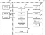
図5は、スマートフォン100が搭載する主要なデバイスの一例を示す機能ブロック図である。一例としてユニット101aは、システム400および電源回路407とシステム400に接続されたGPU401、フレキシブル・ディスプレイ200、タッチ・パネル203、SSD405、通信モジュール407およびカメラ409などを搭載する。ユニット101bは、システム400に接続されたフレキシブル・ディスプレイ300、タッチ・パネル303およびリッド・センサ401を搭載する。なお、ユニット101a、101bに搭載するデバイスの種類は図5の例に限定する必要はなく、たとえば、カメラ409をユニット101bに搭載してもよい。さらに、スマートフォン100は多くのデバイスを含むが、それらは本発明の理解に必要がないため説明を省略する。
FIG. 5 is a functional block diagram illustrating an example of main devices installed in the
SSD403は、オペレーティング・システム、アプリケーション・プログラム、およびデバイス・ドライバなどのソフトウェアを格納する。通信モジュール407は、WiFi(登録商標)、電話、近距離無線通信(NFC)、およびGPSなどの無線通信を行う。リッド・センサ403は、ユニット101a、101bがクローズ状態とそれ以外の状態のいずれかを検出してシステム400に通知する。システム400は、CPU、システム・メモリ、チップセットおよびファームウェアROMなどのハードウェアと、CPUが実行するSSD405に格納したソフトウェアの協働により構成する。ユニット101aが搭載するデバイスとユニット101bが搭載するデバイスとは、ヒンジ機構103a、103bを通じて配線する。
The
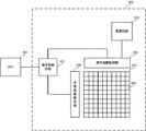
図6は、フレキシブル・ディスプレイ200の概略構成を説明する機能ブロック図である。フレキシブル・ディスプレイ300も同様に構成することができる。画素マトリクス257は、マトリクス状に配置した複数の画素259で構成している。画素マトリクス257は、フレキシブル・ディスプレイ200、300のx0〜x4およびs5〜x9で示す領域の全体に形成する(図4)。
FIG. 6 is a functional block diagram illustrating a schematic configuration of the
画素マトリクス259の周囲にはシール材を設ける。各画素259は信号線駆動回路255とデータ線および電流供給線で接続し、走査線駆動回路256と走査線で接続する。各画素259は、発光層として機能する有機EL素子、画素の選択および有機EL素子に対する供給電流を制御するスイッチ素子(TFT)、および画像データを記憶するキャパシタなどで構成している。
A sealant is provided around the
信号制御回路251は、GPU401からRGBデータ信号、同期信号、およびクロック信号を受け取って、信号線駆動回路255および走査線駆動回路256を駆動する制御信号を生成し、所定のタイミングで信号線駆動回路255にRGBデータ信号を送る。電源回路253は、フレキシブル・ディスプレイ200を構成する回路に電源を供給するとともに、有機EL素子を発光させる電流を信号線駆動回路255に供給する。信号制御回路251、信号線駆動回路255、走査線駆動回路256、および電源回路251などは、図1に示す縁枠107a、107bの下に配置する。
The
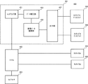
図7はスマートフォン100が実装する表示システム450を説明するための機能ブロック図である。GPU401は、SSD405が格納するデバイス・ドライバを実行して、レンダリング部451、データ補正部453、画像データ展開部455、および出力部457を構成する。レンダリング部451は、システム400から受け取った描画コマンドを処理してフレキシブル・ディスプレイ200、300に表示する画像イメージに直接対応した画像データを生成する。
FIG. 7 is a functional block diagram for explaining the
レンダリング部451は、システム400から主表示領域200d、300dと副表示領域200g、300gのいずれに画像を表示するかを示すコマンドを受け取る。主表示領域200d、300dに表示することを主画面表示といい、副表示領域200g、300gに表示することを副画面表示ということにする。レンダリング部451は主画面表示のときに、フレキシブル・ディスプレイ200の大きさを主平坦部200aと有効表示領域200eの合計の画素数として認識し、フレキシブル・ディスプレイ300の大きさを、主平坦部300aと有効表示領域300eの合計の画素数として認識してそれに適合する画像データを生成する。
The
レンダリング部451は副画面表示のときに、フレキシブル・ディスプレイ200の大きさを副平坦部200cと有効表示領域200fの合計の画素数として認識し、フレキシブル・ディスプレイ300の大きさを、副平坦部300cと有効表示領域300fの合計の画素数として認識してそれに適合する画像データを生成する。レンダリング部451は、拡張モードの表示方法が設定されたときに主画面表示のコマンドを受け取ると、主表示領域200dと主表示領域300dが結合された領域の全体を1つのデスクトップ画面として認識する。
The
このときレンダリング部451は主表示領域200d、300dに跨って一画像を表示する画像データを生成する。主正対視のときは、湾曲部200b、300bの画素マトリクス257が表示する画像は、有効表示領域200e、300eの範囲でしか貢献しない。したがって、レンダリング部451が、フレキシブル・ディスプレイ200、300の大きさを主表示領域200d、300dの大きさと認識して画像データを生成すると、主正対視方向で観察する湾曲部200b、300bの画像は主平坦部200a、200bの画像に比べてX軸方向に縮小する。本実施の形態では、この画像の歪みを解消するために、データ補正部453はレンダリング部451から受け取った有効表示領域200e、300eの画像データを、主正対視方向からみえる画像が主平坦部200a、300aが表示する画像に近付くように補正する。
At this time, the
データ補正部453は、レンダリング部451から受け取った画像データのなかで有効表示領域200e、300eの画像データを湾曲部200b、300bの画素数の画像データとなるように補正する。データ補正部453は、有効表示領域200e、300eの画像データに対して所定のX軸方向の位置で補正用の画素を挿入する。補正用の画素は、挿入箇所においてX軸方向に隣接する画素の画像データと同じ画像データを設定したY軸方向に長い線状の画素パターンとすることができる。主正対視でみえる湾曲部200b、300bの画素は、副平坦部200c、300cに近付くに従ってX軸方向の面積が小さくなる。画素の面積の縮小に応じてデータ補正部453は、画素が主平坦部200a、300aから副平坦部200c、300cに近付くに従って挿入するストライプ状の補正用画素パターンのライン数を増やしていく。
The
同様に副正対視のときは、湾曲部200b、300bの画素マトリクス257が表示する画像は、有効表示領域200f、300fの範囲でしか貢献しない。したがって、湾曲部200b、300bが表示する画像データを生成すると、実際にみえる画像は副平坦部200c、300cが表示する画像に比べて縮小する。データ補正部453は、副正対視方向からみえる画像が副平坦部200c、300cの画像に近付くようにレンダリング部451から受け取った画像データを補正する。補正は、主正対視に対する上述の方法と同様の原理で、画素が主平坦部200a、300aに近付くにしたがって補正用の画素パターンのライン数を増やすようにして行うことができる。
Similarly, in the case of sub-facing, the image displayed by the
画像データ展開部455は、データ補正部453が生成した画像データをフレキシブル・ディスプレイ200、300に表示する画像のイメージとして展開する。画像データ展開部455は、フレキシブル・ディスプレイ200、300の全体の画素数に相当する画像データを展開することができる。画像データ展開部455は、主画面表示のときは、主平坦部200a、300aと湾曲部200b、300bに対応する主表示領域200d、300dに補正した画像データを展開し、副画面表示のときは副平坦部200c、300cと湾曲部200b、300bに対応する副表示領域200g、300gに補正した画像データを展開する。
The image
出力部457は、画像データ展開部455が展開した画像データを所定のタイミングでフレキシブル・ディスプレイ200、300に転送する。出力部457は、主画面表示のときに画像データ展開部455に展開した主表示領域200dの画像データをフレキシブル・ディスプレイ200に転送し、主表示領域300dの画像データをフレキシブル・ディスプレイ300に転送する。出力部457は、副画面表示のときに画像データ展開部455に展開した副表示領域200gの画像データをフレキシブル・ディスプレイ200に転送し、副表示領域300gの画像データをフレキシブル・ディスプレイ300に転送する。
The
出力部457は、主画面表示のときは副平坦部200c、300cの画素に対する画像データを出力せず、副画面表示のときは主平坦部200a、300aの画素に対する画像データを出力しないようにして消費電力の低減を図ることができる。システム400は、タッチ・パネル203、303が画像データを出力する範囲に対応する領域だけが動作するように制御することができる。
The
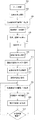
図8は、表示システム450が画像を表示するときの手順を示すフローチャートである。ブロック501で、省電力状態のスマートフォン100をオープン状態にすると、リッド・センサ403が動作して、電源回路407が各デバイスに電力を供給しパワー・オン状態に移行する。GPU401は拡張モードに設定されているものとする。ブロック503でリッド・センサ403からイベントを受け取ったシステム400は、GPU401に主画面表示を行うコマンドを送る。
FIG. 8 is a flowchart showing a procedure when the
ブロック505でレンダリング部451は、主画面表示の画素数に相当する画像データを生成すると、ブロック507でデータ補正部453が湾曲部200b、300bの画像データを補正してから、画像データ展開部455に送る。ブロック509では、フレキシブル・ディスプレイ200、300の主表示領域200d、300dを1つのデスクトップ画面とする画像が表示される。
When the
フレキシブル・ディスプレイ200、300が隣接する位置では、補正された湾曲部200b、300bの画像データも主正対視に対する画像に貢献するため、図10の場合よりも画像の表示欠損の範囲を物理的なギャップG近くまで少なくすることができる。また、湾曲部200b、300bに表示する画像データは補正されているため、主平坦部200a、300aが表示する画像に近い品質の画像を表示することができる。
At the position where the
ブロック511でクローズ状態に移行するとリッド・センサ403が動作してシステム400にイベントを通知する。ブロック513で、システム400は電源部407に指示してスマートフォン100を省電力状態に遷移させる。省電力状態ではフレキシブル・ディスプレイ200、300は動作が停止する。ブロック515でシステム400はタッチ・パネルについて、副表領域200g、300gに対応する領域だけに電力を供給して消費電力の低減を図りながら副表示領域200g、300gに対するタッチ操作の検出を可能にする。
In
システム400は、省電力状態の間に定期的にウェイクして、通信モジュール407を動作させ、新規のメールが到着しているかどうかを調べる。新規のメールが到着している場合は、その情報を不揮発性メモリまたは省電力状態でも電力が供給されて記憶ができる揮発性メモリに書き込んでおく。ブロック517でユーザが副表示領域200g、300gに対してタッチ操作をすると、タッチ・パネル203、303はタッチ・イベントをシステム400に通知する。
The
タッチ・イベントを受け取ったシステム400は、電源回路407に指示してブロック519で副表示領域200g、300gだけに画像を表示するために必要な最小限のデバイスに電力を供給する。ブロック521でシステム400は、不揮発性メモリに記憶して置いたメールの受信を示す画像データを副表示領域200g、300gに表示するためのコマンドをGPU401に送る。なおシステム400はGPU401に、副表示領域200g、300gのいずれか一方にだけ画像を表示するコマンドを送ってもよい。
Receiving the touch event, the
ブロック521でレンダリング部451は、副画面表示の画素数に相当する画像データを生成すると、ブロック523でデータ補正部453が湾曲部200b、300bの画像データを補正してから、画像データ展開部455に送る。ブロック525では、フレキシブル・ディスプレイ200、300の副表示領域200g、300gを1つのデスクトップ画面とする画像が表示される、副表示領域200g、300gが隣接する位置では、補正した湾曲部200b、300bの画像データも副正対視に対する画像に貢献するため、画像の表示欠損の範囲を少なくしかつ表示品質の低下を防ぐことができる。
When the
副表示領域200g、300gにはクローズ状態で、電波の受信状態、現在時刻、天気予報、または電池の充電状態などのさまざまな情報を表示することができる。ただし、副表示領域200g、300gは、表示面積は小さいがフレキシブル・ディスプレイ200、300の一部であるため、システム400から独立してデバイスの状態を表示するインディケータとは異なってシステム400がクローズ状態の間に生成した情報を表示することができる。
In the
図9は、湾曲部201b、301bにおけるトップ・プレート201、301の光屈折効果を説明する図である。図9に示すようにトップ・プレート201、301の厚さはフレキシブル・ディスプレイ200、300の湾曲部200b、300bの相互の間隔を広げるため表示欠損の拡大をもたらす。ガラスまたは透明なアクリル樹脂で製作したトップ・プレート201、301は、屈折率が約1.5で空気の屈折率は1である。従って発光素子が放射した光がトップ・プレート201、301から空気中に出射するときの臨界角は約42度となる。
FIG. 9 is a diagram illustrating the photorefractive effect of the
主平坦部200a、300aにおいてX軸方向に均等な間隔で並んだ画素211、311から出射した光線はトップ・プレート201、301の上面平坦部201a、301aを通過するときは主正対視方向に平行光線として出射する。湾曲部201b、301bの曲率を調整すると、湾曲部200b、300bに均等の間隔で並んだ画素213、313から出射した光線はトップ・カバーの位置213a、313aを通過するときに光屈折効果で屈折して主正対視方向の平行光線として出射させることができる。
When the light beams emitted from the
観察者は、位置213a、313aを対応する画素213、313の発光位置と認識するため、湾曲部200b、300bの画素が相手側のディスプレイに距離S1、S2だけ近付いた位置に存在するように認識する。湾曲部201b、301bの曲率を調整することで表示欠損の面積を縮小させると同時に、主正対視に対する画像の歪みを軽減することができる。光屈折効果は、データ補正部453によるデータ補正に代えてまたはデータ補正と併用して採用することができる。
Since the observer recognizes the
これまで、2つのユニットがヒンジ構造で結合されたディスプレイを例にして説明してきたが、本発明は3つ以上のユニットがヒンジ構造で結合されるディスプレイに対して適用することもできる。この場合、フレキシブル・ディスプレイの制御回路は、側面で180度折り曲げた底面の位置に配置することができる。また、本発明はヒンジ結合されたディスプレイだけでなく、隣接して配置された複数のディスプレイで大きな1つのディスプレイを構成する場合にも適用することができる。 So far, a display in which two units are coupled with a hinge structure has been described as an example. However, the present invention can also be applied to a display in which three or more units are coupled with a hinge structure. In this case, the control circuit of the flexible display can be arranged at the position of the bottom surface bent 180 degrees on the side surface. Further, the present invention can be applied not only to a hinge-coupled display but also to a case where a large single display is configured by a plurality of adjacently arranged displays.
これまで本発明について図面に示した特定の実施の形態をもって説明してきたが、本発明は図面に示した実施の形態に限定されるものではなく、本発明の効果を奏する限り、これまで知られたいかなる構成であっても採用することができることはいうまでもないことである。 Although the present invention has been described with the specific embodiments shown in the drawings, the present invention is not limited to the embodiments shown in the drawings, and is known so far as long as the effects of the present invention are achieved. It goes without saying that any configuration can be adopted.
100 スマートフォン
101a、101b ユニット
103a、103b ヒンジ機構
107a、107b 縁枠
111a、111b 内側面
113a、113b 積層体
115a、115b ベース・プレート
117a、117b 上面
200、300 フレキシブル・ディスプレイ
200a、300a 主平坦部
200b、300b 湾曲部
200c、300c 副平坦部
201、301 トップ・プレート
201a、301a 上面平坦部
201b、301b 湾曲部
201c、301c 側面平坦部
200d、300d 主表示領域
200e、300e 主表示領域に対する有効表示領域
200f、300f 副表示領域に対する有効表示領域
200g、300g 副表示領域
203、303 タッチ・パネル
211、213、259、311、313 画素
257 画素マトリクス
400 システム
450 表示システム
100
Claims (21)
第1の主平坦部と第1の内側面を構成するように湾曲している第1の湾曲部に形成した第1の画素マトリクスを備える第1のフレキシブル・ディスプレイと、
第2の主平坦部と第2の内側面を構成するように湾曲している第2の湾曲部に形成した第2の画素マトリクスを備える第2のフレキシブル・ディスプレイと、
前記第1の画素マトリクスと前記第2の画素マトリクスの表示領域をデスクトップ画面とする画像データを生成する画像データ生成部と
を有する表示システム。 A display system that uses a plurality of displays in an open state or a closed state,
A first flexible display comprising a first pixel matrix formed on a first curved portion that is curved to form a first main flat portion and a first inner surface;
A second flexible display comprising a second pixel matrix formed in a second curved portion curved to form a second main flat portion and a second inner surface;
A display system comprising: an image data generation unit configured to generate image data having a display area of the first pixel matrix and the second pixel matrix as a desktop screen.
上面平坦部と前記内側面を構成するように湾曲する湾曲部と側面平坦部とを有し光透過率の高い材料で形成したトップ・プレートと、
前記トップ・プレートの下に沿って配置し、前記上面平坦部と前記湾曲部に対応する領域に画素マトリクスを備えるフレキシブル・ディスプレイと
を備える表示装置。 A display device that displays a desktop screen that is arranged so as to face another display device on the inner surface and is integrated with the other display device,
A top plate formed of a material having a high light transmittance and having a curved portion and a side flat portion that are curved so as to constitute the upper surface flat portion and the inner surface;
A display device, comprising: a flexible display that is disposed along the top plate and includes a pixel matrix in a region corresponding to the upper flat portion and the curved portion.
第1の上面と第1の内側面を備える第1のトップ・プレートと、
第2の上面とオープン状態で前記第1の内側面に対向しクローズ状態で前記第1の内側面と隣接する第2の内側面を備える第2のトップ・プレートと、
前記第1の上面に配置した第1の主平坦部および第1の湾曲部と、前記第1の内側面に配置した前記第1の湾曲部および第1の副平坦部を備える第1のフレキシブル・ディスプレイと、
前記第2の上面に配置した第2の主平坦部および第2の湾曲部と、前記第1の内側面に配置した前記第2の湾曲部および第2の副平坦部を備える第2のフレキシブル・ディスプレイと、
前記第1のディスプレイと前記第2のディスプレイに表示する画像データを生成する画像データ生成部と、
前記電子機器の動作を制御するシステム制御部と
を有する電子機器。 A foldable electronic device,
A first top plate comprising a first upper surface and a first inner surface;
A second top plate comprising a second inner surface facing the first inner surface in the open state with the second upper surface and adjacent to the first inner surface in the closed state;
A first flexible portion including a first main flat portion and a first curved portion disposed on the first upper surface, and the first curved portion and the first sub-flat portion disposed on the first inner surface.・ Display and
A second flexible portion comprising a second main flat portion and a second curved portion disposed on the second upper surface, and the second curved portion and a second sub-flat portion disposed on the first inner surface.・ Display and
An image data generation unit for generating image data to be displayed on the first display and the second display;
And an electronic device having a system control unit for controlling the operation of the electronic device.
主正対視方向で第1の主平坦部と第1の内側面を構成するように湾曲した第1の湾曲部とが放射した光線を観察することができる第1のフレキシブル・ディスプレイと、
前記主正対視方向で第2の主平坦部と第2の内側面を構成するように湾曲した第2の湾曲部とが放射した光線を観察することができる第2のフレキシブル・ディスプレイと、
前記第1のフレキシブル・ディスプレイと前記第2のフレキシブル・ディスプレイをオープン状態で前記第1の主平坦部と前記第2の主平坦部が隣接しクローズ状態で前記第1の内側面と前記第2の内側面が隣接するように位置付けるヒンジ機構と
を有する電子機器。 A foldable electronic device,
A first flexible display capable of observing light rays emitted by the first main flat portion and the first curved portion curved so as to constitute the first inner surface in the main facing direction;
A second flexible display capable of observing light rays emitted by the second main flat portion and the second curved portion curved so as to constitute the second inner surface in the main facing direction;
When the first flexible display and the second flexible display are in an open state, the first main flat portion and the second main flat portion are adjacent to each other, and the first inner surface and the second are in a closed state. An electronic device having a hinge mechanism positioned so that the inner side surfaces of the two are adjacent to each other.
オープン状態で前記第1のフレキシブル・ディスプレイと前記第2のフレキシブル・ディスプレイの前記上面に配置した主平坦部と、前記内側面に向かって湾曲している湾曲部とにそれぞれ主画面表示をするステップと、
クローズ状態で前記第1のフレキシブル・ディスプレイおよび前記第2のフレキシブル・ディスプレイまたはいずれか一方の前記湾曲部から延びている副平坦部に副画面表示をするステップと
を有する方法。 A first flexible display having a first housing and a second housing coupled by a hinge and extending along an inner surface from an upper surface of the first housing and an upper surface of the second housing A method for displaying an image on an electronic device including a second flexible display extending along an inner surface from
A step of displaying a main screen on a main flat portion disposed on the upper surface of the first flexible display and the second flexible display and a curved portion curved toward the inner surface in the open state. When,
A sub-screen display on a sub-flat portion extending from the curved portion of the first flexible display and / or the second flexible display in a closed state.
前記クローズ状態で前記第1のフレキシブル・ディスプレイおよび前記第2のフレキシブル・ディスプレイまたはいずれか一方に対するタッチ操作を検出するステップと、
前記タッチ操作に応答して前記副画面表示をするステップと
を有する請求項18または請求項19に記載の方法。 Stopping the sub-screen display in the closed state;
Detecting a touch operation on the first flexible display and / or the second flexible display in the closed state;
The method according to claim 18, further comprising: displaying the sub-screen in response to the touch operation.
21. The method according to claim 18, further comprising the step of stopping the sub-screen display in the open state.
Priority Applications (2)
| Application Number | Priority Date | Filing Date | Title |
|---|---|---|---|
| JP2013253703A JP5922639B2 (en) | 2013-12-07 | 2013-12-07 | Foldable electronic device, display system, and display method |
| US14/562,562 US9606763B2 (en) | 2013-12-07 | 2014-12-05 | Folding electronic device |
Applications Claiming Priority (1)
| Application Number | Priority Date | Filing Date | Title |
|---|---|---|---|
| JP2013253703A JP5922639B2 (en) | 2013-12-07 | 2013-12-07 | Foldable electronic device, display system, and display method |
Publications (2)
| Publication Number | Publication Date |
|---|---|
| JP2015114673A true JP2015114673A (en) | 2015-06-22 |
| JP5922639B2 JP5922639B2 (en) | 2016-05-24 |
Family
ID=53271116
Family Applications (1)
| Application Number | Title | Priority Date | Filing Date |
|---|---|---|---|
| JP2013253703A Active JP5922639B2 (en) | 2013-12-07 | 2013-12-07 | Foldable electronic device, display system, and display method |
Country Status (2)
| Country | Link |
|---|---|
| US (1) | US9606763B2 (en) |
| JP (1) | JP5922639B2 (en) |
Cited By (3)
| Publication number | Priority date | Publication date | Assignee | Title |
|---|---|---|---|---|
| KR20180001015A (en) * | 2016-06-24 | 2018-01-04 | 삼성전자주식회사 | Electronic device including a plurality of display |
| KR20180100012A (en) * | 2017-02-28 | 2018-09-06 | 삼성디스플레이 주식회사 | Bending display panel and bending display device having the same |
| US11133574B2 (en) | 2018-10-16 | 2021-09-28 | Murata Manufacturing Co., Ltd. | Communication device |
Families Citing this family (52)
| Publication number | Priority date | Publication date | Assignee | Title |
|---|---|---|---|---|
| US6319670B1 (en) | 1995-05-09 | 2001-11-20 | Meso Scale Technology Llp | Methods and apparatus for improved luminescence assays using microparticles |
| USD819628S1 (en) * | 2014-02-22 | 2018-06-05 | Samsung Electronics Co., Ltd. | Electronic device |
| USD828319S1 (en) * | 2016-02-19 | 2018-09-11 | Lg Electronics Inc. | Mobile phone |
| USD826889S1 (en) * | 2016-02-19 | 2018-08-28 | Lg Electronics Inc. | Mobile phone |
| USD828318S1 (en) * | 2016-02-19 | 2018-09-11 | Lg Electronics Inc. | Mobile phone |
| USD825513S1 (en) * | 2016-02-19 | 2018-08-14 | Lg Electronics Inc. | Mobile phone |
| USD827604S1 (en) * | 2016-02-19 | 2018-09-04 | Lg Electronics Inc. | Mobile phone |
| USD826203S1 (en) * | 2016-02-19 | 2018-08-21 | Lg Electronics Inc. | Mobile phone |
| BR112018017336A2 (en) | 2016-03-07 | 2018-12-26 | Hoffmann La Roche | in vitro method for detecting a p53 antibody (anti-p53 antibody) in a sample and fusion polypeptide |
| USD807855S1 (en) * | 2016-04-01 | 2018-01-16 | Lg Electronics Inc. | Mobile phone |
| USD807854S1 (en) * | 2016-04-01 | 2018-01-16 | Lg Electronics Inc. | Mobile phone |
| USD815055S1 (en) * | 2016-04-01 | 2018-04-10 | Lg Electronics Inc. | Mobile phone |
| USD807856S1 (en) * | 2016-04-01 | 2018-01-16 | Lg Electronics Inc. | Mobile phone |
| USD842833S1 (en) * | 2017-01-10 | 2019-03-12 | Lg Electronics Inc. | Mobile phone |
| CN106936982A (en) * | 2017-01-14 | 2017-07-07 | 惠州Tcl移动通信有限公司 | Terminal and its display methods with flexible display screen |
| JP7068323B2 (en) | 2017-02-02 | 2022-05-16 | エフ.ホフマン-ラ ロシュ アーゲー | Immunoassay using at least two pegged analyte-specific binders |
| CN107766022A (en) * | 2017-10-19 | 2018-03-06 | 广东欧珀移动通信有限公司 | A screen display method, device and storage medium |
| CN111386698B (en) * | 2017-12-06 | 2023-04-07 | 索尼公司 | display device |
| EP3781600A1 (en) | 2018-04-18 | 2021-02-24 | F. Hoffmann-La Roche AG | Novel anti-thymidine kinase antibodies |
| JP7577647B2 (en) | 2018-08-31 | 2024-11-05 | エフ. ホフマン-ラ ロシュ アーゲー | Thymidine kinase (TK-1) in prognostic indicators for DLBCL |
| US11272045B2 (en) * | 2018-11-05 | 2022-03-08 | Microsoft Technology Licensing, Llc | Display presentation across plural display surfaces |
| CN110213413B (en) * | 2019-05-31 | 2021-05-14 | Oppo广东移动通信有限公司 | Control method of electronic device and electronic device |
| EP4004555A1 (en) | 2019-07-22 | 2022-06-01 | F. Hoffmann-La Roche AG | S100a6 as blood biomarker for the non-invasive diagnosis of endometriosis |
| EP4004551A1 (en) | 2019-07-22 | 2022-06-01 | F. Hoffmann-La Roche AG | Substance p as blood biomarker for the non-invasive diagnosis of endometriosis |
| WO2021013785A1 (en) | 2019-07-22 | 2021-01-28 | F. Hoffmann-La Roche Ag | S100a9 as blood biomarker for the non-invasive diagnosis of endometriosis |
| WO2021013783A1 (en) | 2019-07-22 | 2021-01-28 | F. Hoffmann-La Roche Ag | S100a12 as blood biomarker for the non-invasive diagnosis of endometriosis |
| EP4004553A1 (en) | 2019-07-22 | 2022-06-01 | F. Hoffmann-La Roche AG | S100a8 as blood biomarker for the non-invasive diagnosis of endometriosis |
| KR102574288B1 (en) * | 2019-08-07 | 2023-09-07 | 삼성전자주식회사 | Method and bendable device for constructing 3D data items |
| USD976900S1 (en) * | 2019-10-01 | 2023-01-31 | Microsoft Corporation | Computing device |
| USD976896S1 (en) | 2019-10-01 | 2023-01-31 | Microsoft Corporation | Computing device |
| USD982579S1 (en) | 2019-10-01 | 2023-04-04 | Microsoft Corporation | Computing device |
| USD962938S1 (en) | 2019-10-01 | 2022-09-06 | Microsoft Corporation | Computing device |
| USD984997S1 (en) | 2019-10-01 | 2023-05-02 | Microsoft Corporation | Keyboard |
| USD980838S1 (en) * | 2019-10-01 | 2023-03-14 | Microsoft Corporation | Computing device |
| KR20220100883A (en) | 2019-11-15 | 2022-07-18 | 에프. 호프만-라 로슈 아게 | Derivatization of Beta-Lactam Antibiotics for Mass Spectrometry Determination of Patient Samples |
| USD978140S1 (en) * | 2020-04-27 | 2023-02-14 | Samsung Electronics Co., Ltd. | Electronic device |
| JP7851928B2 (en) | 2020-11-02 | 2026-04-27 | エフ. ホフマン-ラ ロシュ アーゲー | SARS-CoV-2 nucleocapsid antibody |
| WO2022207628A1 (en) | 2021-03-30 | 2022-10-06 | F. Hoffmann-La Roche Ag | Scf as blood biomarker for the non-invasive diagnosis of endometriosis |
| WO2022207685A1 (en) | 2021-04-01 | 2022-10-06 | F. Hoffmann-La Roche Ag | Psp94 as blood biomarker for the non-invasive diagnosis of endometriosis |
| CN117337394A (en) | 2021-05-17 | 2024-01-02 | 豪夫迈·罗氏有限公司 | sFRP4 as a blood biomarker for non-invasive diagnosis of adenomyosis |
| WO2023072904A1 (en) | 2021-10-26 | 2023-05-04 | F. Hoffmann-La Roche Ag | Monoclonal antibodies specific for sars-cov-2 rbd |
| US20230186871A1 (en) * | 2021-12-10 | 2023-06-15 | Microsoft Technology Licensing, Llc | Visual content rendering for electronic display system |
| WO2023131594A1 (en) | 2022-01-05 | 2023-07-13 | F. Hoffmann-La Roche Ag | Derivatization of compounds in patient samples for therapeutic drug monitoring (tdm) |
| WO2023153896A1 (en) * | 2022-02-14 | 2023-08-17 | 삼성전자 주식회사 | Multi-display structure and electronic device comprising same |
| EP4468110A4 (en) | 2022-02-14 | 2025-04-23 | Samsung Electronics Co., Ltd. | MULTI-DISPLAY STRUCTURE AND ELECTRONIC DEVICE THEREOF |
| JP2025520600A (en) | 2022-06-23 | 2025-07-03 | エフ. ホフマン-ラ ロシュ アーゲー | Methods for diagnosing and staging endometriosis - Patents.com |
| EP4558830A1 (en) | 2022-07-22 | 2025-05-28 | F. Hoffmann-La Roche AG | Leukotriene a4 hydrolase (lta4h) as (blood) biomarker for the diagnosis of polycystic ovarian syndrome |
| EP4558826A1 (en) | 2022-07-22 | 2025-05-28 | F. Hoffmann-La Roche AG | Fibroblast growth factor binding protein 1 (fgfbp1) as (blood) biomarker for the diagnosis of polycystic ovarian syndrome |
| JP2025524027A (en) | 2022-07-22 | 2025-07-25 | エフ. ホフマン-ラ ロシュ アーゲー | Meteorin-like protein (METRNL) as a (blood) biomarker for the diagnosis of polycystic ovary syndrome |
| CN121532654A (en) | 2023-07-20 | 2026-02-13 | 豪夫迈·罗氏有限公司 | Screening methods for antibody compositions |
| CN121752901A (en) | 2023-07-28 | 2026-03-27 | 豪夫迈·罗氏有限公司 | Serum EphA1 as a biomarker of endometriosis |
| CN118072614B (en) * | 2024-01-16 | 2025-03-18 | 荣耀终端股份有限公司 | Folding screen device, opening and closing detection device and opening and closing state detection method |
Citations (3)
| Publication number | Priority date | Publication date | Assignee | Title |
|---|---|---|---|---|
| JP2012073293A (en) * | 2010-09-27 | 2012-04-12 | Nec Personal Computers Ltd | Display device |
| US20120206896A1 (en) * | 2011-02-15 | 2012-08-16 | Kabushiki Kaisha Toshiba | Electronic apparatus |
| JP2013164498A (en) * | 2012-02-10 | 2013-08-22 | Sony Corp | Display device |
Family Cites Families (1)
| Publication number | Priority date | Publication date | Assignee | Title |
|---|---|---|---|---|
| US8804317B2 (en) * | 2009-07-01 | 2014-08-12 | Sharp Kabushiki Kaisha | Display device |
-
2013
- 2013-12-07 JP JP2013253703A patent/JP5922639B2/en active Active
-
2014
- 2014-12-05 US US14/562,562 patent/US9606763B2/en active Active
Patent Citations (3)
| Publication number | Priority date | Publication date | Assignee | Title |
|---|---|---|---|---|
| JP2012073293A (en) * | 2010-09-27 | 2012-04-12 | Nec Personal Computers Ltd | Display device |
| US20120206896A1 (en) * | 2011-02-15 | 2012-08-16 | Kabushiki Kaisha Toshiba | Electronic apparatus |
| JP2013164498A (en) * | 2012-02-10 | 2013-08-22 | Sony Corp | Display device |
Cited By (5)
| Publication number | Priority date | Publication date | Assignee | Title |
|---|---|---|---|---|
| KR20180001015A (en) * | 2016-06-24 | 2018-01-04 | 삼성전자주식회사 | Electronic device including a plurality of display |
| KR102520552B1 (en) * | 2016-06-24 | 2023-04-12 | 삼성전자주식회사 | Electronic device including a plurality of display |
| KR20180100012A (en) * | 2017-02-28 | 2018-09-06 | 삼성디스플레이 주식회사 | Bending display panel and bending display device having the same |
| KR102715870B1 (en) * | 2017-02-28 | 2024-10-14 | 삼성디스플레이 주식회사 | Bending display panel and bending display device having the same |
| US11133574B2 (en) | 2018-10-16 | 2021-09-28 | Murata Manufacturing Co., Ltd. | Communication device |
Also Published As
| Publication number | Publication date |
|---|---|
| US9606763B2 (en) | 2017-03-28 |
| JP5922639B2 (en) | 2016-05-24 |
| US20150160698A1 (en) | 2015-06-11 |
Similar Documents
| Publication | Publication Date | Title |
|---|---|---|
| JP5922639B2 (en) | Foldable electronic device, display system, and display method | |
| EP3428967B1 (en) | Electronic device having display | |
| US10620768B2 (en) | Flexible display panel, manufacturing method thereof and display device | |
| KR20250021356A (en) | Display device | |
| KR102578589B1 (en) | Flexible display | |
| US20260090227A1 (en) | Electronic device with display portion | |
| US11714455B2 (en) | Flexible display panel, display device, and method for controlling display of display device | |
| KR102281910B1 (en) | Display module and display apparatus having the same | |
| US8269754B2 (en) | Portable terminal, display control program, and display control method | |
| EP4246503A2 (en) | Electronic device having display | |
| US20230079023A1 (en) | Display device and electronic apparatus including the same | |
| CN109727540B (en) | Foldable display device | |
| CN106057087A (en) | Display module | |
| KR102662389B1 (en) | Display device | |
| KR102671313B1 (en) | Display and electronic device including thereof | |
| CN102855821A (en) | Flexible display panel and display apparatus including the flexible display panel | |
| KR102903580B1 (en) | Display device | |
| US20180210267A1 (en) | Display module and method for fitting the same | |
| CN108255357A (en) | Touch display unit and its driving method | |
| US20200110214A1 (en) | Backlight unit and display device including the same | |
| CN111613133A (en) | display device | |
| KR102794228B1 (en) | Display device | |
| KR102601644B1 (en) | Display device and driving method using the same | |
| KR102773739B1 (en) | Flexible Display Device | |
| KR102695746B1 (en) | An electronic device including a display and an enhancing method of a distortion of an image displayed by the electronic device |
Legal Events
| Date | Code | Title | Description |
|---|---|---|---|
| RD02 | Notification of acceptance of power of attorney |
Free format text: JAPANESE INTERMEDIATE CODE: A7422 Effective date: 20150330 |
|
| RD14 | Notification of resignation of power of sub attorney |
Free format text: JAPANESE INTERMEDIATE CODE: A7434 Effective date: 20150410 |
|
| RD14 | Notification of resignation of power of sub attorney |
Free format text: JAPANESE INTERMEDIATE CODE: A7434 Effective date: 20150416 |
|
| A977 | Report on retrieval |
Free format text: JAPANESE INTERMEDIATE CODE: A971007 Effective date: 20151015 |
|
| A131 | Notification of reasons for refusal |
Free format text: JAPANESE INTERMEDIATE CODE: A131 Effective date: 20151208 |
|
| A521 | Request for written amendment filed |
Free format text: JAPANESE INTERMEDIATE CODE: A523 Effective date: 20160220 |
|
| TRDD | Decision of grant or rejection written | ||
| A01 | Written decision to grant a patent or to grant a registration (utility model) |
Free format text: JAPANESE INTERMEDIATE CODE: A01 Effective date: 20160412 |
|
| A61 | First payment of annual fees (during grant procedure) |
Free format text: JAPANESE INTERMEDIATE CODE: A61 Effective date: 20160414 |
|
| R150 | Certificate of patent or registration of utility model |
Ref document number: 5922639 Country of ref document: JP Free format text: JAPANESE INTERMEDIATE CODE: R150 |
|
| R250 | Receipt of annual fees |
Free format text: JAPANESE INTERMEDIATE CODE: R250 |
|
| S111 | Request for change of ownership or part of ownership |
Free format text: JAPANESE INTERMEDIATE CODE: R313113 |
|
| R360 | Written notification for declining of transfer of rights |
Free format text: JAPANESE INTERMEDIATE CODE: R360 |
|
| R360 | Written notification for declining of transfer of rights |
Free format text: JAPANESE INTERMEDIATE CODE: R360 |
|
| R371 | Transfer withdrawn |
Free format text: JAPANESE INTERMEDIATE CODE: R371 |
|
| S111 | Request for change of ownership or part of ownership |
Free format text: JAPANESE INTERMEDIATE CODE: R313113 |
|
| R350 | Written notification of registration of transfer |
Free format text: JAPANESE INTERMEDIATE CODE: R350 |
|
| R250 | Receipt of annual fees |
Free format text: JAPANESE INTERMEDIATE CODE: R250 |
|
| R250 | Receipt of annual fees |
Free format text: JAPANESE INTERMEDIATE CODE: R250 |
|
| R250 | Receipt of annual fees |
Free format text: JAPANESE INTERMEDIATE CODE: R250 |
|
| R250 | Receipt of annual fees |
Free format text: JAPANESE INTERMEDIATE CODE: R250 |
|
| R250 | Receipt of annual fees |
Free format text: JAPANESE INTERMEDIATE CODE: R250 |
|
| S111 | Request for change of ownership or part of ownership |
Free format text: JAPANESE INTERMEDIATE CODE: R313113 |
|
| R250 | Receipt of annual fees |
Free format text: JAPANESE INTERMEDIATE CODE: R250 |
|
| R350 | Written notification of registration of transfer |
Free format text: JAPANESE INTERMEDIATE CODE: R350 |
|
| R250 | Receipt of annual fees |
Free format text: JAPANESE INTERMEDIATE CODE: R250 |