JP2015114647A - Image forming apparatus and image forming method - Google Patents
Image forming apparatus and image forming method Download PDFInfo
- Publication number
- JP2015114647A JP2015114647A JP2013259026A JP2013259026A JP2015114647A JP 2015114647 A JP2015114647 A JP 2015114647A JP 2013259026 A JP2013259026 A JP 2013259026A JP 2013259026 A JP2013259026 A JP 2013259026A JP 2015114647 A JP2015114647 A JP 2015114647A
- Authority
- JP
- Japan
- Prior art keywords
- lubricant
- photoreceptor
- image forming
- photoconductor
- toner
- Prior art date
- Legal status (The legal status is an assumption and is not a legal conclusion. Google has not performed a legal analysis and makes no representation as to the accuracy of the status listed.)
- Granted
Links
- 238000000034 method Methods 0.000 title claims abstract description 80
- 239000000314 lubricant Substances 0.000 claims abstract description 224
- 108091008695 photoreceptors Proteins 0.000 claims abstract description 107
- 238000004140 cleaning Methods 0.000 claims abstract description 73
- 238000012546 transfer Methods 0.000 claims abstract description 69
- 150000001875 compounds Chemical class 0.000 claims abstract description 36
- 229920006037 cross link polymer Polymers 0.000 claims abstract description 12
- 238000011144 upstream manufacturing Methods 0.000 claims abstract description 8
- 239000011241 protective layer Substances 0.000 claims description 46
- 230000008569 process Effects 0.000 claims description 24
- XOOUIPVCVHRTMJ-UHFFFAOYSA-L zinc stearate Chemical compound [Zn+2].CCCCCCCCCCCCCCCCCC([O-])=O.CCCCCCCCCCCCCCCCCC([O-])=O XOOUIPVCVHRTMJ-UHFFFAOYSA-L 0.000 claims description 9
- 230000009471 action Effects 0.000 claims description 7
- 239000007787 solid Substances 0.000 claims description 6
- 239000000843 powder Substances 0.000 claims description 5
- 230000005684 electric field Effects 0.000 claims description 4
- 238000012217 deletion Methods 0.000 abstract 1
- 230000037430 deletion Effects 0.000 abstract 1
- 239000010410 layer Substances 0.000 description 33
- 238000000576 coating method Methods 0.000 description 30
- 239000011248 coating agent Substances 0.000 description 25
- 239000010419 fine particle Substances 0.000 description 24
- 229910052751 metal Inorganic materials 0.000 description 24
- 239000002184 metal Substances 0.000 description 24
- 229910044991 metal oxide Inorganic materials 0.000 description 24
- 150000004706 metal oxides Chemical class 0.000 description 24
- 239000000463 material Substances 0.000 description 21
- 239000002245 particle Substances 0.000 description 21
- 229920005989 resin Polymers 0.000 description 21
- 239000011347 resin Substances 0.000 description 21
- 125000004429 atom Chemical group 0.000 description 20
- 238000011156 evaluation Methods 0.000 description 18
- 239000000835 fiber Substances 0.000 description 18
- OKKJLVBELUTLKV-UHFFFAOYSA-N Methanol Chemical compound OC OKKJLVBELUTLKV-UHFFFAOYSA-N 0.000 description 15
- VYPSYNLAJGMNEJ-UHFFFAOYSA-N Silicium dioxide Chemical compound O=[Si]=O VYPSYNLAJGMNEJ-UHFFFAOYSA-N 0.000 description 14
- 230000015572 biosynthetic process Effects 0.000 description 14
- 239000002904 solvent Substances 0.000 description 13
- SJHHDDDGXWOYOE-UHFFFAOYSA-N oxytitamium phthalocyanine Chemical compound [Ti+2]=O.C12=CC=CC=C2C(N=C2[N-]C(C3=CC=CC=C32)=N2)=NC1=NC([C]1C=CC=CC1=1)=NC=1N=C1[C]3C=CC=CC3=C2[N-]1 SJHHDDDGXWOYOE-UHFFFAOYSA-N 0.000 description 11
- 239000000243 solution Substances 0.000 description 11
- 238000001035 drying Methods 0.000 description 10
- -1 methacryloyl groups Chemical group 0.000 description 10
- 238000010894 electron beam technology Methods 0.000 description 9
- 239000003999 initiator Substances 0.000 description 9
- 239000000178 monomer Substances 0.000 description 9
- 238000002360 preparation method Methods 0.000 description 9
- YXFVVABEGXRONW-UHFFFAOYSA-N Toluene Chemical compound CC1=CC=CC=C1 YXFVVABEGXRONW-UHFFFAOYSA-N 0.000 description 8
- 239000003505 polymerization initiator Substances 0.000 description 8
- 239000012756 surface treatment agent Substances 0.000 description 8
- 238000005259 measurement Methods 0.000 description 7
- 239000000203 mixture Substances 0.000 description 7
- 230000002093 peripheral effect Effects 0.000 description 7
- GWEVSGVZZGPLCZ-UHFFFAOYSA-N Titan oxide Chemical compound O=[Ti]=O GWEVSGVZZGPLCZ-UHFFFAOYSA-N 0.000 description 6
- 230000000052 comparative effect Effects 0.000 description 6
- 239000011164 primary particle Substances 0.000 description 6
- 150000003254 radicals Chemical class 0.000 description 6
- XOLBLPGZBRYERU-UHFFFAOYSA-N tin dioxide Chemical compound O=[Sn]=O XOLBLPGZBRYERU-UHFFFAOYSA-N 0.000 description 6
- 229910001887 tin oxide Inorganic materials 0.000 description 6
- KFZMGEQAYNKOFK-UHFFFAOYSA-N Isopropanol Chemical compound CC(C)O KFZMGEQAYNKOFK-UHFFFAOYSA-N 0.000 description 5
- 229910052799 carbon Inorganic materials 0.000 description 5
- 239000003795 chemical substances by application Substances 0.000 description 5
- 239000000049 pigment Substances 0.000 description 5
- 238000007639 printing Methods 0.000 description 5
- OWBTYPJTUOEWEK-UHFFFAOYSA-N (-)-(2R,3R)--2,3-butanediol Natural products CC(O)C(C)O OWBTYPJTUOEWEK-UHFFFAOYSA-N 0.000 description 4
- OWBTYPJTUOEWEK-QWWZWVQMSA-N (R,R)-butane-2,3-diol Chemical compound C[C@@H](O)[C@@H](C)O OWBTYPJTUOEWEK-QWWZWVQMSA-N 0.000 description 4
- IJGRMHOSHXDMSA-UHFFFAOYSA-N Atomic nitrogen Chemical compound N#N IJGRMHOSHXDMSA-UHFFFAOYSA-N 0.000 description 4
- OKTJSMMVPCPJKN-UHFFFAOYSA-N Carbon Chemical compound [C] OKTJSMMVPCPJKN-UHFFFAOYSA-N 0.000 description 4
- WYURNTSHIVDZCO-UHFFFAOYSA-N Tetrahydrofuran Chemical compound C1CCOC1 WYURNTSHIVDZCO-UHFFFAOYSA-N 0.000 description 4
- 125000003647 acryloyl group Chemical group O=C([*])C([H])=C([H])[H] 0.000 description 4
- 239000011230 binding agent Substances 0.000 description 4
- BTANRVKWQNVYAZ-UHFFFAOYSA-N butan-2-ol Chemical compound CCC(C)O BTANRVKWQNVYAZ-UHFFFAOYSA-N 0.000 description 4
- 238000006243 chemical reaction Methods 0.000 description 4
- 239000013078 crystal Substances 0.000 description 4
- 235000014113 dietary fatty acids Nutrition 0.000 description 4
- 239000000194 fatty acid Substances 0.000 description 4
- 229930195729 fatty acid Natural products 0.000 description 4
- 150000004665 fatty acids Chemical class 0.000 description 4
- 125000000524 functional group Chemical group 0.000 description 4
- QSHDDOUJBYECFT-UHFFFAOYSA-N mercury Chemical compound [Hg] QSHDDOUJBYECFT-UHFFFAOYSA-N 0.000 description 4
- 229910052753 mercury Inorganic materials 0.000 description 4
- 150000003839 salts Chemical class 0.000 description 4
- 239000004576 sand Substances 0.000 description 4
- 239000000377 silicon dioxide Substances 0.000 description 4
- RFFLAFLAYFXFSW-UHFFFAOYSA-N 1,2-dichlorobenzene Chemical compound ClC1=CC=CC=C1Cl RFFLAFLAYFXFSW-UHFFFAOYSA-N 0.000 description 3
- ZWEHNKRNPOVVGH-UHFFFAOYSA-N 2-Butanone Chemical compound CCC(C)=O ZWEHNKRNPOVVGH-UHFFFAOYSA-N 0.000 description 3
- YMWUJEATGCHHMB-UHFFFAOYSA-N Dichloromethane Chemical compound ClCCl YMWUJEATGCHHMB-UHFFFAOYSA-N 0.000 description 3
- LFQSCWFLJHTTHZ-UHFFFAOYSA-N Ethanol Chemical compound CCO LFQSCWFLJHTTHZ-UHFFFAOYSA-N 0.000 description 3
- XEKOWRVHYACXOJ-UHFFFAOYSA-N Ethyl acetate Chemical compound CCOC(C)=O XEKOWRVHYACXOJ-UHFFFAOYSA-N 0.000 description 3
- NIXOWILDQLNWCW-UHFFFAOYSA-N acrylic acid group Chemical group C(C=C)(=O)O NIXOWILDQLNWCW-UHFFFAOYSA-N 0.000 description 3
- 238000004220 aggregation Methods 0.000 description 3
- 229910052782 aluminium Inorganic materials 0.000 description 3
- 239000003086 colorant Substances 0.000 description 3
- 238000004132 cross linking Methods 0.000 description 3
- 230000006866 deterioration Effects 0.000 description 3
- 238000003618 dip coating Methods 0.000 description 3
- 230000005294 ferromagnetic effect Effects 0.000 description 3
- 238000004519 manufacturing process Methods 0.000 description 3
- 229920001778 nylon Polymers 0.000 description 3
- 238000005498 polishing Methods 0.000 description 3
- 239000007870 radical polymerization initiator Substances 0.000 description 3
- 239000000126 substance Substances 0.000 description 3
- 238000004381 surface treatment Methods 0.000 description 3
- 238000003786 synthesis reaction Methods 0.000 description 3
- 238000012719 thermal polymerization Methods 0.000 description 3
- XLYOFNOQVPJJNP-UHFFFAOYSA-N water Substances O XLYOFNOQVPJJNP-UHFFFAOYSA-N 0.000 description 3
- 239000002759 woven fabric Substances 0.000 description 3
- 229910052724 xenon Inorganic materials 0.000 description 3
- FHNFHKCVQCLJFQ-UHFFFAOYSA-N xenon atom Chemical compound [Xe] FHNFHKCVQCLJFQ-UHFFFAOYSA-N 0.000 description 3
- 229910052725 zinc Inorganic materials 0.000 description 3
- 239000011701 zinc Substances 0.000 description 3
- BQCIDUSAKPWEOX-UHFFFAOYSA-N 1,1-Difluoroethene Chemical compound FC(F)=C BQCIDUSAKPWEOX-UHFFFAOYSA-N 0.000 description 2
- OZAIFHULBGXAKX-UHFFFAOYSA-N 2-(2-cyanopropan-2-yldiazenyl)-2-methylpropanenitrile Chemical compound N#CC(C)(C)N=NC(C)(C)C#N OZAIFHULBGXAKX-UHFFFAOYSA-N 0.000 description 2
- UHFFVFAKEGKNAQ-UHFFFAOYSA-N 2-benzyl-2-(dimethylamino)-1-(4-morpholin-4-ylphenyl)butan-1-one Chemical compound C=1C=C(N2CCOCC2)C=CC=1C(=O)C(CC)(N(C)C)CC1=CC=CC=C1 UHFFVFAKEGKNAQ-UHFFFAOYSA-N 0.000 description 2
- NPFYZDNDJHZQKY-UHFFFAOYSA-N 4-Hydroxybenzophenone Chemical compound C1=CC(O)=CC=C1C(=O)C1=CC=CC=C1 NPFYZDNDJHZQKY-UHFFFAOYSA-N 0.000 description 2
- 239000004342 Benzoyl peroxide Substances 0.000 description 2
- OMPJBNCRMGITSC-UHFFFAOYSA-N Benzoylperoxide Chemical compound C=1C=CC=CC=1C(=O)OOC(=O)C1=CC=CC=C1 OMPJBNCRMGITSC-UHFFFAOYSA-N 0.000 description 2
- HEDRZPFGACZZDS-UHFFFAOYSA-N Chloroform Chemical compound ClC(Cl)Cl HEDRZPFGACZZDS-UHFFFAOYSA-N 0.000 description 2
- VEXZGXHMUGYJMC-UHFFFAOYSA-N Hydrochloric acid Chemical compound Cl VEXZGXHMUGYJMC-UHFFFAOYSA-N 0.000 description 2
- XEEYBQQBJWHFJM-UHFFFAOYSA-N Iron Chemical compound [Fe] XEEYBQQBJWHFJM-UHFFFAOYSA-N 0.000 description 2
- PXHVJJICTQNCMI-UHFFFAOYSA-N Nickel Chemical compound [Ni] PXHVJJICTQNCMI-UHFFFAOYSA-N 0.000 description 2
- 239000004677 Nylon Substances 0.000 description 2
- JUJWROOIHBZHMG-UHFFFAOYSA-N Pyridine Chemical compound C1=CC=NC=C1 JUJWROOIHBZHMG-UHFFFAOYSA-N 0.000 description 2
- 239000006087 Silane Coupling Agent Substances 0.000 description 2
- PPBRXRYQALVLMV-UHFFFAOYSA-N Styrene Chemical compound C=CC1=CC=CC=C1 PPBRXRYQALVLMV-UHFFFAOYSA-N 0.000 description 2
- DKGAVHZHDRPRBM-UHFFFAOYSA-N Tert-Butanol Chemical compound CC(C)(C)O DKGAVHZHDRPRBM-UHFFFAOYSA-N 0.000 description 2
- 238000004833 X-ray photoelectron spectroscopy Methods 0.000 description 2
- HCHKCACWOHOZIP-UHFFFAOYSA-N Zinc Chemical compound [Zn] HCHKCACWOHOZIP-UHFFFAOYSA-N 0.000 description 2
- XLOMVQKBTHCTTD-UHFFFAOYSA-N Zinc monoxide Chemical compound [Zn]=O XLOMVQKBTHCTTD-UHFFFAOYSA-N 0.000 description 2
- MCMNRKCIXSYSNV-UHFFFAOYSA-N Zirconium dioxide Chemical compound O=[Zr]=O MCMNRKCIXSYSNV-UHFFFAOYSA-N 0.000 description 2
- 230000001133 acceleration Effects 0.000 description 2
- 239000000654 additive Substances 0.000 description 2
- 230000002776 aggregation Effects 0.000 description 2
- XAGFODPZIPBFFR-UHFFFAOYSA-N aluminium Chemical compound [Al] XAGFODPZIPBFFR-UHFFFAOYSA-N 0.000 description 2
- 239000003963 antioxidant agent Substances 0.000 description 2
- 239000011324 bead Substances 0.000 description 2
- ISAOCJYIOMOJEB-UHFFFAOYSA-N benzoin Chemical compound C=1C=CC=CC=1C(O)C(=O)C1=CC=CC=C1 ISAOCJYIOMOJEB-UHFFFAOYSA-N 0.000 description 2
- RWCCWEUUXYIKHB-UHFFFAOYSA-N benzophenone Chemical compound C=1C=CC=CC=1C(=O)C1=CC=CC=C1 RWCCWEUUXYIKHB-UHFFFAOYSA-N 0.000 description 2
- 239000012965 benzophenone Substances 0.000 description 2
- 235000019400 benzoyl peroxide Nutrition 0.000 description 2
- 238000003776 cleavage reaction Methods 0.000 description 2
- 238000011161 development Methods 0.000 description 2
- NKSJNEHGWDZZQF-UHFFFAOYSA-N ethenyl(trimethoxy)silane Chemical compound CO[Si](OC)(OC)C=C NKSJNEHGWDZZQF-UHFFFAOYSA-N 0.000 description 2
- 239000004744 fabric Substances 0.000 description 2
- 238000001914 filtration Methods 0.000 description 2
- 229910052731 fluorine Inorganic materials 0.000 description 2
- 125000001153 fluoro group Chemical group F* 0.000 description 2
- 239000007789 gas Substances 0.000 description 2
- FFUAGWLWBBFQJT-UHFFFAOYSA-N hexamethyldisilazane Chemical compound C[Si](C)(C)N[Si](C)(C)C FFUAGWLWBBFQJT-UHFFFAOYSA-N 0.000 description 2
- 230000001678 irradiating effect Effects 0.000 description 2
- 229910001507 metal halide Inorganic materials 0.000 description 2
- 150000005309 metal halides Chemical class 0.000 description 2
- 238000002156 mixing Methods 0.000 description 2
- QYZFTMMPKCOTAN-UHFFFAOYSA-N n-[2-(2-hydroxyethylamino)ethyl]-2-[[1-[2-(2-hydroxyethylamino)ethylamino]-2-methyl-1-oxopropan-2-yl]diazenyl]-2-methylpropanamide Chemical compound OCCNCCNC(=O)C(C)(C)N=NC(C)(C)C(=O)NCCNCCO QYZFTMMPKCOTAN-UHFFFAOYSA-N 0.000 description 2
- 229910052757 nitrogen Inorganic materials 0.000 description 2
- 229910052760 oxygen Inorganic materials 0.000 description 2
- 229940023462 paste product Drugs 0.000 description 2
- 229920000728 polyester Polymers 0.000 description 2
- 229920000642 polymer Polymers 0.000 description 2
- 230000000379 polymerizing effect Effects 0.000 description 2
- 229920002635 polyurethane Polymers 0.000 description 2
- 239000004814 polyurethane Substances 0.000 description 2
- 238000003825 pressing Methods 0.000 description 2
- 238000012545 processing Methods 0.000 description 2
- BDERNNFJNOPAEC-UHFFFAOYSA-N propan-1-ol Chemical compound CCCO BDERNNFJNOPAEC-UHFFFAOYSA-N 0.000 description 2
- 230000007017 scission Effects 0.000 description 2
- 238000000926 separation method Methods 0.000 description 2
- 238000003756 stirring Methods 0.000 description 2
- CIHOLLKRGTVIJN-UHFFFAOYSA-N tert‐butyl hydroperoxide Chemical compound CC(C)(C)OO CIHOLLKRGTVIJN-UHFFFAOYSA-N 0.000 description 2
- BFKJFAAPBSQJPD-UHFFFAOYSA-N tetrafluoroethene Chemical group FC(F)=C(F)F BFKJFAAPBSQJPD-UHFFFAOYSA-N 0.000 description 2
- 239000011135 tin Substances 0.000 description 2
- 239000010936 titanium Substances 0.000 description 2
- OGIDPMRJRNCKJF-UHFFFAOYSA-N titanium oxide Inorganic materials [Ti]=O OGIDPMRJRNCKJF-UHFFFAOYSA-N 0.000 description 2
- 125000000391 vinyl group Chemical group [H]C([*])=C([H])[H] 0.000 description 2
- 229910000859 α-Fe Inorganic materials 0.000 description 2
- BOOBDAVNHSOIDB-UHFFFAOYSA-N (2,3-dichlorobenzoyl) 2,3-dichlorobenzenecarboperoxoate Chemical compound ClC1=CC=CC(C(=O)OOC(=O)C=2C(=C(Cl)C=CC=2)Cl)=C1Cl BOOBDAVNHSOIDB-UHFFFAOYSA-N 0.000 description 1
- JMYZLRSSLFFUQN-UHFFFAOYSA-N (2-chlorobenzoyl) 2-chlorobenzenecarboperoxoate Chemical compound ClC1=CC=CC=C1C(=O)OOC(=O)C1=CC=CC=C1Cl JMYZLRSSLFFUQN-UHFFFAOYSA-N 0.000 description 1
- NPENBPVOAXERED-UHFFFAOYSA-N (4-benzoylphenyl)-phenylmethanone Chemical compound C=1C=C(C(=O)C=2C=CC=CC=2)C=CC=1C(=O)C1=CC=CC=C1 NPENBPVOAXERED-UHFFFAOYSA-N 0.000 description 1
- WSLDOOZREJYCGB-UHFFFAOYSA-N 1,2-Dichloroethane Chemical class ClCCCl WSLDOOZREJYCGB-UHFFFAOYSA-N 0.000 description 1
- DPAVORBDLHTGCY-UHFFFAOYSA-N 1,2-dichlorothioxanthen-9-one Chemical compound C1=CC=C2C(=O)C3=C(Cl)C(Cl)=CC=C3SC2=C1 DPAVORBDLHTGCY-UHFFFAOYSA-N 0.000 description 1
- MSAHTMIQULFMRG-UHFFFAOYSA-N 1,2-diphenyl-2-propan-2-yloxyethanone Chemical compound C=1C=CC=CC=1C(OC(C)C)C(=O)C1=CC=CC=C1 MSAHTMIQULFMRG-UHFFFAOYSA-N 0.000 description 1
- WNXJIVFYUVYPPR-UHFFFAOYSA-N 1,3-dioxolane Chemical compound C1COCO1 WNXJIVFYUVYPPR-UHFFFAOYSA-N 0.000 description 1
- DKEGCUDAFWNSSO-UHFFFAOYSA-N 1,8-dibromooctane Chemical compound BrCCCCCCCCBr DKEGCUDAFWNSSO-UHFFFAOYSA-N 0.000 description 1
- HSKPJQYAHCKJQC-UHFFFAOYSA-N 1-ethylanthracene-9,10-dione Chemical compound O=C1C2=CC=CC=C2C(=O)C2=C1C=CC=C2CC HSKPJQYAHCKJQC-UHFFFAOYSA-N 0.000 description 1
- 239000012956 1-hydroxycyclohexylphenyl-ketone Substances 0.000 description 1
- PIZHFBODNLEQBL-UHFFFAOYSA-N 2,2-diethoxy-1-phenylethanone Chemical compound CCOC(OCC)C(=O)C1=CC=CC=C1 PIZHFBODNLEQBL-UHFFFAOYSA-N 0.000 description 1
- KWVGIHKZDCUPEU-UHFFFAOYSA-N 2,2-dimethoxy-2-phenylacetophenone Chemical compound C=1C=CC=CC=1C(OC)(OC)C(=O)C1=CC=CC=C1 KWVGIHKZDCUPEU-UHFFFAOYSA-N 0.000 description 1
- BTJPUDCSZVCXFQ-UHFFFAOYSA-N 2,4-diethylthioxanthen-9-one Chemical compound C1=CC=C2C(=O)C3=CC(CC)=CC(CC)=C3SC2=C1 BTJPUDCSZVCXFQ-UHFFFAOYSA-N 0.000 description 1
- LZHUBCULTHIFNO-UHFFFAOYSA-N 2,4-dihydroxy-1,5-bis[4-(2-hydroxyethoxy)phenyl]-2,4-dimethylpentan-3-one Chemical compound C=1C=C(OCCO)C=CC=1CC(C)(O)C(=O)C(O)(C)CC1=CC=C(OCCO)C=C1 LZHUBCULTHIFNO-UHFFFAOYSA-N 0.000 description 1
- LCHAFMWSFCONOO-UHFFFAOYSA-N 2,4-dimethylthioxanthen-9-one Chemical compound C1=CC=C2C(=O)C3=CC(C)=CC(C)=C3SC2=C1 LCHAFMWSFCONOO-UHFFFAOYSA-N 0.000 description 1
- XNWFRZJHXBZDAG-UHFFFAOYSA-N 2-METHOXYETHANOL Chemical compound COCCO XNWFRZJHXBZDAG-UHFFFAOYSA-N 0.000 description 1
- ZCDADJXRUCOCJE-UHFFFAOYSA-N 2-chlorothioxanthen-9-one Chemical compound C1=CC=C2C(=O)C3=CC(Cl)=CC=C3SC2=C1 ZCDADJXRUCOCJE-UHFFFAOYSA-N 0.000 description 1
- KMNCBSZOIQAUFX-UHFFFAOYSA-N 2-ethoxy-1,2-diphenylethanone Chemical compound C=1C=CC=CC=1C(OCC)C(=O)C1=CC=CC=C1 KMNCBSZOIQAUFX-UHFFFAOYSA-N 0.000 description 1
- ZNQVEEAIQZEUHB-UHFFFAOYSA-N 2-ethoxyethanol Chemical compound CCOCCO ZNQVEEAIQZEUHB-UHFFFAOYSA-N 0.000 description 1
- IBYKYZDPCBFEEF-UHFFFAOYSA-N 2-hydroxy-1,2-diphenylethanone 2-methoxy-1,2-diphenylethanone Chemical compound C1(=CC=CC=C1)C(=O)C(O)C1=CC=CC=C1.COC(C(C1=CC=CC=C1)=O)C1=CC=CC=C1 IBYKYZDPCBFEEF-UHFFFAOYSA-N 0.000 description 1
- XMLYCEVDHLAQEL-UHFFFAOYSA-N 2-hydroxy-2-methyl-1-phenylpropan-1-one Chemical compound CC(C)(O)C(=O)C1=CC=CC=C1 XMLYCEVDHLAQEL-UHFFFAOYSA-N 0.000 description 1
- NNAHKQUHXJHBIV-UHFFFAOYSA-N 2-methyl-1-(4-methylthiophen-2-yl)-2-morpholin-4-ylpropan-1-one Chemical compound CC1=CSC(C(=O)C(C)(C)N2CCOCC2)=C1 NNAHKQUHXJHBIV-UHFFFAOYSA-N 0.000 description 1
- KTALPKYXQZGAEG-UHFFFAOYSA-N 2-propan-2-ylthioxanthen-9-one Chemical compound C1=CC=C2C(=O)C3=CC(C(C)C)=CC=C3SC2=C1 KTALPKYXQZGAEG-UHFFFAOYSA-N 0.000 description 1
- RZVCEPSDYHAHLX-UHFFFAOYSA-N 3-iminoisoindol-1-amine Chemical compound C1=CC=C2C(N)=NC(=N)C2=C1 RZVCEPSDYHAHLX-UHFFFAOYSA-N 0.000 description 1
- 229910002012 Aerosil® Inorganic materials 0.000 description 1
- DKPFZGUDAPQIHT-UHFFFAOYSA-N Butyl acetate Natural products CCCCOC(C)=O DKPFZGUDAPQIHT-UHFFFAOYSA-N 0.000 description 1
- PJNAUZOZOXDVBL-UHFFFAOYSA-N C=C.F.F.Cl.Cl Chemical compound C=C.F.F.Cl.Cl PJNAUZOZOXDVBL-UHFFFAOYSA-N 0.000 description 1
- XVZXOLOFWKSDSR-UHFFFAOYSA-N Cc1cc(C)c([C]=O)c(C)c1 Chemical group Cc1cc(C)c([C]=O)c(C)c1 XVZXOLOFWKSDSR-UHFFFAOYSA-N 0.000 description 1
- 229940126062 Compound A Drugs 0.000 description 1
- XDTMQSROBMDMFD-UHFFFAOYSA-N Cyclohexane Chemical compound C1CCCCC1 XDTMQSROBMDMFD-UHFFFAOYSA-N 0.000 description 1
- ZMDDERVSCYEKPQ-UHFFFAOYSA-N Ethyl (mesitylcarbonyl)phenylphosphinate Chemical compound C=1C=CC=CC=1P(=O)(OCC)C(=O)C1=C(C)C=C(C)C=C1C ZMDDERVSCYEKPQ-UHFFFAOYSA-N 0.000 description 1
- NLDMNSXOCDLTTB-UHFFFAOYSA-N Heterophylliin A Natural products O1C2COC(=O)C3=CC(O)=C(O)C(O)=C3C3=C(O)C(O)=C(O)C=C3C(=O)OC2C(OC(=O)C=2C=C(O)C(O)=C(O)C=2)C(O)C1OC(=O)C1=CC(O)=C(O)C(O)=C1 NLDMNSXOCDLTTB-UHFFFAOYSA-N 0.000 description 1
- OWYWGLHRNBIFJP-UHFFFAOYSA-N Ipazine Chemical compound CCN(CC)C1=NC(Cl)=NC(NC(C)C)=N1 OWYWGLHRNBIFJP-UHFFFAOYSA-N 0.000 description 1
- YIVJZNGAASQVEM-UHFFFAOYSA-N Lauroyl peroxide Chemical compound CCCCCCCCCCCC(=O)OOC(=O)CCCCCCCCCCC YIVJZNGAASQVEM-UHFFFAOYSA-N 0.000 description 1
- NQSMEZJWJJVYOI-UHFFFAOYSA-N Methyl 2-benzoylbenzoate Chemical compound COC(=O)C1=CC=CC=C1C(=O)C1=CC=CC=C1 NQSMEZJWJJVYOI-UHFFFAOYSA-N 0.000 description 1
- VVQNEPGJFQJSBK-UHFFFAOYSA-N Methyl methacrylate Chemical compound COC(=O)C(C)=C VVQNEPGJFQJSBK-UHFFFAOYSA-N 0.000 description 1
- LRHPLDYGYMQRHN-UHFFFAOYSA-N N-Butanol Chemical compound CCCCO LRHPLDYGYMQRHN-UHFFFAOYSA-N 0.000 description 1
- WHNWPMSKXPGLAX-UHFFFAOYSA-N N-Vinyl-2-pyrrolidone Chemical compound C=CN1CCCC1=O WHNWPMSKXPGLAX-UHFFFAOYSA-N 0.000 description 1
- CTQNGGLPUBDAKN-UHFFFAOYSA-N O-Xylene Chemical compound CC1=CC=CC=C1C CTQNGGLPUBDAKN-UHFFFAOYSA-N 0.000 description 1
- CBENFWSGALASAD-UHFFFAOYSA-N Ozone Chemical compound [O-][O+]=O CBENFWSGALASAD-UHFFFAOYSA-N 0.000 description 1
- 229910002661 O–Ti–O Inorganic materials 0.000 description 1
- 229910002655 O−Ti−O Inorganic materials 0.000 description 1
- OFSAUHSCHWRZKM-UHFFFAOYSA-N Padimate A Chemical compound CC(C)CCOC(=O)C1=CC=C(N(C)C)C=C1 OFSAUHSCHWRZKM-UHFFFAOYSA-N 0.000 description 1
- YNPNZTXNASCQKK-UHFFFAOYSA-N Phenanthrene Natural products C1=CC=C2C3=CC=CC=C3C=CC2=C1 YNPNZTXNASCQKK-UHFFFAOYSA-N 0.000 description 1
- 239000004743 Polypropylene Substances 0.000 description 1
- XUIMIQQOPSSXEZ-UHFFFAOYSA-N Silicon Chemical compound [Si] XUIMIQQOPSSXEZ-UHFFFAOYSA-N 0.000 description 1
- 244000028419 Styrax benzoin Species 0.000 description 1
- 235000000126 Styrax benzoin Nutrition 0.000 description 1
- 235000008411 Sumatra benzointree Nutrition 0.000 description 1
- ATJFFYVFTNAWJD-UHFFFAOYSA-N Tin Chemical compound [Sn] ATJFFYVFTNAWJD-UHFFFAOYSA-N 0.000 description 1
- RTAQQCXQSZGOHL-UHFFFAOYSA-N Titanium Chemical compound [Ti] RTAQQCXQSZGOHL-UHFFFAOYSA-N 0.000 description 1
- GSEJCLTVZPLZKY-UHFFFAOYSA-N Triethanolamine Chemical compound OCCN(CCO)CCO GSEJCLTVZPLZKY-UHFFFAOYSA-N 0.000 description 1
- XTXRWKRVRITETP-UHFFFAOYSA-N Vinyl acetate Chemical compound CC(=O)OC=C XTXRWKRVRITETP-UHFFFAOYSA-N 0.000 description 1
- 229920002978 Vinylon Polymers 0.000 description 1
- 238000002441 X-ray diffraction Methods 0.000 description 1
- CIWLMZRIZUNJHY-UHFFFAOYSA-N [(2,4-dimethoxybenzoyl)-(2,4,4-trimethylpentyl)phosphoryl]-(2,4-dimethoxyphenyl)methanone Chemical compound COC1=CC(OC)=CC=C1C(=O)P(=O)(CC(C)CC(C)(C)C)C(=O)C1=CC=C(OC)C=C1OC CIWLMZRIZUNJHY-UHFFFAOYSA-N 0.000 description 1
- BGYHLZZASRKEJE-UHFFFAOYSA-N [3-[3-(3,5-ditert-butyl-4-hydroxyphenyl)propanoyloxy]-2,2-bis[3-(3,5-ditert-butyl-4-hydroxyphenyl)propanoyloxymethyl]propyl] 3-(3,5-ditert-butyl-4-hydroxyphenyl)propanoate Chemical compound CC(C)(C)C1=C(O)C(C(C)(C)C)=CC(CCC(=O)OCC(COC(=O)CCC=2C=C(C(O)=C(C=2)C(C)(C)C)C(C)(C)C)(COC(=O)CCC=2C=C(C(O)=C(C=2)C(C)(C)C)C(C)(C)C)COC(=O)CCC=2C=C(C(O)=C(C=2)C(C)(C)C)C(C)(C)C)=C1 BGYHLZZASRKEJE-UHFFFAOYSA-N 0.000 description 1
- XHCLAFWTIXFWPH-UHFFFAOYSA-N [O-2].[O-2].[O-2].[O-2].[O-2].[V+5].[V+5] Chemical compound [O-2].[O-2].[O-2].[O-2].[O-2].[V+5].[V+5] XHCLAFWTIXFWPH-UHFFFAOYSA-N 0.000 description 1
- 231100000987 absorbed dose Toxicity 0.000 description 1
- 238000010521 absorption reaction Methods 0.000 description 1
- 150000001251 acridines Chemical class 0.000 description 1
- 230000000996 additive effect Effects 0.000 description 1
- 239000012790 adhesive layer Substances 0.000 description 1
- 229910045601 alloy Inorganic materials 0.000 description 1
- 239000000956 alloy Substances 0.000 description 1
- PNEYBMLMFCGWSK-UHFFFAOYSA-N aluminium oxide Inorganic materials [O-2].[O-2].[O-2].[Al+3].[Al+3] PNEYBMLMFCGWSK-UHFFFAOYSA-N 0.000 description 1
- 230000003078 antioxidant effect Effects 0.000 description 1
- QVGXLLKOCUKJST-UHFFFAOYSA-N atomic oxygen Chemical compound [O] QVGXLLKOCUKJST-UHFFFAOYSA-N 0.000 description 1
- MTZQAGJQAFMTAQ-UHFFFAOYSA-N benzoic acid ethyl ester Natural products CCOC(=O)C1=CC=CC=C1 MTZQAGJQAFMTAQ-UHFFFAOYSA-N 0.000 description 1
- 229960002130 benzoin Drugs 0.000 description 1
- MQDJYUACMFCOFT-UHFFFAOYSA-N bis[2-(1-hydroxycyclohexyl)phenyl]methanone Chemical compound C=1C=CC=C(C(=O)C=2C(=CC=CC=2)C2(O)CCCCC2)C=1C1(O)CCCCC1 MQDJYUACMFCOFT-UHFFFAOYSA-N 0.000 description 1
- HXTBYXIZCDULQI-UHFFFAOYSA-N bis[4-(methylamino)phenyl]methanone Chemical compound C1=CC(NC)=CC=C1C(=O)C1=CC=C(NC)C=C1 HXTBYXIZCDULQI-UHFFFAOYSA-N 0.000 description 1
- KULVLHITTUZALN-UHFFFAOYSA-N bromomethyl benzenecarboperoxoate Chemical compound BrCOOC(=O)C1=CC=CC=C1 KULVLHITTUZALN-UHFFFAOYSA-N 0.000 description 1
- YHWCPXVTRSHPNY-UHFFFAOYSA-N butan-1-olate;titanium(4+) Chemical compound [Ti+4].CCCC[O-].CCCC[O-].CCCC[O-].CCCC[O-] YHWCPXVTRSHPNY-UHFFFAOYSA-N 0.000 description 1
- KVNRLNFWIYMESJ-UHFFFAOYSA-N butyronitrile Chemical compound CCCC#N KVNRLNFWIYMESJ-UHFFFAOYSA-N 0.000 description 1
- CJZGTCYPCWQAJB-UHFFFAOYSA-L calcium stearate Chemical compound [Ca+2].CCCCCCCCCCCCCCCCCC([O-])=O.CCCCCCCCCCCCCCCCCC([O-])=O CJZGTCYPCWQAJB-UHFFFAOYSA-L 0.000 description 1
- 239000008116 calcium stearate Substances 0.000 description 1
- 235000013539 calcium stearate Nutrition 0.000 description 1
- AOWKSNWVBZGMTJ-UHFFFAOYSA-N calcium titanate Chemical compound [Ca+2].[O-][Ti]([O-])=O AOWKSNWVBZGMTJ-UHFFFAOYSA-N 0.000 description 1
- 239000000919 ceramic Substances 0.000 description 1
- 229920006026 co-polymeric resin Polymers 0.000 description 1
- 239000011362 coarse particle Substances 0.000 description 1
- 229920001577 copolymer Polymers 0.000 description 1
- 239000007822 coupling agent Substances 0.000 description 1
- 239000003431 cross linking reagent Substances 0.000 description 1
- OIWOHHBRDFKZNC-UHFFFAOYSA-N cyclohexyl 2-methylprop-2-enoate Chemical compound CC(=C)C(=O)OC1CCCCC1 OIWOHHBRDFKZNC-UHFFFAOYSA-N 0.000 description 1
- 230000007423 decrease Effects 0.000 description 1
- 230000007547 defect Effects 0.000 description 1
- LSXWFXONGKSEMY-UHFFFAOYSA-N di-tert-butyl peroxide Chemical compound CC(C)(C)OOC(C)(C)C LSXWFXONGKSEMY-UHFFFAOYSA-N 0.000 description 1
- HPNMFZURTQLUMO-UHFFFAOYSA-N diethylamine Chemical compound CCNCC HPNMFZURTQLUMO-UHFFFAOYSA-N 0.000 description 1
- USIUVYZYUHIAEV-UHFFFAOYSA-N diphenyl ether Chemical compound C=1C=CC=CC=1OC1=CC=CC=C1 USIUVYZYUHIAEV-UHFFFAOYSA-N 0.000 description 1
- VFHVQBAGLAREND-UHFFFAOYSA-N diphenylphosphoryl-(2,4,6-trimethylphenyl)methanone Chemical compound CC1=CC(C)=CC(C)=C1C(=O)P(=O)(C=1C=CC=CC=1)C1=CC=CC=C1 VFHVQBAGLAREND-UHFFFAOYSA-N 0.000 description 1
- 239000006185 dispersion Substances 0.000 description 1
- 239000002612 dispersion medium Substances 0.000 description 1
- 238000012674 dispersion polymerization Methods 0.000 description 1
- 230000000694 effects Effects 0.000 description 1
- 238000007720 emulsion polymerization reaction Methods 0.000 description 1
- 230000007613 environmental effect Effects 0.000 description 1
- RTZKZFJDLAIYFH-UHFFFAOYSA-N ether Substances CCOCC RTZKZFJDLAIYFH-UHFFFAOYSA-N 0.000 description 1
- XUCNUKMRBVNAPB-UHFFFAOYSA-N fluoroethene Chemical compound FC=C XUCNUKMRBVNAPB-UHFFFAOYSA-N 0.000 description 1
- 239000006260 foam Substances 0.000 description 1
- 229910021485 fumed silica Inorganic materials 0.000 description 1
- 230000014509 gene expression Effects 0.000 description 1
- 230000009477 glass transition Effects 0.000 description 1
- 235000019382 gum benzoic Nutrition 0.000 description 1
- FUZZWVXGSFPDMH-UHFFFAOYSA-N hexanoic acid Chemical compound CCCCCC(O)=O FUZZWVXGSFPDMH-UHFFFAOYSA-N 0.000 description 1
- 125000002887 hydroxy group Chemical group [H]O* 0.000 description 1
- 238000003384 imaging method Methods 0.000 description 1
- 150000002460 imidazoles Chemical class 0.000 description 1
- 238000002329 infrared spectrum Methods 0.000 description 1
- 229910052742 iron Inorganic materials 0.000 description 1
- SZVJSHCCFOBDDC-UHFFFAOYSA-N iron(II,III) oxide Inorganic materials O=[Fe]O[Fe]O[Fe]=O SZVJSHCCFOBDDC-UHFFFAOYSA-N 0.000 description 1
- 238000010030 laminating Methods 0.000 description 1
- 229910000464 lead oxide Inorganic materials 0.000 description 1
- 239000007788 liquid Substances 0.000 description 1
- CPLXHLVBOLITMK-UHFFFAOYSA-N magnesium oxide Inorganic materials [Mg]=O CPLXHLVBOLITMK-UHFFFAOYSA-N 0.000 description 1
- 239000000395 magnesium oxide Substances 0.000 description 1
- AXZKOIWUVFPNLO-UHFFFAOYSA-N magnesium;oxygen(2-) Chemical compound [O-2].[Mg+2] AXZKOIWUVFPNLO-UHFFFAOYSA-N 0.000 description 1
- 230000005291 magnetic effect Effects 0.000 description 1
- 238000001819 mass spectrum Methods 0.000 description 1
- 230000007246 mechanism Effects 0.000 description 1
- 239000002609 medium Substances 0.000 description 1
- 150000002739 metals Chemical class 0.000 description 1
- 125000005395 methacrylic acid group Chemical group 0.000 description 1
- CRVGTESFCCXCTH-UHFFFAOYSA-N methyl diethanolamine Chemical compound OCCN(C)CCO CRVGTESFCCXCTH-UHFFFAOYSA-N 0.000 description 1
- 239000011259 mixed solution Substances 0.000 description 1
- 239000012046 mixed solvent Substances 0.000 description 1
- 229910000476 molybdenum oxide Inorganic materials 0.000 description 1
- SJNXJRVDSTZUFB-UHFFFAOYSA-N naphthalen-2-yl(phenyl)methanone Chemical compound C=1C=C2C=CC=CC2=CC=1C(=O)C1=CC=CC=C1 SJNXJRVDSTZUFB-UHFFFAOYSA-N 0.000 description 1
- 230000003472 neutralizing effect Effects 0.000 description 1
- 229910052759 nickel Inorganic materials 0.000 description 1
- 229910000484 niobium oxide Inorganic materials 0.000 description 1
- URLJKFSTXLNXLG-UHFFFAOYSA-N niobium(5+);oxygen(2-) Chemical compound [O-2].[O-2].[O-2].[O-2].[O-2].[Nb+5].[Nb+5] URLJKFSTXLNXLG-UHFFFAOYSA-N 0.000 description 1
- 239000012299 nitrogen atmosphere Substances 0.000 description 1
- 238000006384 oligomerization reaction Methods 0.000 description 1
- 230000003287 optical effect Effects 0.000 description 1
- 230000001590 oxidative effect Effects 0.000 description 1
- WKGDNXBDNLZSKC-UHFFFAOYSA-N oxido(phenyl)phosphanium Chemical compound O=[PH2]c1ccccc1 WKGDNXBDNLZSKC-UHFFFAOYSA-N 0.000 description 1
- 150000002923 oximes Chemical class 0.000 description 1
- TWNQGVIAIRXVLR-UHFFFAOYSA-N oxo(oxoalumanyloxy)alumane Chemical compound O=[Al]O[Al]=O TWNQGVIAIRXVLR-UHFFFAOYSA-N 0.000 description 1
- YEXPOXQUZXUXJW-UHFFFAOYSA-N oxolead Chemical compound [Pb]=O YEXPOXQUZXUXJW-UHFFFAOYSA-N 0.000 description 1
- PQQKPALAQIIWST-UHFFFAOYSA-N oxomolybdenum Chemical compound [Mo]=O PQQKPALAQIIWST-UHFFFAOYSA-N 0.000 description 1
- 239000001301 oxygen Substances 0.000 description 1
- RVTZCBVAJQQJTK-UHFFFAOYSA-N oxygen(2-);zirconium(4+) Chemical compound [O-2].[O-2].[Zr+4] RVTZCBVAJQQJTK-UHFFFAOYSA-N 0.000 description 1
- FZUGPQWGEGAKET-UHFFFAOYSA-N parbenate Chemical compound CCOC(=O)C1=CC=C(N(C)C)C=C1 FZUGPQWGEGAKET-UHFFFAOYSA-N 0.000 description 1
- 150000002978 peroxides Chemical class 0.000 description 1
- WVDDGKGOMKODPV-ZQBYOMGUSA-N phenyl(114C)methanol Chemical compound O[14CH2]C1=CC=CC=C1 WVDDGKGOMKODPV-ZQBYOMGUSA-N 0.000 description 1
- LYXOWKPVTCPORE-UHFFFAOYSA-N phenyl-(4-phenylphenyl)methanone Chemical group C=1C=C(C=2C=CC=CC=2)C=CC=1C(=O)C1=CC=CC=C1 LYXOWKPVTCPORE-UHFFFAOYSA-N 0.000 description 1
- 229920003023 plastic Polymers 0.000 description 1
- 239000004033 plastic Substances 0.000 description 1
- 229920002037 poly(vinyl butyral) polymer Polymers 0.000 description 1
- 229920006122 polyamide resin Polymers 0.000 description 1
- 239000004417 polycarbonate Substances 0.000 description 1
- 229920005668 polycarbonate resin Polymers 0.000 description 1
- 239000004431 polycarbonate resin Substances 0.000 description 1
- 229920001228 polyisocyanate Polymers 0.000 description 1
- 239000005056 polyisocyanate Substances 0.000 description 1
- 229920005862 polyol Polymers 0.000 description 1
- 150000003077 polyols Chemical class 0.000 description 1
- 229920001155 polypropylene Polymers 0.000 description 1
- 230000001737 promoting effect Effects 0.000 description 1
- PVYDNJADTSAQQU-UHFFFAOYSA-N prop-1-ene;hydrochloride Chemical group Cl.CC=C PVYDNJADTSAQQU-UHFFFAOYSA-N 0.000 description 1
- HJWLCRVIBGQPNF-UHFFFAOYSA-N prop-2-enylbenzene Chemical compound C=CCC1=CC=CC=C1 HJWLCRVIBGQPNF-UHFFFAOYSA-N 0.000 description 1
- 230000001681 protective effect Effects 0.000 description 1
- 238000010298 pulverizing process Methods 0.000 description 1
- UMJSCPRVCHMLSP-UHFFFAOYSA-N pyridine Natural products COC1=CC=CN=C1 UMJSCPRVCHMLSP-UHFFFAOYSA-N 0.000 description 1
- 230000035945 sensitivity Effects 0.000 description 1
- 229910052710 silicon Inorganic materials 0.000 description 1
- 239000010703 silicon Substances 0.000 description 1
- 229910052814 silicon oxide Inorganic materials 0.000 description 1
- 229920002545 silicone oil Polymers 0.000 description 1
- 239000002356 single layer Substances 0.000 description 1
- 239000002002 slurry Substances 0.000 description 1
- 239000000344 soap Substances 0.000 description 1
- 238000003980 solgel method Methods 0.000 description 1
- 238000001228 spectrum Methods 0.000 description 1
- 238000005563 spheronization Methods 0.000 description 1
- 238000005507 spraying Methods 0.000 description 1
- 230000006641 stabilisation Effects 0.000 description 1
- 238000011105 stabilization Methods 0.000 description 1
- QAOWNCQODCNURD-UHFFFAOYSA-N sulfuric acid Substances OS(O)(=O)=O QAOWNCQODCNURD-UHFFFAOYSA-N 0.000 description 1
- 239000002344 surface layer Substances 0.000 description 1
- 239000000725 suspension Substances 0.000 description 1
- 238000010557 suspension polymerization reaction Methods 0.000 description 1
- 229920003002 synthetic resin Polymers 0.000 description 1
- 239000000057 synthetic resin Substances 0.000 description 1
- WMOVHXAZOJBABW-UHFFFAOYSA-N tert-butyl acetate Chemical compound CC(=O)OC(C)(C)C WMOVHXAZOJBABW-UHFFFAOYSA-N 0.000 description 1
- YLQBMQCUIZJEEH-UHFFFAOYSA-N tetrahydrofuran Natural products C=1C=COC=1 YLQBMQCUIZJEEH-UHFFFAOYSA-N 0.000 description 1
- 238000002076 thermal analysis method Methods 0.000 description 1
- YRHRIQCWCFGUEQ-UHFFFAOYSA-N thioxanthen-9-one Chemical compound C1=CC=C2C(=O)C3=CC=CC=C3SC2=C1 YRHRIQCWCFGUEQ-UHFFFAOYSA-N 0.000 description 1
- 229910052718 tin Inorganic materials 0.000 description 1
- 229910052719 titanium Inorganic materials 0.000 description 1
- 238000002834 transmittance Methods 0.000 description 1
- 150000003918 triazines Chemical class 0.000 description 1
- 229910001935 vanadium oxide Inorganic materials 0.000 description 1
- 239000008096 xylene Substances 0.000 description 1
- 239000011787 zinc oxide Substances 0.000 description 1
- LPEBYPDZMWMCLZ-CVBJKYQLSA-L zinc;(z)-octadec-9-enoate Chemical compound [Zn+2].CCCCCCCC\C=C/CCCCCCCC([O-])=O.CCCCCCCC\C=C/CCCCCCCC([O-])=O LPEBYPDZMWMCLZ-CVBJKYQLSA-L 0.000 description 1
- 229910001928 zirconium oxide Inorganic materials 0.000 description 1
Images
Landscapes
- Photoreceptors In Electrophotography (AREA)
- Cleaning In Electrography (AREA)
Abstract
Description
本発明は、電子写真方式の画像形成装置および画像形成方法に関する。 The present invention relates to an electrophotographic image forming apparatus and an image forming method.
従来、電子写真方式の画像形成装置においては、長寿命および画質安定性が求められている。画像形成装置において重要な機能部材である感光体は、感光層の減耗の程度で寿命が決定される。また、微小傷や減耗ムラの発生によっても、画質劣化を引き起こし、感光体を含む画像形成ユニットの交換が必要となる。 2. Description of the Related Art Conventionally, an electrophotographic image forming apparatus is required to have a long life and image quality stability. The life of a photoreceptor, which is an important functional member in an image forming apparatus, is determined by the degree of wear of the photosensitive layer. Further, the occurrence of minute scratches or uneven wear causes image quality deterioration, and the image forming unit including the photosensitive member needs to be replaced.
近年、感光体表面に、架橋型硬化樹脂による保護層を積層させることにより、耐摩耗性、耐傷性および環境安定性を向上させ、長寿命化を可能としている。 In recent years, a protective layer made of a cross-linked curable resin is laminated on the surface of a photoreceptor to improve wear resistance, scratch resistance, and environmental stability, and to extend the life.
また、近年、感光体の帯電方式として、高画質化および装置の小型化に有利で、スコロトロン・コロトロン帯電方式に比べ、オゾンやNOxなどの酸化性ガスの発生量を低減することができる近接帯電方式が採用されている。 In recent years, as a charging method for photoconductors, it is advantageous for high image quality and apparatus miniaturization, and proximity charging that can reduce the generation amount of oxidizing gases such as ozone and NOx compared to scorotron and corotron charging methods. The method is adopted.
しかしながら、架橋型硬化樹脂による保護層を有する感光体に対して近接帯電方式の帯電を行うと、表面研磨速度の低下に伴い感光体表面のリフレッシュ性が悪化し、感光体表面の劣化速度が表面研磨速度より速く、付着する放電生成物によりトルクが上昇し、クリーニングブレードのメクレやチッピングなどに伴うクリーニング不良やトナーフィルミングを引き起こすという問題がある。 However, when a proximity charging method is applied to a photoreceptor having a protective layer made of a crosslinkable curable resin, the refreshability of the photoreceptor surface deteriorates as the surface polishing rate decreases, and the deterioration rate of the photoreceptor surface becomes There is a problem that the speed is higher than the polishing speed, the torque is increased by the attached discharge product, and cleaning failure or toner filming due to the peeling or chipping of the cleaning blade is caused.
トナークリーニング性向上のため、感光体表面に潤滑剤を塗布して、当該潤滑剤を感光体上で皮膜化し、トナーの付着力を低減する方法が知られている。これにより、クリーニングブレードのトルクを低減することができ、クリーニング性が向上する。 In order to improve toner cleaning properties, a method is known in which a lubricant is applied to the surface of a photoconductor to form a film on the photoconductor to reduce the adhesion of toner. Thereby, the torque of the cleaning blade can be reduced, and the cleaning performance is improved.
しかしながら、感光体表面に潤滑剤を塗布し、近接帯電方式による帯電を行うと、放電に伴う潤滑剤の劣化が引き起こされ、潤滑剤が吸水性物質に変質することにより、高温高湿環境下での像流れが発生するという問題がある。 However, when a lubricant is applied to the surface of the photoreceptor and charged by the proximity charging method, the lubricant is deteriorated due to discharge, and the lubricant is changed into a water-absorbing substance. There is a problem that image flow occurs.
このような問題を解決するためには、劣化した潤滑剤を除去し、新しい潤滑剤を常に供給することが必要である。
引用文献1には、クリーニング手段の下流側に、非接触の静電ローラによって粉体の潤滑剤を除去する潤滑剤除去手段を配置する構成の画像形成装置が記載されている。しかしながら、この画像形成装置の潤滑剤除去手段によっては、皮膜状の潤滑剤を除去することができないという問題がある。
また、引用文献2には、クリーニング手段に滑剤除去手段を設けることにより、滑剤の量を調整する構成の画像形成装置が記載されている。しかしながら、この画像形成装置によっては、クリーニング時に、劣化していない滑剤まで取り除かれることがあり、十分なクリーニング性を得ることができない。
In order to solve such problems, it is necessary to remove the deteriorated lubricant and constantly supply new lubricant.
Cited Document 1 describes an image forming apparatus having a configuration in which a lubricant removing means for removing powder lubricant by a non-contact electrostatic roller is disposed downstream of a cleaning means. However, there is a problem that the film-like lubricant cannot be removed by the lubricant removing means of the image forming apparatus.
Also, the cited document 2 describes an image forming apparatus configured to adjust the amount of the lubricant by providing the cleaning unit with a lubricant removing unit. However, depending on the image forming apparatus, a lubricant that has not deteriorated may be removed at the time of cleaning, and sufficient cleaning properties cannot be obtained.
本発明は、以上のような事情を考慮してなされたものであって、その目的は、良好なトナークリーニング性を有すると共に、高温高湿環境下において像流れの発生を抑制する画像形成装置および画像形成方法を提供することにある。 The present invention has been made in consideration of the above circumstances, and an object of the present invention is to provide an image forming apparatus that has good toner cleaning properties and suppresses the occurrence of image flow in a high-temperature and high-humidity environment. An object is to provide an image forming method.
本発明の画像形成装置は、重合性化合物を硬化して得られる架橋重合体を含有する保護層を有する感光体と、前記感光体の表面に近接帯電方式による帯電を行う近接帯電手段と、前記近接帯電手段により帯電された感光体を露光する露光手段と、前記露光手段により露光された感光体にトナーを供給してトナー画像を形成する現像手段と、前記感光体上に形成されたトナー画像を転写する転写手段と、前記感光体の表面に滑剤を供給する滑剤供給手段と、前記感光体の表面に残存したトナーを除去するクリーニング手段と、前記滑剤を前記感光体の表面より除去する滑剤除去手段とを備える画像形成装置であって、
前記滑剤供給手段は、前記感光体の回転方向において前記クリーニング手段の上流側に配置され、
前記滑剤除去手段は、前記感光体の回転方向において前記クリーニング手段の下流側に配置され、
前記滑剤供給手段による滑剤の供給後であって、前記クリーニング手段によるトナーの除去前の感光体表面の単位面積当たりの滑剤存在比率をA(atom%)、前記滑剤除去手段による滑剤の除去後の感光体表面の単位面積当たりの滑剤存在比率をB(atom%)としたとき、A≧5.0B、かつ、B≦0.20を満たすことを特徴とする。
The image forming apparatus of the present invention includes a photoreceptor having a protective layer containing a crosslinked polymer obtained by curing a polymerizable compound, a proximity charging unit that charges the surface of the photoreceptor by a proximity charging method, An exposure unit that exposes the photosensitive member charged by the proximity charging unit; a developing unit that supplies toner to the photosensitive member exposed by the exposing unit to form a toner image; and a toner image formed on the photosensitive member. Transfer means for transferring toner, lubricant supply means for supplying lubricant to the surface of the photoreceptor, cleaning means for removing toner remaining on the surface of the photoreceptor, and lubricant for removing the lubricant from the surface of the photoreceptor. An image forming apparatus comprising a removing unit,
The lubricant supply means is disposed upstream of the cleaning means in the rotation direction of the photoconductor,
The lubricant removing means is disposed downstream of the cleaning means in the rotational direction of the photoconductor,
After supplying the lubricant by the lubricant supplying means, the ratio of the lubricant per unit area on the surface of the photoreceptor before the toner removal by the cleaning means is A (atom%), and after removing the lubricant by the lubricant removing means. It is characterized in that A ≧ 5.0B and B ≦ 0.20 are satisfied, where B (atom%) is the lubricant presence ratio per unit area of the photoreceptor surface.
本発明の画像形成装置においては、前記感光体における保護層が、ユニバーサル硬さが200以上700以下のものであることが好ましい。 In the image forming apparatus of the present invention, the protective layer of the photoreceptor preferably has a universal hardness of 200 or more and 700 or less.
本発明の画像形成装置においては、前記滑剤が、ステアリン酸亜鉛を含有するものであることが好ましい。 In the image forming apparatus of the present invention, it is preferable that the lubricant contains zinc stearate.
本発明の画像形成装置においては、前記滑剤除去手段は、感光体の表面と接触して配置され、機械的作用によって滑剤を除去するものであることが好ましい。 In the image forming apparatus of the present invention, it is preferable that the lubricant removing means is disposed in contact with the surface of the photoreceptor and removes the lubricant by a mechanical action.
本発明の画像形成装置においては、前記滑剤供給手段は、固形状の滑剤と、滑剤塗布部材とにより構成されることが好ましい。 In the image forming apparatus according to the aspect of the invention, it is preferable that the lubricant supply unit includes a solid lubricant and a lubricant application member.
本発明の画像形成方法は、重合性化合物を硬化して得られる架橋重合体を含有する保護層を有する感光体の表面に近接帯電方式による帯電を行う近接帯電工程と、前記近接帯電工程により帯電された感光体を露光する露光工程と、前記露光工程により露光された感光体にトナーを供給してトナー画像を形成する現像工程と、前記感光体上に形成されたトナー画像を転写する転写工程と、前記感光体の表面に滑剤を供給する滑剤供給工程と、前記感光体の表面に残存したトナーを除去するクリーニング工程と、前記滑剤を前記感光体の表面より除去する滑剤除去工程とを有する画像形成方法であって、
前記滑剤供給工程は、前記クリーニング工程の前に行われ、
前記滑剤除去工程は、前記クリーニング工程の後に行われ、
前記滑剤供給工程の後であって、前記クリーニング工程の前の感光体表面の単位面積当たりの滑剤存在比率をA(atom%)、前記滑剤除去工程の後の感光体表面の単位面積当たりの滑剤存在比率をB(atom%)としたとき、A≧5.0B、かつ、B≦0.20を満たすことを特徴とする。
The image forming method of the present invention comprises a proximity charging step of charging the surface of a photoreceptor having a protective layer containing a crosslinked polymer obtained by curing a polymerizable compound by a proximity charging method, and charging by the proximity charging step. An exposure step of exposing the photoconductor, a developing step of supplying a toner to the photoconductor exposed by the exposure step to form a toner image, and a transfer step of transferring the toner image formed on the photoconductor And a lubricant supplying step for supplying a lubricant to the surface of the photoconductor, a cleaning step for removing the toner remaining on the surface of the photoconductor, and a lubricant removing step for removing the lubricant from the surface of the photoconductor. An image forming method comprising:
The lubricant supply process is performed before the cleaning process,
The lubricant removal step is performed after the cleaning step,
A (atom%) is the lubricant present ratio per unit area of the photoreceptor surface before the cleaning process after the lubricant supplying process, and the lubricant per unit area of the photoreceptor surface after the lubricant removing process. When the existence ratio is B (atom%), A ≧ 5.0B and B ≦ 0.20 are satisfied.
本発明の画像形成方法においては、前記感光体における保護層が、ユニバーサル硬さが200以上700以下のものであることが好ましい。 In the image forming method of the present invention, the protective layer of the photoreceptor preferably has a universal hardness of 200 or more and 700 or less.
本発明の画像形成方法においては、前記滑剤供給工程は、前記トナーに対して外部添加された微粉状の滑剤が、前記現像工程において形成される現像電界の作用により感光体に供給されることが好ましい。 In the image forming method of the present invention, in the lubricant supplying step, the fine powder lubricant externally added to the toner is supplied to the photoreceptor by the action of the developing electric field formed in the developing step. preferable.
本発明の画像形成方法においては、前記滑剤が、ステアリン酸亜鉛を含有するものであることが好ましい。 In the image forming method of the present invention, it is preferable that the lubricant contains zinc stearate.
本発明の画像形成装置によれば、滑剤供給手段による滑剤の供給後であってクリーニング手段によるトナーの除去前の感光体表面の単位当たりの滑剤存在比率をA(atom%)、滑剤除去手段による滑剤の除去後の感光体表面の単位当たりの滑剤存在比率をB(atom%)としたとき、A≧5.0B、かつ、B≦0.20を満たすことにより、良好なトナークリーニング性を有すると共に、高温高湿環境下において像流れの発生を抑制することができる。 According to the image forming apparatus of the present invention, after the lubricant is supplied by the lubricant supplying means and before the toner is removed by the cleaning means, the ratio of the lubricant per unit on the surface of the photoreceptor is A (atom%), and the lubricant removing means is used. When the ratio of the lubricant per unit on the surface of the photoreceptor after removal of the lubricant is B (atom%), satisfying A ≧ 5.0B and B ≦ 0.20 has good toner cleaning properties. At the same time, it is possible to suppress the occurrence of image flow in a high temperature and high humidity environment.
本発明の画像形成方法によれば、滑剤供給工程の後であってクリーニング工程の前の感光体表面の単位当たりの滑剤存在比率をA(atom%)、滑剤除去工程の後の感光体表面の単位当たりの滑剤存在比率をB(atom%)としたとき、A≧5.0B、かつ、B≦0.20を満たすことにより、良好なトナークリーニング性を有すると共に、高温高湿環境下において像流れの発生を抑制することができる。 According to the image forming method of the present invention, the ratio of the lubricant per unit of the photoreceptor surface after the lubricant supplying process and before the cleaning process is A (atom%), and the surface of the photoreceptor surface after the lubricant removing process is used. When the ratio of lubricant per unit is B (atom%), satisfying A ≧ 5.0B and B ≦ 0.20, the toner has a good toner cleaning property and is imaged in a high temperature and high humidity environment. Flow generation can be suppressed.
以下、本発明について詳細に説明する。 Hereinafter, the present invention will be described in detail.
〔画像形成装置〕
図1は、本発明の画像形成装置の構成の一例を示す説明用断面図である。
この画像形成装置100は、タンデム型カラー画像形成装置と称せられるもので、4組の画像形成ユニット110Y、110M、110C、110Bkと、中間転写体ユニット130と、給紙搬送手段150と、定着手段170とを有する。画像形成装置100の本体の上部には、原稿画像読み取り装置SCが配置されている。
[Image forming apparatus]
FIG. 1 is an explanatory sectional view showing an example of the configuration of the image forming apparatus of the present invention.
This
画像形成ユニット110Y、110M、110C、110Bkは、鉛直方向に並んで配置されている。画像形成ユニット110Y、110M、110C、110Bkは、回転されるドラム状の感光体111Y、111M、111C、111Bkと、この外面領域において感光体の回転方向に沿って順次配置された、近接帯電手段113Y、113M、113C、113Bkと、露光手段115Y、115M、115C、115Bkと、現像手段117Y、117M、117C、117Bkと、滑剤供給手段114Y、114M、114C、114Bkと、クリーニング手段119Y、119M、119C、119Bkと、滑剤除去手段116Y、116M、116C、116Bkと、を有する。そして、感光体111Y、111M、111C、111Bk上に、イエロー(Y)、マゼンタ(M)、シアン(C)およびブラック(Bk)のトナー画像がそれぞれ形成される構成とされている。画像形成ユニット110Y、110M、110C、110Bkは、感光体111Y、111M、111C、111Bkに形成するトナー画像の色が異なる以外は同様に構成されるため、以下、画像形成ユニット110Yの例で説明する。
The
〔感光体〕
感光体111Yは、重合性化合物を硬化して得られる架橋重合体を含有する保護層を有するものである。この例の感光体111Yは、具体的には、導電性支持体上に、中間層を有し、この中間層上に、電荷発生物質を含有する電荷発生層および電荷輸送物質を含有する電荷輸送層がこの順に積層されてなる感光層が形成され、この感光層(電荷輸送層)上に表面層として保護層が形成された層構成を有している。なお、感光層は、電荷発生物質および電荷輸送物質を含有する単層構造の層構成を有するものであってもよい。
[Photoconductor]
The
(重合性化合物)
保護層を構成する架橋重合体は、紫外線や電子線などの活性線の照射により、重合性化合物を重合し、架橋反応による架橋結合を形成して硬化することにより得られる架橋型硬化樹脂である。重合性化合物としては、重合性官能基を2個以上有するものを用い、重合性官能基を1個有するものを併用することもできる。具体的には、重合性化合物としては、例えば、スチレン系モノマー、アクリル系モノマー、メタアクリル系モノマー、ビニルトルエン系モノマー、酢酸ビニル系モノマー、N−ビニルピロリドン系モノマーなどが挙げられる。
(Polymerizable compound)
The cross-linked polymer constituting the protective layer is a cross-linked curable resin obtained by polymerizing a polymerizable compound by irradiation with actinic rays such as ultraviolet rays and electron beams to form a cross-linked bond by a cross-linking reaction and curing it. . As the polymerizable compound, those having two or more polymerizable functional groups can be used, and those having one polymerizable functional group can be used in combination. Specifically, examples of the polymerizable compound include styrene monomers, acrylic monomers, methacrylic monomers, vinyl toluene monomers, vinyl acetate monomers, N-vinyl pyrrolidone monomers, and the like.
重合性化合物としては、少ない光量あるいは短い時間での硬化が可能であることから、アクリロイル基(CH2 =CHCO−)またはメタクリロイル基(CH2 =CCH3 CO−)を2個以上有するアクリル系モノマーまたはこれらのオリゴマーであることが特に好ましい。 As the polymerizable compound, an acrylic monomer having two or more acryloyl groups (CH 2 ═CHCO—) or methacryloyl groups (CH 2 ═CCH 3 CO—) can be cured with a small amount of light or in a short time. Or it is especially preferable that they are these oligomers.
本発明においては、重合性化合物は1種を単独で用いても、2種以上を混合して用いてもよい。また、これらの重合性化合物は、モノマーを用いてもよいが、オリゴマー化して用いてもよい。 In this invention, a polymeric compound may be used individually by 1 type, or may mix and use 2 or more types. In addition, these polymerizable compounds may use monomers, but may be used after oligomerization.
以下、重合性化合物の具体例を示す。 Specific examples of the polymerizable compound are shown below.
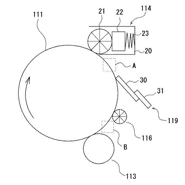
ただし、上記の例示化合物M1〜M14を示す化学式において、Rはアクリロイル基(CH2 =CHCO−)を示し、R’はメタクリロイル基(CH2 =CCH3 CO−)を示す。 However, in the chemical formulas showing the exemplified compounds M1 to M14, R represents an acryloyl group (CH 2 ═CHCO—), and R ′ represents a methacryloyl group (CH 2 ═CCH 3 CO—).
(金属酸化物微粒子)
保護層には、金属酸化物微粒子が含有されていてもよい。また、この金属酸化物微粒子は、表面処理剤によって表面処理されたものであることが好ましい。
(Metal oxide fine particles)
The protective layer may contain metal oxide fine particles. Moreover, it is preferable that the metal oxide fine particles have been surface-treated with a surface treatment agent.
金属酸化物微粒子としては、例えば、シリカ(酸化ケイ素)、酸化マグネシウム、酸化亜鉛、酸化鉛、アルミナ(酸化アルミニウム)、酸化ジルコニウム、酸化錫、チタニア(酸化チタン)、酸化ニオブ、酸化モリブデン、酸化バナジウムなどを用いることができるが、なかでも、硬度、導電性、光透過性の観点から、酸化錫が好ましい。 Examples of the metal oxide fine particles include silica (silicon oxide), magnesium oxide, zinc oxide, lead oxide, alumina (aluminum oxide), zirconium oxide, tin oxide, titania (titanium oxide), niobium oxide, molybdenum oxide, vanadium oxide. Among them, tin oxide is preferable from the viewpoints of hardness, conductivity, and light transmittance.
金属酸化物微粒子の数平均一次粒径は、1〜300nmであることが好ましく、より好ましくは3〜100nmであり、さらに好ましくは5〜40nmである。 The number average primary particle size of the metal oxide fine particles is preferably 1 to 300 nm, more preferably 3 to 100 nm, and still more preferably 5 to 40 nm.
本発明において、金属酸化物微粒子の数平均一次粒径は、走査型電子顕微鏡(日本電子製)により10000倍の拡大写真を撮影し、ランダムに300個の粒子をスキャナーにより取り込んだ写真画像(凝集粒子は除いた)を自動画像処理解析装置「LUZEX AP(ソフトウエアバージョン Ver.1.32)」((株)ニレコ製)を使用して数平均一次粒径を算出した。 In the present invention, the number average primary particle size of the metal oxide fine particles is a photographic image obtained by taking a magnified photograph of 10,000 times with a scanning electron microscope (manufactured by JEOL Ltd.) and randomly capturing 300 particles with a scanner (aggregation). The number average primary particle size was calculated using an automatic image processing analyzer “LUZEX AP (software version Ver. 1.32)” (manufactured by Nireco Corporation).
表面処理剤としては、金属酸化物微粒子の表面に存在するヒドロキシ基などと反応するものが好ましく、このような表面処理剤としては、例えば、シランカップリング剤、チタンカップリング剤などが挙げられる。
また、表面処理剤としては、ラジカル重合性反応基を有する表面処理剤が好ましい。ラジカル重合性反応基としては、例えば、ビニル基、アクリロイル基、メタクリロイル基などが挙げられる。このようなラジカル重合性反応基は、本発明に係る重合性化合物とも反応して強固な保護層を形成することができる。ラジカル重合性反応基を有する表面処理剤としては、ビニル基、アクリロイル基、メタクリロイル基などのラジカル重合性反応基を有するシランカップリング剤が好ましい。
As the surface treatment agent, those that react with a hydroxy group or the like present on the surface of the metal oxide fine particles are preferable. Examples of such a surface treatment agent include a silane coupling agent and a titanium coupling agent.
Moreover, as a surface treating agent, the surface treating agent which has a radically polymerizable reactive group is preferable. Examples of the radical polymerizable reactive group include a vinyl group, an acryloyl group, and a methacryloyl group. Such a radical polymerizable reactive group can react with the polymerizable compound according to the present invention to form a strong protective layer. As the surface treatment agent having a radical polymerizable reactive group, a silane coupling agent having a radical polymerizable reactive group such as a vinyl group, an acryloyl group, or a methacryloyl group is preferable.
以下、表面処理剤の具体例を示す。 Hereinafter, specific examples of the surface treatment agent will be shown.
S−1:CH2 =CHSi(CH3 )(OCH3 )2
S−2:CH2 =CHSi(OCH3 )3
S−3:CH2 =CHSiCl3
S−4:CH2 =CHCOO(CH2 )2 Si(CH3 )(OCH3 )2
S−5:CH2 =CHCOO(CH2 )2 Si(OCH3 )3
S−6:CH2 =CHCOO(CH2 )2 Si(OC2 H5 )(OCH3 )2
S−7:CH2 =CHCOO(CH2 )3 Si(OCH3 )3
S−8:CH2 =CHCOO(CH2 )2 Si(CH3 )Cl2
S−9:CH2 =CHCOO(CH2 )2 SiCl3
S−10:CH2 =CHCOO(CH2 )3 Si(CH3 )Cl2
S−11:CH2 =CHCOO(CH2 )3 SiCl3
S−12:CH2 =C(CH3 )COO(CH2 )2 Si(CH3 )(OCH3 )2
S−13:CH2 =C(CH3 )COO(CH2 )2 Si(OCH3 )3
S−14:CH2 =C(CH3 )COO(CH2 )3 Si(CH3 )(OCH3 )2
S−15:CH2 =C(CH3 )COO(CH2 )3 Si(OCH3 )3
S−16:CH2 =C(CH3 )COO(CH2 )2 Si(CH3 )Cl2
S−17:CH2 =C(CH3 )COO(CH2 )2 SiCl3
S−18:CH2 =C(CH3 )COO(CH2 )3 Si(CH3 )Cl2
S−19:CH2 =C(CH3 )COO(CH2 )3 SiCl3
S−20:CH2 =CHSi(C2 H5 )(OCH3 )2
S−21:CH2 =C(CH3 )Si(OCH3 )3
S−22:CH2 =C(CH3 )Si(OC2 H5 )3
S−23:CH2 =CHSi(OCH3 )3
S−24:CH2 =C(CH3 )Si(CH3 )(OCH3 )2
S−25:CH2 =CHSi(CH3 )Cl2
S−26:CH2 =CHCOOSi(OCH3 )3
S−27:CH2 =CHCOOSi(OC2 H5 )3
S−28:CH2 =C(CH3 )COOSi(OCH3 )3
S−29:CH2 =C(CH3 )COOSi(OC2 H5 )3
S−30:CH2 =C(CH3 )COO(CH2 )3 Si(OC2 H5 )3
S−31:CH2 =CHCOO(CH2 )2 Si(CH3 )2 (OCH3 )
S−32:CH2 =CHCOO(CH2 )2 Si(CH3 )(OCOCH3 )2
S−33:CH2 =CHCOO(CH2 )2 Si(CH3 )(ONHCH3 )2
S−34:CH2 =CHCOO(CH2 )2 Si(CH3 )(OC6 H5 )2
S−35:CH2 =CHCOO(CH2 )2 Si(C10H21)(OCH3 )2
S−36:CH2 =CHCOO(CH2 )2 Si(CH2 C6 H5 )(OCH3 )2
S-1: CH 2 = CHSi (CH 3) (OCH 3) 2
S-2: CH 2 = CHSi (OCH 3) 3
S-3: CH 2 = CHSiCl 3
S-4: CH 2 = CHCOO (CH 2) 2 Si (CH 3) (OCH 3) 2
S-5: CH 2 = CHCOO (CH 2) 2 Si (OCH 3) 3
S-6: CH 2 = CHCOO (CH 2) 2 Si (OC 2 H 5) (OCH 3) 2
S-7: CH 2 = CHCOO (CH 2) 3 Si (OCH 3) 3
S-8: CH 2 = CHCOO (CH 2) 2 Si (CH 3) Cl 2
S-9: CH 2 = CHCOO (CH 2) 2 SiCl 3
S-10: CH 2 = CHCOO (CH 2) 3 Si (CH 3) Cl 2
S-11: CH 2 = CHCOO (CH 2 ) 3 SiCl 3
S-12: CH 2 = C (CH 3) COO (CH 2) 2 Si (CH 3) (OCH 3) 2
S-13: CH 2 = C (CH 3) COO (CH 2) 2 Si (OCH 3) 3
S-14: CH 2 = C (CH 3) COO (CH 2) 3 Si (CH 3) (OCH 3) 2
S-15: CH 2 = C (CH 3) COO (CH 2) 3 Si (OCH 3) 3
S-16: CH 2 = C (CH 3) COO (CH 2) 2 Si (CH 3) Cl 2
S-17: CH 2 = C (CH 3) COO (CH 2) 2 SiCl 3
S-18: CH 2 = C (CH 3) COO (CH 2) 3 Si (CH 3) Cl 2
S-19: CH 2 = C (CH 3) COO (CH 2) 3 SiCl 3
S-20: CH 2 = CHSi (C 2 H 5) (OCH 3) 2
S-21: CH 2 = C (CH 3) Si (OCH 3) 3
S-22: CH 2 = C (CH 3) Si (OC 2 H 5) 3
S-23: CH 2 = CHSi (OCH 3) 3
S-24: CH 2 = C (CH 3) Si (CH 3) (OCH 3) 2
S-25: CH 2 = CHSi (CH 3) Cl 2
S-26: CH 2 = CHCOOSi (OCH 3) 3
S-27: CH 2 = CHCOOSi (OC 2 H 5) 3
S-28: CH 2 = C (CH 3) COOSi (OCH 3) 3
S-29: CH 2 = C (CH 3) COOSi (OC 2 H 5) 3
S-30: CH 2 = C (CH 3) COO (CH 2) 3 Si (OC 2 H 5) 3
S-31: CH 2 = CHCOO (CH 2) 2 Si (CH 3) 2 (OCH 3)
S-32: CH 2 = CHCOO (CH 2) 2 Si (CH 3) (OCOCH 3) 2
S-33: CH 2 = CHCOO (CH 2) 2 Si (CH 3) (ONHCH 3) 2
S-34: CH 2 = CHCOO (CH 2) 2 Si (CH 3) (OC 6 H 5) 2
S-35: CH 2 = CHCOO (CH 2) 2 Si (C 10 H 21) (OCH 3) 2
S-36: CH 2 = CHCOO (CH 2) 2 Si (CH 2 C 6 H 5) (OCH 3) 2
表面処理剤は1種を単独でまたは2種以上を混合して用いてもよい。 You may use a surface treating agent individually by 1 type or in mixture of 2 or more types.
表面処理剤の使用量は、未処理金属酸化物微粒子100質量部に対して0.1〜200質量部であることが好ましく、より好ましくは7〜70質量部である。 It is preferable that the usage-amount of a surface treating agent is 0.1-200 mass parts with respect to 100 mass parts of untreated metal oxide fine particles, More preferably, it is 7-70 mass parts.
表面処理剤の未処理金属酸化物微粒子に対する処理方法としては、例えば、未処理金属酸化物微粒子と表面処理剤とを含むスラリー(固体粒子の懸濁液)を湿式解砕する方法が挙げられる。この方法により、未処理金属酸化物微粒子の再凝集を防止すると同時に未処理金属酸化物微粒子の表面処理が進行する。その後、溶媒を除去して粉体化する。 Examples of the treatment method for the untreated metal oxide fine particles of the surface treatment agent include a method of wet crushing a slurry (solid particle suspension) containing the untreated metal oxide fine particles and the surface treatment agent. By this method, re-aggregation of the untreated metal oxide fine particles is prevented, and at the same time, the surface treatment of the untreated metal oxide fine particles proceeds. Thereafter, the solvent is removed to form powder.
保護層中の金属酸化物微粒子の含有割合は、架橋重合体100質量部に対して20〜170質量部であることが好ましく、より好ましくは25〜130質量部である。 The content of the metal oxide fine particles in the protective layer is preferably 20 to 170 parts by mass, more preferably 25 to 130 parts by mass with respect to 100 parts by mass of the crosslinked polymer.
保護層には、架橋重合体や金属酸化物微粒子の他に他の成分が含有されていてもよく、例えば各種の酸化防止剤を含有させることができ、各種の滑剤粒子を加えることもできる。例えば、フッ素原子含有樹脂粒子を加えることができる。フッ素原子含有樹脂粒子としては、四フッ化エチレン樹脂、三フッ化塩化エチレン樹脂、六フッ化塩化エチレンプロピレン樹脂、フッ化ビニル樹脂、フッ化ビニリデン樹脂、二フッ化二塩化エチレン樹脂、およびこれらの共重合体の中から1種あるいは2種以上を適宜選択することが好ましいが、特に四フッ化エチレン樹脂、フッ化ビニリデン樹脂が好ましい。 The protective layer may contain other components in addition to the crosslinked polymer and metal oxide fine particles. For example, various antioxidants can be contained, and various lubricant particles can be added. For example, fluorine atom-containing resin particles can be added. Examples of the fluorine atom-containing resin particles include tetrafluoroethylene resin, trifluorinated ethylene chloride resin, hexafluoroethylene chloride propylene resin, vinyl fluoride resin, vinylidene fluoride resin, ethylene difluoride dichloride resin, and these One or two or more types are preferably selected from the copolymers, but tetrafluoroethylene resin and vinylidene fluoride resin are particularly preferable.
保護層は、重合性化合物や金属酸化物微粒子、重合開始剤および必要に応じて他の成分を公知の溶媒に添加して塗布液を調製し、この塗布液を感光層(電荷輸送層)の外周面に塗布して塗膜を形成し、この塗膜を乾燥し、紫外線や電子線などの活性線を照射することによって塗膜中の重合性化合物成分を重合反応させ、硬化させることにより形成することができる。 The protective layer is prepared by adding a polymerizable compound, metal oxide fine particles, a polymerization initiator and, if necessary, other components to a known solvent to prepare a coating solution. This coating solution is used as a photosensitive layer (charge transport layer). Formed by coating the outer peripheral surface to form a coating film, drying this coating film, and irradiating active rays such as ultraviolet rays and electron beams to polymerize and cure the polymerizable compound components in the coating film can do.
以上のような保護層は、重合性化合物間の反応などが進行することにより、架橋型硬化樹脂として形成される。 The protective layer as described above is formed as a cross-linked curable resin by a reaction between polymerizable compounds and the like.
保護層の形成に用いられる溶媒としては、重合性化合物および金属酸化物微粒子を溶解または分散させることができればいずれのものも使用でき、例えば、メタノール、エタノール、n−プロピルアルコール、イソプロピルアルコール、n−ブタノール、t−ブタノール、sec−ブタノール、ベンジルアルコール、トルエン、キシレン、メチレンクロライド、メチルエチルケトン、シクロヘキサン、酢酸エチル、酢酸ブチル、メチルセロソルブ、エチルセロソルブ、テトラヒドロフラン、1−ジオキサン、1,3−ジオキソラン、ピリジンおよびジエチルアミンなどが挙げられるが、これらに限定されるものではない。 As the solvent used for forming the protective layer, any solvent can be used as long as the polymerizable compound and the metal oxide fine particles can be dissolved or dispersed. For example, methanol, ethanol, n-propyl alcohol, isopropyl alcohol, n- Butanol, t-butanol, sec-butanol, benzyl alcohol, toluene, xylene, methylene chloride, methyl ethyl ketone, cyclohexane, ethyl acetate, butyl acetate, methyl cellosolve, ethyl cellosolve, tetrahydrofuran, 1-dioxane, 1,3-dioxolane, pyridine and Although diethylamine etc. are mentioned, it is not limited to these.
保層形成用の塗布液の塗布方法としては、例えば、浸漬コーティング法、スプレーコーティング法、スピンナーコーティング法、ビードコーティング法、ブレードコーティング法、ビームコーティング法、スライドホッパー法、円形スライドホッパー法などの公知の方法が挙げられる。 As a coating method of the coating liquid for forming the protective layer, for example, dip coating method, spray coating method, spinner coating method, bead coating method, blade coating method, beam coating method, slide hopper method, circular slide hopper method, etc. are known. The method is mentioned.
塗膜は、乾燥しないで硬化処理を行ってもよいが、自然乾燥または熱乾燥を行った後、硬化処理を行うことが好ましい。 The coating film may be cured without being dried, but it is preferable to perform the curing treatment after natural drying or heat drying.
乾燥の条件は、溶媒の種類、膜厚などによって適宜選択できる。乾燥温度は、好ましくは室温〜180℃であり、特に好ましくは80〜140℃である。乾燥時間は、好ましくは1分間〜200分間であり、特に好ましくは5分間〜100分間である。 Drying conditions can be appropriately selected depending on the type of solvent, film thickness, and the like. The drying temperature is preferably room temperature to 180 ° C, particularly preferably 80 to 140 ° C. The drying time is preferably 1 minute to 200 minutes, and particularly preferably 5 minutes to 100 minutes.
重合性化合物を反応させる方法としては、電子線開裂で反応する方法、ラジカル重合開始剤を添加して、光、熱で反応する方法などが挙げられる。ラジカル重合開始剤は光重合開始剤、熱重合開始剤のいずれも使用することができる。また、光重合開始剤および熱重合開始剤を併用することもできる。 Examples of the method of reacting the polymerizable compound include a method of reacting by electron beam cleavage and a method of reacting with light and heat by adding a radical polymerization initiator. As the radical polymerization initiator, either a photopolymerization initiator or a thermal polymerization initiator can be used. A photopolymerization initiator and a thermal polymerization initiator can also be used in combination.
熱重合開始剤としては、例えば、2,2’−アゾビスイソブチロニトリル、2,2’−アゾビス(2,4−ジメチルアゾビスバレロニリル)、2,2’−アゾビス(2−メチルブチロニトリル)などのアゾ化合物;過酸化ベンゾイル(BPO)、ジ−tert−ブチルヒドロペルオキシド、tert−ブチルヒドロペルオキシド、過酸化クロロベンゾイル、過酸化ジクロロベンゾイル、過酸化ブロモメチルベンゾイル、過酸化ラウロイルなどの過酸化物などが挙げられる。
光重合開始剤としては、例えば、ジエトキシアセトフェノン、2,2−ジメトキシ−1,2−ジフェニルエタン−1−オン、1−ヒドロキシ−シクロヘキシル−フェニル−ケトン、4−(2−ヒドロキシエトキシ)フェニル−(2−ヒドロキシ−2−プロピル)ケトン、2−ベンジル−2−ジメチルアミノ−1−(4−モルフォリノフェニル)ブタノン−1(「イルガキュアー369」:BASFジャパン社製)、2−ヒドロキシ−2−メチル−1−フェニルプロパン−1−オン、2−メチル−2−モルフォリノ(4−メチルチオフェニル)プロパン−1−オン、1−フェニル−1,2−プロパンジオン−2−(o−エトキシカルボニル)オキシムなどのアセトフェノン系またはケタール系光重合開始剤;ベンゾイン、ベンゾインメチルエーテル、ベンゾインエチルエーテル、ベンゾインイソブチルエーテル、ベンゾインイソプロピルエーテルなどのベンゾインエーテル系光重合開始剤;ベンゾフェノン、4−ヒドロキシベンゾフェノン、o−ベンゾイル安息香酸メチル、2−ベンゾイルナフタレン、4−ベンゾイルビフェニル、4−ベンゾイルフェニールエーテル、アクリル化ベンゾフェノン、1,4−ベンゾイルベンゼンなどのベンゾフェノン系光重合開始剤;2−イソプロピルチオキサントン、2−クロロチオキサントン、2,4−ジメチルチオキサントン、2,4−ジエチルチオキサントン、2,4−ジクロロチオキサントンなどのチオキサントン系光重合開始剤などが挙げられる。
その他の光重合開始剤としては、例えば、エチルアントラキノン、2,4,6−トリメチルベンゾイルジフェニルホスフィンオキサイド、2,4,6−トリメチルベンゾイルフェニルエトキシホスフィンオキサイド、ビス(2,4,6−トリメチルベンゾイル)フェニルホスフィンオキサイド、ビス(2,4−ジメトキシベンゾイル)−2,4,4−トリメチルペンチルホスフィンオキサイド、メチルフェニルグリオキシエステル、9,10−フェナントレン、アクリジン系化合物、トリアジン系化合物、イミダゾール系化合物などが挙げられる。また、光重合促進効果を有する光重合促進剤を単独で、または上記光重合開始剤と併用して用いることもできる。光重合促進剤としては、例えば、トリエタノールアミン、メチルジエタノールアミン、4−ジメチルアミノ安息香酸エチル、4−ジメチルアミノ安息香酸イソアミル、安息香酸(2−ジメチルアミノ)エチル、4,4’−ジメチルアミノベンゾフェノンなどが挙げられる。
Examples of the thermal polymerization initiator include 2,2′-azobisisobutyronitrile, 2,2′-azobis (2,4-dimethylazobisvaleronyl), 2,2′-azobis (2-methyl). Azo compounds such as butyronitrile); benzoyl peroxide (BPO), di-tert-butyl hydroperoxide, tert-butyl hydroperoxide, chlorobenzoyl peroxide, dichlorobenzoyl peroxide, bromomethylbenzoyl peroxide, lauroyl peroxide, etc. And peroxides.
Examples of the photopolymerization initiator include diethoxyacetophenone, 2,2-dimethoxy-1,2-diphenylethane-1-one, 1-hydroxy-cyclohexyl-phenyl-ketone, 4- (2-hydroxyethoxy) phenyl- (2-hydroxy-2-propyl) ketone, 2-benzyl-2-dimethylamino-1- (4-morpholinophenyl) butanone-1 (“Irgacure 369” manufactured by BASF Japan Ltd.), 2-hydroxy-2 -Methyl-1-phenylpropan-1-one, 2-methyl-2-morpholino (4-methylthiophenyl) propan-1-one, 1-phenyl-1,2-propanedione-2- (o-ethoxycarbonyl) Acetophenone or ketal photoinitiators such as oximes; benzoin, benzoin methyl ether Benzoin ether photopolymerization initiators such as benzoin ethyl ether, benzoin isobutyl ether, benzoin isopropyl ether; benzophenone, 4-hydroxybenzophenone, methyl o-benzoylbenzoate, 2-benzoylnaphthalene, 4-benzoylbiphenyl, 4-benzoyl Benzophenone photopolymerization initiators such as phenyl ether, acrylated benzophenone, 1,4-benzoylbenzene; 2-isopropylthioxanthone, 2-chlorothioxanthone, 2,4-dimethylthioxanthone, 2,4-diethylthioxanthone, 2,4- Examples thereof include thioxanthone photopolymerization initiators such as dichlorothioxanthone.
Examples of other photopolymerization initiators include ethyl anthraquinone, 2,4,6-trimethylbenzoyldiphenylphosphine oxide, 2,4,6-trimethylbenzoylphenylethoxyphosphine oxide, and bis (2,4,6-trimethylbenzoyl). Phenylphosphine oxide, bis (2,4-dimethoxybenzoyl) -2,4,4-trimethylpentylphosphine oxide, methylphenylglyoxyester, 9,10-phenanthrene, acridine compounds, triazine compounds, imidazole compounds, etc. Can be mentioned. In addition, a photopolymerization accelerator having a photopolymerization promoting effect can be used alone or in combination with the photopolymerization initiator. Examples of the photopolymerization accelerator include triethanolamine, methyldiethanolamine, ethyl 4-dimethylaminobenzoate, isoamyl 4-dimethylaminobenzoate, (2-dimethylamino) ethyl benzoate, and 4,4′-dimethylaminobenzophenone. Etc.
ラジカル重合開始剤としては、光重合開始剤が好ましく、中でも、アルキルフェノン系化合物、またはホスフィンオキサイド系化合物が好ましい。特に、α−アミノアルキルフェノン構造、または、アシルホスフィンオキサイド構造を有する化合物が好ましい。 As the radical polymerization initiator, a photopolymerization initiator is preferable, and an alkylphenone compound or a phosphine oxide compound is particularly preferable. In particular, a compound having an α-aminoalkylphenone structure or an acylphosphine oxide structure is preferable.
重合開始剤は1種を単独でまたは2種以上を混合して用いてもよい。 One polymerization initiator may be used alone, or two or more polymerization initiators may be mixed and used.
重合開始剤の添加割合は、重合性化合物100質量部に対して0.1〜20質量部であることが好ましく、より好ましくは0.5〜10質量部である。 It is preferable that the addition ratio of a polymerization initiator is 0.1-20 mass parts with respect to 100 mass parts of polymeric compounds, More preferably, it is 0.5-10 mass parts.
架橋重合体は、重合性化合物を含む塗膜に活性線を照射し、ラジカルを発生させて重合し、かつ分子間および分子内で架橋反応による架橋結合を形成して硬化することにより生成される。活性線としては紫外線や電子線がより好ましく、紫外線が使用しやすく特に好ましい。 A cross-linked polymer is produced by irradiating a coating film containing a polymerizable compound with active rays, generating radicals, polymerizing, and forming a cross-linking bond by a cross-linking reaction between molecules and within a molecule and curing. . The actinic rays are more preferably ultraviolet rays or electron beams, and ultraviolet rays are particularly preferred because they are easy to use.
紫外線光源としては、紫外線を発生する光源であれば制限なく使用できる。例えば、低圧水銀灯、中圧水銀灯、高圧水銀灯、超高圧水銀灯、カーボンアーク灯、メタルハライドランプ、キセノンランプ、フラッシュ(パルス)キセノンなどを用いることができる。
照射条件はそれぞれのランプによって異なるが、活性線の照射量は、通常5〜500mJ/cm2 、好ましくは5〜100mJ/cm2 である。
ランプの電力は、好ましくは0.1kW〜5kWであり、特に好ましくは、0.5kW〜3kWである。
As the ultraviolet light source, any light source that generates ultraviolet light can be used without limitation. For example, a low pressure mercury lamp, a medium pressure mercury lamp, a high pressure mercury lamp, an ultrahigh pressure mercury lamp, a carbon arc lamp, a metal halide lamp, a xenon lamp, a flash (pulse) xenon, or the like can be used.
Irradiation conditions vary depending on each lamp, but the irradiation amount of active rays is usually 5 to 500 mJ / cm 2 , preferably 5 to 100 mJ / cm 2 .
The power of the lamp is preferably 0.1 kW to 5 kW, particularly preferably 0.5 kW to 3 kW.
電子線源としては、電子線照射装置に格別の制限はなく、一般にはこのような電子線照射用の電子線加速機として、比較的安価で大出力が得られるカーテンビーム方式のものが有効に用いられる。電子線照射の際の加速電圧は、100〜300kVであることが好ましい。吸収線量は、0.5〜10Mradであることが好ましい。 As an electron beam source, there is no particular limitation on the electron beam irradiation apparatus, and generally, an electron beam accelerator for electron beam irradiation is a curtain beam type that is relatively inexpensive and can provide a large output. Used. The acceleration voltage during electron beam irradiation is preferably 100 to 300 kV. The absorbed dose is preferably 0.5 to 10 Mrad.
必要な活性線の照射量を得るための照射時間としては、0.1秒間〜10分間が好ましく、作業効率の観点から0.1秒間〜5分間がより好ましい。 The irradiation time for obtaining the necessary amount of active ray irradiation is preferably 0.1 second to 10 minutes, and more preferably 0.1 second to 5 minutes from the viewpoint of work efficiency.
保護層の形成の工程においては、活性線を照射する前後、および活性線を照射中に乾燥を行うことができ、乾燥を行うタイミングはこれらを組み合わせて適宜選択できる。 In the step of forming the protective layer, drying can be performed before and after irradiation with active rays and during irradiation with active rays, and the timing of drying can be appropriately selected by combining these.
保護層のユニバーサル硬さは、200以上700以下であることが好ましく、より好ましくは280以上600以下である。
保護層のユニバーサル硬さは、超微小硬さ試験機「H100SMC」(フィッシャーインストルメンツ社製)により測定される値である。
なお、保護層のユニバーサル硬さは、保護層を形成する際の硬化処理条件(活性線の照射時間や活性線種)や重合性化合物の種類によって制御することができる。
The universal hardness of the protective layer is preferably 200 or more and 700 or less, more preferably 280 or more and 600 or less.
The universal hardness of the protective layer is a value measured by an ultra micro hardness tester “H100SMC” (manufactured by Fisher Instruments).
The universal hardness of the protective layer can be controlled by the curing treatment conditions (active ray irradiation time and active ray type) when forming the protective layer and the type of polymerizable compound.
保護層の層厚は、0.2〜10μmであることが好ましく、より好ましくは0.5〜6μmである。 The thickness of the protective layer is preferably 0.2 to 10 μm, more preferably 0.5 to 6 μm.
本発明の感光体においては、保護層以外の層は公知の種々のものを採用することができる。 In the photoreceptor of the present invention, various known layers can be employed other than the protective layer.
〔近接帯電手段〕
近接帯電手段113Yは、感光体111Y表面に対して近接帯電方式による帯電を行う手段である。
ここで、近接帯電方式とは、感光体の表面近傍の微小な空隙で発生する近接放電を利用した帯電方式を指す。近接帯電方式には、具体的には、接触ローラ帯電方式、非接触ローラ帯電方式、ブラシ帯電方式などが含まれる。
この例の近接帯電手段113Yは、感光体111Yの表面に接触して配設された帯電ローラと、帯電ローラに電圧を印加する電源とからなる。
帯電ローラは、例えば、導電性支持体上に抵抗調整層が形成されてなるものである。
[Proximity charging means]
The
Here, the proximity charging method refers to a charging method using proximity discharge generated in a minute gap near the surface of the photoreceptor. Specifically, the proximity charging method includes a contact roller charging method, a non-contact roller charging method, a brush charging method, and the like.
The
The charging roller is formed by, for example, forming a resistance adjustment layer on a conductive support.
〔露光手段〕
露光手段115Yは、近接帯電手段113Yによって一様な電位を与えられた感光体111Y表面に、画像信号(イエローの画像信号)に基づいて露光を行い、イエローの画像に対応する静電潜像を形成する手段である。露光手段115Yは、感光体111Yの軸方向にアレイ状に発光素子が配列されたLEDと結像素子とから構成されるもの、あるいはレーザー光学系などが用いられる。
[Exposure means]
The
〔現像手段〕
現像手段117Yは、感光体111Y表面にトナーを供給し、感光体111Y表面に形成された静電潜像を現像し、トナー画像を形成する手段である。この例の現像手段117Yは、具体的には、マグネットを内蔵し現像剤を保持して回転する現像スリーブおよび感光体とこの現像スリーブとの間に現像電界を形成するための直流および/または交流バイアス電圧を印加する電圧印加装置により構成される。
[Development means]
The developing
〔滑剤供給手段〕
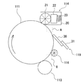
滑剤供給手段114Yは、感光体111Yの表面に滑剤を供給する手段である。滑剤供給手段114Yは、感光体111Yの回転方向においてクリーニング手段1119Yの上流側、具体的には、感光体111Yの回転方向において、転写手段(この例においては一次転写ローラ133Y)の下流側であって、クリーニング手段119Yの上流側に配置されている。
この例の滑剤供給手段114Yは、固形状の滑剤と、ブラシローラよりなる滑剤塗布部材とにより構成される。具体的には、図2に示すように、滑剤供給手段114は、筐体20と、この筐体20内に収容された、直方体形状を有する固形状の滑剤により構成された滑剤ストック22と、感光体111表面に当接し、滑剤ストック22表面を摺擦することにより掻き取った滑剤を感光体111表面に塗布するブラシローラ21と、滑剤ストック22をブラシローラ21に押圧する加圧バネ23とにより構成される。ブラシローラ21は、ブラシの先端が感光体111表面に当接している。また、ブラシローラ21は、感光体111の回転方向とは逆回転で等速に回転駆動される。
[Lubricant supply means]
The lubricant supply means 114Y is a means for supplying a lubricant to the surface of the
The lubricant supply means 114Y in this example is constituted by a solid lubricant and a lubricant application member made of a brush roller. Specifically, as shown in FIG. 2, the lubricant supply means 114 includes a
ブラシローラ21は、例えばポリプロピレンなどの樹脂製のブラシ繊維が高密度に植設されてなる長尺の織布がローラ基体の周面に形成されてなるものである。ブラシローラ21は、各々のブラシ繊維の太さが例えば3〜7デニール、ブラシ繊維の毛長が2〜5mm、ブラシ繊維の電気抵抗率が1×10¹⁰Ω以下、ブラシ繊維のヤング率が1500〜9800N/mm2 、ブラシ繊維の植設密度(単位面積あたりのブラシ繊維数)が例えば50k〜200kF/inch2 のものであることが好ましい。
The
加圧バネ23は、ブラシローラ21の感光体111に対する押圧力が例えば0.5〜1.0Nとなるよう、滑剤ストック22を感光体111に近接する方向に押圧するものが用いられている。
The
滑剤供給手段114においては、感光体111の表面1cm2 当たりに対する塗布量が0.5×10⁻⁷〜1.5×10⁻⁷g/cm2 とされるよう、例えば滑剤ストック22のブラシローラ21に対する押圧力およびブラシローラ21の回転速度が調整される。
In the lubricant supply means 114, for example, the brush roller of the
滑剤としては、例えば、オレイン酸亜鉛、ステアリン酸亜鉛、ステアリン酸カルシウム、などの脂肪酸金属塩を用いることができる。これらの中でも、滑性および延展性の観点から、ステアリン酸亜鉛が好ましい。 As the lubricant, for example, fatty acid metal salts such as zinc oleate, zinc stearate, calcium stearate and the like can be used. Among these, zinc stearate is preferable from the viewpoint of lubricity and spreadability.
〔クリーニング手段〕
クリーニング手段119Yは、感光体111Y表面に残存したトナーを除去する手段である。この例のクリーニング手段119Yは、クリーニングブレードにより構成される。このクリーニングブレードは、図2に示すように、支持部材31と、この支持部材31上に接着層(図示せず)を介して支持されたブレード部材30とにより構成される。ブレード部材30は、その先端が、感光体111表面との当接部分における当該感光体111の回転方向と反対方向(カウンター方向)に向く状態で配置されている。
[Cleaning means]
The
支持部材31としては、特に限定されず、従来公知のものを使用することができ、例えば、剛体の金属、弾性を有する金属、プラスチック、セラミックなどから製造されたものが挙げられる。中でも、剛体の金属が好ましい。
The
ブレード部材30としては、例えば、ベース層とエッジ層とが積層されてなる多層構造のものを用いることができる。ベース層およびエッジ層は、それぞれポリウレタンにより構成されることが好ましい。ポリウレタンとしては、ポリオール、ポリイソシアネートおよび必要に応じて架橋剤を反応させて得られるものなどが挙げられる。
As the
〔滑剤除去手段〕
滑剤除去手段116Yは、感光体111Y表面に付着した滑剤を除去する手段である。滑剤除去手段116Yは、感光体111Yの回転方向においてクリーニング手段1119Yの下流側、具体的には、感光体111Yの回転方向において、クリーニング手段119Yの下流側であって、近接帯電手段113Yの上流側に配置されている。
滑剤除去手段116Yは、除去部材が感光体111Y表面に接触し、機械的作用によって滑剤を除去する手段であることが好ましい。ここで、機械的作用によって滑剤を除去するとは、感光体の表面を機械的に擦るなどによって滑剤を除去するこという。除去部材としては、ブラシローラや発泡ローラなどを用いることができ、除去能力および耐久性の観点からブラシローラが好ましい。この例の滑剤除去手段116Yは、具体的には、感光体111Y表面に当接し、感光体111Yの回転方向とは逆回転で等速に回転駆動されるブラシローラよりなる除去部材と、駆動機構とにより構成される。
[Lubricant removing means]
The
The lubricant removing means 116Y is preferably means for removing the lubricant by a mechanical action when the removing member contacts the surface of the
滑剤除去手段116Yとしてのブラシローラとしては、例えば、基布に繊維の束をパイル糸として織り込んだパイル織り生地をリボン状生地にし、起毛した面を外側にして金属製シャフトの周囲に螺旋状に巻き付け、接着したものが挙げられる。この例のブラシローラは、例えばポリエステルなどの樹脂製のブラシ繊維が高密度に植設されてなる長尺の織布が金属製シャフトの周面に形成されてなるものである。
ブラシ毛は金属製シャフトに対し垂直方向に起毛させる、直毛タイプが除去能力の観点から好ましい。ブラシ毛に用いる糸は、フィラメント糸が望ましく、材料としては、6−ナイロン、12−ナイロン、ポリエステル、アクリル、ビニロン等の合成樹脂が挙げられ、導電性を高める目的でカーボン、ニッケル等の金属を練り込んだものでもよい。ブラシ繊維の太さは3〜15デニールが好ましく、ブラシ繊維の毛長は2〜5mmが好ましい。また、ブラシ繊維の植設密度を4万〜50万本/平方インチ(40k〜500kF/inch2 )の範囲で設定することで、除去に必要な剛性を確保すると共に、ブラシ毛に疎な部分を作らず滑剤の除去ムラを引き起こさないようにすることができる。ブラシ繊維の電気抵抗率は107 Ω以下であることが好ましく、ブラシ繊維のヤング率は1500〜9800N/mm2 であることが好ましい。ブラシローラの感光体に対する食込み量は、0.5〜1.5mmであることが好ましい。ブラシローラの回転速度は例えば感光体速度比で0.3〜1.5とされ、感光体の回転方向と同じ方向の回転であっても、逆の方向の回転であってもよい。
As the brush roller as the lubricant removing means 116Y, for example, a pile woven fabric in which a bundle of fibers is woven into a base fabric as a pile yarn is made into a ribbon-like fabric, and the brushed surface is turned outward and spiral around the metal shaft. Wound and bonded. The brush roller of this example is formed by forming a long woven fabric formed of resin brush fibers such as polyester at a high density on the peripheral surface of a metal shaft.
The brush bristles are preferably raised straight in the direction perpendicular to the metal shaft, from the viewpoint of removal capability. The yarn used for the brush hair is preferably a filament yarn, and examples of the material include synthetic resins such as 6-nylon, 12-nylon, polyester, acrylic, and vinylon, and metals such as carbon and nickel are used for the purpose of increasing conductivity. It may be kneaded. The thickness of the brush fiber is preferably 3 to 15 denier, and the hair length of the brush fiber is preferably 2 to 5 mm. In addition, by setting the density of the brush fibers in the range of 40,000 to 500,000 fibers / square inch (40 k to 500 kF / inch 2 ), the rigidity necessary for removal is secured and the brush hair is sparse. It is possible to prevent the unevenness of the removal of the lubricant without making the lubricant. The electrical resistivity of the brush fiber is preferably 10 7 Ω or less, and the Young's modulus of the brush fiber is preferably 1500 to 9800 N / mm 2 . The biting amount of the brush roller with respect to the photosensitive member is preferably 0.5 to 1.5 mm. The rotational speed of the brush roller is, for example, 0.3 to 1.5 in terms of the photoreceptor speed ratio, and may be in the same direction as that of the photoreceptor or in the opposite direction.
本発明の画像形成装置100においては、図2に示すように、滑剤供給手段114による滑剤の供給後であってクリーニング手段119によるトナーの除去前の感光体111表面の単位面積当たりの滑剤存在比率をA(atom%)、滑剤除去手段116による滑剤の除去後の感光体111表面の単位面積当たりの滑剤存在比率をB(atom%)としたとき、下記式(1)および式(2)を満たす。すなわち、本発明の画像形成装置100においては、滑剤供給手段114および滑剤除去手段116において、下記式(1)および式(2)を満たすように、感光体111表面上の滑剤存在量の調整が行われる。
式(1):A≧5.0B
式(2):B≦0.20
上記式(1)および式(2)をいずれも満たすことにより、クリーニング手段119によるトナーの除去前においては、感光体111表面に滑剤が十分に存在するため、良好なトナークリーニング性が得られ、滑剤除去手段116による滑剤の除去後においては、滑剤が感光体111表面から除去されるため、次の画像形成において、高温高湿環境下で近接帯電方式による帯電が行われても、滑剤の劣化に伴う像流れなどの画像不良を引き起こすことがない。
In the
Formula (1): A ≧ 5.0B
Formula (2): B ≦ 0.20
By satisfying both the above formulas (1) and (2), before the toner is removed by the cleaning means 119, the lubricant is sufficiently present on the surface of the
なお、滑剤存在比率Aの測定では、回転する感光体111において、滑剤供給手段114の下流側であってクリーニング手段119の上流側の感光体111表面上の任意の箇所を選択することができる。
また、滑剤存在比率Bの測定では、回転する感光体111において、滑剤除去手段116の下流側の感光体111表面上の任意の箇所を選択することができるが、本発明においては、滑剤除去手段116の下流側であって近接帯電手段113の上流側の感光体111表面上の任意の箇所を選択することとする。
滑剤存在比率Bは、具体的には、0.20atom%以下の範囲内であれば、感光体表面に付着した滑剤を十分に除去できているといえる。
In the measurement of the lubricant presence ratio A, an arbitrary location on the surface of the
Further, in the measurement of the lubricant presence ratio B, an arbitrary location on the surface of the
Specifically, if the lubricant presence ratio B is in the range of 0.20 atom% or less, it can be said that the lubricant adhering to the surface of the photoreceptor is sufficiently removed.
ここで、滑剤存在比率とは、感光体表面の単位面積当たりに滑剤が存在する度合いをいう。本発明においては、X線光電子分光法(ESCA)によって測定される感光体表面上の滑剤(脂肪酸金属塩)由来の金属の存在比率を代替量として用いる。単位は「atom%」とする。検出する選択元素は、(1)保護層を構成する架橋重合体の元素(C、Oなど)、(2)金属酸化物(例えばSnなど)、(3)感光体表面に供給される滑剤(脂肪酸金属塩)由来の金属(例えばZn、Alなど)とする。これらの選択元素については、保護層を構成する材料の種類や用いる滑剤の種類によって、感光体表面に存在し得ると考えられる元素全てを抽出する必要がある。なお、検知性の観点から、保護層に含有される金属酸化物由来の金属と滑剤由来の金属との差別化のため、使用する金属酸化物と滑剤の金属とは違う種類のものを選択する。
具体的には、感光体から保護層のみ5mm角で切り取り、測定サンプルとする。X線光電子分光装置「K−Alpha」(サーモフィッシャーサイエンティフィック社製)を用い、選択元素を下記測定条件にて定量分析し、各々の原子ピーク面積から相対感度因子を用いて表面元素濃度を算出する。検出される金属の測定量を代替量として取り扱う。
−測定条件
X線:Alモノクロ線源
加速:12kV、6mA
分解能:50eV
ビーム系:400μm
ステップサイズ:0.1eV
Here, the lubricant presence ratio refers to the degree of presence of lubricant per unit area of the photoreceptor surface. In the present invention, the abundance ratio of the metal derived from the lubricant (fatty acid metal salt) on the photoreceptor surface measured by X-ray photoelectron spectroscopy (ESCA) is used as an alternative amount. The unit is “atom%”. Selective elements to be detected are (1) elements (C, O, etc.) of the crosslinked polymer constituting the protective layer, (2) metal oxide (eg, Sn), (3) lubricant supplied to the surface of the photoreceptor ( A metal derived from (fatty acid metal salt) (for example, Zn, Al, etc.). For these selected elements, it is necessary to extract all the elements that can be present on the surface of the photoreceptor depending on the type of material constituting the protective layer and the type of lubricant used. In addition, from the viewpoint of detectability, in order to differentiate between the metal derived from the metal oxide contained in the protective layer and the metal derived from the lubricant, select a different type from the metal oxide used and the metal of the lubricant. .
Specifically, only the protective layer is cut out from the photosensitive member at a 5 mm square to obtain a measurement sample. Using the X-ray photoelectron spectrometer “K-Alpha” (manufactured by Thermo Fisher Scientific), the selected elements are quantitatively analyzed under the following measurement conditions, and the surface element concentration is determined from each atomic peak area using the relative sensitivity factor. calculate. Treat the amount of metal detected as an alternative.
-Measurement conditions X-ray: Al monochrome source acceleration: 12 kV, 6 mA
Resolution: 50eV
Beam system: 400 μm
Step size: 0.1eV
滑剤存在比率Aは、滑剤供給手段による供給方法や供給量によって制御することができる。また、滑剤存在比率Bは、滑剤除去手段による除去部材の種類や除去部材の接触状態によって制御することができる。 The lubricant presence ratio A can be controlled by the supply method or supply amount by the lubricant supply means. Further, the lubricant presence ratio B can be controlled by the type of the removing member by the lubricant removing means and the contact state of the removing member.
中間転写体ユニット130は、感光体111Y、111M、111C、111Bkと当接可能に設けられている。中間転写体ユニット130は、無端ベルト状中間転写体131と、当該無端ベルト状中間転写体131と当接して配置された一次転写ローラ133Y、133M、133C、133Bkと、当該無端ベルト状中間転写体131のクリーニング手段135と、を有する。
The intermediate
この画像形成装置100においては、感光体111Y、111M、111C、111Bk上に形成されたトナー画像を一次転写ローラ(一次転写手段)133Y、133M、133C、133Bkによって中間転写体131に転写し、中間転写体131上に転写された各トナー画像を二次転写ローラ(二次転写手段)217によって転写材Pに転写する中間転写方式が採用されているが、感光体上に形成されたトナー画像を転写手段によって直接転写材に転写する直接転写方式が採用されてもよい。
In this
無端ベルト状中間転写体131は、複数のローラ137A、137B、137C、137Dにより巻回され、回動可能に支持されている。
The endless belt-shaped
この画像形成装置100において、感光体111Y、現像手段117Y、滑剤供給手段114Y、クリーニング手段119Yおよび滑剤除去手段116Yなどは、一体的に結合され、装置本体に着脱自在に構成されたプロセスカートリッジ(画像形成ユニット)であってもよい。あるいは、近接帯電手段113Y、露光手段115Y、現像手段117Y、滑剤供給手段114Y、滑剤除去手段116Y、一次転写ローラ133Yおよびクリーニング手段119Yからなる群から選ばれる一以上の部材と、感光体111Yとが一体的に構成されたプロセスカートリッジ(画像形成ユニット)であってもよい。
In the
プロセスカートリッジ200は、筐体201と、それに収容された感光体111Y、近接帯電手段113Y、現像手段117Y、滑剤供給手段114Y、クリーニング手段119Yおよび滑剤除去手段116Yと、中間転写体ユニット130と、を有する。また、装置本体には、プロセスカートリッジ200を装置本体内にガイドする手段として支持レール203L、203Rが設けられている。それにより、プロセスカートリッジ200を装置本体に着脱可能となっている。これらのプロセスカートリッジ200は、装置本体に着脱自在に構成された単一の画像形成ユニットとなりうる。
The
給紙搬送手段150は、給紙カセット211内の転写材Pを、複数の中間ローラ213A、213B、213C、213Dおよびレジストローラ215を経て、二次転写ローラ217に搬送可能に設けられている。
The sheet feeding / conveying
定着手段170は、二次転写ローラ217により転写されたカラー画像を定着処理する。排紙ローラ219は、定着処理された転写材Pを挟持して、排紙トレイ221上に載置可能に設けられている。
The fixing
このように構成された画像形成装置100では、画像形成ユニット110Y、110M、110C、110Bkによりトナー画像を形成する。具体的には、近接帯電手段113Y、113M、113C、113Bkにより感光体111Y、111M、111C、111Bkの表面に放電して負に帯電させる。次いで、露光手段115Y、115M、115C、115Bkで、感光体111Y、111M、111C、111Bkの表面を画像信号に基づいて露光し、静電潜像を形成する。次いで、現像手段117Y、117M、117C、117Bkで、感光体111Y、111M、111C、111Bkの表面にトナーを付与して現像し、トナー画像を形成する。
In the
次いで、一次転写ローラ(一次転写手段)133Y、133M、133C、133Bkを、回動する無端ベルト状中間転写体131と当接させる。それにより、感光体111Y、111M、111C、111Bk上にそれぞれ形成した各色のトナー画像を、回動する無端ベルト状中間転写体131上に逐次転写させて、カラー画像を転写する(一次転写する)。画像形成処理中、一次転写ローラ133Bkは、常時、感光体111Bkに当接する。一方、他の一次転写ローラ133Y、133M、133Cは、カラー画像形成時にのみ、それぞれ対応する感光体111Y、111M、111Cに当接する。
Next, primary transfer rollers (primary transfer means) 133Y, 133M, 133C, and 133Bk are brought into contact with the rotating endless belt-shaped
そして、一次転写ローラ133Y、133M、133C、133Bkと無端ベルト状中間転写体131とを分離させた後、滑剤供給手段114Y、114M、114C、114Bkにより感光体111Y、111M、111C、111Bkの表面に滑剤を供給する。その後、感光体111Y、111M、111C、111Bkの表面に残存したトナーを、クリーニング手段119Y、119M、119C、119Bkで除去する。そして、感光体111Y、111M、111C、111Bkの表面に残存した滑剤を、滑剤除去手段116Y、116M、116C、116Bkで除去する。その後、次の画像形成に備えて、必要に応じて感光体111Y、111M、111C、111Bkの表面を除電手段(不図示)によって除電した後、近接帯電手段113Y、113M、113C、113Bkにより負に帯電させる。
Then, after separating the primary transfer rollers 133Y, 133M, 133C, and 133Bk and the endless belt-shaped
一方、給紙カセット211内に収容された転写材P(例えば普通紙、透明シートなどの最終画像を担持する支持体)を、給紙搬送手段150で給紙し、複数の中間ローラ213A、213B、213C、213D、レジストローラ215を経て二次転写ローラ(二次転写手段)217に搬送する。そして、二次転写ローラ217を回動する無端ベルト状中間転写体131と当接させて、転写材P上にカラー画像を一括して転写する(二次転写する)。二次転写ローラ217は、転写材P上に二次転写を行うときのみ、無端ベルト状中間転写体131と当接する。その後、カラー画像が一括転写された転写材Pを、無端ベルト状中間転写体131の曲率が高い部位で分離する。
On the other hand, a transfer material P (for example, a support for carrying a final image such as plain paper or a transparent sheet) accommodated in a
このようにしてカラー画像が一括して転写された転写材Pを、定着手段170で定着処理した後、排紙ローラ219で挟持して装置外の排紙トレイ221上に載置する。また、カラー画像が一括転写された転写材Pを無端ベルト状中間転写体131から分離した後、クリーニング手段135で無端ベルト状中間転写体131上の残存トナーを除去する。
The transfer material P onto which the color images have been transferred in this way is fixed by the fixing
以上、本発明の画像形成装置100によれば、滑剤供給手段114による滑剤の供給後であってクリーニング手段119によるトナーの除去前の感光体表面の単位当たりの滑剤存在比率をA(atom%)、滑剤除去手段116による滑剤の除去後の感光体表面の単位当たりの滑剤存在比率をB(atom%)としたとき、A≧5.0B、かつ、B≦0.20を満たすことにより、良好なトナークリーニング性を有すると共に、高温高湿環境下において像流れの発生を抑制することができる。
As described above, according to the
〔トナー〕
本発明の画像形成装置において使用されるトナーとしては、特に限定されないが、結着樹脂および着色剤が含有されるトナー粒子よりなり、当該トナー粒子には、所望により離型剤などの他の成分が含有されていてもよい。
トナーを構成するトナー粒子は、高画質化を企図する観点からすれば、その体積平均粒径が2〜8μmであることが好ましい。
〔toner〕
The toner used in the image forming apparatus of the present invention is not particularly limited, and includes toner particles containing a binder resin and a colorant. The toner particles may include other components such as a release agent as desired. May be contained.
The toner particles constituting the toner preferably have a volume average particle diameter of 2 to 8 μm from the viewpoint of achieving high image quality.
上記のトナーを製造する方法としては、特に制約されないが、例えば、通常の粉砕法や、分散媒中で作成する湿式溶融球形化法や、懸濁重合、分散重合、乳化重合凝集法等の既知の重合法などが挙げられる。 The method for producing the toner is not particularly limited. For example, a known pulverization method, a wet melt spheronization method prepared in a dispersion medium, suspension polymerization, dispersion polymerization, emulsion polymerization aggregation method and the like are known. And the like.
また、トナー粒子には、外添剤として、平均粒径10〜300nm程度のシリカおよびチタニア等の無機微粒子、0.2〜3μm程度の研磨剤を適宜量、外部添加することができる。 In addition, an appropriate amount of inorganic fine particles such as silica and titania having an average particle diameter of about 10 to 300 nm and an abrasive of about 0.2 to 3 μm can be externally added to the toner particles as external additives.
トナーは、磁性または非磁性の一成分現像剤として使用することもできるが、キャリアと混合して二成分現像剤として使用してもよい。
トナーを二成分現像剤として使用する場合において、キャリアとしては、鉄などの強磁性金属、強磁性金属とアルミニウムおよび鉛などの合金、フェライトおよびマグネタイトなどの強磁性金属の化合物などの従来公知の材料からなる磁性粒子を用いることができ、特にフェライトが好ましい。
The toner can be used as a magnetic or nonmagnetic one-component developer, but may be mixed with a carrier and used as a two-component developer.
In the case where the toner is used as a two-component developer, the carrier may be a conventionally known material such as a ferromagnetic metal such as iron, an alloy such as ferromagnetic metal and aluminum and lead, and a compound of ferromagnetic metal such as ferrite and magnetite. In particular, ferrite is preferable.
〔画像形成方法〕
本発明の画像形成方法は、本発明の画像形成装置を用いて実行することができる。具体的には、重合性化合物を硬化して得られる架橋重合体を含有する保護層を有する感光体の表面に近接帯電方式による帯電を行う近接帯電工程と、近接帯電工程により帯電された感光体を露光する露光工程と、露光工程により露光された感光体にトナーを供給してトナー画像を形成する現像工程と、感光体上に形成されたトナー画像を転写する転写工程と、感光体の表面に滑剤を供給する滑剤供給工程と、感光体の表面に残存したトナーを除去するクリーニング工程と、滑剤を感光体の表面より除去する滑剤除去工程とを有し、滑剤供給工程は、転写工程の後であって、クリーニング工程の前に行われ、滑剤除去工程は、クリーニング工程の後であって、近接帯電工程の前に行われる。本発明の画像形成方法においては、滑剤供給工程の後であってクリーニング工程の前の感光体表面の単位面積当たりの滑剤存在比率をA(atom%)、滑剤除去工程の後の感光体表面の単位面積当たりの滑剤存在比率をB(atom%)としたとき、上記式(1)および式(2)を満たす。すなわち、本発明の画像形成方法においては、滑剤供給工程および滑剤除去工程において、上記式(1)および式(2)を満たすように感光体表面上の滑剤存在量の調整が行われる。
(Image forming method)
The image forming method of the present invention can be executed using the image forming apparatus of the present invention. Specifically, a proximity charging step of charging the surface of a photoreceptor having a protective layer containing a crosslinked polymer obtained by curing a polymerizable compound by a proximity charging method, and a photoreceptor charged by the proximity charging step An exposure step for exposing the photosensitive member, a developing step for supplying toner to the photoconductor exposed by the exposure step to form a toner image, a transfer step for transferring the toner image formed on the photoconductor, and the surface of the photoconductor A lubricant supplying step for supplying the lubricant to the surface, a cleaning step for removing the toner remaining on the surface of the photoconductor, and a lubricant removing step for removing the lubricant from the surface of the photoconductor. Later, before the cleaning step, the lubricant removal step is performed after the cleaning step and before the proximity charging step. In the image forming method of the present invention, the ratio of the lubricant present per unit area of the photoreceptor surface after the lubricant supplying step and before the cleaning step is A (atom%), and the surface of the photoreceptor surface after the lubricant removing step is used. When the lubricant presence ratio per unit area is B (atom%), the above formulas (1) and (2) are satisfied. That is, in the image forming method of the present invention, the amount of lubricant present on the photoreceptor surface is adjusted so as to satisfy the above formulas (1) and (2) in the lubricant supply step and the lubricant removal step.
本発明の画像形成方法の滑剤供給工程においては、図1に示す画像形成装置のように、滑剤供給手段によって滑剤が感光体に供給されてもよいが、トナーに対して外部添加された微粉状の滑剤が、現像工程において形成される現像電界の作用により感光体に供給されてもよい。
トナーに対して外部添加される微粉状の滑剤としては、滑性、劈開性を有するものであれば特に限定されないが、例えば、ステアリン酸亜鉛などを用いることができる。滑剤の数平均一次粒径は、例えば1〜20μmであることが好ましい。また、滑剤は、トナーの帯電性に影響を与えないよう、トナーに対して0.01〜0.3質量%の割合で添加されることが好ましい。
In the lubricant supply step of the image forming method of the present invention, the lubricant may be supplied to the photoreceptor by the lubricant supply means as in the image forming apparatus shown in FIG. The lubricant may be supplied to the photoreceptor by the action of a developing electric field formed in the developing step.
The fine powder lubricant externally added to the toner is not particularly limited as long as it has lubricity and cleavage, but for example, zinc stearate can be used. The number average primary particle size of the lubricant is preferably 1 to 20 μm, for example. Further, the lubricant is preferably added at a ratio of 0.01 to 0.3% by mass with respect to the toner so as not to affect the chargeability of the toner.
本発明の画像形成方法によれば、滑剤供給工程の後であってクリーニング工程の前の感光体表面の単位当たりの滑剤存在比率をA(atom%)、滑剤除去工程の後の感光体表面の単位当たりの滑剤存在比率をB(atom%)としたとき、A≧5.0B、かつ、B≦0.20を満たすことにより、良好なトナークリーニング性を有すると共に、高温高湿環境下において像流れの発生を抑制することができる。 According to the image forming method of the present invention, the ratio of the lubricant per unit of the photoreceptor surface after the lubricant supplying process and before the cleaning process is A (atom%), and the surface of the photoreceptor surface after the lubricant removing process is used. When the ratio of lubricant per unit is B (atom%), satisfying A ≧ 5.0B and B ≦ 0.20, the toner has a good toner cleaning property and is imaged in a high temperature and high humidity environment. Flow generation can be suppressed.
以下、実施例を挙げて本発明を詳細に説明するが、本発明は以下の実施例のみに限定されるものではない。なお、下記中「部」とは「質量部」を示す。 EXAMPLES Hereinafter, although an Example is given and this invention is demonstrated in detail, this invention is not limited only to a following example. In the following, “part” means “part by mass”.
〔感光体の作製例1〕
直径60mmのアルミニウム製の円筒体の表面を切削加工し、表面を細かく粗面にした導電性支持体〔1〕を用意した。
[Photosensitive body preparation example 1]
The surface of an aluminum cylinder having a diameter of 60 mm was cut to prepare a conductive support [1] having a fine and rough surface.
(中間層の形成)
下記組成の分散液を下記溶媒と同じ溶媒にて二倍に希釈し、一夜静置後に濾過(フィルター;日本ポール社製リジメッシュ5μmフィルター使用)し、中間層形成用塗布液〔1〕を調製した。
バインダー樹脂:ポリアミド樹脂「CM8000」(東レ社製) 1部
金属酸化物粒子:酸化チタン「SMT500SAS」(テイカ社製) 3部
溶媒:メタノール 10部
分散機としてサンドミルを用いて、バッチ式で10時間の分散を行った。
中間層形成用塗布液〔1〕を用いて導電性支持体〔1〕上に、浸漬コーティング法で塗布し、乾燥膜厚2μmの中間層〔1〕を形成した。
(Formation of intermediate layer)
A dispersion having the following composition was diluted twice with the same solvent as described below, and allowed to stand overnight, followed by filtration (filter; using a lymesh 5 μm filter manufactured by Nihon Pall Co., Ltd.) to prepare an intermediate layer forming coating solution [1]. .
Binder resin: Polyamide resin “CM8000” (manufactured by Toray Industries, Inc.) 1 part Metal oxide particles: Titanium oxide “SMT500SAS” (manufactured by Teica) 3 parts Solvent: Methanol 10 parts Batch using a sand mill as a disperser for 10 hours Was distributed.
An intermediate layer [1] having a dry film thickness of 2 μm was formed on the conductive support [1] using the intermediate layer forming coating solution [1] by dip coating.
(電荷発生層の形成)
電荷発生物質:下記顔料(CG−1)20部、バインダー樹脂:ポリビニルブチラール樹脂「#6000−C」(電気化学工業社製)10部、溶媒:酢酸t−ブチル700部、溶媒:4−メトキシ−4−メチル−2−ペンタノン300部を混合し、サンドミルを用いて10時間分散し、電荷発生層形成用塗布液〔1〕を調製した。この電荷発生層形成塗布液〔1〕を中間層〔1〕上に浸漬コーティング法で塗布し、乾燥膜厚0.3μmの電荷発生層〔1〕を形成した。
(Formation of charge generation layer)
Charge generation material: 20 parts of the following pigment (CG-1), binder resin: 10 parts of polyvinyl butyral resin “# 6000-C” (manufactured by Denki Kagaku Kogyo), solvent: 700 parts of t-butyl acetate, solvent: 4-methoxy 300 parts of -4-methyl-2-pentanone was mixed and dispersed for 10 hours using a sand mill to prepare a coating solution [1] for forming a charge generation layer. This charge generation layer forming coating solution [1] was applied onto the intermediate layer [1] by a dip coating method to form a charge generation layer [1] having a dry film thickness of 0.3 μm.
<顔料(CG−1)の合成>
(1)無定形チタニルフタロシアニンの合成
1,3−ジイミノイソインドリン;29.2部をo−ジクロロベンゼン200部に分散し、チタニウムテトラ−n−ブトキシド;20.4部を加えて窒素雰囲気下に150〜160℃で5時間加熱した。放冷後、析出した結晶を濾過し、クロロホルムで洗浄、2%塩酸水溶液で洗浄、水洗メタノール洗浄して、乾燥後、26.2部(収率91%)の粗チタニルフタロシアニンを得た。
次いで、粗チタニルフタロシアニンを5℃以下において濃硫酸250部中で1時間攪拌して溶解し、これを20℃の水5000部に注いだ。析出した結晶をろ過し、充分に水洗してウエットペースト品225部を得た。
このウエットペースト品を冷凍庫にて凍結し、再度解凍した後、ろ過、乾燥して無定形チタニルフタロシアニン24.8部(収率86%)を得た。
<Synthesis of Pigment (CG-1)>
(1) Synthesis of amorphous titanyl phthalocyanine 1,3-diiminoisoindoline; 29.2 parts are dispersed in 200 parts of o-dichlorobenzene, and titanium tetra-n-butoxide; 20.4 parts are added under a nitrogen atmosphere. For 5 hours at 150-160 ° C. After allowing to cool, the precipitated crystals were filtered, washed with chloroform, washed with 2% aqueous hydrochloric acid, washed with water, washed with methanol, and dried to obtain 26.2 parts (yield 91%) of crude titanyl phthalocyanine.
Next, the crude titanyl phthalocyanine was dissolved by stirring for 1 hour in 250 parts of concentrated sulfuric acid at 5 ° C. or less, and this was poured into 5000 parts of water at 20 ° C. The precipitated crystals were filtered and sufficiently washed with water to obtain 225 parts of a wet paste product.
This wet paste product was frozen in a freezer, thawed again, filtered and dried to obtain 24.8 parts of amorphous titanyl phthalocyanine (yield 86%).
(2)(2R,3R)−2,3−ブタンジオール付加体チタニルフタロシアニン(CG−1)の合成
上記無定形チタニルフタロシアニン10.0部と(2R,3R)−2,3−ブタンジオール0.94部(0.6当量比)(当量比はチタニルフタロシアニンに対する当量比、以後同じ)をオルトクロロベンゼン(ODB)200部中に混合し60〜70℃で6.0時間加熱撹拌した。一夜放置後、該反応液にメタノールを加えて生じた結晶を濾過し、濾過後の結晶をメタノールで洗って((2R,3R)−2,3−ブタンジオール付加体チタニルフタロシアニンを含有する顔料)CG−1:10.3部を得た。顔料(CG−1)のX線回折スペクトルでは、8.3°、24.7°、25.1°、26.5°に明確なピークがある。マススペクトルにおいて576と648にピークがあり、IRスペクトルでは970cm-1付近のTi=O、630cm-1付近にO−Ti−Oの両吸収が現れる。また熱分析(TG)では390〜410℃に約7%の質量減少があることから、チタニルフタロシアニンと(2R,3R)−2,3−ブタンジオールの1:1付加体と非付加体(付加していない)チタニルフタロシアニンの混合物と推定される。
得られた顔料(CG−1)のBET比表面積を流動式比表面積自動測定装置(マイクロメトリックス・フローソープ型:島津製作所)で測定したところ、31.2m2 /gであった。
(2) Synthesis of (2R, 3R) -2,3-butanediol adduct titanyl phthalocyanine (CG-1) 10.0 parts of the above amorphous titanyl phthalocyanine and (2R, 3R) -2,3-butanediol 94 parts (0.6 equivalent ratio) (equivalent ratio is equivalent ratio to titanyl phthalocyanine, hereinafter the same) was mixed in 200 parts of orthochlorobenzene (ODB) and stirred at 60 to 70 ° C. for 6.0 hours. After standing overnight, methanol was added to the reaction solution, and the resulting crystals were filtered. The crystals after filtration were washed with methanol (a pigment containing (2R, 3R) -2,3-butanediol adduct titanyl phthalocyanine). CG-1: 10.3 parts were obtained. In the X-ray diffraction spectrum of the pigment (CG-1), there are clear peaks at 8.3 °, 24.7 °, 25.1 °, and 26.5 °. There is a peak in the 576 and 648 in the mass spectra, O-Ti-O both absorption appears Ti = O near 970 cm -1, around 630 cm -1 in the IR spectrum. In addition, since thermal analysis (TG) has a mass loss of about 7% at 390 to 410 ° C., a 1: 1 adduct and a non-adduct (addition) of titanyl phthalocyanine and (2R, 3R) -2,3-butanediol (Not) presumed to be a mixture of titanyl phthalocyanine.
It was 31.2 m < 2 > / g when the BET specific surface area of the obtained pigment (CG-1) was measured with the flow type specific surface area automatic measuring apparatus (Micrometrics flow soap type: Shimadzu Corporation).
(電荷輸送層の形成)
電荷輸送物質:下記化合物A225部、バインダー樹脂:ポリカーボネート樹脂「Z300」(三菱ガス化学社製)300部、酸化防止剤:「Irganox1010」(日本チバガイギー社製)6部、溶媒:THF(テトラヒドロフラン)1600部、溶媒:トルエン400部、シリコーンオイル「KF−50」(信越化学社製)1部を混合し、溶解して電荷輸送層形成用塗布液〔1〕を調製した。
この電荷輸送層形成用塗布液〔1〕を電荷発生層〔1〕の上に円形スライドホッパー塗布装置を用いて塗布し、乾燥膜厚20μmの電荷輸送層〔1〕を形成した。
(Formation of charge transport layer)
Charge transport material: 225 parts of the following compound A, binder resin: 300 parts of polycarbonate resin “Z300” (manufactured by Mitsubishi Gas Chemical), antioxidant: 6 parts of “Irganox 1010” (manufactured by Ciba Geigy Japan), solvent: THF (tetrahydrofuran) 1600 Part, solvent: 400 parts of toluene and 1 part of silicone oil “KF-50” (manufactured by Shin-Etsu Chemical Co., Ltd.) were mixed and dissolved to prepare a coating solution [1] for forming a charge transport layer.
The charge transport layer forming coating solution [1] was applied onto the charge generation layer [1] using a circular slide hopper coating apparatus to form a charge transport layer [1] having a dry film thickness of 20 μm.
(保護層の形成)
(1)金属酸化物微粒子の作製
酸化錫(数平均一次粒径:20nm)100部、表面処理剤として上記例示化合物(S−13)30部、トルエン/イソプロピルアルコール=1/1(質量比)の混合溶媒300部の混合液を、ジルコニアビーズとともにサンドミルに入れ約40℃で、回転速度1500rpmで撹拌し、さらに、上記処理混合物を取り出し、ヘンシェルミキサーに投入して回転速度1500rpmで15分間撹拌した後、120℃で3時間乾燥することによって、ラジカル重合性官能基を有する化合物による酸化錫の表面処理を終了し、表面処理済み酸化錫を得た。これを金属酸化物微粒子〔1〕とする。上記のラジカル重合性官能基を有する化合物による表面処理により、酸化錫の粒子表面は上記例示化合物(S−13)により被覆されていた。
(Formation of protective layer)
(1) Preparation of metal oxide
(2)保護層の形成
金属酸化物微粒子〔1〕100部、重合性化合物:上記例示化合物(M1)100部、溶媒:sec−ブタノール320部、溶媒:THF(テトラヒドロフラン)80部を遮光下で混合し、分散機としてサンドミルを用いて5時間分散した後、重合開始剤:「イルガキュアー」(BASFジャパン社製)10部を加え、遮光下で撹拌して溶解させ、保護層形成用塗布液〔1〕を調製した。この保護層形成用塗布液〔1〕を電荷輸送層〔1〕上に円形スライドホッパー塗布装置を用いて塗布して塗膜を形成した。その後、この塗膜を室温で15分間乾燥し、キセノンランプを用いて窒素気流下において、光源と塗膜との間の離間距離を10mmとして、ランプ出力1kWで紫外線を1分間照射して、乾燥膜厚3.0μmの保護層〔1〕を形成し感光体〔1〕を作製した。この感光体〔1〕における保護層のユニバーサル硬さは280であった。
(2) Formation of
〔感光体の作製例2〕
感光体の作製例1の保護層の形成において、用いる重合性化合物を上記例示化合物(M8)に変更したことの他は同様にして感光体〔2〕を作製した。この感光体〔2〕における保護層のユニバーサル硬さは200であった。
[Photoconductor Preparation Example 2]
Photoreceptor [2] was produced in the same manner as in the formation of the protective layer in Production Example 1 of the photoreceptor except that the polymerizable compound used was changed to the exemplified compound (M8). The universal hardness of the protective layer in this photoreceptor [2] was 200.
〔感光体の作製例3〕
感光体の作製例1の保護層の形成において、塗膜乾燥後に用いる光源をメタルハライドランプに変更し、また、光源と塗膜との間の離間距離を100mmに、ランプ出力を4kWに変更したことの他は同様にして感光体〔3〕を作製した。この感光体〔3〕における保護層のユニバーサル硬さは400であった。
[Photoconductor Preparation Example 3]
In the formation of the protective layer in Preparation Example 1 of the photoreceptor, the light source used after drying the coating film was changed to a metal halide lamp, the separation distance between the light source and the coating film was changed to 100 mm, and the lamp output was changed to 4 kW. A photoreceptor [3] was prepared in the same manner as above. The universal hardness of the protective layer in this photoreceptor [3] was 400.
〔感光体の作製例4〕
感光体の作製例1の保護層の形成において、用いる重合性化合物を上記例示化合物(M11)に変更したことの他は同様にして感光体〔4〕を作製した。この感光体〔4〕における保護層のユニバーサル硬さは550であった。
[Photoconductor Preparation Example 4]
Photoreceptor [4] was produced in the same manner as in the formation of the protective layer in Production Example 1 of the photoreceptor, except that the polymerizable compound used was changed to the exemplified compound (M11). The universal hardness of the protective layer in this photoreceptor [4] was 550.
<実施例1>
画像形成装置「bizhub C6500」(コニカミノルタ社製)に、所定の現像剤と感光体〔1〕とを搭載し、画像形成ユニットを近接帯電による帯電が行われるよう、接触ローラ帯電方式に改造し、さらにクリーニング手段の下流側に下記仕様の滑剤除去手段を設置した。この滑剤除去手段を下記条件〔1〕に設定した。なお、この装置には、滑剤供給手段として、ステアリン酸亜鉛よりなる固形状の滑剤とブラシローラとが備えられている。この評価機を用いて下記の評価を行った。結果を表1に示す。
<Example 1>
The image forming apparatus “bizhub C6500” (manufactured by Konica Minolta Co., Ltd.) is loaded with a predetermined developer and the photoreceptor [1], and the image forming unit is modified to a contact roller charging method so that charging by proximity charging is performed. Further, a lubricant removing means having the following specifications was installed on the downstream side of the cleaning means. This lubricant removing means was set to the following condition [1]. This apparatus is provided with a solid lubricant made of zinc stearate and a brush roller as lubricant supply means. The following evaluation was performed using this evaluation machine. The results are shown in Table 1.
−滑剤除去手段の仕様−
滑剤除去手段には、直毛タイプのブラシローラよりなる除去部材を使用した。フィラメント糸には炭素含有ナイロン繊維「SA−7」(東レ社製)を用い、ブラシ繊維の太さ10デニール、ブラシ繊維の植設密度75kF/inch2 、ブラシ繊維の毛長3.0mmのリボン状生地を外径6mmの金属製シャフト(SUM22)に螺旋状に巻き付け形成した。
条件〔1〕:ブラシローラは感光体に対し、食込み量0.5mmとなるよう設置し、感光体の回転方向とは逆方向に周速比0.6で回転させた。また、ブラシローラは金属製シャフトを介して接地させた。
条件〔2〕:ブラシローラは感光体に対し、食込み量0.5mmとなるよう設置し、感光体の回転方向と同じ方向に周速比1.2で回転させた。また、ブラシローラは金属製シャフトを介して接地させた。
条件〔3〕:ブラシローラは感光体に対し、食込み量0.25mmとなるよう設置し、感光体の回転方向と同じ方向に周速比1.2で回転させた。また、ブラシローラは金属製シャフトを介して接地させた。
-Specifications of lubricant removal means-
As the lubricant removing means, a removing member made of a straight hair type brush roller was used. The filament yarn is a carbon-containing nylon fiber “SA-7” (manufactured by Toray Industries, Inc.), a ribbon having a brush fiber thickness of 10 denier, a brush fiber planting density of 75 kF / inch 2 , and a brush fiber bristle length of 3.0 mm. The dough was spirally wound around a metal shaft (SUM22) having an outer diameter of 6 mm.
Condition [1]: The brush roller was installed so that the biting amount was 0.5 mm with respect to the photoconductor, and rotated at a peripheral speed ratio of 0.6 in the direction opposite to the rotation direction of the photoconductor. The brush roller was grounded via a metal shaft.
Condition [2]: The brush roller was installed so that the biting amount was 0.5 mm with respect to the photoreceptor, and was rotated at a peripheral speed ratio of 1.2 in the same direction as the rotation direction of the photoreceptor. The brush roller was grounded via a metal shaft.
Condition [3]: The brush roller was installed with respect to the photosensitive member so that the biting amount was 0.25 mm, and rotated at a peripheral speed ratio of 1.2 in the same direction as the rotational direction of the photosensitive member. The brush roller was grounded via a metal shaft.
この評価機においては、滑剤供給手段による滑剤の供給後であってクリーニング手段によるトナーの除去前の感光体表面の単位面積当たりの滑剤存在比率Aが2(atom%)、滑剤除去手段による滑剤の除去後の感光体表面の単位面積当たりの滑剤存在比率Bが0.1(atom%)であった。なお、滑剤存在比率の測定には、X線光電子分光装置「K−Alpha」(サーモフィッシャーサイエンティフィック社製)を用い、選択元素として亜鉛、錫、ケイ素、炭素、酸素、窒素を定量分析し、亜鉛の測定量を代替量とした。以下、実施例2〜実施例7および比較例1〜比較例4における滑剤存在比率の測定も同様とする。 In this evaluation machine, the lubricant presence ratio A per unit area of the surface of the photoreceptor after the lubricant is supplied by the lubricant supplying means and before the toner is removed by the cleaning means is 2 (atom%), and the lubricant is removed by the lubricant removing means. The lubricant existing ratio B per unit area of the photoreceptor surface after the removal was 0.1 (atom%). The lubricant abundance ratio was measured by using an X-ray photoelectron spectrometer “K-Alpha” (manufactured by Thermo Fisher Scientific) and quantitatively analyzing zinc, tin, silicon, carbon, oxygen, and nitrogen as selective elements. The measured amount of zinc was used as an alternative amount. Hereinafter, the measurement of the lubricant presence ratio in Examples 2 to 7 and Comparative Examples 1 to 4 is the same.
(1)像流れの評価
高温高湿環境(温度30℃、湿度85%RH)で、印字率5%相当の文字チャートを2000枚連続で印字し、続けてハーフトーン画像1枚を印字した後に電源を切り、8時間放置した後に電源を入れ、A3ハーフトーン画像を20枚連続で印字した。
像流れは、ハーフトーン画像が放置前に印字したハーフトーン画像のレベルに回復したときの枚数によって評価した。3枚目以内に回復した場合を「◎」、7枚目以内に回復した場合を「○」、8枚目以降に回復した場合を「×」と評価した。なお、7枚目を基準としているのは、通常装置を立ち上げたときに実施される画像安定化での感光体の回転数がA3用紙7枚目印字相当であるため、7枚目以内であれば1枚目の印字から像流れによる画像劣化は発現しないと考えられるからである。
(1) Image flow evaluation In a high-temperature and high-humidity environment (temperature of 30 ° C., humidity of 85% RH), after 2000 character charts corresponding to a printing rate of 5% were printed continuously, and then one halftone image was printed The power was turned off and left for 8 hours, and then turned on to print 20 A3 halftone images continuously.
The image flow was evaluated by the number of sheets when the halftone image was restored to the level of the halftone image printed before leaving. The case where it recovered within the third sheet was evaluated as “◎”, the case where it recovered within the seventh sheet was “◯”, and the case where it recovered after the eighth sheet was evaluated as “×”. Note that the seventh sheet is based on the seventh sheet because the rotation speed of the photoconductor for image stabilization performed when the apparatus is started up is equivalent to the seventh sheet printing of A3 paper. This is because it is considered that image deterioration due to image flow does not occur from the first printing.
(2)感光体の減耗量の評価
常温常湿環境(温度25℃、湿度50%RH)で、印字率5%相当の文字チャートを100,000枚印字した後に、感光体の保護層の膜厚を測定した。膜厚の測定は渦電流式膜厚測定機「フィッシャースコープMMS PC」(フィッシャーインストルメンツ社製)用いた。保護層の減耗量が、0.3μm以内である場合を「◎」、0.3μmより大きく0.6μm以内である場合を「○」、0.6μmより大きく1.0μm以内である場合を「△」、1.0μmより大きい場合を「×」と評価した。
(2) Evaluation of photoconductor depletion amount After printing 100,000 sheets of a character chart corresponding to a printing rate of 5% in a normal temperature and normal humidity environment (temperature: 25 ° C., humidity: 50% RH), the protective layer film of the photoconductor The thickness was measured. The film thickness was measured using an eddy current film thickness measuring machine “Fischer Scope MMS PC” (manufactured by Fisher Instruments). The case where the amount of wear of the protective layer is within 0.3 μm is “、”, the case where it is larger than 0.3 μm and within 0.6 μm is “◯”, and the case where it is larger than 0.6 μm and within 1.0 μm. The case where Δ was larger than 1.0 μm was evaluated as “X”.
(3)トナークリーニング性の評価
低温低湿環境(温度10℃、湿度15%RH)で、上記(2)減耗量評価後の感光体およびクリーニングブレードを用いてトナークリーニング性を確認した。クリーニング性の測定には画像形成装置「bizhub C6500」ベースの外部駆動機を用い、クリーニングブレードを当接線圧15N/m,実効当接角11°と設定した感光体ユニットを用意し、駆動させた状態で感光体1周分(94mm)にトナー量1g/m2 の全面帯を出力、帯が1周分クリーニングブレードを通過した後のトナー拭き残し発生有無にて判断した。全面で拭き残しが無い場合を「○」、ブレードチッピング部のみで拭き残しが発生した場合を「△」、面上で拭き残しが発生した場合を「×」と評価した。
(3) Evaluation of toner cleaning property In a low-temperature and low-humidity environment (temperature: 10 ° C., humidity: 15% RH), the toner cleaning property was confirmed using the photoconductor and the cleaning blade after the evaluation of (2) depletion amount. For the measurement of the cleaning property, an external driving machine based on the image forming apparatus “bizhub C6500” was used, and a photosensitive unit with a cleaning blade set at a contact linear pressure of 15 N / m and an effective contact angle of 11 ° was prepared and driven. In this state, an entire band with a toner amount of 1 g / m 2 was output for one revolution (94 mm) of the photosensitive member, and the presence or absence of toner wiping remaining after the belt passed the cleaning blade for one revolution was judged. The case where no wiping residue was left on the entire surface was evaluated as “◯”, the case where wiping residue was generated only on the blade chipping portion was evaluated as “Δ”, and the case where wiping residue was generated on the surface was evaluated as “X”.
<実施例2>
実施例1において、滑剤除去手段を上記条件〔2〕に設定したことの他は同様にして、上記の評価を行った。
<Example 2>
In Example 1, the above evaluation was performed in the same manner except that the lubricant removing means was set to the above condition [2].
<実施例3>
実施例1において、滑剤供給手段が起動しないように設定し、下記現像剤〔1〕を用いたことの他は同様にして、上記の評価を行った。
<Example 3>
In Example 1, the above-described evaluation was performed in the same manner as in Example 1 except that the lubricant supply means was set not to start and the following developer [1] was used.
〔現像剤〔1〕の作製〕
(1)トナー粒子への外添剤の添加
トナー粒子(体積基準平均粒径:5.9μm、ガラス転移点(Tg):31℃、平均円形度:0.960)100質量部に、小径シリカ微粒子(「RX−200」ヒュームドシリカ HMDS処理 個数平均粒径12nm;日本アエロジル社製)を0.75質量部、球状シリカ微粒子(「X−24 9600」ゾルゲル製法によるシリカ HMDS処理 個数平均粒径80nm;信越化学社製)を1.50質量部、滑性機能を付与する脂肪酸金属塩微粒子として、ステアリン酸亜鉛粒子(「ZnSt−S」;日油社製 体積基準平均粒径10.0μmに調整)を0.10質量部、研磨効果の高い金属酸化物微粒子としてチタン酸カルシウム粒子(「TC110」個数平均一次粒径300nm シリコーンオイル処理 チタン工業社製)を0.5質量部添加し、「ヘシェルミキサー「FM10B」(三井三池化工機社製)を用いて、撹拌羽根周速を40m/秒、処理温度30℃で15分間混合し、その後、目開き90μmのふるいを用いて粗大粒子を除去することにより、トナー〔1〕を作製した。
(2)現像剤の作製
トナー〔1〕に対して、シクロヘキシルメタクリレートとメチルメタクリレートの共重合樹脂(モノマー比=1:1)を被覆した体積基準のメディアン径が33μmのフェライトキャリアを、トナー濃度が6.0質量%となるよう混合することにより、現像剤〔1〕を作製した。
[Preparation of developer [1]]
(1) Addition of external additive to toner particles Toner particles (volume-based average particle diameter: 5.9 μm, glass transition point (Tg): 31 ° C., average circularity: 0.960) 0.75 parts by mass of fine particles ("RX-200" fumed silica HMDS treatment, number average particle size 12 nm; manufactured by Nippon Aerosil Co., Ltd.), silica HMDS treatment by spherical silica fine particles ("X-24 9600" sol-gel method), number average particle size 80 nm; 1.50 parts by mass of Shin-Etsu Chemical Co., Ltd., fatty acid metal salt fine particles imparting a lubricity function, zinc stearate particles (“ZnSt-S”; NOF Corporation volume standard average particle size 10.0 μm) 0.10 parts by mass of adjustment, calcium titanate particles (“TC110” number average primary particle size 300 nm) as a metal oxide fine particle having a high polishing effect 0.5 parts by mass of Ton Kogyo Co., Ltd. was added, and the mixture was mixed for 15 minutes at a stirring blade peripheral speed of 40 m / sec and a processing temperature of 30 ° C. using a “Heschel mixer“ FM10B ”(Mitsui Miike Chemical Co., Ltd.). Thereafter, coarse particles were removed using a sieve having an opening of 90 μm to prepare toner [1].
(2) Preparation of Developer A toner carrier having a volume-based median diameter of 33 μm coated with a copolymer resin of cyclohexyl methacrylate and methyl methacrylate (monomer ratio = 1: 1) to the toner [1] is used. Developer [1] was produced by mixing so as to be 6.0% by mass.
<実施例4>
実施例2において、滑剤供給手段が起動しないように設定し、上記現像剤〔1〕を用いたことの他は同様にして、上記の評価を行った。
<Example 4>
In Example 2, the above evaluation was performed in the same manner as in Example 2 except that the lubricant supply means was set not to start and the developer [1] was used.
<実施例5>
実施例2において、感光体〔1〕を感光体〔2〕に変更したことの他は同様にして、上記の評価を行った。
<Example 5>
The above-described evaluation was performed in the same manner as in Example 2 except that the photoreceptor [1] was changed to the photoreceptor [2].
<実施例6>
実施例1において、感光体〔1〕を感光体〔3〕に変更したことの他は同様にして、上記の評価を行った。
<Example 6>
The above evaluation was performed in the same manner as in Example 1 except that the photoconductor [1] was changed to the photoconductor [3].
<実施例7>
実施例1において、感光体〔1〕を感光体〔4〕に変更したことの他は同様にして、上記の評価を行った。
<Example 7>
The above evaluation was performed in the same manner as in Example 1 except that the photoconductor [1] was changed to the photoconductor [4].
<比較例1>
実施例1において、滑剤除去手段を上記条件〔3〕に設定したことの他は同様にして、上記の評価を行った。
<Comparative Example 1>
In Example 1, the above evaluation was performed in the same manner except that the lubricant removing means was set to the above condition [3].
<比較例2>
実施例3において、滑剤除去手段を上記条件〔3〕に設定したことの他は同様にして、上記の評価を行った。
<Comparative Example 2>
In Example 3, the above evaluation was performed in the same manner except that the lubricant removing means was set to the above condition [3].
<比較例3>
実施例1において、滑剤除去手段を設置しなかったことの他は同様にして、上記の評価を行った。
<Comparative Example 3>
In Example 1, the above evaluation was performed in the same manner except that no lubricant removing means was installed.
<比較例4>
実施例3において、滑剤除去手段を設置しなかったことの他は同様にして、上記の評価を行った。
<Comparative Example 4>
In Example 3, the evaluation was performed in the same manner except that no lubricant removing means was installed.
<比較例5>
実施例3において、滑剤除去手段を設置せず、また、現像剤〔1〕で滑剤を添加しなかったことの他は同様にして、上記の評価を行った。
<Comparative Example 5>
In Example 3, the above evaluation was performed in the same manner except that no lubricant removing means was installed and no lubricant was added in the developer [1].
20 筐体
21 ブラシローラ
22 滑剤ストック
23 加圧バネ
30 ブレード部材
31 支持部材
100 画像形成装置
110Y、110M、110C、110Bk 画像形成ユニット
111、111Y、111M、111C、111Bk 感光体
113、113Y、113M、113C、113Bk 近接帯電手段
114、114Y、114M、114C、114Bk 滑剤供給手段
115Y、115M、115C、115Bk 露光手段
116、116Y、116M、116C、116Bk 滑剤除去手段
117Y、117M、117C、117Bk 現像手段
119、119Y、119M、119C、119Bk クリーニング手段
130 中間転写体ユニット
131 無端ベルト状中間転写体
133Y、133M、133C、133Bk 一次転写ローラ(転写手段)
135 クリーニング手段
137A、137B、137C、137D ローラ
150 給紙搬送手段
170 定着手段
200 プロセスカートリッジ
201 筐体
203R、203L 支持レール
211 給紙カセット
213A、213B、213C、213D 中間ローラ
215 レジストローラ
217 二次転写ローラ(転写手段)
219 排紙ローラ
221 排紙トレイ
P 転写材
SC 原稿画像読み取り装置
20
135 Cleaning means 137A, 137B, 137C,
219
Claims (9)
前記滑剤供給手段は、前記感光体の回転方向において前記クリーニング手段の上流側に配置され、
前記滑剤除去手段は、前記感光体の回転方向において前記クリーニング手段の下流側に配置され、
前記滑剤供給手段による滑剤の供給後であって、前記クリーニング手段によるトナーの除去前の感光体表面の単位面積当たりの滑剤存在比率をA(atom%)、前記滑剤除去手段による滑剤の除去後の感光体表面の単位面積当たりの滑剤存在比率をB(atom%)としたとき、A≧5.0B、かつ、B≦0.20を満たすことを特徴とする画像形成装置。 A photosensitive member having a protective layer containing a cross-linked polymer obtained by curing a polymerizable compound; a proximity charging unit that charges the surface of the photosensitive member by a proximity charging method; and a photosensitive member charged by the proximity charging unit. An exposure unit that exposes the body, a developing unit that supplies toner to the photoconductor exposed by the exposure unit to form a toner image, a transfer unit that transfers the toner image formed on the photoconductor, An image forming apparatus comprising: a lubricant supply unit that supplies a lubricant to the surface of the photoreceptor; a cleaning unit that removes toner remaining on the surface of the photoreceptor; and a lubricant removal unit that removes the lubricant from the surface of the photoreceptor. Because
The lubricant supply means is disposed upstream of the cleaning means in the rotation direction of the photoconductor,
The lubricant removing means is disposed downstream of the cleaning means in the rotational direction of the photoconductor,
After supplying the lubricant by the lubricant supplying means, the ratio of the lubricant per unit area on the surface of the photoreceptor before the toner removal by the cleaning means is A (atom%), and after removing the lubricant by the lubricant removing means. An image forming apparatus, wherein A ≧ 5.0B and B ≦ 0.20 are satisfied, where B (atom%) is a lubricant present ratio per unit area on the surface of the photoreceptor.
前記滑剤供給工程は、前記クリーニング工程の前に行われ、
前記滑剤除去工程は、前記クリーニング工程の後に行われ、
前記滑剤供給工程の後であって、前記クリーニング工程の前の感光体表面の単位面積当たりの滑剤存在比率をA(atom%)、前記滑剤除去工程の後の感光体表面の単位面積当たりの滑剤存在比率をB(atom%)としたとき、A≧5.0B、かつ、B≦0.20を満たすことを特徴とする画像形成方法。 A proximity charging step of charging the surface of a photoreceptor having a protective layer containing a crosslinked polymer obtained by curing a polymerizable compound by a proximity charging method, and exposure for exposing the photoreceptor charged by the proximity charging step A developing step for supplying toner to the photoconductor exposed by the exposure step to form a toner image, a transfer step for transferring the toner image formed on the photoconductor, and a surface of the photoconductor An image forming method comprising: a lubricant supplying step for supplying a lubricant; a cleaning step for removing toner remaining on the surface of the photoconductor; and a lubricant removing step for removing the lubricant from the surface of the photoconductor.
The lubricant supply process is performed before the cleaning process,
The lubricant removal step is performed after the cleaning step,
A (atom%) is the lubricant present ratio per unit area of the photoreceptor surface before the cleaning process after the lubricant supplying process, and the lubricant per unit area of the photoreceptor surface after the lubricant removing process. An image forming method, wherein A ≧ 5.0B and B ≦ 0.20 are satisfied when the existence ratio is B (atom%).
Priority Applications (1)
| Application Number | Priority Date | Filing Date | Title |
|---|---|---|---|
| JP2013259026A JP6237188B2 (en) | 2013-12-16 | 2013-12-16 | Image forming apparatus and image forming method |
Applications Claiming Priority (1)
| Application Number | Priority Date | Filing Date | Title |
|---|---|---|---|
| JP2013259026A JP6237188B2 (en) | 2013-12-16 | 2013-12-16 | Image forming apparatus and image forming method |
Publications (2)
| Publication Number | Publication Date |
|---|---|
| JP2015114647A true JP2015114647A (en) | 2015-06-22 |
| JP6237188B2 JP6237188B2 (en) | 2017-11-29 |
Family
ID=53528461
Family Applications (1)
| Application Number | Title | Priority Date | Filing Date |
|---|---|---|---|
| JP2013259026A Active JP6237188B2 (en) | 2013-12-16 | 2013-12-16 | Image forming apparatus and image forming method |
Country Status (1)
| Country | Link |
|---|---|
| JP (1) | JP6237188B2 (en) |
Cited By (4)
| Publication number | Priority date | Publication date | Assignee | Title |
|---|---|---|---|---|
| JP2016142940A (en) * | 2015-02-03 | 2016-08-08 | コニカミノルタ株式会社 | Image forming apparatus |
| JP2017122889A (en) * | 2016-01-08 | 2017-07-13 | コニカミノルタ株式会社 | Image forming apparatus |
| JPWO2021193678A1 (en) * | 2020-03-25 | 2021-09-30 | ||
| JPWO2022085677A1 (en) * | 2020-10-20 | 2022-04-28 |
Citations (3)
| Publication number | Priority date | Publication date | Assignee | Title |
|---|---|---|---|---|
| JP2008076831A (en) * | 2006-09-22 | 2008-04-03 | Fuji Xerox Co Ltd | Image forming apparatus and image forming method |
| JP2008122869A (en) * | 2006-11-15 | 2008-05-29 | Ricoh Co Ltd | Image forming apparatus, process cartridge, and image forming method |
| JP2013195877A (en) * | 2012-03-22 | 2013-09-30 | Ricoh Co Ltd | Electrophotographic photoreceptor, image forming apparatus using the photoreceptor, and process cartridge |
-
2013
- 2013-12-16 JP JP2013259026A patent/JP6237188B2/en active Active
Patent Citations (3)
| Publication number | Priority date | Publication date | Assignee | Title |
|---|---|---|---|---|
| JP2008076831A (en) * | 2006-09-22 | 2008-04-03 | Fuji Xerox Co Ltd | Image forming apparatus and image forming method |
| JP2008122869A (en) * | 2006-11-15 | 2008-05-29 | Ricoh Co Ltd | Image forming apparatus, process cartridge, and image forming method |
| JP2013195877A (en) * | 2012-03-22 | 2013-09-30 | Ricoh Co Ltd | Electrophotographic photoreceptor, image forming apparatus using the photoreceptor, and process cartridge |
Cited By (10)
| Publication number | Priority date | Publication date | Assignee | Title |
|---|---|---|---|---|
| JP2016142940A (en) * | 2015-02-03 | 2016-08-08 | コニカミノルタ株式会社 | Image forming apparatus |
| JP2017122889A (en) * | 2016-01-08 | 2017-07-13 | コニカミノルタ株式会社 | Image forming apparatus |
| JPWO2021193678A1 (en) * | 2020-03-25 | 2021-09-30 | ||
| WO2021193678A1 (en) * | 2020-03-25 | 2021-09-30 | 三菱ケミカル株式会社 | Electrophotographic photoreceptor, electrophotographic photoreceptor cartridge, and image formation device |
| CN115335776A (en) * | 2020-03-25 | 2022-11-11 | 三菱化学株式会社 | Electrophotographic photoreceptor, electrophotographic photoreceptor cartridge, and image forming apparatus |
| JP7690951B2 (en) | 2020-03-25 | 2025-06-11 | 三菱ケミカル株式会社 | Electrophotographic photoreceptor, electrophotographic photoreceptor cartridge and image forming apparatus |
| JPWO2022085677A1 (en) * | 2020-10-20 | 2022-04-28 | ||
| WO2022085677A1 (en) * | 2020-10-20 | 2022-04-28 | 三菱ケミカル株式会社 | Electrophotographic photoreceptor, electrophotographic photoreceptor cartridge, and image forming device |
| JP7852506B2 (en) | 2020-10-20 | 2026-04-28 | 三菱ケミカル株式会社 | Electrophotographic photoreceptor, electrophotographic photoreceptor cartridge, and image forming apparatus |
| US12699334B2 (en) | 2020-10-20 | 2026-08-04 | Mitsubishi Chemical Corporation | Electrophotographic photoreceptor, electrophotographic photoreceptor cartridge, and image forming device |
Also Published As
| Publication number | Publication date |
|---|---|
| JP6237188B2 (en) | 2017-11-29 |
Similar Documents
| Publication | Publication Date | Title |
|---|---|---|
| JP6233347B2 (en) | Image forming apparatus | |
| JP6398926B2 (en) | Electrophotographic photosensitive member, and image forming apparatus and image forming method using the same | |
| JP5929882B2 (en) | Organic photoreceptor, image forming apparatus and image forming method | |
| JP2012123238A (en) | Electrophotographic photoreceptor | |
| JP6237188B2 (en) | Image forming apparatus and image forming method | |
| JP5915396B2 (en) | Electrophotographic photosensitive member, electrophotographic image forming method, and electrophotographic image forming apparatus | |
| JP2014186192A (en) | Electrophotographic photoreceptor and image forming apparatus | |
| JP6459454B2 (en) | Image forming apparatus | |
| JP6070597B2 (en) | Image forming apparatus | |
| JP6500462B2 (en) | Image forming device | |
| JP5928187B2 (en) | Image forming apparatus | |
| JP2016188950A (en) | Electrophotographic photoreceptor, image forming apparatus and image forming method | |
| JP2018132722A (en) | Electrophotographic photoreceptor and image forming apparatus | |
| JP6318834B2 (en) | Image forming apparatus | |
| JP6507710B2 (en) | Image forming method, image forming apparatus and lubricant solid matter | |
| JP6056306B2 (en) | Electrophotographic photosensitive member, and image forming apparatus and image forming method using the same | |
| JP2018097278A (en) | Image forming apparatus and process cartridge | |
| JP6780480B2 (en) | Electrophotographic photosensitive member and its manufacturing method | |
| JP7283131B2 (en) | image forming device | |
| JP5772217B2 (en) | Electrophotographic photoreceptor | |
| JP7077730B2 (en) | Electrophotographic image formation method | |
| JP2012098500A (en) | Electrophotographic photoreceptor | |
| JP6561488B2 (en) | Electrophotographic photosensitive member and electrophotographic image forming apparatus | |
| JP6922395B2 (en) | Assembly of members for electrophotographic image forming apparatus, process cartridge, electrophotographic image forming apparatus and electrophotographic image forming method | |
| JP2016188937A (en) | Electrophotographic photoreceptor |
Legal Events
| Date | Code | Title | Description |
|---|---|---|---|
| A621 | Written request for application examination |
Free format text: JAPANESE INTERMEDIATE CODE: A621 Effective date: 20160926 |
|
| A977 | Report on retrieval |
Free format text: JAPANESE INTERMEDIATE CODE: A971007 Effective date: 20170608 |
|
| A131 | Notification of reasons for refusal |
Free format text: JAPANESE INTERMEDIATE CODE: A131 Effective date: 20170627 |
|
| A521 | Request for written amendment filed |
Free format text: JAPANESE INTERMEDIATE CODE: A523 Effective date: 20170828 |
|
| TRDD | Decision of grant or rejection written | ||
| A01 | Written decision to grant a patent or to grant a registration (utility model) |
Free format text: JAPANESE INTERMEDIATE CODE: A01 Effective date: 20171003 |
|
| A61 | First payment of annual fees (during grant procedure) |
Free format text: JAPANESE INTERMEDIATE CODE: A61 Effective date: 20171016 |
|
| R150 | Certificate of patent or registration of utility model |
Ref document number: 6237188 Country of ref document: JP Free format text: JAPANESE INTERMEDIATE CODE: R150 |