JP2015114383A - Projector - Google Patents
Projector Download PDFInfo
- Publication number
- JP2015114383A JP2015114383A JP2013254276A JP2013254276A JP2015114383A JP 2015114383 A JP2015114383 A JP 2015114383A JP 2013254276 A JP2013254276 A JP 2013254276A JP 2013254276 A JP2013254276 A JP 2013254276A JP 2015114383 A JP2015114383 A JP 2015114383A
- Authority
- JP
- Japan
- Prior art keywords
- duct
- light
- liquid crystal
- projector
- crystal panel
- Prior art date
- Legal status (The legal status is an assumption and is not a legal conclusion. Google has not performed a legal analysis and makes no representation as to the accuracy of the status listed.)
- Pending
Links
- 230000003287 optical effect Effects 0.000 claims abstract description 97
- 230000001105 regulatory effect Effects 0.000 claims abstract description 63
- 238000001816 cooling Methods 0.000 claims abstract description 37
- 239000000203 mixture Substances 0.000 claims abstract description 12
- 230000002194 synthesizing effect Effects 0.000 claims abstract description 7
- 230000015572 biosynthetic process Effects 0.000 claims description 7
- 238000003786 synthesis reaction Methods 0.000 claims description 5
- 238000004512 die casting Methods 0.000 claims description 4
- 239000004973 liquid crystal related substance Substances 0.000 abstract description 123
- 230000000694 effects Effects 0.000 description 9
- 230000008859 change Effects 0.000 description 6
- 238000005286 illumination Methods 0.000 description 6
- 238000006243 chemical reaction Methods 0.000 description 4
- 238000010586 diagram Methods 0.000 description 4
- 238000004519 manufacturing process Methods 0.000 description 4
- 239000000463 material Substances 0.000 description 4
- 229910052751 metal Inorganic materials 0.000 description 4
- 239000002184 metal Substances 0.000 description 4
- 230000010287 polarization Effects 0.000 description 4
- 239000000853 adhesive Substances 0.000 description 3
- 230000001070 adhesive effect Effects 0.000 description 3
- 230000004048 modification Effects 0.000 description 2
- 238000012986 modification Methods 0.000 description 2
- 230000000717 retained effect Effects 0.000 description 2
- 238000000926 separation method Methods 0.000 description 2
- 229920002379 silicone rubber Polymers 0.000 description 2
- 239000004945 silicone rubber Substances 0.000 description 2
- 229910000838 Al alloy Inorganic materials 0.000 description 1
- 238000013459 approach Methods 0.000 description 1
- 238000007664 blowing Methods 0.000 description 1
- 238000006073 displacement reaction Methods 0.000 description 1
- 239000011521 glass Substances 0.000 description 1
- 238000009434 installation Methods 0.000 description 1
- 238000000034 method Methods 0.000 description 1
- 239000007787 solid Substances 0.000 description 1
- 238000003860 storage Methods 0.000 description 1
- 239000000758 substrate Substances 0.000 description 1
- 229920003002 synthetic resin Polymers 0.000 description 1
- 239000000057 synthetic resin Substances 0.000 description 1
Images


Landscapes
- Projection Apparatus (AREA)
- Video Image Reproduction Devices For Color Tv Systems (AREA)
Abstract
【課題】画素ずれの発生を抑制できるプロジェクターを提供すること。【解決手段】プロジェクターは、光源装置と、複数の光変調装置(液晶パネル453)と、複数の光入射面、及び、入射された前記複数の色光を合成した合成光を出射する光出射面を有する色合成装置(プリズム455)と、投射光学装置と、取付部材(第1保持部材51及び第2保持部材52)と、複数の光変調装置(液晶パネル453)の少なくとも1つに冷却空気を送出するダクト62と、ダクト62による冷却空気の送出方向に交差する方向に延出して、色合成装置(プリズム455)を支持する第1支持部材(プリズムベース49)と、色合成装置(プリズム455)がダクト62に近接する方向に移動される際に、第1支持部材(プリズムベース49)が当接されて、複数の光変調装置(液晶パネル453)の少なくともいずれかがダクト62に衝突することを規制する規制部材8と、を備える。【選択図】図12A projector capable of suppressing the occurrence of pixel shift is provided. A projector includes a light source device, a plurality of light modulation devices (liquid crystal panel 453), a plurality of light incident surfaces, and a light emitting surface that emits combined light obtained by combining the plurality of incident color lights. Cooling air is supplied to at least one of the color composition device (prism 455), the projection optical device, the mounting member (first holding member 51 and second holding member 52), and the plurality of light modulation devices (liquid crystal panel 453). A duct 62 to be sent out, a first support member (prism base 49) that extends in a direction intersecting with the cooling air sending direction by the duct 62, and supports the color synthesizing device (prism 455), and a color synthesizing device (prism 455). ) Is moved in the direction approaching the duct 62, the first support member (prism base 49) is brought into contact with at least one of the plurality of light modulation devices (liquid crystal panels 453). There comprises a regulating member 8 for regulating the colliding with the duct 62. [Selection] Figure 12
Description
本発明は、プロジェクターに関する。 The present invention relates to a projector.
従来、光源装置と、当該光源装置から出射された光を変調して画像情報に応じた画像を形成する光変調装置と、当該画像をスクリーン等の被投射面上に拡大投射する投射光学装置とを備えたプロジェクターが知られている。このようなプロジェクターとして、光源装置から出射された赤、緑及び青の色光をそれぞれ変調する光変調装置としての3つの液晶パネルと、各色光を合成する色合成装置としてのクロスダイクロイックプリズム(以下、プリズムと略す場合がある)とが保持部材により一体化され、投射光学装置を支持する支持部材に取り付けられるプリズムベースにより当該プリズムが支持される構成を有するものが知られている。 Conventionally, a light source device, a light modulation device that modulates light emitted from the light source device to form an image according to image information, and a projection optical device that enlarges and projects the image on a projection surface such as a screen A projector equipped with is known. As such a projector, three liquid crystal panels as light modulation devices that respectively modulate red, green, and blue color light emitted from the light source device, and a cross dichroic prism (hereinafter referred to as a color synthesizer) that combines the respective color lights. In some cases, a prism is abbreviated as a prism), and the prism is supported by a prism base attached to a support member that supports the projection optical apparatus.
ところで、液晶パネルは、駆動時に発熱するとともに熱に弱い構造を有するため、冷却空気を送風する等して、当該液晶パネルの温度を管理する必要がある。このような必要性に対して、冷却ファンと、当該冷却ファンから送風される冷却空気を液晶パネルに供給するダクトとを設けることが考えられる。この場合、液晶パネルの冷却効率を高めるために、ダクトにおいて冷却空気を送出する送出口を液晶パネルに可能な限り近づけ、当該供給口から送風される空気を拡散させずに、液晶パネルに供給する構成が有効である。
しかしながら、上記構成のプロジェクターに落下等の衝撃が加わると、比較的大きな構成である投射光学装置が支持部材による支持位置を中心として上下に揺動し、ひいては、当該支持部材から延出するプリズムベースによって支持されたプリズムも同方向に大きく揺動する。このため、当該プリズムに取り付けられた液晶パネルが、当該液晶パネルに近接配置されたダクトに当たって位置ずれを起こし、これによって、表示される画像に画素ずれが生じる可能性がある。
このような問題に対し、ダクトと、液晶パネルを含む表示デバイスとの間に、シリコーンゴム素材により形成された熱伝導性緩衝材を配置して、当該表示デバイスがダクトに直接衝突することを抑制し、当該位置ずれ及び画素ずれの発生を抑制するプロジェクターが提案されている(例えば、特許文献1参照)。
By the way, since the liquid crystal panel has a structure that generates heat during driving and is weak against heat, it is necessary to control the temperature of the liquid crystal panel by blowing cooling air or the like. For such a need, it is conceivable to provide a cooling fan and a duct for supplying cooling air blown from the cooling fan to the liquid crystal panel. In this case, in order to increase the cooling efficiency of the liquid crystal panel, the outlet for sending the cooling air in the duct is as close as possible to the liquid crystal panel, and the air blown from the supply port is supplied to the liquid crystal panel without diffusing. The configuration is valid.
However, when an impact such as a drop is applied to the projector having the above configuration, the projection optical device having a relatively large configuration swings up and down around the support position by the support member, and as a result, the prism base extending from the support member. The prism supported by the oscillates greatly in the same direction. For this reason, the liquid crystal panel attached to the prism strikes a duct disposed close to the liquid crystal panel, thereby causing a positional shift, which may cause a pixel shift in the displayed image.
For such problems, a heat-conductive cushioning material made of silicone rubber material is placed between the duct and the display device including the liquid crystal panel to prevent the display device from directly colliding with the duct. However, a projector that suppresses the occurrence of the positional deviation and the pixel deviation has been proposed (see, for example, Patent Document 1).
しかしながら、上記特許文献1に記載のプロジェクターでは、落下等の衝撃によって表示デバイスが動いた場合に、当該表示デバイスは熱伝導性緩衝材に当たることとなる。このため、ダクトに直接衝突した場合ほどではないにせよ、依然として、表示デバイスに位置ずれが生じる可能性は残る。
このような問題から、液晶パネルの位置ずれの発生を抑制できる新たな構成が要望されてきた。
However, in the projector described in Patent Document 1, when the display device moves due to an impact such as dropping, the display device hits the thermally conductive buffer material. For this reason, there is still a possibility that the display device will be misaligned, although not as much as when it hits the duct directly.
Due to such problems, there has been a demand for a new configuration that can suppress the occurrence of displacement of the liquid crystal panel.
本発明は、画素ずれの発生を抑制できるプロジェクターを提供することを目的の1つとする。 It is an object of the present invention to provide a projector that can suppress the occurrence of pixel shift.
本発明の一態様に係るプロジェクターは、光源装置と、前記光源装置から出射された複数の色光を色光毎にそれぞれ変調する複数の光変調装置と、前記複数の光変調装置により変調された前記複数の色光がそれぞれ入射される複数の光入射面、及び、入射された前記複数の色光を合成した合成光を出射する光出射面を有する色合成装置と、前記色合成装置により形成された画像を投射する投射光学装置と、前記複数の光変調装置のそれぞれを、前記複数の光入射面のうち、対応する光入射面に取り付ける取付部材と、前記色合成装置における前記複数の光入射面及び前記光出射面に交差する一対の端面のうちの一方側に位置し、前記複数の光変調装置の少なくとも1つに冷却空気を送出するダクトと、前記ダクトによる前記冷却空気の送出方向に交差する方向に延出して、前記色合成装置を支持する第1支持部材と、前記色合成装置が前記ダクトに近接する方向に移動される際に、前記第1支持部材が当接されて、前記複数の光変調装置の少なくともいずれかが前記ダクトに衝突することを規制する規制部材と、を備えることを特徴とする。 A projector according to an aspect of the present invention includes a light source device, a plurality of light modulation devices that respectively modulate a plurality of color lights emitted from the light source device for each color light, and the plurality of light modulated by the plurality of light modulation devices. A color combining device having a plurality of light incident surfaces on which the respective color lights are incident and a light emitting surface for emitting combined light obtained by combining the plurality of incident color lights, and an image formed by the color combining device. A projection optical device for projecting, a mounting member for attaching each of the plurality of light modulation devices to a corresponding light incidence surface among the plurality of light incidence surfaces, the plurality of light incidence surfaces in the color composition device, and the A duct that is located on one side of a pair of end faces that intersect the light exit surface and that sends cooling air to at least one of the plurality of light modulation devices, and a method of sending the cooling air by the duct A first support member that extends in a direction that intersects with the color composition device, and the first support member abuts when the color composition device is moved in a direction that is close to the duct. And a restricting member that restricts at least one of the plurality of light modulation devices from colliding with the duct.
なお、光変調装置としては、液晶パネルを例示でき、また、色合成装置としては、クロスダイクロイックプリズムを例示できる。
上記一態様によれば、プロジェクターに落下等の衝撃が加わって、色合成装置に取付部材を介して取り付けられた光変調装置が、当該光変調装置に冷却空気を送出するダクトに近接する方向に移動される際に、第1支持部材と規制部材とが互いに当接することで、当該光変調装置とダクトとの衝突が規制される。これによれば、光変調装置の冷却効率を考慮して、当該光変調装置に対してダクトを近接配置した場合でも、光変調装置又は取付部材がダクトに衝突して、色合成装置に対する当該光変調装置の位置が変更されることを、規制部材により抑制できる。従って、それぞれの光変調装置から入射されて光出射面から出射される各色光の位置が互いにずれることを抑制できるので、画素ずれの発生を抑制できる。
As the light modulation device, a liquid crystal panel can be exemplified, and as the color synthesis device, a cross dichroic prism can be exemplified.
According to the above aspect, the light modulation device attached to the color synthesis device via the attachment member is subjected to an impact such as dropping, and the projector is close to the duct that sends cooling air to the light modulation device. When moved, the first support member and the regulating member come into contact with each other, whereby the collision between the light modulation device and the duct is regulated. According to this, in consideration of the cooling efficiency of the light modulation device, even when the duct is disposed close to the light modulation device, the light modulation device or the attachment member collides with the duct and The restriction member can prevent the position of the modulation device from being changed. Accordingly, it is possible to prevent the positions of the respective color lights that are incident from the respective light modulation devices and emitted from the light exit surface from deviating from each other, and thus it is possible to suppress the occurrence of pixel deviation.
上記一態様では、前記投射光学装置を支持する第2支持部材を備え、前記第1支持部材は、前記第2支持部材から前記投射光学装置への光入射方向とは反対方向に延出して、前記色合成装置を支持することが好ましい。
なお、投射光学装置としては、複数のレンズと、当該複数のレンズを内部に収納する保持体(鏡筒)とを有する構成を例示できる。この場合、上記第2支持部材は、当該鏡筒を支持する構成を例示できる。
上記一態様によれば、第1支持部材が投射光学装置を支持する第2支持部材から延出しているので、これら第2支持部材及び第1支持部材により、投射光学装置、と色合成装置及び光変調装置を一体化できる。従って、これらの位置を良好に維持できる。
In the one aspect, a second support member that supports the projection optical device is provided, and the first support member extends in a direction opposite to the light incident direction from the second support member to the projection optical device, It is preferable to support the color composition device.
In addition, as a projection optical apparatus, the structure which has a some lens and the holding body (lens tube) which accommodates the said some lens inside can be illustrated. In this case, the said 2nd support member can illustrate the structure which supports the said lens-barrel.
According to the above aspect, since the first support member extends from the second support member that supports the projection optical device, the projection optical device, the color synthesizing device, and the second support member and the first support member are used. The light modulation device can be integrated. Therefore, these positions can be maintained well.
一方、プロジェクターに上記衝撃が加わった場合には、第2支持部材による支持位置を中心として、比較的大きな投射光学装置が揺動する。この際、上記第1支持部材が第2支持部材から延出して、投射光学装置の一端側に色合成装置及び光変調装置が一体化されて設けられていることにより、これら色合成装置及び光変調装置の揺動範囲は大きくなり、上記ダクトに複数の光変調装置及び取付部材のいずれか(特に、投射光学装置の光軸上に位置する光変調装置、又は、当該光変調装置を取り付ける取付部材)がダクトに衝突しやすくなる。
これに対し、上記一態様では、第1支持部材と規制部材とが当接して、光変調装置とダクトとの衝突を規制できるので、上記構成であっても、光変調装置に位置ずれが生じることを抑制でき、ひいては、画素ずれの発生を抑制できる。
On the other hand, when the impact is applied to the projector, the relatively large projection optical device swings around the support position by the second support member. At this time, the first supporting member extends from the second supporting member, and the color synthesizing device and the light modulation device are provided integrally on one end side of the projection optical device. The swing range of the modulation device becomes large, and one of a plurality of light modulation devices and attachment members (particularly, the light modulation device located on the optical axis of the projection optical device or the attachment for attaching the light modulation device to the duct) Member) easily collides with the duct.
On the other hand, in the above aspect, the first support member and the regulating member are brought into contact with each other so that the collision between the light modulation device and the duct can be regulated. Therefore, even in the above configuration, the light modulation device is displaced. This can be suppressed, and consequently the occurrence of pixel shift can be suppressed.
上記一態様では、前記第1支持部材の延出部と前記規制部材との間の距離は、前記ダクトと、前記複数の光変調装置のいずれか、及び、当該光変調装置を対応する前記光入射面に取り付ける前記取付部材のうち前記ダクトに近い方との間の距離より短いことが好ましい。
なお、延出部と規制部材との間の距離、ダクトと複数の光変調装置のいずれかとの間の距離、及び、ダクトと取付部材との間の距離は、上記衝撃が加わった際に投射光学装置が揺動する方向におけるそれぞれの最短距離を示す。
上記一態様によれば、プロジェクターに上記衝撃が加わって、光変調装置及び色合成装置が振動した場合でも、光変調装置及び取付部材のいずれかがダクトに衝突するより前に、第1支持部材と規制部材とを当接させることができる。従って、光入射面に対する光変調装置の位置が変更されて画素ずれが発生することを確実に抑制できる。
In the above aspect, the distance between the extension portion of the first support member and the regulating member is the duct, one of the plurality of light modulation devices, and the light corresponding to the light modulation device. It is preferable that the distance is shorter than the distance between the attachment member attached to the incident surface and the one closer to the duct.
The distance between the extension part and the regulating member, the distance between the duct and one of the plurality of light modulation devices, and the distance between the duct and the mounting member are projected when the impact is applied. Each shortest distance in the direction in which the optical device swings is shown.
According to the aspect, even when the impact is applied to the projector and the light modulation device and the color synthesizing device vibrate, the first support member is present before any of the light modulation device and the attachment member collides with the duct. And the regulating member can be brought into contact with each other. Accordingly, it is possible to reliably suppress the occurrence of pixel shift due to the change of the position of the light modulation device with respect to the light incident surface.
上記一態様では、前記第1支持部材は、前記規制部材と対向する対向面を有し、前記規制部材は、前記対向面に略平行な規制面を有し、前記規制部材は、前記色合成装置が前記ダクトに近接する方向に移動させる際に、前記規制面と前記対向面とが互いに面接触することで、前記複数の光変調装置の少なくともいずれかと前記ダクトとの衝突を規制することが好ましい。
上記一態様によれば、プロジェクターに上記衝撃が加わって、色合成装置及び光変調装置が移動される際に、第1支持部材の対向面と、規制部材の規制面とが、面接触する。これによれば、第1支持部材と規制部材との当接によって生じる衝撃を面で分散することができるので、これらが点で当接する場合に比べて、第1支持部材と規制部材との当接の衝撃を緩和できる。従って、色合成装置及び光変調装置に当該衝撃を伝達しにくくすることができ、光変調装置の位置が変更されて画素ずれが発生することをより確実に抑制することができる。
In the one aspect, the first support member has a facing surface that faces the restriction member, the restriction member has a restriction surface that is substantially parallel to the facing surface, and the restriction member has the color composition. When the device is moved in the direction approaching the duct, the restriction surface and the facing surface are in surface contact with each other, thereby restricting a collision between at least one of the plurality of light modulation devices and the duct. preferable.
According to the above aspect, when the impact is applied to the projector and the color synthesizing device and the light modulation device are moved, the facing surface of the first support member and the regulating surface of the regulating member come into surface contact. According to this, since the impact caused by the contact between the first support member and the regulating member can be dispersed on the surface, the contact between the first support member and the regulating member can be reduced as compared with the case where these contact at a point. Can reduce the impact of contact. Therefore, it is possible to make it difficult to transmit the impact to the color synthesis device and the light modulation device, and it is possible to more reliably suppress the occurrence of pixel shift due to the change of the position of the light modulation device.
上記一態様では、前記規制部材は、前記ダクトと、当該プロジェクターの外装を構成する外装筐体の内面とのいずれかに設けられていることが好ましい。
上記一態様によれば、規制部材を別部材として別途配置する必要が無いので、上記効果を奏するプロジェクターの構成を簡略化できる。また、これにより、プロジェクターの製造工程を簡略化でき、生産性の向上が可能となる。
In the one aspect, it is preferable that the regulating member is provided on either the duct or an inner surface of an exterior casing that constitutes an exterior of the projector.
According to the above aspect, since it is not necessary to separately arrange the regulating member as a separate member, the configuration of the projector that exhibits the above effects can be simplified. In addition, this makes it possible to simplify the manufacturing process of the projector and improve productivity.
上記一態様では、前記第1支持部材は、ダイカストにより形成されることが好ましい。
上記一態様によれば、第1支持部材の強度を高めることができる。これにより、規制部材が第1支持部材に当接したとしても、第1支持部材が変形することを抑制できるため、確実にダクトと光変調装置との衝突を抑制できる。また、第1支持部材の経年劣化が生じにくいので、長期にわたって、ダクトと光変調装置との衝突を抑制できる。従って、光変調装置の位置が変えられることによる画素ずれの発生を長期に渡って、確実に抑制することができる。
In the above aspect, the first support member is preferably formed by die casting.
According to the one aspect, the strength of the first support member can be increased. Thereby, even if the restricting member comes into contact with the first support member, the first support member can be prevented from being deformed, so that the collision between the duct and the light modulation device can be reliably suppressed. In addition, since the first support member is unlikely to deteriorate over time, the collision between the duct and the light modulation device can be suppressed over a long period of time. Therefore, it is possible to reliably suppress the occurrence of pixel shift due to the change of the position of the light modulator over a long period of time.
以下、本発明の第1実施形態について、図面に基づいて説明する。
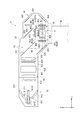
図1は、本実施形態に係るプロジェクター1を示す斜視図である。また、図2は、カバー部材22を取り外した状態のプロジェクター1を天面部2A側から見た平面図である。なお、図2においては、外装筐体2内において装置本体3を構成する光学ユニット4の配置位置を点線で示している。
本実施形態に係るプロジェクター1は、PC(Personal Computer)等の画像出力装置(図示省略)から受信される画像情報に応じた画像を形成し、当該画像をスクリーン等の被投射面上に拡大投射するものである。このプロジェクター1は、図1及び図2に示すように、外装を構成して、後述する装置本体3を内部に収容する外装筐体2を備える。
外装筐体2は、全体略直方体形状を有する合成樹脂製の筐体である。この外装筐体2は、互いに対向する天面部2A及び底面部2Bと、左右の両側面部2C,2Dと、被投射面に対してそれぞれ離間及び近接する側面部である背面部2E及び前面部2Fとを有する。すなわち、プロジェクター1は、前面部2F側が被投射面に近い位置となり、背面部2E側が被投射面から離れた位置となるように配置される。
Hereinafter, a first embodiment of the present invention will be described based on the drawings.
FIG. 1 is a perspective view showing a projector 1 according to this embodiment. FIG. 2 is a plan view of the projector 1 with the
The projector 1 according to the present embodiment forms an image according to image information received from an image output device (not shown) such as a PC (Personal Computer), and enlarges and projects the image on a projection surface such as a screen. To do. As shown in FIGS. 1 and 2, the projector 1 includes an
The
天面部2Aは、前面部2Fから背面部2Eに向かう方向の略中心位置よりも背面部2E側に位置する第1傾斜面2A1及び第2傾斜面2A2と、操作パネル2A3とを有する。
第1傾斜面2A1は、第2傾斜面2A2に対して背面部2E側に位置し、当該背面部2E側から前面部2F側に向かうに従って、底面部2Bに近接する方向に傾斜している。この第1傾斜面2A1には、後述する投射光学装置46の非球面ミラー462(図5)に向けて窪む凹部2A11が形成されている。この凹部2A11は、第1傾斜面2A1における側面部2C側に形成され、当該凹部2A11の底部分には、後述する投射光学装置46により投射される画像を通過させる第1開口部2A12が形成されている。この第1開口部2A12の形成位置は、当該投射光学装置46が有する開口部4631(図5)に対応している。
The
The first inclined surface 2A1 is located on the
第2傾斜面2A2は、第1傾斜面2A1に連接し、背面部2Eから前面部2Fに向かうに従って底面部2Bから離間する方向に傾斜している。
操作パネル2A3は、天面部2Aにおいて背面部2E側の端部から第1傾斜面2A1に至るまでの範囲内で、かつ、側面部2D側の位置に設けられている。この操作パネル2A3には、プロジェクター1を操作するための複数のキーが配設されている。
The second inclined surface 2A2 is connected to the first inclined surface 2A1, and is inclined in a direction away from the
The operation panel 2A3 is provided in a range from the end on the
天面部2Aを上側にして前面部2F側からプロジェクター1を見た場合に、左側に位置する左側面部2Cには、吸気口2C1が形成されている。この吸気口2C1の内側には、エアフィルター(図示省略)が設けられ、当該吸気口2C1及びエアフィルターを介して装置本体3を冷却する冷却空気が外装筐体2内に導入される。
左側面部2Cとは反対側の右側面部2Dには、装置本体3を冷却した空気を外装筐体2外に排出する排気口2D1(図2)が形成されている。
When the projector 1 is viewed from the
An exhaust port 2D1 (FIG. 2) is formed in the
右側面部2Dの略中央は、筐体本体21の側面に設けられたインターフェイス部23(図2)を覆い、当該筐体本体21に着脱自在に設けられるカバー部材22により形成される。このカバー部材22は、詳しい図示を省略するが、第2傾斜面2A2を含む天面部2Aの一部、底面部2Bの一部、及び、右側面部2Dの一部をそれぞれ形成する3つの側面部を有する横向きのU字状に形成されている。
なお、上記筐体本体21は、上記天面部2A、及び、各面部2C,2D,2E,2Fのそれぞれの一部を構成するアッパーケース211と、底面部2B、及び、各面部2C,2D,2E,2Fのそれぞれの一部を構成するロアーケース212とが組み合わされて構成されている。
The approximate center of the right
The
[装置本体の構成]
装置本体3は、図2に示すように、外装筐体2内に収容されている。この装置本体3は、画像を形成及び投射する光学ユニット4と、プロジェクター1の構成部品を冷却する冷却装置6(図11参照)と、を備える。この他、具体的な図示は省略したが、装置本体3は、当該装置本体3の構成部品に電力を供給する電源装置、及び、装置本体3の動作を制御する制御装置等を備える。
[Device configuration]
As shown in FIG. 2, the apparatus main body 3 is accommodated in the
[光学ユニットの構成]
図3は、光学ユニット4を示す斜視図である。また、図4は、光学ユニット4の構成を示す模式図である。
光学ユニット4は、上記制御装置による制御の下、画像情報(画像信号を含む)に応じた画像を形成して投射する光学装置である。この光学ユニット4は、図3及び図4に示すように、光源装置41(図3及び図4)及び各種装置42〜46(図4)と、光学部品用筐体47(図3及び図4)と、第2支持部材としてのレンズ支持部材48(図3)と、プリズムベース49(図3)と、を備える。
[Configuration of optical unit]
FIG. 3 is a perspective view showing the
The
なお、本実施形態では、光源装置41から出射される光の進行方向をZ方向とし、当該Z方向にそれぞれ直交し、かつ、互いに直交する方向をX方向及びY方向とする。また、Y方向は、上記底面部2Bから天面部2Aに向かう方向とし、X方向は、背面部2Eから前面部2Fに向かう方向とする。すなわち、X方向は、プロジェクター1を天面部2A側から平面視した場合に、投射光学装置46による画像の投射方向と平行な方向(詳しくは、当該画像の投射方向と同方向)となる。
In the present embodiment, the traveling direction of the light emitted from the
光源装置41は、図4に示すように、光源ランプ411、リフレクター412及び平行化レンズ413と、これらを内部に収納するハウジング414と、を有し、均一化装置42に光を出射する。
均一化装置42は、光源装置41から出射された光束の中心軸に対する直交面内の照度を均一化する。この均一化装置42は、光源装置41からの光の入射順に、第1レンズアレイ421、調光装置422、第2レンズアレイ423、偏光変換素子424及び重畳レンズ425を有する。
As shown in FIG. 4, the
The
色分離装置43は、均一化装置42から入射される光束を、赤(R)、緑(G)及び青(B)の3つの色光に分離する。この色分離装置43は、青色光を反射させて緑色光及び赤色光を透過させるダイクロイックミラー431と、当該ミラー431を透過した緑色光及び赤色光のうち、緑色光を反射させて赤色光を透過させるダイクロイックミラー432と、青色光の光路上に設けられる反射ミラー433と、を有する。
リレー装置44は、分離された赤色光の光路上に設けられる。このリレー装置44は、入射側レンズ441、リレーレンズ443及び反射ミラー442,444を有する。
The
The
電気光学装置45は、分離された各色光を変調して、画像信号に応じた画像を形成する。この電気光学装置45は、それぞれ分離された色光毎に設けられるフィールドレンズ451、入射側偏光板452、光変調装置としての液晶パネル453及び出射側偏光板454と、色合成装置としてのクロスダイクロイックプリズム455と、を有する。これらのうち、液晶パネル453(赤、緑及び青用の液晶パネルをそれぞれ453R,453G,453Bとする)は、入射される色光を、上記制御装置から入力される画像信号に基づいてそれぞれ変調する。また、クロスダイクロイックプリズム455は、各液晶パネル453R,453G,453Bにより変調された各色光(各色画像)を合成する。
なお、詳しくは後述するが、液晶パネル453、出射側偏光板454及びクロスダイクロイックプリズム455は一体化されており、これらにより画像形成装置5が構成されている。
The electro-
As will be described in detail later, the
図5は、投射光学装置46を示す断面図である。換言すると、図5は、プロジェクター1を示すXY断面図である。なお、図5においては、光学部品用筐体47等の図示を省略している。
投射光学装置46は、電気光学装置45(画像形成装置5)から入射される光(画像)を上記被投射面上に拡大投射する。この投射光学装置46は、図5に示すように、複数のレンズ461と、反射ミラーである非球面ミラー462と、これらを内部に収納する中空状の保持体463とを備える。
FIG. 5 is a sectional view showing the projection
The projection
複数のレンズ461は、例えば、ズームレンズ及びフォーカスレンズを有する。
非球面ミラー462は、回転対称でない自由曲面形状の反射面462Aを有する。この非球面ミラー462は、投射光学装置46における光路最下流において、反射面462Aが前面側斜め上方(底面部2Bに対する天面部2A側)を向くように配設される。そして、当該非球面ミラー462は、複数のレンズ461により、前面部2F側から背面部2E側に導かれた画像を前面部2F側に反射させ、斜め上方側に折り返すとともに、当該画像を広角化する。
保持体463の天面部2A側には、非球面ミラー462にて反射された画像を通過させる開口部4631が形成され、当該開口部4631には、可視光を透過させるガラス等の基板4632が嵌め込まれている。
The plurality of
The
An
光学部品用筐体47は、図3に示すように、部品収納部材471及び蓋状部材472により構成される箱状筐体であり、図4に示すように、内部に照明光軸AXが設定されている。そして、上記光源装置41及び各装置42〜44は、光学部品用筐体47内において照明光軸AXに対する所定位置に配置され、上記装置45,46は、当該照明光軸AX上の位置に配置される。このため、光源装置41が光学部品用筐体47に配置された際には、当該光源装置41から出射される光の中心軸は、照明光軸AXと一致する。
As shown in FIG. 3, the
このような光学部品用筐体47は、図2に示したように、照明光軸AXが前面部2Fに沿うように配置される。また、投射光学装置46は、当該投射光学装置46を透過する光の中心軸が左側面部2Cに沿うように配置される。換言すると、光学部品用筐体47は、照明光軸がZ方向に沿うように配置され、投射光学装置46は、当該投射光学装置46を透過する光の中心軸がX方向に沿うように配置される。すなわち、光学ユニット4は、天面部2A側から見て略L字状に構成される。
As shown in FIG. 2, the
レンズ支持部材48は、図3に示すように、投射光学装置46を支持した状態で、光学部品用筐体47と組み合わされ、底面部2Bの内面に固定される。このレンズ支持部材48は、投射光学装置46の光軸に沿って見た場合に略U字状に形成されたU字状部481を有し、当該U字状部481の底部にて投射光学装置46を支持する。この他、U字状部481には、光学部品用筐体47の端部が当接され、これらが組み合わされた状態で、ねじにより互いに固定される。更に、U字状部481において投射光学装置46への光の入射側の端面には、後述するプリズムベース49が固定される。
As shown in FIG. 3, the
図6は、緑色光及び赤色光の入射側から見た画像形成装置5を示す斜視図である。また、図7は、光出射側から見た画像形成装置5を示す斜視図である。図8は、天面部2A側から見た画像形成装置5を示す平面図である。
画像形成装置5は、図6〜図8に示すように、上記3つの液晶パネル453(453R,453G,453B)、3つの出射側偏光板454、及び、クロスダイクロイックプリズム(以下、プリズムと略す場合がある)455と、を備える他、それぞれ本発明の取付部材としての第1保持部材51及び第2保持部材52を備える。そして、画像形成装置5は、各保持部材51,52により、各液晶パネル453、各出射側偏光板454及びプリズム455が一体化された状態で、後述するプリズムベース49により、レンズ支持部材48に固定される。
FIG. 6 is a perspective view showing the
As shown in FIGS. 6 to 8, the
以下、画像形成装置5の構成について説明する。
液晶パネル453は、入射される色光を画像情報に応じて変調して、当該色光に応じた画像を形成するパネル本体4531と、当該パネル本体4531から延出するフレキシブルプリント基板4532と、パネル本体4531をそれぞれの光入射側及び光出射側から挟む入射側保持枠4533及び出射側保持枠4534と、を有する。
これらのうち、入射側保持枠4533の略中央には、入射される色光を透過させて、内部に収納されるパネル本体4531に当該色光を入射させる開口部4533Aが形成されている。同様に、出射側保持枠4534の略中央には、図示を省略するが、当該パネル本体4531により変調された色光を透過させる開口部が形成されている。
Hereinafter, the configuration of the
The
Among these, an
プリズム455は、直角三角柱状を有する4つのプリズムを貼り合せた略直方体形状を有する。このプリズム455は、図7に示すように、上記各液晶パネル453及び出射側偏光板454を通過した赤(R)、緑(G)及び青(B)の各色光がそれぞれ入射される3つの光入射面4550(赤、緑及び青用の光入射面をそれぞれ455R,455G,455Bとする)を有する。これら光入射面4550(455R,455G,455B)に対向するように、第1保持部材51及び第2保持部材52により、対応する液晶パネル453(453R,453G,453B)及び出射側偏光板454が保持される。
The
このようなプリズム455において、上記4つのプリズムを互いに貼り合せた界面には、2つの誘電体多層膜が形成されている。これら誘電体多層膜は、光入射面455Gに入射された緑色光を透過させ、光入射面455R及び光入射面455Bに入射された赤色光及び青色光をそれぞれ緑色光が透過する方向に反射させる。このようにして合成された各色光は、合成光として光入射面455Gとは反対側に位置する光出射面455Aから、上記投射光学装置46に出射される。
また、プリズム455において、各光入射面455R,455G,455B及び光出射面455Aと交差する一対の側面のうち、底面部2B側の側面455T(図9)は、後述するプリズムベース49の支持部493に接着固定される。これにより、プリズム455は、プリズムベース49、ひいては、上記レンズ支持部材48に支持される。
In such a
In the
第1保持部材51及び第2保持部材52は、液晶パネル453と、対応する光入射面4550との間にそれぞれ配置され、当該液晶パネル453を光入射面4550に固定する。すなわち、第1保持部材51及び第2保持部材52は、分離された色光毎に設けられ、本実施形態では、それぞれ3つ設けられる。
第1保持部材51は、第2保持部材52に対して光出射側に位置し、光入射面4550に固定される。このような第1保持部材51は、板状の金属製部材であり、詳しい図示を省略するが、当該第1保持部材51の略中央には、当該光入射面4550との間に隙間が形成されるように出射側偏光板454が取り付けられる取付部が設けられ、また、当該出射側偏光板454を透過した光を光入射面に入射させる開口部が形成されている。
更に、第1保持部材51の四隅近傍には、図7及び図8に示すように、光入射側に突出する突出部511がそれぞれ設けられている。
The first holding
The first holding
Further, in the vicinity of the four corners of the first holding
第2保持部材52は、図6〜図8に示すように、液晶パネル453を保持した状態で、第1保持部材51により支持され、これにより、液晶パネル453が、対応する光入射面4550に保持される。
この第2保持部材52は、板状の金属製部材であり、当該第2保持部材52における光入射側の面は、液晶パネル453が取り付けられる取付面である。この取付面の略中央には、液晶パネル453を透過した光が通過する開口部(図示省略)が形成されている。
また、第2保持部材52の四隅近傍には、孔部(図示省略)がそれぞれ形成されている。これら孔部に上記突出部511が挿入された状態で、液晶パネル453の位置調整が治具(図示省略)を用いて行われる。そして、各孔部内に注入された紫外線硬化接着剤等の接着剤を硬化させることで、第2保持部材52が第1保持部材51に固定される。これにより、各液晶パネル453及び各出射側偏光板454がプリズム455に固定され、これらが一体化する。
As shown in FIGS. 6 to 8, the second holding
The second holding
In addition, holes (not shown) are formed in the vicinity of the four corners of the second holding
[プリズムベースの構成]
図9は、画像形成装置5を支持した状態のプリズムベース49を示す断面図である。詳述すると、図9は、当該状態のプリズムベース49のXY断面を示す図である。
プリズムベース49は、本発明の第1支持部材に相当し、図5に示すように、上記プリズム455の側面455T、ひいては、上記画像形成装置5を支持するとともに、レンズ支持部材48に取り付けられる。このプリズムベース49は、少なくともアルミ合金を含む金属を溶融し、金型に当該溶融した金属を圧入するダイカストにより成形された一体成形品である。なお、プリズムベース49は、他の材料で形成されていてもよい。
このようなプリズムベース49は、図7及び図9に示すように、第2支持部材としてのレンズ支持部材48のU字状部481におけるY方向とは反対側の端部に接続される接続部491と、当該接続部491からX方向とは反対方向(すなわち、投射光学装置46への光入射方向の反対方向)に延出する延出部492と、当該延出部492の先端部に設けられる支持部493とを有する。
[Configuration of prism base]
FIG. 9 is a cross-sectional view showing the
The
As shown in FIGS. 7 and 9, such a
接続部491は、図6に示すように、上記U字状部481の端部に接続される接続面4911を有し、当該接続面4911は、当該U字状部481に向けて突出する位置決めピン4912と、当該U字状部481に固定されるねじ(図示省略)が挿通する3つの孔部4913とを有する。
延出部492は、図9に示すように、プロジェクター1の重量を軽量化するため、中央部分に凹部4921を有する半円筒形状に形成されている。この延出部492は、レンズ支持部材48に上記接続部491が接続された際に、当該接続部491からX方向とは反対側に延出した後、Y方向に向かって屈曲する断面略L字状に形成されている。換言すると、この延出部492は、後述するダクト62の送出口(例えば、送出口62G2)からの冷却空気の送出方向に対して略直交する方向に延出する。そして、当該延出部492におけるY方向とは反対側の面は、X方向及びY方向にそれぞれ傾斜する傾斜面494とされている。
支持部493は、XZ平面に沿い、上記側面455Tを支持する支持面4931を有する。この支持面4931の略中央には、膨出部4932が形成されており、当該膨出部4932にて、支持されるプリズム455の姿勢を調整可能である。
As shown in FIG. 6, the connecting
As shown in FIG. 9, the extending
The
[冷却装置の構成]
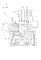
図10は、ロアーケース212内部を示す平面図である。換言すると、図10は、ロアーケース212内に配置される投射光学装置46、画像形成装置5及び冷却装置6の位置を示す平面図である。
冷却装置6は、上記のように、プロジェクター1の構成部品を冷却する。この冷却装置6は、図10に示すように、画像形成装置5を冷却する冷却空気を吐出する3つのファン61と、当該各ファン61から吐出された冷却空気を各液晶パネル453に導くダクト62と、を備える。この他、冷却装置6は、図示を省略するが、吸気口2C1(図1参照)を介して外部の空気を外装筐体2内に取り込む吸気ファン、及び、プロジェクター1の構成部品の冷却に供されて熱を帯びた空気を、排気口2D1(図2参照)を介して外装筐体2外に排出する排気ファンを備える。
[Configuration of cooling device]
FIG. 10 is a plan view showing the inside of the
The
[ファンの構成]
3つのファン61のうち、液晶パネル453Rを冷却する空気を送風するファン61Rは、投射光学装置46と左側面部2Cの内面との間に配置される。また、液晶パネル453Gを冷却する空気を送風するファン61Gは、天面部2A側から見た場合に、光学部品用筐体47の外側で、かつ、左側面部2Cと前面部2Fとの角隅部近傍に配置される。更に、液晶パネル453Bを冷却する空気を送風するファン61Bは、天面部2A側から見た場合に、光学部品用筐体47の外側で、かつ、前面部2F側の位置に配置される。
これらファン61R,61G,61Bのうち、ファン61R,61Bは、吸気口が形成された吸気面が底面部2Bの内面2B1から起立するように配置される。一方、ファン61Gは、吸気面が内面2B1に沿うように配置される。
そして、これらファン61R,61G,61Bは、それぞれ、ダクト62において対応する導入口62R1,62G1,62B1に、外装筐体2内に導入された空気を吸引して送出する。
[Fan configuration]
Of the three
Among these
The
[ダクトの構成]
図11は、冷却装置6を天面部2A側から見た平面図である。
ダクト62は、上記のように、各ファン61から送出された空気を、各液晶パネル453に導くものであり、画像形成装置5及び光学部品用筐体47と内面2B1との間に配置される。すなわち、ダクト62は、画像形成装置5に対して底面部2B側(Y方向とは反対側)に配置される。このようなダクト62は、ファン61Rから送出された空気を液晶パネル453Rに導くダクト部62Rと、ファン61Gから送出された空気を液晶パネル453Gに導くダクト部62Gと、ファン61Bから送出された空気を液晶パネル453Bに導くとともに、上記偏光変換素子424に導くダクト部62Bと、規制部材8とを有し、これらが一体的に形成された構成を有する。
[Duct structure]
FIG. 11 is a plan view of the
As described above, the
ダクト部62Rは、天面部2A側から見た場合に、円弧状に略90°屈曲した形状に形成されている。このダクト部62Rは、一端側にファン61Rの吐出口と接続される導入口62R1を有し、他端側に内部を流通した空気を液晶パネル453Rに向けて送出する送出口62R2を有する。
なお、ダクト部62Rは、当該ダクト部62Rの終端側(送出口62R2が位置する端部側)に向かうに従って、液晶パネル453Rに入射される赤色光の中心軸に沿うように形成及び配置されている。このため、ダクト部62R内を流通して、送出口62R2から送出される空気の流通方向は、液晶パネル453Rの中央を通り、かつ、当該液晶パネル453Rの幅方向の中心線(パネル本体4531の画像形成領域における短手方向に沿う中心線)に沿う方向である。
The
Note that the
ダクト部62Gは、天面部2A側から見た場合に、液晶パネル453Gに入射される緑色光の中心軸に対して直交する方向に延出している。具体的に、ダクト部62Gは、液晶パネル453Rに入射される赤色光の中心軸に沿って、液晶パネル453Gの下方(底面部2B側)にまで延出している。
このダクト部62Gは、一端側にファン61Gの吐出口と接続される導入口62G1を有し、他端側に内部を流通した空気を液晶パネル453Gに向けて送出する送出口62G2を有する。この送出口62G2は、液晶パネル453G、及び、当該液晶パネル453Gを光入射面455Gに保持させる上記第2保持部材52のそれぞれの底面部2B側に位置している。そして、この送出口62G2において、光入射側の端縁と光出射側の端縁との間の寸法は、液晶パネル453Gの同方向の寸法より大きく形成されており、当該送出口62G2の形成範囲内に、液晶パネル453Gにおける光入射側の端面及び光出射側の端面が位置するように、送出口62G2は形成されている。
The
なお、送出口62G2から送出された冷却空気は、液晶パネル453Gの下方から上方に向けて送出される。この際、当該冷却空気は、ダクト部62G内を液晶パネル453Gの幅方向の一方側(液晶パネル453R側)から他方側(液晶パネル453B側)に向けて流通したことから、送出口62G2から液晶パネル453Rに向けて送出された空気は、当該一方側の下方から、他方側の上方に向けて流通する。すなわち、送出口62G2から送出された空気は、液晶パネル453の光入射側から見て、当該液晶パネル453Rの光入射側及び光出射側を斜めに流通する。
The cooling air sent from the outlet 62G2 is sent upward from the lower side of the
ダクト部62Bは、ファン61Bの吐出口と接続される導入口62B1を一端側に有し、液晶パネル453Bに内部を流通した冷却空気を送出する送出口62B2を他端側に有するダクト本体62B0を備える。
このダクト本体62B0は、ファン61Bから液晶パネル453Bの下方(底面部2B側)の位置まで延出しており、略中央部分には、天面部2A側から見て鈍角に屈曲した分岐部62B4が形成されている。
この分岐部62B4からダクト本体62B0の終端までの部位は、天面部2A側から見て、液晶パネル453Bに入射される青色光の中心軸に直交する方向に延出している。すなわち、当該部位は、液晶パネル453Gに入射される緑色光の中心軸に沿うように、液晶パネル453Bにおける幅方向の一方側(液晶パネル453G側)から他方側(液晶パネル453Gとは反対側であり、投射光学装置46の配置側)に向けて延出している。このため、送出口62B2から送出される空気は、液晶パネル453Gにおける上記一方側の下方から、他方側の上方に向けて流通する。このように、送出口62B2から送出された空気が流通するため、当該送出口62B2は、液晶パネル453Bの下方において上記一方側、すなわち、液晶パネル453Gの配置側に偏って形成されている。
The
The duct main body 62B0 extends from the
A portion from the branch portion 62B4 to the end of the duct main body 62B0 extends in a direction orthogonal to the central axis of the blue light incident on the
ダクト部62Bは、上記分岐部62B4から分岐して、上記偏光変換素子424に向かって直線状に延出する分岐ダクト部62B5を有し、当該分岐ダクト部62B5の終端は、上記光学部品用筐体47に接続される。この終端には、送出口62B6が形成されている。そして、分岐ダクト部62B5内を流通した冷却空気は、流通方向が上方(天面部2A側)に変更され、当該空気は、送出口62B6を介して偏光変換素子424(図4参照)に送出される。
The
更に、ダクト部62Bは、上記分岐部62B4から送出口62B2に至るまでの範囲内に、天面部2A側から見てダクト本体62B0から略直角に分岐して、ダクト部62G側に延出する他の分岐ダクト部62B8を有する。
この分岐ダクト部62B8は、内部を流通した空気を、終端部分に形成された送出口62B9を介して液晶パネル453Gの光入射側に送出して、ダクト部62G内を流通して液晶パネル453Gに向けて送出された空気が、当該液晶パネル453Gから離れる方向に流通することを抑制する空気の流れを形成する。
このような空気が送出される送出口62B9は、送出口62G2より液晶パネル453Gにおける上記他端側(液晶パネル453B側)に位置している。この他、送出口62B9の中央位置は、送出口62G2の中央位置より液晶パネル453Gに対して光入射側に位置している。
Further, the
This branching duct part 62B8 sends the air flowing through the inside to the light incident side of the
The outlet 62B9 through which such air is sent is located on the other end side (
[規制部材の構成]
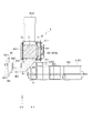
図12は、画像形成装置5、プリズムベース49及びダクト62を拡大して示す断面図である。換言すると、図12は、画像形成装置5及びプリズムベース49と、ダクト62との位置関係を示す図である。
規制部材8は、液晶パネル453及び上記保持部材51,52のいずれかと、ダクト62とが衝突することを規制する部材であり、本実施形態では、ダクト62と一体的に形成されている。この規制部材8は、図11に示すように、各ダクト部62R,62G,62Bの終端部分により囲まれた位置に配置されており、プリズムベース49に対して底面部2B側に位置している。
このような規制部材8は、図12に示すように、レンズ支持部材48との支持位置を中心として投射光学装置46がY方向及びY方向とは反対方向に揺動した場合に、プリズムベース49の傾斜面494に当接する傾斜面、すなわち、傾斜面494と略平行な規制面81を有する。これら傾斜面494と規制面81とは、これらの間にわずかな隙間を開けた状態でロアーケース212に組み込まれる。
[Configuration of restriction members]
FIG. 12 is an enlarged sectional view showing the
The regulating
As shown in FIG. 12, such a regulating
具体的に、本実施形態においては、ダクト62と画像形成装置5との間で、最も距離が短いのは、ダクト部62Gと液晶パネル453Gを保持する第2保持部材52との間の距離である。
このような距離では、使用者の不注意等により、プロジェクター1が落下した場合、上記のように、投射光学装置46が、レンズ支持部材48との支持位置を中心としてY方向及びY方向とは反対方向に揺動し、ひいては、レンズ支持部材48及びプリズムベース49を介して投射光学装置46に接続された画像形成装置5も同方向に揺動する。この際、当該画像形成装置5は、上記支持位置から離れた位置に配置されているため、当該同方向に比較的大きく揺動し、第2保持部材52がダクト部62Gと衝突する可能性がある。このような場合、光入射面455Gに対する液晶パネル453Gの位置がずれ、ひいては、投射光学装置46により、液晶パネル453R,453Bを透過した光が出射される位置と、液晶パネル453Gを透過した光が出射される位置とがずれて、画素ずれが生じる可能性がある。
Specifically, in the present embodiment, the shortest distance between the
At such a distance, when the projector 1 is dropped due to carelessness of the user or the like, the Y direction and the Y direction of the projection
これに対し、上記規制面81は、上記のように投射光学装置46が揺動する際にプリズムベース49が規制部材8に近接する方向において、ダクト部62Gと第2保持部材52との間の距離より短い距離、傾斜面494から離間した位置に配置されている。このため、上記のように、投射光学装置46が揺動して、第2保持部材52がダクト部62Gに近接する方向に移動する場合でも、プリズムベース49と規制部材8とが先に接触することにより、第2保持部材52がダクト部62Gに衝突することを回避できる。これにより、液晶パネル453Gとダクト部62Gとの衝突だけでなく、液晶パネル453Rとダクト部62Rとの衝突、及び、液晶パネル453Bとダクト部62Bとの衝突を回避できる。従って、上記画素ずれの発生を抑制できる。更に、規制面81と傾斜面494との距離が比較的短くなるため、これらが接触した場合の衝撃も小さくできる。
On the other hand, the
以上説明した本実施形態に係るプロジェクター1によれば、以下の効果がある。
上記のように、プロジェクター1は、ダクト62による冷却空気の送出方向(Y方向)に交差する方向(X方向と逆方向)に延出して、プリズム455を支持するプリズムベース49と、プリズム455がダクト62に近接する方向である底面部2B側に移動される際に、プリズムベース49が当接されて、複数の液晶パネル453(453R,453G,453B)の少なくともいずれかがダクト62に衝突することを規制する規制部材8を備えているので、プロジェクター1に落下等の衝撃が加わって、プリズム455及び液晶パネル453が底面部2B側に移動される際に、プリズムベース49と規制部材8とが互いに当接することで、液晶パネル453及び液晶パネル453を保持する第2保持部材52とダクト62との衝突が規制される。これによれば、液晶パネル453の冷却効率を考慮して、当該液晶パネル453に対してダクト62(ダクト62の送出口62R2,62G2,62B2)を近接配置した場合でも、液晶パネル453又は第2保持部材52がダクト62に衝突して、プリズム455に対する液晶パネル453の位置が変更されることを抑制できる。従って、それぞれの液晶パネル453R,453G,453Bから入射されて光入射面4550から出射される各色光の位置がずれることを抑制できるので、画素ずれの発生を抑制できる。
The projector 1 according to the present embodiment described above has the following effects.
As described above, the projector 1 includes a
プリズムベース49が投射光学装置46を支持するレンズ支持部材48に固定され、当該投射光学装置46から延出しているので、これらプリズムベース49及びレンズ支持部材48により、投射光学装置46とプリズム455とを一体化できる。従って、これらの位置を良好に維持できる。
一方、プロジェクター1に上記衝撃が加わった場合には、レンズ支持部材48による支持位置を中心として、比較的大きな投射光学装置46が揺動する。この際、プリズムベース49がレンズ支持部材48から延出して、投射光学装置46の一端側にプリズム455及び液晶パネル453が一体化されて設けられていることにより、これらプリズム455及び液晶パネル453の揺動範囲は大きくなり、ダクト62に複数の液晶パネル453R,453G,453Bのいずれか(特に、投射光学装置46の光軸上に位置する液晶パネル453G)がダクト62に衝突しやすくなる。
これに対し、本実施形態では、プリズムベース49と規制部材8とが当接して、液晶パネル453とダクト62との衝突を規制できるので、上記構成であっても、液晶パネル453に位置ずれが生じることを抑制でき、ひいては、画素ずれの発生を抑制できる。
Since the
On the other hand, when the impact is applied to the projector 1, the relatively large projection
On the other hand, in the present embodiment, the
上記のように、プリズムベース49の延出部492(傾斜面494)と規制部材8(規制面81)との間の距離は、ダクト62と、複数の液晶パネル453(453R,453G,453B)のいずれか、及び、当該液晶パネル453(453R,453G,453B)を対応するプリズム455の光入射面4550に取り付ける第2保持部材52のうちダクト62に近い方との間の距離より短いので、プロジェクター1に上記衝撃が加わって、画像形成装置5が揺動した場合でも、液晶パネル453及び第2保持部材52のいずれかがダクト62に衝突するより前に、プリズムベース49と規制部材8とを当接させることができる。従って、光入射面4550に対する液晶パネル453の位置が変更されて画素ずれが発生することを確実に抑制できる。
As described above, the distance between the extending portion 492 (inclined surface 494) of the
プリズムベース49は、規制部材8に対向する対向面である傾斜面494を有し、規制部材8は、当該傾斜面494と略平行な規制面81を有し、プリズム455及び液晶パネル453がダクト62側に揺動する場合には、傾斜面494と規制面81とが、面接触する。これによれば、プリズムベース49と規制部材8との当接によって生じる衝撃を面で分散することができるので、これらが点で当接する場合に比べて、プリズムベース49と規制部材8との当接の衝撃を緩和できる。従って、プリズム455及び液晶パネル453に当該衝撃を伝達しにくくすることができ、液晶パネル453の位置が変更されて画素ずれが発生することをより確実に抑制することができる。
The
規制部材8がダクト62に設けられているので、規制部材8を別部材として別途配置する必要が無く、上記効果を奏するプロジェクター1の構成を簡略化できる。また、これにより、プロジェクター1の製造工程を簡略化でき、生産性の向上が可能となる。
Since the regulating
プリズムベース49がダイカストにより形成されているので、当該プリズムベース49の強度を高めることができる。これにより、規制部材8がプリズムベース49に当接したとしても、プリズムベース49が変形することを抑制できるため、確実にダクト62と、液晶パネル453又は第2保持部材52との衝突を抑制できる。また、プリズムベース49の経年劣化が生じにくいので、長期にわたって、ダクト62と液晶パネル453との衝突を抑制できる。従って、液晶パネル453の位置が変えられることによる画素ずれの発生を長期に渡って、確実に抑制できる。
Since the
[第2実施形態]
次に、本発明の第2実施形態について説明する。
本実施形態に係るプロジェクターは、上記プロジェクター1と同様の構成を有するが、規制部材8の設けられる位置がプロジェクター1と相違する。なお、以下の説明では、既に説明した部分と同一又は略同一である部分については、同一の符号を付して説明を省略する。
[Second Embodiment]
Next, a second embodiment of the present invention will be described.
The projector according to the present embodiment has the same configuration as that of the projector 1, but the position where the regulating
図13は、本発明の第2実施形態に係るプロジェクター1Aの断面図である。
本実施形態に係るプロジェクター1Aは、規制部材8が一体的に形成されたダクト62に代えて、規制部材8が設けられていないダクト62Aと規制部材8Aとを有する他は、上記プロジェクター1と同様の構成を有する。
これらのうち、規制部材8Aは、ロアーケース212の底面(底面部2Bの内面2B1)と一体的に形成されている。この規制部材8Aは、図13に示すように、各ダクト部62R,62G,62Bの終端部分により囲まれた位置で、かつ、投射光学装置46が移動して画像形成装置5がダクト62A側に移動する方向に、上記内面2B1から突出しており、プリズムベース49の底面部2B側に位置している。このような規制部材8Aは、上記のように投射光学装置46が揺動する場合に、プリズムベース49の傾斜面494に当接する傾斜面、すなわち、当該傾斜面494と略平行な規制面81Aを有する。これら傾斜面494と規制面81Aとは、これらの間に、傾斜面494と上記規制面81との間の隙間と同様の隙間を開けた状態でロアーケース212に組み込まれる。
FIG. 13 is a sectional view of a
The
Among these, the regulating
以上説明した本実施形態に係るプロジェクター1Aによれば、上記プロジェクター1と同様の効果がある他、以下の効果がある。
本実施形態では、規制部材8Aが上記内面2B1と一体的に形成されているので、規制部材8Aを別部材として別途配置する必要が無いので、上記効果を奏するプロジェクター1Aの構成を簡略化できる。また、これにより、プロジェクターの製造工程を簡略化でき、生産性の向上が可能となる。
The
In the present embodiment, since the regulating
[第3実施形態]
次に、本発明の第3実施形態について説明する。
本実施形態に係るプロジェクターは、上記プロジェクター1と同様の構成を有するが、規制部材の設けられる位置がプロジェクター1と相違する。なお、以下の説明では、既に説明した部分と同一又は略同一である部分については、同一の符号を付して説明を省略する。
[Third Embodiment]
Next, a third embodiment of the present invention will be described.
The projector according to the present embodiment has the same configuration as that of the projector 1, but the position where the regulating member is provided is different from the projector 1. In the following description, parts that are the same as or substantially the same as those already described are assigned the same reference numerals and description thereof is omitted.
図14は、本発明の第3実施形態に係るプロジェクター1Bの断面図である。
本実施形態に係るプロジェクター1Bは、規制部材8が一体的に形成されたダクト62に代えて、規制部材8が設けられていないダクト62Aを有し、プリズムベース49に代えてプリズムベース49Bを有する他は、上記プロジェクター1Aと同様の構成を有する。
プリズムベース49Bは、図14に示すように、傾斜面494の中腹部から、ロアーケース212の底面(すなわち、底面部2Bの内面2B1)側に向けて、延出する延出部495を有する以外は、プリズムベース49Aと同様の構成を有する。この延出部495の底面部2B側の端部には、ロアーケース212の内面2B1に対向する対向面495Aが位置している。本実施形態では、上記のように投射光学装置46が揺動する場合に、延出部495の対向面495Aがロアーケース212の内面2B1の一部である規制部2B2に面接触する。すなわち、ロアーケース212の内面2B1のうち、延出部495の対向面495Aが当接する部分(規制部2B2)が本発明の規制部材として機能する。このプリズムベース49の対向面495Aと、当該対向面495Aに対向する規制部2B2の面とは、略平行に設けられており、プリズムベース49は、当該プリズムベース49の対向面495Aと規制部2B2との間に、上記傾斜面494と上記規制面81との間の隙間と同様の隙間を開けた状態でロアーケース212に組み込まれる。
FIG. 14 is a cross-sectional view of a
The projector 1 </ b> B according to the present embodiment has a
As shown in FIG. 14, the prism base 49B has an extending
以上説明した本実施形態に係るプロジェクター1Bによれば、上記プロジェクター1と同様の効果がある他、以下の効果がある。
本実施形態では、ロアーケース212の内面2B1のうち、延出部495の対向面495Aが当接する部分(規制部2B2)が本発明の規制部材として機能するので、規制部材を別途配置する必要が無いので、上記効果を奏するプロジェクター1Bの構成を簡略化できる。また、これにより、プロジェクターの製造工程を簡略化でき、生産性の向上が可能となる。
また、プリズムベース49の対向面495Aがロアーケース212の規制部2B2における上記面と略平行であり、かつ、プリズム455の底面部2B側の面に対して平行であるため、プリズムベース49の対向面495Aと規制部2B2とが当接する際にいずれかの方向(例えば、X方向及びZ方向)にずれることを抑制できる。すなわち、プリズム455及び液晶パネル453に当該衝撃をより伝達しにくくすることができ、液晶パネル453の位置が変更されて画素ずれが発生することをより確実に抑制できる。
The
In the present embodiment, of the inner surface 2B1 of the
Further, since the facing
[実施形態の変形]
本発明は、上記実施形態に限定されるものではなく、本発明の目的を達成できる範囲での変形、改良等は本発明に含まれるものである。
上記第1及び第2実施形態では、規制部材8,8Aは、傾斜面494と略平行で、かつ、平面状に形成された規制面81,81Aを有するとしたが、これに限らず、プリズムベース49による衝撃を緩和する形状であれば、規制面の形状は、どのような形状であってもよい。例えば、規制部材は、プリズムベース49を包み込む形状、プリズムベース49の傾斜面494に対して凸部分を有さない形状、その他、プリズムベース49の延出部492の形状と同一の形状であってもよい。
また、規制部材8,8Aの規制面81,81A及びプリズムベース49の傾斜面494の少なくとも一方を梨地状に形成し、接触した際の摩擦力を高めるようにしてもよい。
更に、規制部材8,8Aの規制面81,81A及びプリズムベース49の傾斜面の少なくとも一方に弾性部材を取り付けるようにしてもよいし、規制部材8,8Aを弾性部材、例えば、シリコーンゴム等で形成してもよい。
[Modification of Embodiment]
The present invention is not limited to the above-described embodiment, and modifications, improvements, and the like within the scope that can achieve the object of the present invention are included in the present invention.
In the first and second embodiments, the restricting
Further, at least one of the regulating surfaces 81 and 81A of the regulating
Further, an elastic member may be attached to at least one of the restricting
上記各実施形態では、プリズムベース49は、投射光学装置46を支持するレンズ支持部材48に取り付けられ、当該投射光学装置46に入射される光の進行方向(X方向)とは反対方向に延出しているとした。しかしながら、本発明はこれに限らない。例えば、プリズムベース49の取付位置は、外装筐体2の内面でもよく、他の箇所であってもよい。すなわち、各液晶パネル453が取り付けられたプリズム455を適切な位置に配置できれば、プリズムベース49の設置位置は適宜変更可能である。
In each of the above embodiments, the
上記各実施形態では、光変調装置としての液晶パネル453(453G)とダクト62との間の距離より、取付部材としての第2保持部材52とダクト62との間の距離の方が短い構成とした。しかしながら、本発明はこれに限らない。例えば、液晶パネル453とダクト62との間の距離が、第2保持部材52とダクト62との間より短い場合には、当該距離より、延出部492と規制部材8,8A及び規制部2B2のそれぞれとの間の距離を短くすればよい。
In each of the above embodiments, the distance between the second holding
上記各実施形態では、傾斜面494は、底面部2B側及び前面部2F側(すなわち、投射光学装置46への光の入射方向(X方向)とは反対方向)を向くように傾斜しているとした。しかしながら、本発明はこれに限らない。すなわち、底面部2B側及び背面部2E側(すなわち、当該光の入射方向)を向くように傾斜していてもよい。また、画像形成装置5がダクト62,62A側に移動する際に、プリズムベース及び規制部材(規制部)において互いに対向する対向面同士が面接触すれば、当該各対向面は傾斜していなくてもよい。更に、プリズムベースと規制部材(規制部)とが点接触する構成であってもよい。
In each of the embodiments described above, the
上記第1実施形態では、規制部材8は、ダクト62に設けられるとし、上記第2実施形態では、規制部材8Aは、ロアーケース212に設けられるとし、上記第3実施形態では、規制部材としての規制部2B2は、プリズムベース49から延出した延出部495の対向面495Aが当接されるロアーケース212の内面2B1の一部とした。しかしながら、本発明はこれに限らない。すなわち、液晶パネル453及び取付部材(第1保持部材51及び第2保持部材52)の少なくともいずれかとダクト62との衝突を抑制できれば、規制部材の位置及び構成は問わない。
In the first embodiment, the
上記各実施形態では、各液晶パネル453に冷却空気を送風する冷却装置は、3つのファン61と、これら各ファン61と接続されるダクト62とを有し、当該ダクト62は、液晶パネル453に対して底面部2B側に配置されるとした。また、プリズムベース49は、当該液晶パネル453が取り付けられるプリズム455に対して底面部2B側に配置されるとした。しかしながら、本発明は、これに限らない。すなわち、これらダクト62及びプリズムベース49は、液晶パネル453及びプリズム455に対して天面部2A側に位置していてもよい。また、ファン61の配置及び数、並びに、ダクト62の構成も、適宜変更可能である。
In each of the above embodiments, the cooling device that blows cooling air to each
上記各実施形態では、光源ランプ411及びリフレクター412を有する光源装置41を採用したが、本発明はこれに限らない。例えば、光源ランプ411に代えて、LED(Light Emitting Diode)及びLD(Laser Diode)等の固体光源を採用してもよい。
上記各実施形態では、投射光学装置46は、画像形成装置5から入射される画像が透過する複数のレンズ461と、当該画像を折り返して反射させる非球面ミラー462と、これらを内部に収納する保持体463とを備える構成としたが、本発明はこれに限らない。すなわち、反射ミラーである非球面ミラー462は無くてもよい。
In each said embodiment, although the
In each of the above embodiments, the projection
上記各実施形態では、プロジェクター1は、光変調装置として3つの液晶パネル453(453R,453G,453B)を備えるとしたが、本発明はこれに限らない。すなわち、2つ以下、或いは、4つ以上の液晶パネルを用いたプロジェクターにも、本発明を適用可能である。
上記各実施形態では、光学ユニット4は略L字状に構成されていたが、本発明はこれに限らない。例えば、略U字状に構成された光学ユニットを採用してもよい。
上記実施形態では、光束入射面と光束射出面とが異なる透過型の液晶パネル453を用いていたが、光入射面と光射出面とが同一となる反射型の液晶パネルを用いてもよい。
In each of the embodiments described above, the projector 1 includes the three liquid crystal panels 453 (453R, 453G, and 453B) as the light modulation device, but the present invention is not limited to this. That is, the present invention can also be applied to a projector using two or less or four or more liquid crystal panels.
In each said embodiment, although the
In the above-described embodiment, the transmissive
上記各実施形態では、光変調装置として液晶パネル453を用いていたが、入射光束を変調して画像情報に応じた画像を形成可能な光変調装置であれば、マイクロミラー表示素子等を利用したものなど、液晶以外の光変調装置を用いてもよい。
上記各実施形態では、画像の投射方向と、当該画像の観察方向とが略同じであるフロントタイプのプロジェクター1を例示したが、本発明はこれに限らない。例えば、投射方向と観察方向とがそれぞれ反対方向となるリアタイプのプロジェクターにも適用できる。
In each of the above embodiments, the
In each of the above embodiments, the front type projector 1 in which the image projection direction and the image observation direction are substantially the same is illustrated, but the present invention is not limited to this. For example, the present invention can be applied to a rear type projector in which the projection direction and the observation direction are opposite directions.
1,1A,1B…プロジェクター、2…外装筐体、8,8A…規制部材、41…光源装置、46…投射光学装置、48…レンズ支持部材(第2支持部材)、49…プリズムベース(第1支持部材)、51…第1保持部材(取付部材)、52…第2保持部材(取付部材)、62…ダクト、81,81A…規制面、2B2…規制部(規制部材)、453…液晶パネル(光変調装置)、455…プリズム(色合成装置)、455A…光出射面、494…傾斜面(対向面)、495A…対向面、4550…光入射面。
DESCRIPTION OF
Claims (6)
前記光源装置から出射された複数の色光を色光毎にそれぞれ変調する複数の光変調装置と、
前記複数の光変調装置により変調された前記複数の色光がそれぞれ入射される複数の光入射面、及び、入射された前記複数の色光を合成した合成光を出射する光出射面を有する色合成装置と、
前記色合成装置により形成された画像を投射する投射光学装置と、
前記複数の光変調装置のそれぞれを、前記複数の光入射面のうち、対応する光入射面に取り付ける取付部材と、
前記色合成装置における前記複数の光入射面及び前記光出射面に交差する一対の端面のうちの一方側に位置し、前記複数の光変調装置の少なくとも1つに冷却空気を送出するダクトと、
前記ダクトによる前記冷却空気の送出方向に交差する方向に延出して、前記色合成装置を支持する第1支持部材と、
前記色合成装置が前記ダクトに近接する方向に移動される際に、前記第1支持部材が当接されて、前記複数の光変調装置の少なくともいずれかが前記ダクトに衝突することを規制する規制部材と、を備えることを特徴とするプロジェクター。 A light source device;
A plurality of light modulation devices that respectively modulate a plurality of color lights emitted from the light source device for each color light; and
A color combining device having a plurality of light incident surfaces on which the plurality of color lights modulated by the plurality of light modulation devices respectively enter, and a light emitting surface for emitting combined light obtained by combining the plurality of incident color lights. When,
A projection optical device for projecting an image formed by the color synthesis device;
A mounting member for attaching each of the plurality of light modulation devices to a corresponding light incident surface among the plurality of light incident surfaces;
A duct that is located on one side of a pair of end surfaces intersecting with the plurality of light incident surfaces and the light emitting surface in the color composition device, and that sends cooling air to at least one of the plurality of light modulation devices;
A first support member that extends in a direction that intersects the direction in which the cooling air is sent by the duct and supports the color composition device;
Regulation that restricts at least one of the plurality of light modulation devices from colliding with the duct when the color composition device is moved in the direction of approaching the duct and the first support member is brought into contact therewith And a member.
前記投射光学装置を支持する第2支持部材を備え、
前記第1支持部材は、前記第2支持部材から前記投射光学装置への光入射方向とは反対方向に延出して、前記色合成装置を支持することを特徴とするプロジェクター。 The projector according to claim 1.
A second support member for supporting the projection optical device;
The first support member extends in a direction opposite to a light incident direction from the second support member to the projection optical device to support the color composition device.
前記第1支持部材の延出部と前記規制部材との間の距離は、前記ダクトと、前記複数の光変調装置のいずれか、及び、当該光変調装置を対応する前記光入射面に取り付ける前記取付部材のうち前記ダクトに近い方との間の距離より短いことを特徴とするプロジェクター。 The projector according to claim 1 or 2,
The distance between the extending portion of the first support member and the regulating member is the duct, one of the plurality of light modulation devices, and the light modulation device attached to the corresponding light incident surface. A projector characterized in that it is shorter than the distance between the mounting member and the one closer to the duct.
前記第1支持部材は、前記規制部材と対向する対向面を有し、
前記規制部材は、前記対向面に略平行な規制面を有し、
前記規制部材は、前記色合成装置が前記ダクトに近接する方向に移動させる際に、前記規制面と前記対向面とが互いに面接触することで、前記複数の光変調装置の少なくともいずれかと前記ダクトとの衝突を規制することを特徴とするプロジェクター。 The projector according to any one of claims 1 to 3,
The first support member has a facing surface that faces the regulating member;
The regulating member has a regulating surface substantially parallel to the facing surface;
When the color synthesizing device is moved in the direction of approaching the duct, the regulating member causes the regulating surface and the facing surface to come into surface contact with each other, whereby at least one of the plurality of light modulation devices and the duct A projector characterized by restricting a collision with the projector.
前記規制部材は、前記ダクトと、当該プロジェクターの外装を構成する外装筐体の内面とのいずれかに設けられていることを特徴とするプロジェクター。 The projector according to any one of claims 1 to 4,
The projector is characterized in that the restricting member is provided on either the duct or an inner surface of an exterior housing that constitutes an exterior of the projector.
前記第1支持部材は、ダイカストにより形成されることを特徴とするプロジェクター。
The projector according to any one of claims 1 to 5,
The projector is characterized in that the first support member is formed by die casting.
Priority Applications (1)
| Application Number | Priority Date | Filing Date | Title |
|---|---|---|---|
| JP2013254276A JP2015114383A (en) | 2013-12-09 | 2013-12-09 | Projector |
Applications Claiming Priority (1)
| Application Number | Priority Date | Filing Date | Title |
|---|---|---|---|
| JP2013254276A JP2015114383A (en) | 2013-12-09 | 2013-12-09 | Projector |
Publications (1)
| Publication Number | Publication Date |
|---|---|
| JP2015114383A true JP2015114383A (en) | 2015-06-22 |
Family
ID=53528253
Family Applications (1)
| Application Number | Title | Priority Date | Filing Date |
|---|---|---|---|
| JP2013254276A Pending JP2015114383A (en) | 2013-12-09 | 2013-12-09 | Projector |
Country Status (1)
| Country | Link |
|---|---|
| JP (1) | JP2015114383A (en) |
-
2013
- 2013-12-09 JP JP2013254276A patent/JP2015114383A/en active Pending
Similar Documents
| Publication | Publication Date | Title |
|---|---|---|
| EP2696232B1 (en) | Light deflector, light source device, image projecting device, and display device | |
| US9625800B2 (en) | Light source, light source apparatus, and image display apparatus to facilitate cooling and handling of the light source | |
| CN114578643B (en) | Projection device and projection system | |
| JP2018010181A (en) | Optical device and projector | |
| KR20040084765A (en) | Light source and projector | |
| CN204256349U (en) | Light supply apparatus and projector | |
| US7628492B2 (en) | Projection display with direct light source cooling means | |
| JP6303463B2 (en) | projector | |
| JP2020086220A (en) | Display unit and movable body | |
| JP2022072253A (en) | Projection device | |
| JP2015114383A (en) | Projector | |
| US8540374B2 (en) | Cooling arrangement for projector with optical modulation devices | |
| JP4466147B2 (en) | Optical apparatus and projector | |
| JP2004252473A (en) | Light source device and projection display device using the same | |
| JP2016180837A (en) | projector | |
| US11537034B2 (en) | Projection optical apparatus and projector with improved cooling capability | |
| JP7801668B2 (en) | Projector | |
| JP4492168B2 (en) | Optical apparatus and projector | |
| US9823555B2 (en) | Optical path changing device and projector | |
| JP2003162004A (en) | Projector and variable vent adjustment structure | |
| CN117555137A (en) | Head-up display device and vehicle | |
| JP2018017958A (en) | projector | |
| JP2018017961A (en) | projector | |
| JP2008009300A (en) | Rod integrator device | |
| CN105607398A (en) | Electronic device |