JP2015114366A - Optical system - Google Patents
Optical system Download PDFInfo
- Publication number
- JP2015114366A JP2015114366A JP2013254099A JP2013254099A JP2015114366A JP 2015114366 A JP2015114366 A JP 2015114366A JP 2013254099 A JP2013254099 A JP 2013254099A JP 2013254099 A JP2013254099 A JP 2013254099A JP 2015114366 A JP2015114366 A JP 2015114366A
- Authority
- JP
- Japan
- Prior art keywords
- group
- lens
- lens group
- refractive power
- object side
- Prior art date
- Legal status (The legal status is an assumption and is not a legal conclusion. Google has not performed a legal analysis and makes no representation as to the accuracy of the status listed.)
- Granted
Links
Images


Landscapes
- Lenses (AREA)
Abstract
Description
本発明はスチルカメラ、ビデオカメラ等の撮像装置に好適な撮影レンズのうち、大口径レンズに用いられる光学系に関し、特に歪曲収差や軸上色収差等の諸収差を強く補正した光学系に関する。 The present invention relates to an optical system used for a large-aperture lens among photographic lenses suitable for an imaging apparatus such as a still camera and a video camera, and more particularly to an optical system that strongly corrects various aberrations such as distortion and axial chromatic aberration.
開放F値の明るい大口径レンズに於いては、その焦点深度の浅さから球面収差やコマ収差等の諸収差が特に問題になるが、エレメントを絞りに対し前後対称の形に配置した光学系の場合、コマ収差等は前後の構成で互いに打ち消しあう。こうした前後対称のエレメント配置を持つ大口径単焦点光学系として、光学系の最も物体側から順に正、負、負、正の屈折力を持つレンズエレメントを配置した、所謂ダブルガウス型の光学系が提案されている(例えば特許文献1)。 In a large aperture lens with a wide open F-number, various aberrations such as spherical aberration and coma are particularly problematic due to the shallow depth of focus. However, an optical system in which elements are arranged symmetrically with respect to the stop. In this case, coma and the like cancel each other in the front and rear configurations. As such a large-aperture single-focus optical system having symmetrical element arrangements, there is a so-called double Gauss type optical system in which lens elements having positive, negative, negative, and positive refractive power are arranged in order from the most object side of the optical system. It has been proposed (for example, Patent Document 1).
一方、光学系にミラーアップ機構を採用する一眼レフシステムの交換レンズにダブルガウス型の光学系を適用するためには、一定以上のバックフォーカスを確保しておかなくてはならず、特に広角レンズに於いてはしばしば問題となる。そこで、こうした長いバックフォーカスを持つ広角単焦点光学系として、光学系の最も物体側から順に負、正の屈折力を持つエレメントを配置した、所謂レトロフォーカス型の光学系が提案されている(例えば特許文献2)。 On the other hand, in order to apply a double Gauss type optical system to an interchangeable lens of a single lens reflex system that employs a mirror-up mechanism in the optical system, it is necessary to ensure a back focus of a certain level or more, especially a wide-angle lens. Is often a problem. Therefore, as such a wide-angle single focus optical system having a long back focus, a so-called retrofocus type optical system in which elements having negative and positive refractive powers are arranged in order from the most object side of the optical system has been proposed (for example, Patent Document 2).
ダブルガウス型の光学系は、前述した広角レンズに適用した際のバックフォーカスの問題に加えて、サジタルコマ収差の補正が難しい、C線とF線の色消し条件ではg線の軸上色収差が目立ちやすいと言った課題を有する。 In addition to the back focus problem when applied to the above-mentioned wide-angle lens, the double Gauss type optical system is difficult to correct sagittal coma, and the axial chromatic aberration of the g line is conspicuous under the achromatic conditions of the C and F lines. Has the problem of being easy.
一方、レトロフォーカス型の光学系は、屈折力の配置が前後非対称であるため、倍率色収差や歪曲収差が発生し易い。また、大口径比とした場合、物体側に配置した負の屈折力を持つエレメントによりマージナル光線が光軸から離れる方向に屈折するため、像側のエレメントや光学絞りが径方向に大型化し易いという課題を有する。 On the other hand, the retrofocus type optical system is apt to generate lateral chromatic aberration and distortion because the arrangement of refractive power is asymmetrical in the front-rear direction. When the aperture ratio is large, the marginal ray is refracted in a direction away from the optical axis by an element having a negative refractive power arranged on the object side, so that the image side element and the optical aperture can be easily enlarged in the radial direction. Has a problem.
こうした課題を解決する為、特許文献1に開示されている光学系は、主に光学面の一部を非球面とすることで、ダブルガウス型でありながら球面収差やコマ収差の補正を実現している。しかしながら、非球面によるサジタルコマフレアに対する補正効果が不十分であり、十分な周辺光量の導入と結像性能の両立が難しい。また、非球面を絞り直後の強い曲率を持つ面に設定しているため、偏芯による性能の変化が著しいという課題を有している。 In order to solve these problems, the optical system disclosed in Patent Document 1 mainly realizes correction of spherical aberration and coma aberration while being a double Gauss type by making a part of the optical surface aspherical. ing. However, the effect of correcting the sagittal coma flare due to the aspherical surface is insufficient, and it is difficult to achieve both the introduction of a sufficient amount of peripheral light and the imaging performance. In addition, since the aspherical surface is set to a surface having a strong curvature immediately after the aperture stop, there is a problem that the performance change due to eccentricity is remarkable.
また、特許文献2に開示されている光学系は、最も物体側にある負のレンズの像面側に強い正の屈折力を持つレンズを配置することで、大口径比のレトロフォーカス型でありながらレンズ径の大型化を抑制し、更に硝材を適切に選択することで倍率色収差を抑えているものの、像面湾曲が著しく、軸上色収差も大きいという課題を有している。 The optical system disclosed in Patent Document 2 is a retrofocus type having a large aperture ratio by disposing a lens having a strong positive refractive power on the image surface side of the negative lens closest to the object side. However, although the enlargement of the lens diameter is suppressed and the chromatic aberration of magnification is suppressed by appropriately selecting the glass material, there is a problem that the field curvature is remarkable and the axial chromatic aberration is large.
本発明によれば、球面収差、軸上色収差、像面湾曲、及びコマ収差等の諸収差を良好に補正し画面全域で良好な画質を得る事が可能で、絞りモータやオートフォーカス機構を省略することなく製品の小型化を図り、マウント径やフランジバック、サイズなどが交換レンズに適した大口径の光学系を提供することができる。 According to the present invention, it is possible to satisfactorily correct various aberrations such as spherical aberration, axial chromatic aberration, curvature of field, and coma aberration, and to obtain good image quality over the entire screen, omitting the aperture motor and autofocus mechanism. Therefore, it is possible to provide a large-diameter optical system whose mount diameter, flange back, size, and the like are suitable for an interchangeable lens.
上記課題を解決するための手段である第1の発明は、物体側から像面側の順に、第1レンズ群G1と、正の屈折力を持つ第2レンズ群G2とからなり、
前記第1レンズ群G1は、物体側から像面側の順に、前記第1レンズ群G1の中で最も長い光軸上の空気間隔を隔てて、負の屈折力を持つ第1レンズ群前群G1Aと正の屈折力を持つ第1レンズ群後群G1Bとからなり、
前記第1レンズ群前群G1Aの最も像面側の光学面は、像面側に凹面を向けており、
前記第1レンズ群後群G1Bの最も物体側の光学面は、物体側に凹面を向けており、
前記第1レンズ群後群G1Bの最も像面側の光学面は、像面側に凸面を向けており、
前記第2レンズ群G2は、物体側から像面側の順に、正の屈折力を持つ第2レンズ群前群G2Aと正の屈折力を持つ第2レンズ群後群G2Bとからなり、
無限遠物体から近距離物体へのフォーカシングに際して、前記第2レンズ群G2を光軸に沿って像面側から物体側へ移動し、以下に示す条件式(1)乃至(3)を満足することを特徴とする光学系である。
(1) 1.50<|R1br/R1ar|<6.00
(2) 0.35<T/f<0.55
(3) 0.50<|f/R1bf|<1.50
f :無限遠物体合焦時における光学系全系の焦点距離
R1ar:前記第1レンズ群前群G1Aの最も像面側の光学面の曲率半径
R1bf:前記第1レンズ群後群G1Bの最も物体側の光学面の曲率半径
R1br:前記第1レンズ群後群G1Bの最も像面側の光学面の曲率半径
T :前記第1レンズ群後群G1Bの最も物体側の光学面から前記第1レンズ群後群G1Bの最も像側の光学面までの光軸上の距離
The first invention, which is means for solving the above problems, comprises, in order from the object side to the image plane side, a first lens group G1 and a second lens group G2 having a positive refractive power,
The first lens group G1 has a negative refractive power and a first lens group front group having a negative refractive power in order from the object side to the image plane side with the longest air interval on the optical axis in the first lens group G1. G1A and the first lens unit rear group G1B having a positive refractive power,
The optical surface closest to the image plane of the first lens group front group G1A has a concave surface facing the image plane side,
The most object side optical surface of the first lens group rear group G1B has a concave surface facing the object side,
The optical surface closest to the image plane of the first lens group rear group G1B has a convex surface facing the image plane side,
The second lens group G2 includes, in order from the object side to the image plane side, a second lens group front group G2A having a positive refractive power and a second lens group rear group G2B having a positive refractive power.
When focusing from an infinitely distant object to a close object, the second lens group G2 is moved from the image plane side to the object side along the optical axis, and the following conditional expressions (1) to (3) are satisfied. An optical system characterized by the following.
(1) 1.50 <| R1br / R1ar | <6.00
(2) 0.35 <T / f <0.55
(3) 0.50 <| f / R1bf | <1.50
f: Focal length R1ar of the entire optical system at the time of focusing on an object at infinity: Radius of curvature R1bf of the optical surface closest to the image plane of the first lens group front group G1A: Most object of the first lens group rear group G1B Radius of curvature R1br of the optical surface on the side: curvature radius T of the optical surface closest to the image plane of the first lens group rear group G1B: the first lens from the optical surface closest to the object side of the rear group G1B of the first lens group The distance on the optical axis to the most image side optical surface of the rear group G1B
また、前述の課題を解決するための手段である第2の発明は、第1の発明である光学系であって、前記第1レンズ群前群G1Aは、その最も物体側に、物体側に凸面を向けた正の屈折力を持つレンズを有し、前記第1レンズ群後群G1Bは、その最も像面側に、正の屈折力を持つレンズを有することを特徴とする。 The second invention, which is a means for solving the above-mentioned problems, is the optical system according to the first invention, wherein the first lens group front group G1A is closest to the object side and closer to the object side. The first lens unit rear group G1B has a lens having a positive refractive power on the most image side thereof.
また、前述の課題を解決するための手段である第3の発明は、第1の発明または第2の発明である光学系であってさらに、前記第2レンズ群前群G2Aと前記第2レンズ群後群G2Bは、前記第2レンズ群G2の中で最も長い光軸上の空気間隔で隔てられ、以下に示す条件式(4)乃至(5)を満足することを特徴とする。
(4) 1.80<nd2p
(5) 0.50<|R2bf/R2ar|<1.50
nd2p:前記第2レンズ群前群G2Aの最も屈折率の高い正の屈折力を持つレンズの屈折率
R2ar:前記第2レンズ群前群G2Aの最も像側の光学面の曲率半径
R2bf:前記第2レンズ群後群G2Bの最も物体側の光学面の曲率半径
The third invention, which is means for solving the above-mentioned problems, is the optical system according to the first invention or the second invention, and further includes the second lens group front group G2A and the second lens. The rear group G2B is separated by the longest air interval on the optical axis in the second lens group G2, and satisfies the following conditional expressions (4) to (5).
(4) 1.80 <nd2p
(5) 0.50 <| R2bf / R2ar | <1.50
nd2p: refractive index R2ar of the lens having positive refractive power with the highest refractive index of the second lens group front group G2A: radius of curvature R2bf of the optical surface closest to the image side of the second lens group front group G2A: The radius of curvature of the optical surface closest to the object side in the rear group G2B
また、前述の課題を解決するための手段である第4の発明は、第1の発明乃至第3の発明のいずれかの発明である光学系であってさらに、以下に示す条件式(6)乃至(8)を満足することを特徴とする。
(6) 0.20<|f/f1a|<0.50
(7) 0.20<f/f1b<0.60
(8) 0.20<f/f2a<0.60
(9) 0.50<f/f2b<1.00
f :無限遠物体合焦時における光学系全系の焦点距離
f1a:前記第1レンズ群前群G1Aの焦点距離
f1b:前記第1レンズ群後群G1Bの焦点距離
f2a:前記第2レンズ群前群G2Aの焦点距離
f2b:前記第2レンズ群後群G2Bの焦点距離
A fourth invention, which is a means for solving the above-mentioned problem, is an optical system according to any one of the first to third inventions, and further includes conditional expression (6) shown below. Or (8) is satisfied.
(6) 0.20 <| f / f1a | <0.50
(7) 0.20 <f / f1b <0.60
(8) 0.20 <f / f2a <0.60
(9) 0.50 <f / f2b <1.00
f: focal length of the entire optical system when focusing on an object at infinity f1a: focal length of the first lens group front group G1A f1b: focal length of the first lens group rear group G1B f2a: front of the second lens group Focal length f2b of group G2A: Focal length of rear group G2B of the second lens group
本発明によれば、球面収差、軸上色収差、像面湾曲、及びコマ収差等の諸収差を良好に補正し画面全域で良好な画質を得る事が可能で、絞りモータやオートフォーカス機構を省略することなく製品の小型化を図り、マウント径やフランジバック、サイズなどが交換レンズに適した大口径の光学系を提供することができる。 According to the present invention, it is possible to satisfactorily correct various aberrations such as spherical aberration, axial chromatic aberration, curvature of field, and coma aberration, and to obtain good image quality over the entire screen, omitting the aperture motor and autofocus mechanism. Therefore, it is possible to provide a large-diameter optical system whose mount diameter, flange back, size, and the like are suitable for an interchangeable lens.
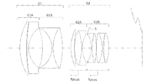
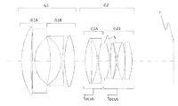
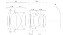
本発明の光学系は、第1の発明として、図1、図6、図11、図16、図21、図26及び図31に示す本発明の実施例の構成図からわかるように、物体側から像面側の順に、第1レンズ群G1と、正の屈折力を持つ第2レンズ群G2とからなり、
前記第1レンズ群G1は、物体側から像面側の順に、前記第1レンズ群G1の中で最も長い光軸上の空気間隔を隔てて、負の屈折力を持つ第1レンズ群前群G1Aと正の屈折力を持つ第1レンズ群後群G1Bとからなり、
前記第1レンズ群G1は、物体側から像面側の順に、前記第1レンズ群G1の中で最も長い光軸上の空気間隔を隔てて、負の屈折力を持つ第1レンズ群前群G1Aと正の屈折力を持つ第1レンズ群後群G1Bとからなり、
前記第1レンズ群前群G1Aの最も像面側の光学面は、像面側に凹面を向けており、
前記第1レンズ群後群G1Bの最も物体側の光学面は、物体側に凹面を向けており、
前記第1レンズ群後群G1Bの最も像面側の光学面は、像面側に凸面を向けており、
前記第2レンズ群G2は、物体側から像面側の順に、正の屈折力を持つ第2レンズ群前群G2Aと正の屈折力を持つ第2レンズ群後群G2Bとからなり、
無限遠物体から近距離物体へのフォーカシングに際して、前記第2レンズ群G2を光軸に沿って像面側から物体側へ移動し、以下に示す条件式(1)乃至(3)を満足することを特徴とする光学系。
(1) 1.50<|R1br/R1ar|<6.00
(2) 0.35<T/f<0.55
(3) 0.50<|f/R1bf|<1.50
f :無限遠物体合焦時における光学系全系の焦点距離
R1ar:前記第1レンズ群前群G1Aの最も像面側の光学面の曲率半径
R1bf:前記第1レンズ群後群G1Bの最も物体側の光学面の曲率半径
R1br:前記第1レンズ群後群G1Bの最も像面側の光学面の曲率半径
T :前記第1レンズ群後群G1Bの最も物体側の光学面から前記第1レンズ群後群G1Bの最も像側の光学面までの光軸上の距離
As can be seen from the configuration diagrams of the embodiments of the present invention shown in FIG. 1, FIG. 6, FIG. 11, FIG. 16, FIG. From the first lens group G1 and the second lens group G2 having a positive refractive power in order from the image surface side to
The first lens group G1 has a negative refractive power and a first lens group front group having a negative refractive power in order from the object side to the image plane side with the longest air interval on the optical axis in the first lens group G1. G1A and the first lens unit rear group G1B having a positive refractive power,
The first lens group G1 has a negative refractive power and a first lens group front group having a negative refractive power in order from the object side to the image plane side with the longest air interval on the optical axis in the first lens group G1. G1A and the first lens unit rear group G1B having a positive refractive power,
The optical surface closest to the image plane of the first lens group front group G1A has a concave surface facing the image plane side,
The most object side optical surface of the first lens group rear group G1B has a concave surface facing the object side,
The optical surface closest to the image plane of the first lens group rear group G1B has a convex surface facing the image plane side,
The second lens group G2 includes, in order from the object side to the image plane side, a second lens group front group G2A having a positive refractive power and a second lens group rear group G2B having a positive refractive power.
When focusing from an infinitely distant object to a close object, the second lens group G2 is moved from the image plane side to the object side along the optical axis, and the following conditional expressions (1) to (3) are satisfied. An optical system characterized by
(1) 1.50 <| R1br / R1ar | <6.00
(2) 0.35 <T / f <0.55
(3) 0.50 <| f / R1bf | <1.50
f: Focal length R1ar of the entire optical system at the time of focusing on an object at infinity: Radius of curvature R1bf of the optical surface closest to the image plane of the first lens group front group G1A: Most object of the first lens group rear group G1B Radius of curvature R1br of the optical surface on the side: curvature radius T of the optical surface closest to the image plane of the first lens group rear group G1B: the first lens from the optical surface closest to the object side of the rear group G1B of the first lens group The distance on the optical axis to the most image side optical surface of the rear group G1B
第1の発明である光学系の第1レンズ群G1は、その最も長い光軸上の空気間隔を隔てて、負の屈折力を持つ第1レンズ群前群G1Aと正の屈折力を持つ第1レンズ群後群G1Bとからなる。このような構成を取る事により、第1レンズ群G1がマージナル光線と光軸との距離を離すワイドコンバージョンレンズとして機能し、画角を広角化しつつバックフォーカスを確保する事が可能になった。 The first lens group G1 of the optical system according to the first aspect of the invention has a positive refractive power with respect to the first lens group front group G1A having a negative refractive power with an air space on the longest optical axis therebetween. 1 lens group rear group G1B. By adopting such a configuration, the first lens group G1 functions as a wide conversion lens that increases the distance between the marginal ray and the optical axis, and it is possible to ensure the back focus while widening the angle of view.
条件式(1)は前記第1レンズ群前群G1Aの最も像面側の光学面と前記第1レンズ群後群G1Bの最も像面側の光学面の曲率半径の比を規定するものである。この条件式を満たすことで、双方の面で発生したコマ収差や非点収差を適切に打ち消しあい良好な収差補正となる。 Conditional expression (1) defines the ratio of the radius of curvature of the optical surface closest to the image plane of the first lens group front group G1A and the optical surface closest to the image plane of the first lens group rear group G1B. . By satisfying this conditional expression, coma aberration and astigmatism generated on both surfaces are appropriately canceled out, and favorable aberration correction is achieved.
条件式(1)の上限値を超え、第1レンズ群前群G1Aの最も像面側の光学面の曲率が強くなると、この面で発生するコマ収差を補正することが困難になる。また、条件式(1)の下限値を超え、第1レンズ群後群G1Bの最も像面側の光学面の曲率が強くなると、この面で発生する非点収差や歪曲収差を補正することが困難になる。 If the upper limit of conditional expression (1) is exceeded and the curvature of the optical surface closest to the image surface of the first lens group front group G1A becomes strong, it becomes difficult to correct coma generated on this surface. If the lower limit of conditional expression (1) is exceeded and the curvature of the optical surface closest to the image plane of the first lens group rear group G1B becomes strong, astigmatism and distortion occurring on this surface can be corrected. It becomes difficult.
なお、上述した条件式(1)について、その下限値をさらに2.00に、また、上限値をさらに5.50とすることで、前述の効果をより確実にすることができる。 In the above-described conditional expression (1), the lower limit value is further set to 2.00 and the upper limit value is further set to 5.50, whereby the above-described effect can be further ensured.
条件式(2)は第1レンズ群後群G1Bの光軸上の全長を規定するものである。この条件式を満たすことで、第1レンズ群G1のワンドコンバージョンレンズとしての効果を確保しつつ、光学系の小型化に貢献し、製造誤差敏感度を抑制する事ができる。 Conditional expression (2) defines the total length on the optical axis of the first lens group rear group G1B. By satisfying this conditional expression, the effect of the first lens group G1 as a wand conversion lens can be secured, while contributing to the miniaturization of the optical system and suppressing the manufacturing error sensitivity.
条件式(2)の上限値を超え、第1レンズ群後群G1Bの全長が長くなると、光学全長が増大する他、像側のレンズの径が拡大し、偏芯等の製造公差による性能低下が発生し易くなる。また、条件式(2)の下限値を超え、第1レンズ群後群G1Bの全長が短くなると、第2レンズ群G2に入射するマージナル光線と光軸との距離が十分離す事ができず、バックフォーカスの確保が困難になる。 When the upper limit of conditional expression (2) is exceeded and the total length of the first lens group rear group G1B is increased, the optical total length is increased, the diameter of the lens on the image side is increased, and performance is deteriorated due to manufacturing tolerances such as decentration. Is likely to occur. If the lower limit of conditional expression (2) is exceeded and the total length of the first lens group rear group G1B is shortened, the distance between the marginal ray incident on the second lens group G2 and the optical axis cannot be sufficiently separated. It becomes difficult to secure the back focus.
なお、上述の条件式(2)について、その下限値をさらに0.40に、また、上限値をさらに0.50とすることで、前述の効果をより確実にすることができる。 In addition, regarding the above-described conditional expression (2), the lower limit value is further set to 0.40, and the upper limit value is further set to 0.50, whereby the above-described effect can be further ensured.
条件式(3)は前記第1レンズ群後群G1Bの最も物体側の光学面の曲率半径を規定するものである。この条件式を満たすことで、第1レンズ群G1内で歪曲収差等の諸収差を適切に補正する効果が得られる。 Conditional expression (3) defines the radius of curvature of the optical surface closest to the object side in the first lens group rear group G1B. By satisfying this conditional expression, an effect of appropriately correcting various aberrations such as distortion in the first lens group G1 can be obtained.
条件式(3)の上限値を超え、第1レンズ群後群G1Bの最も物体側の光学面の曲率が強くなると、負の歪曲収差を補正する事が困難になる他、偏芯等の製造公差による性能低下が発生し易くなる。また、条件式(3)の下限値を超え、第1レンズ群後群G1Bの最も物体側の光学面の曲率が弱くなると、正の歪曲収差や非点収差を補正する事が困難になる。 If the upper limit of conditional expression (3) is exceeded and the curvature of the optical surface closest to the object side in the first lens group rear group G1B becomes strong, it becomes difficult to correct negative distortion, and manufacture of decentration, etc. Performance degradation due to tolerances is likely to occur. If the lower limit of conditional expression (3) is exceeded and the curvature of the optical surface closest to the object side in the first lens group rear group G1B becomes weak, it becomes difficult to correct positive distortion and astigmatism.
なお、上述の条件式(3)について、その下限値をさらに0.55に、また、上限値をさらに1.20とすることで、前述の効果をより確実にすることができる。 In addition, regarding the conditional expression (3), the lower limit value is further set to 0.55, and the upper limit value is further set to 1.20, whereby the above-described effect can be further ensured.
また第2の発明である光学系は、第1の発明であって、さらに前記第1レンズ群前群G1Aは、その最も物体側に、物体側に凸面を向けた正の屈折力を持つレンズを有し、前記第1レンズ群後群G1Bは、その最も像面側に、正の屈折力を持つレンズを有することを特徴とする。 An optical system according to a second aspect of the invention is the first aspect of the invention, and the first lens group front group G1A has a positive refractive power with a convex surface facing the object side closest to the object side. The first lens group rear group G1B has a lens having a positive refractive power on the most image side.
第2の発明である光学系の第1レンズ群前群G1Aは、その最も物体側に、物体側に凸面を向けた正の屈折力を持つレンズを有し、前記第1レンズ群後群G1Bは、その最も像面側に、正の屈折力を持つレンズを有する。このような構成を取る事により、第1レンズ群G1がレンズの径方向のサイズを抑制しながらワンドコンバージョンレンズとしての効果を確保しつつ、群内で歪曲収差を補正でき、全合焦域で歪曲収差を抑える事が可能となる。 The first lens group front group G1A of the optical system according to the second aspect of the invention has a lens having a positive refractive power with a convex surface facing the object side closest to the object side, and the first lens group rear group G1B Has a lens having a positive refractive power on the most image side. By adopting such a configuration, the first lens group G1 can correct distortion aberration within the group while ensuring the effect as a wand conversion lens while suppressing the size of the lens in the radial direction. It becomes possible to suppress distortion.
また第3の発明である光学系は、第1の発明または第2の発明であって、さらに前記第2レンズ群前群G2Aと前記第2レンズ群後群G2Bは、前記第2レンズ群G2の中で最も長い光軸上の空気間隔で隔てられ、以下に示す条件式(4)乃至(5)を満足することを特徴とする。
(4) 1.80<nd2p
(5) 0.50<|R2bf/R2ar|<1.50
nd2p:前記第2レンズ群前群G2Aの最も屈折率の高い正の屈折力を持つレンズの屈折率
R2ar:前記第2レンズ群前群G2Aの最も像側の光学面の曲率半径
R2bf:前記第2レンズ群後群G2Bの最も物体側の光学面の曲率半径
An optical system according to a third invention is the first invention or the second invention, and the second lens group front group G2A and the second lens group rear group G2B further include the second lens group G2. Are separated by an air interval on the longest optical axis, and satisfy the following conditional expressions (4) to (5).
(4) 1.80 <nd2p
(5) 0.50 <| R2bf / R2ar | <1.50
nd2p: refractive index R2ar of the lens having positive refractive power with the highest refractive index of the second lens group front group G2A: radius of curvature R2bf of the optical surface closest to the image side of the second lens group front group G2A: The radius of curvature of the optical surface closest to the object side in the two-lens group rear group G2B
第3の発明である光学系の第2レンズ群前群G2aと第2レンズ群後群G2bは、第2レンズ群G2の中で最も長い光軸上の空気間隔で隔てられる。このような構成を取る事で、第2レンズ群前群G2aと第2レンズ群後群G2bの間に光学絞りやフィルタ等を挿入するスペースを確保する事が可能となる。 The second lens group front group G2a and the second lens group rear group G2b of the optical system according to the third aspect of the invention are separated by the longest air space on the optical axis in the second lens group G2. By adopting such a configuration, it is possible to secure a space for inserting an optical aperture, a filter, or the like between the second lens group front group G2a and the second lens group rear group G2b.
条件式(4)は第2レンズ群前群G2Aを構成する正の屈折力を持つレンズの内で、最も屈折率が高いレンズの屈折率を規定するものである。この条件式を満たすことで、第2レンズ群G2の中の、他の正の屈折力を持つレンズに、軸上色収差の補正上有利な特殊低分散ガラス等の屈折率の低い材料を採用しても、非点収差や像面湾曲を抑制する事が可能となる。 Conditional expression (4) defines the refractive index of the lens having the highest refractive index among the lenses having the positive refractive power constituting the second lens group front group G2A. By satisfying this conditional expression, a low refractive index material such as special low dispersion glass, which is advantageous in correcting axial chromatic aberration, is adopted for the other lenses having the positive refractive power in the second lens group G2. However, astigmatism and curvature of field can be suppressed.
条件式(4)の下限値を超え、第2レンズ群前群G2Aを構成する正の屈折力を持つレンズの最大の屈折率が低くなると、非点収差や像面湾曲の補正と軸上色収差の補正を両立させることが困難になる。 If the maximum refractive index of the lens having the positive refractive power that constitutes the second lens unit front group G2A is lower than the lower limit value of the conditional expression (4), correction of astigmatism and field curvature and axial chromatic aberration are performed. It is difficult to achieve both corrections.
なお、条件式(4)について、その下限値をさらに1.85とすることで、前述の効果をより確実にすることができる。 In addition, regarding the conditional expression (4), when the lower limit value is further set to 1.85, the above-described effect can be further ensured.
条件式(5)は第2レンズ群前群G2Aの最も像面側の光学面と第2レンズ群後群G2Bの最も物体側の光学面の曲率半径の比を規定するものである。この条件式を満たすことで、双方の面で発生したコマ収差や歪曲収差を適切に打ち消しあい良好な収差補正となる。 Conditional expression (5) defines the ratio of the radius of curvature of the optical surface closest to the image plane of the second lens group front group G2A and the optical surface closest to the object side of the second lens group rear group G2B. By satisfying this conditional expression, coma aberration and distortion occurring on both surfaces are appropriately canceled out, and good aberration correction is achieved.
条件式(5)の上限値を超え、第2レンズ群後群G2Bの最も物体側の光学面の曲率に対する第2レンズ群前群G2Aの最も像面側の光学面の曲率が強くなると、この面で発生する高次のコマ収差や歪曲収差を補正することが困難になる。また、条件式(5)の下限値を超え、第2レンズ群前群G2Aの最も像面側の光学面の曲率に対する第2レンズ群後群G2Bの最も物体側の光学面の曲率が強くなると、この面で発生するコマ収差を補正することが困難になる。 When the upper limit of conditional expression (5) is exceeded and the curvature of the optical surface closest to the image plane of the second lens group front group G2A is stronger than the curvature of the optical surface closest to the object side of the second lens group rear group G2B, It becomes difficult to correct higher-order coma and distortion occurring on the surface. When the lower limit of conditional expression (5) is exceeded, the curvature of the optical surface closest to the object side in the second lens group rear group G2B with respect to the curvature of the optical surface closest to the image surface in the second lens group front group G2A becomes stronger. Therefore, it becomes difficult to correct coma generated on this surface.
なお、条件式(5)について、その下限値をさらに0.70に、また、上限値をさらに1.20とすることで、前述の効果をより確実にすることができる。 For conditional expression (5), the lower limit value is further set to 0.70, and the upper limit value is further set to 1.20, whereby the above-described effect can be further ensured.
また第4の発明である光学系は、第1の発明乃至第3の発明のいずれかであって、さらに以下に示す条件式(6)乃至(8)を満足することを特徴とする。
(6) 0.20<|f/f1a|<0.50
(7) 0.20<f/f1b<0.60
(8) 0.20<f/f2a<0.60
(9) 0.50<f/f2b<1.00
f :無限遠物体合焦時における光学系全系の焦点距離
f1a:前記第1レンズ群前群G1Aの焦点距離
f1b:前記第1レンズ群後群G1Bの焦点距離
f2a:前記第2レンズ群前群G2Aの焦点距離
f2b:前記第2レンズ群後群G2Bの焦点距離
An optical system according to a fourth invention is any one of the first invention to the third invention, and further satisfies the following conditional expressions (6) to (8).
(6) 0.20 <| f / f1a | <0.50
(7) 0.20 <f / f1b <0.60
(8) 0.20 <f / f2a <0.60
(9) 0.50 <f / f2b <1.00
f: focal length of the entire optical system when focusing on an object at infinity f1a: focal length of the first lens group front group G1A f1b: focal length of the first lens group rear group G1B f2a: front of the second lens group Focal length f2b of group G2A: Focal length of rear group G2B of the second lens group
条件式(6)は第1レンズ群前群G1Aの焦点距離を規定するものである。この条件式を満たすことで、第1レンズ群G1のワンドコンバージョンレンズとしての効果を確保しつつ、光学系のサイズを抑え、歪曲収差等の諸収差を補正する事ができる。 Conditional expression (6) defines the focal length of the first lens group front group G1A. By satisfying this conditional expression, the size of the optical system can be suppressed and various aberrations such as distortion can be corrected while securing the effect of the first lens group G1 as a wand conversion lens.
条件式(6)の上限値を超え、第1レンズ群前群G1Aの負の屈折力が強くなると、第1レンズ群後群G1Bの径が拡大し製品の径が拡大する他、コマ収差や歪曲収差を補正することが困難になる。また、条件式(6)の下限値を超え、第1レンズ群前群G1Aの負の屈折力が弱くなると、バックフォーカスを確保する事が困難になる他、物体側のレンズの径が拡大し易くなる。 When the upper limit of conditional expression (6) is exceeded and the negative refractive power of the first lens group front group G1A becomes strong, the diameter of the first lens group rear group G1B increases, the product diameter increases, coma aberration, It becomes difficult to correct distortion. If the lower limit of conditional expression (6) is exceeded and the negative refractive power of the first lens unit front group G1A becomes weaker, it becomes difficult to secure the back focus and the diameter of the lens on the object side increases. It becomes easy.
なお、条件式(6)について、その下限値をさらに0.25に、また、上限値をさらに0.45とすることで、前述の効果をより確実にすることができる。 For conditional expression (6), the lower limit value is further set to 0.25, and the upper limit value is further set to 0.45, whereby the above-described effect can be further ensured.
条件式(7)は第1レンズ群後群G1Bの焦点距離を規定するものである。この条件式を満たすことで、光学系のサイズを抑えつつ、コマ収差等の諸収差、製造誤差敏感度を改善する事ができる。 Conditional expression (7) defines the focal length of the first lens group rear group G1B. By satisfying this conditional expression, it is possible to improve various aberrations such as coma aberration and manufacturing error sensitivity while suppressing the size of the optical system.
条件式(7)の上限値を超え、第1レンズ群後群G1Bの正の屈折力が強くなると、偏芯等の製造公差による性能低下が発生し易くなる他、コマ収差や非点収差を補正することが困難になる。また、条件式(7)の下限値を超え、第1レンズ群後群G1Bの正の屈折力が弱くなると、第2レンズ群G2の径が拡大し製品の径も拡大する他、第2レンズ群前群G2Aの正のパワーの負担が増え、収差を補正する上で好ましくない。 If the upper limit of conditional expression (7) is exceeded and the positive refractive power of the first lens group rear group G1B is increased, performance deterioration due to manufacturing tolerances such as decentration is likely to occur, and coma and astigmatism are reduced. It becomes difficult to correct. If the lower limit of conditional expression (7) is exceeded and the positive refractive power of the first lens group rear group G1B becomes weaker, the diameter of the second lens group G2 increases and the product diameter also increases. The burden on the positive power of the front group G2A increases, which is not preferable for correcting aberrations.
なお、条件式(7)について、その下限値をさらに0.22に、また、上限値をさらに0.55とすることで、前述の効果をより確実にすることができる。 For conditional expression (7), the lower limit value is further set to 0.22 and the upper limit value is further set to 0.55, whereby the above-described effect can be further ensured.
条件式(8)は第2レンズ群前群G2Aの焦点距離を規定するものである。この条件式を満たすことで、光学系のサイズを抑えつつ、軸上色収差と非点収差をバランスよく改善する事ができる。 Conditional expression (8) defines the focal length of the second lens group front group G2A. By satisfying this conditional expression, axial chromatic aberration and astigmatism can be improved in a balanced manner while suppressing the size of the optical system.
条件式(8)の上限値を超え、第1レンズ群前群G2Aの正の屈折力が強くなると、軸上色収差を抑制しつつ球面収差や非点収差を補正することが困難になる。また、条件式(8)の下限値を超え、第2レンズ群前群G2Aの正の屈折力が弱くなると、第2レンズ群後群G2Bと歪曲収差補正等のバランスを取る事が困難になる他、第2レンズ群前群G2Aと第2レンズ群後群G2Bの間に光学絞りを配置する場合、光学絞りの径が拡大する。 When the upper limit of conditional expression (8) is exceeded and the positive refractive power of the first lens group front group G2A becomes strong, it becomes difficult to correct spherical aberration and astigmatism while suppressing axial chromatic aberration. When the lower limit of conditional expression (8) is exceeded and the positive refractive power of the second lens group front group G2A becomes weak, it becomes difficult to balance the second lens group rear group G2B with distortion correction and the like. In addition, when the optical aperture is disposed between the second lens group front group G2A and the second lens group rear group G2B, the diameter of the optical aperture is increased.
なお、条件式(8)について、その下限値をさらに0.25に、また、上限値をさらに0.55とすることで、前述の効果をより確実にすることができる。 For conditional expression (8), the lower limit value is further set to 0.25, and the upper limit value is further set to 0.55, whereby the above-described effect can be further ensured.
条件式(9)は第2レンズ群後群G2Bの焦点距離を規定するものである。この条件式を満たすことで、光学系のサイズを抑えつつ、軸上色収差と非点収差をバランスよく改善する事ができる。 Conditional expression (9) defines the focal length of the second lens group rear group G2B. By satisfying this conditional expression, axial chromatic aberration and astigmatism can be improved in a balanced manner while suppressing the size of the optical system.
条件式(9)の上限値を超え、第2レンズ群後群G2Bの正の屈折力が強くなると、軸上色収差を抑制しつつコマ収差や非点収差を補正することが困難になる。また、条件式(9)の下限値を超え、第2レンズ群後群G2Bの正の屈折力が弱くなると、第2レンズ群G2の径が拡大し製品の径が拡大する他、第2レンズ群前群G2Aの正の屈折力の負担が増え、収差補正上好ましくない。 If the upper limit of conditional expression (9) is exceeded and the positive refractive power of the second lens group rear group G2B becomes strong, it becomes difficult to correct coma and astigmatism while suppressing axial chromatic aberration. When the lower limit of conditional expression (9) is exceeded and the positive refractive power of the second lens group rear group G2B becomes weak, the diameter of the second lens group G2 increases and the diameter of the product increases. The burden on the positive refractive power of the front group G2A increases, which is not preferable for aberration correction.
なお、条件式(9)について、その下限値をさらに0.60に、また、上限値をさらに0.80とすることで、前述の効果をより確実にすることができる。 For conditional expression (9), the lower limit value is further set to 0.60, and the upper limit value is further set to 0.80, whereby the above-described effect can be further ensured.
以下に前述した本発明の光学系に係る実施例1乃至8の数値データを示す。 Numerical data of Examples 1 to 8 relating to the optical system of the present invention described above are shown below.
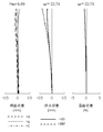
[面データ]において、面番号は物体側から数えたレンズ面又は開口絞りの番号、rは各面の曲率半径、dは各面の間隔、ndはd線(波長λ=587.6nm)に対する屈折率、νdはd線(波長λ=587.6nm)に対するアッベ数を示している。 In [Surface Data], the surface number is the number of the lens surface or aperture stop counted from the object side, r is the radius of curvature of each surface, d is the distance between the surfaces, and nd is for the d-line (wavelength λ = 587.6 nm). The refractive index, νd, indicates the Abbe number with respect to the d-line (wavelength λ = 587.6 nm).
面番号に付した*(アスタリスク)は、そのレンズ面形状が非球面であることを示している。また、BFはバックフォーカスを表している。 The * (asterisk) attached to the surface number indicates that the lens surface shape is an aspherical surface. BF represents back focus.
面番号に付した(絞り)は、その位置に開口絞りSが位置していることを示している。平面又は開口絞りSに対する曲率半径には∞(無限大)を記入している。(フレアカット絞り)はフレアカット絞り面を示している。 The (diaphragm) attached to the surface number indicates that the aperture stop S is located at that position. ∞ (infinity) is entered in the radius of curvature for the plane or aperture stop S. (Flare cut stop) indicates a flare cut stop surface.
[非球面データ]には、[面データ]において*を付したレンズ面の非球面形状を与える各係数値を示している。非球面の形状は、非球面の形状は、光軸に直行する方向への光軸からの変位をy、非球面と光軸の交点から光軸方向への変位(サグ量)をz、基準球面の曲率半径をr、コーニック係数をK、4、6、8、10次の非球面係数をそれぞれA4、A6、A8、A10と置くとき、非球面の座標が以下の式で表されるものとする。

[各種データ]には、各焦点距離状態における焦点距離等の値を示している。 [Various data] shows values such as the focal length in each focal length state.
[可変間隔データ]には、各レンズ群を構成する最も物体側の面番号及び群全体の合成焦点距離を示している。 [Variable interval data] indicates the surface number of the most object side constituting each lens group and the combined focal length of the entire group.
なお、以下の全ての諸元の値において、記載している焦点距離f、曲率半径r、レンズ面間隔d、その他の長さの他には特記のない限りミリメートル(mm)を使用するが、光学系では比例拡大と比例縮小とにおいても同等の光学性能が得られるので、これに限られるものではない。 In addition, in the values of all the following specifications, millimeters (mm) are used unless otherwise specified, except for the described focal length f, radius of curvature r, lens surface interval d, and other lengths. In the optical system, the same optical performance can be obtained in proportional enlargement and proportional reduction, and the present invention is not limited to this.
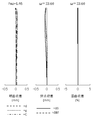
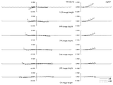
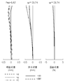
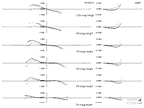
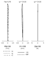
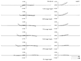
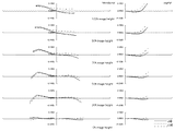
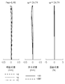
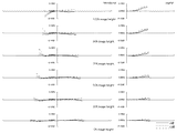
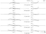
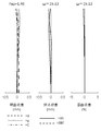
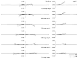
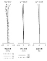
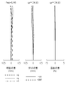
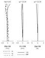
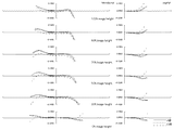
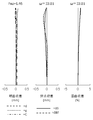
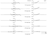
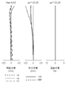
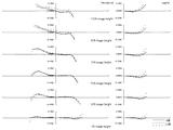
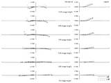
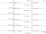
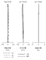
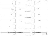
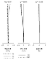
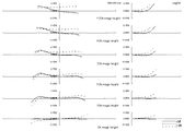
また、各実施例に対応する収差図において、d、g、Cはそれぞれd線、g線、C線を表しており、ΔS、ΔMはそれぞれサジタル像面、メリジオナル像面を表している。 In the aberration diagrams corresponding to each example, d, g, and C represent d-line, g-line, and C-line, respectively, and ΔS and ΔM represent sagittal image plane and meridional image plane, respectively.
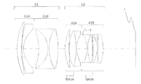
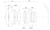
さらに、図1、図6、図11、図16、図21、図26、図31及び図36に示すレンズ構成図において、Iは像面、中心を通る一点鎖線は光軸である。 Furthermore, in the lens configuration diagrams shown in FIGS. 1, 6, 11, 16, 21, 26, 31, and 36, I is the image plane, and the alternate long and short dash line through the center is the optical axis.
次に、本発明の光学系に係る実施例のレンズ構成について説明する。なお、以下の説明ではレンズ構成を物体側から像面側の順番で記載する。 Next, a lens configuration of an example according to the optical system of the present invention will be described. In the following description, lens configurations are described in order from the object side to the image plane side.
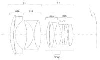
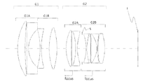
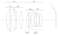
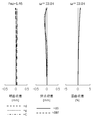
図1は、本発明の実施例1の光学系の無限遠合焦時におけるレンズ構成図である。 FIG. 1 is a lens configuration diagram of the optical system according to Example 1 of the present invention when focusing on infinity.
図1の光学系は、物体側から像面側の順に、全体として正の屈折力を持つ第1レンズ群G1と、全体として正の屈折力を持つ第2レンズ群G2とから構成される。 The optical system in FIG. 1 includes a first lens group G1 having a positive refractive power as a whole and a second lens group G2 having a positive refractive power as a whole in order from the object side to the image plane side.
第1レンズ群G1は、第1レンズ群前群G1Aと第1レンズ群後群G1Bとから成る。また、第1レンズ群G1は、無限遠物体から近距離物体へのフォーカシングに際して像面に対する位置が固定である。 The first lens group G1 includes a first lens group front group G1A and a first lens group rear group G1B. The first lens group G1 is fixed in position with respect to the image plane during focusing from an infinitely distant object to a close object.
第1レンズ群前群G1Aは、物体側に凸面を向けた正メニスカスレンズ及び物体側に凸面を向けた負メニスカスレンズから構成され、全体として負の屈折力を持つ。 The first lens group front group G1A includes a positive meniscus lens having a convex surface directed toward the object side and a negative meniscus lens having a convex surface directed toward the object side, and has a negative refracting power as a whole.
第1レンズ群後群G1Bは、物体側に凹面を向けた正メニスカスレンズと両凹レンズと両凸レンズとから成る正の屈折力を持つ3枚接合レンズで構成される。また、第1レンズ群後群G1Bの像面側にフレアカット絞りを設ける。 The first lens group rear group G1B is constituted by a three-piece cemented lens having a positive refractive power, which includes a positive meniscus lens having a concave surface directed toward the object side, a biconcave lens, and a biconvex lens. In addition, a flare cut stop is provided on the image plane side of the first lens group rear group G1B.
第2レンズ群G2は、第2レンズ群前群G2Aと第2レンズ群後群G2Bとから成り、全体として正の屈折力を持つ。また、第2レンズ群前群G2Aと第2レンズ群後群G2Bは、無限遠物体から近距離物体へのフォーカシングに際して、互いに独立して物体側へ移動する。 The second lens group G2 includes a second lens group front group G2A and a second lens group rear group G2B, and has a positive refractive power as a whole. Further, the second lens group front group G2A and the second lens group rear group G2B move to the object side independently of each other during focusing from an object at infinity to a short distance object.
第2レンズ群前群G2Aは、物体側に凸面を向けた正メニスカスレンズ、及び両凸レンズと両凹レンズとから成る負の屈折力を持つ接合レンズで構成され、全体として正の屈折力を持つ。 The second lens group front group G2A includes a positive meniscus lens having a convex surface directed toward the object side, and a cemented lens having a negative refractive power including a biconvex lens and a biconcave lens, and has a positive refractive power as a whole.
開口絞りSは、第2レンズ群前群G2Aと第2レンズ群後群G2Bとの間に配置され、無限遠物体から近距離物体へのフォーカシングに際して、第2レンズ群後群G2Bと同じ軌跡で物体側へ移動する。 The aperture stop S is disposed between the second lens group front group G2A and the second lens group rear group G2B, and has the same locus as the second lens group rear group G2B when focusing from an infinite object to a short distance object. Move to the object side.
第2レンズ群後群G2Bは、両凹レンズと両凸レンズから成る負の屈折力を持つ接合レンズ、両凸レンズと両凹レンズから成る正の屈折力を持つ接合レンズ、及び物体側像面側両面に非球面を形成した両凸レンズから構成され、全体として正の屈折力を持つ。 The second lens group rear group G2B includes a cemented lens having a negative refractive power composed of a biconcave lens and a biconvex lens, a cemented lens having a positive refractive power composed of a biconvex lens and a biconcave lens, and a non-convex lens on both sides of the object side image surface. It consists of a biconvex lens with a spherical surface, and has positive refractive power as a whole.
続いて、以下に実施例1に係る光学系の諸元値を示す。
数値実施例1
単位:mm
[面データ]
面番号 r d nd vd
物面 ∞ (d0)
1 59.9687 7.5464 1.91082 35.25
2 178.4018 0.6242
3 192.0154 2.0000 1.62588 35.74
4 28.7552 16.1562
5 -67.9622 10.7338 1.49700 81.61
6 -26.2761 1.5000 1.54814 45.82
7 43.9346 10.7524 1.88300 40.81
8 -94.4447 0.0000
9(フレアカット絞り) ∞ (d9)
10 49.8944 3.9121 1.92286 20.88
11 108.4891 0.1500
12 47.6761 8.0538 1.72916 54.67
13 -69.2432 0.9500 1.72825 28.32
14 31.4317 (d14)
15(絞り) ∞ 4.6436
16 -31.6556 0.9500 1.62588 35.74
17 71.6171 4.6610 1.59282 68.62
18 -96.5972 0.1500
19 85.5221 6.6571 1.59282 68.62
20 -40.3262 0.9500 1.51742 52.15
21 57.5543 0.9291
22* 77.4702 5.8822 1.77250 49.47
23* -47.5092 (BF)
像面 ∞
[非球面データ]
22面 23面
K 0.00000 0.00000
A4 -9.93095E-07 3.17495E-06
A6 1.24366E-09 -1.01711E-10
A8 -7.51084E-13 2.00250E-12
A10 0.00000E+00 -1.26705E-15
[各種データ]
INF 400mm
焦点距離 49.58 48.35
Fナンバー 1.46 1.67
全画角2ω 47.19 43.47
像高Y 21.63 21.63
レンズ全長 142.00 142.00
[可変間隔データ]
INF 400mm
d0 ∞ 258.0000
d9 9.9796 1.2000
d14 6.0186 5.8989
BF 38.7999 47.6991
[レンズ群データ]
群 始面 焦点距離
G1 1 282.98
G1A 1 -153.20
G1B 5 114.66
G2A 10 173.27
G2B 15 65.28
Subsequently, specification values of the optical system according to Example 1 are shown below.
Numerical example 1
Unit: mm
[Surface data]
Surface number rd nd vd
Object ∞ (d0)
1 59.9687 7.5464 1.91082 35.25
2 178.4018 0.6242
3 192.0154 2.0000 1.62588 35.74
4 28.7552 16.1562
5 -67.9622 10.7338 1.49700 81.61
6 -26.2761 1.5000 1.54814 45.82
7 43.9346 10.7524 1.88300 40.81
8 -94.4447 0.0000
9 (Flare cut aperture) ∞ (d9)
10 49.8944 3.9121 1.92286 20.88
11 108.4891 0.1500
12 47.6761 8.0538 1.72916 54.67
13 -69.2432 0.9500 1.72825 28.32
14 31.4317 (d14)
15 (Aperture) ∞ 4.6436
16 -31.6556 0.9500 1.62588 35.74
17 71.6171 4.6610 1.59282 68.62
18 -96.5972 0.1500
19 85.5221 6.6571 1.59282 68.62
20 -40.3262 0.9500 1.51742 52.15
21 57.5543 0.9291
22 * 77.4702 5.8822 1.77250 49.47
23 * -47.5092 (BF)
Image plane ∞
[Aspherical data]
22 faces 23 faces
K 0.00000 0.00000
A4 -9.93095E-07 3.17495E-06
A6 1.24366E-09 -1.01711E-10
A8 -7.51084E-13 2.00250E-12
A10 0.00000E + 00 -1.26705E-15
[Various data]
INF 400mm
Focal length 49.58 48.35
F number 1.46 1.67
Full angle of view 2ω 47.19 43.47
Statue height Y 21.63 21.63
Total lens length 142.00 142.00
[Variable interval data]
INF 400mm
d0 ∞ 258.0000
d9 9.9796 1.2000
d14 6.0186 5.8989
BF 38.7999 47.6991
[Lens group data]
Group Start surface Focal length
G1 1 282.98
G1A 1 -153.20
G2A 10 173.27
G2B 15 65.28
図6は、本発明の実施例2の光学系の無限遠合焦時におけるレンズ構成図である。 FIG. 6 is a lens configuration diagram of the optical system according to Example 2 of the present invention when focusing on infinity.
図6の光学系は、物体側から像面側の順に、全体として正の屈折力を持つ第1レンズ群G1と、全体として正の屈折力を持つ第2レンズ群G2とから構成される。 The optical system shown in FIG. 6 includes a first lens group G1 having a positive refractive power as a whole and a second lens group G2 having a positive refractive power as a whole in order from the object side to the image plane side.
第1レンズ群G1は、第1レンズ群前群G1Aと第1レンズ群後群G1Bとから成る。また、第1レンズ群G1は、無限遠物体から近距離物体へのフォーカシングに際して像面に対する位置が固定である。 The first lens group G1 includes a first lens group front group G1A and a first lens group rear group G1B. The first lens group G1 is fixed in position with respect to the image plane during focusing from an infinitely distant object to a close object.
第1レンズ群前群G1Aは、物体側に凸面を向けた正メニスカスレンズ及び物体側に凸面を向けた負メニスカスレンズから構成され、全体として負の屈折力を持つ。 The first lens group front group G1A includes a positive meniscus lens having a convex surface directed toward the object side and a negative meniscus lens having a convex surface directed toward the object side, and has a negative refracting power as a whole.
第1レンズ群後群G1Bは、物体側に凹面を向けた正メニスカスレンズと両凹レンズと両凸レンズとから成る正の屈折力を持つ3枚接合レンズで構成される。また、第1レンズ群後群G1Bの像面側にフレアカット絞りを設ける。 The first lens group rear group G1B is constituted by a three-piece cemented lens having a positive refractive power, which includes a positive meniscus lens having a concave surface directed toward the object side, a biconcave lens, and a biconvex lens. In addition, a flare cut stop is provided on the image plane side of the first lens group rear group G1B.
第2レンズ群G2は、第2レンズ群前群G2Aと第2レンズ群後群G2Bとから成り、全体として正の屈折力を持つ。また、第2レンズ群前群G2Aと第2レンズ群後群G2Bは、無限遠物体から近距離物体へのフォーカシングに際して、互いに独立して物体側へ移動する。 The second lens group G2 includes a second lens group front group G2A and a second lens group rear group G2B, and has a positive refractive power as a whole. Further, the second lens group front group G2A and the second lens group rear group G2B move to the object side independently of each other during focusing from an object at infinity to a short distance object.
第2レンズ群前群G2Aは、物体側に凸面を向けた正メニスカスレンズ、及び両凸レンズと両凹レンズとから成る負の屈折力を持つ接合レンズで構成され、全体として正の屈折力を持つ。 The second lens group front group G2A includes a positive meniscus lens having a convex surface directed toward the object side, and a cemented lens having a negative refractive power including a biconvex lens and a biconcave lens, and has a positive refractive power as a whole.
開口絞りSは、第2レンズ群前群G2Aと第2レンズ群後群G2Bとの間に配置され、無限遠物体から近距離物体へのフォーカシングに際して、第2レンズ群後群G2Bと同じ軌跡で物体側へ移動する。 The aperture stop S is disposed between the second lens group front group G2A and the second lens group rear group G2B, and has the same locus as the second lens group rear group G2B when focusing from an infinite object to a short distance object. Move to the object side.
第2レンズ群後群G2Bは、両凹レンズと両凸レンズから成る負の屈折力を持つ接合レンズ、物体側に凹面を向けた正メニスカスレンズと像面側に凸面を向けた負メニスカスレンズから成る正の屈折力を持つ接合レンズ、及び物体側像面側両面に非球面を形成した両凸レンズから構成され、全体として正の屈折力を持つ。 The second lens group rear group G2B includes a cemented lens having a negative refractive power including a biconcave lens and a biconvex lens, a positive meniscus lens having a concave surface on the object side, and a negative meniscus lens having a convex surface on the image side. And a biconvex lens in which aspheric surfaces are formed on both surfaces on the object side image surface side, and has a positive refractive power as a whole.
続いて、以下に実施例2に係る光学系の諸元値を示す。
数値実施例2
単位:mm
[面データ]
面番号 r d nd vd
物面 ∞ (d0)
1 67.5814 5.3292 1.95375 32.32
2 130.0875 0.4000
3 94.5475 2.0000 1.58144 40.89
4 27.9000 18.2013
5 -59.3951 10.9270 1.55332 71.68
6 -25.1731 1.4000 1.60342 38.01
7 44.6540 10.8848 1.88300 40.81
8 -85.7707 0.0000
9(フレアカット絞り) ∞ (d9)
10 52.6706 4.6589 1.92286 20.88
11 216.9523 0.1500
12 47.4352 8.1142 1.72916 54.67
13 -94.6784 0.9500 1.72825 28.32
14 31.2801 (d14)
15(絞り) ∞ 5.5017
16 -31.0428 0.9000 1.64769 33.84
17 49.6877 5.6695 1.59282 68.62
18 -84.4975 0.1500
19 -549.5685 4.9878 1.59282 68.62
20 -36.1297 0.9000 1.51742 52.15
21 -386.2514 0.3595
22* 180.2764 6.2315 1.77250 49.47
23* -44.1428 (BF)
像面 ∞
[非球面データ]
22面 23面
K 0.00000 0.00000
A4 -1.99497E-06 2.23091E-06
A6 8.32607E-10 -6.25203E-10
A8 -5.11430E-12 -1.61803E-12
A10 3.33468E-15 0.00000E+00
[各種データ]
INF 400mm
焦点距離 47.24 46.37
Fナンバー 1.46 1.69
全画角2ω 49.17 45.50
像高Y 21.63 21.63
レンズ全長 142.00 142.00
[可変間隔データ]
INF 400mm
d0 ∞ 258.0000
d9 8.4672 1.2000
d14 7.0173 5.8935
BF 38.8001 47.1911
[レンズ群データ]
群 始面 焦点距離
G1 1 640.64
G1A 1 -149.73
G1B 5 150.39
G2A 10 107.16
G2B 15 71.85
Subsequently, specification values of the optical system according to Example 2 are shown below.
Numerical example 2
Unit: mm
[Surface data]
Surface number rd nd vd
Object ∞ (d0)
1 67.5814 5.3292 1.95375 32.32
2 130.0875 0.4000
3 94.5475 2.0000 1.58144 40.89
4 27.9000 18.2013
5 -59.3951 10.9270 1.55332 71.68
6 -25.1731 1.4000 1.60342 38.01
7 44.6540 10.8848 1.88300 40.81
8 -85.7707 0.0000
9 (Flare cut aperture) ∞ (d9)
10 52.6706 4.6589 1.92286 20.88
11 216.9523 0.1500
12 47.4352 8.1142 1.72916 54.67
13 -94.6784 0.9500 1.72825 28.32
14 31.2801 (d14)
15 (Aperture) ∞ 5.5017
16 -31.0428 0.9000 1.64769 33.84
17 49.6877 5.6695 1.59282 68.62
18 -84.4975 0.1500
19 -549.5685 4.9878 1.59282 68.62
20 -36.1297 0.9000 1.51742 52.15
21 -386.2514 0.3595
22 * 180.2764 6.2315 1.77250 49.47
23 * -44.1428 (BF)
Image plane ∞
[Aspherical data]
22 faces 23 faces
K 0.00000 0.00000
A4 -1.99497E-06 2.23091E-06
A6 8.32607E-10 -6.25203E-10
A8 -5.11430E-12 -1.61803E-12
A10 3.33468E-15 0.00000E + 00
[Various data]
INF 400mm
Focal length 47.24 46.37
F number 1.46 1.69
Full angle of view 2ω 49.17 45.50
Statue height Y 21.63 21.63
Total lens length 142.00 142.00
[Variable interval data]
INF 400mm
d0 ∞ 258.0000
d9 8.4672 1.2000
d14 7.0173 5.8935
BF 38.8001 47.1911
[Lens group data]
Group Start surface Focal length
G1 1 640.64
G1A 1 -149.73
G2A 10 107.16
G2B 15 71.85
図11は、本発明の実施例3の光学系の無限遠合焦時におけるレンズ構成図である。 FIG. 11 is a lens configuration diagram of the optical system according to Example 3 of the present invention when focused on infinity.
図11の光学系は、物体側から像面側の順に、全体として正の屈折力を持つ第1レンズ群G1と、全体として正の屈折力を持つ第2レンズ群G2とから構成される。 The optical system shown in FIG. 11 includes a first lens group G1 having a positive refractive power as a whole and a second lens group G2 having a positive refractive power as a whole in order from the object side to the image plane side.
第1レンズ群G1は、第1レンズ群前群G1Aと第1レンズ群後群G1Bとから成る。また、第1レンズ群G1は、無限遠物体から近距離物体へのフォーカシングに際して像面に対する位置が固定である。 The first lens group G1 includes a first lens group front group G1A and a first lens group rear group G1B. The first lens group G1 is fixed in position with respect to the image plane during focusing from an infinitely distant object to a close object.
第1レンズ群前群G1Aは、物体側に凸面を向けた正メニスカスレンズ及び物体側に凸面を向けた負メニスカスレンズから構成され、全体として負の屈折力を持つ。 The first lens group front group G1A includes a positive meniscus lens having a convex surface directed toward the object side and a negative meniscus lens having a convex surface directed toward the object side, and has a negative refracting power as a whole.
第1レンズ群後群G1Bは、物体側に凹面を向けた正メニスカスレンズと両凹レンズと両凸レンズから成る正の屈折力を持つ3枚接合レンズで構成される。また、第1レンズ群後群G1Bの像面側にフレアカット絞りを設ける。 The first lens group rear group G1B is composed of a positive meniscus lens having a concave surface directed toward the object side, a triple-junction lens having a positive refractive power, which includes a biconcave lens and a biconvex lens. In addition, a flare cut stop is provided on the image plane side of the first lens group rear group G1B.
第2レンズ群G2は、第2レンズ群前群G2Aと第2レンズ群後群G2Bとから成り、全体として正の屈折力を持つ。また、第2レンズ群G2は、無限遠物体から近距離物体へのフォーカシングに際して、一体として物体側へ移動する。 The second lens group G2 includes a second lens group front group G2A and a second lens group rear group G2B, and has a positive refractive power as a whole. The second lens group G2 moves to the object side as a unit when focusing from an object at infinity to an object at a short distance.
第2レンズ群前群G2Aは、物体側に凸面を向けた正メニスカスレンズ、及び両凸レンズと両凹レンズとから成る負の屈折力を持つ接合レンズから構成され、全体として正の屈折力を持つ。 The second lens group front group G2A includes a positive meniscus lens having a convex surface directed toward the object side, and a cemented lens having a negative refractive power including a biconvex lens and a biconcave lens, and has a positive refractive power as a whole.
開口絞りSは、第2レンズ群前群G2Aと第2レンズ群後群G2Bとの間に配置され、無限遠物体から近距離物体へのフォーカシングに際して、第2レンズ群G2と同じ軌跡で物体側へ移動する。 The aperture stop S is disposed between the second lens group front group G2A and the second lens group rear group G2B. When focusing from an infinite object to a short distance object, the aperture stop S follows the same locus as the second lens group G2. Move to.
第2レンズ群後群G2Bは、両凹レンズと両凸レンズから成る負の屈折力を持つ接合レンズ、物体側に凹面を向けた正メニスカスレンズと両凹レンズから成る負の屈折力を持つ接合レンズ、及び物体側像面側両面に非球面を形成した両凸レンズから構成され、全体として正の屈折力を持つ。 The second lens group rear group G2B includes a cemented lens having a negative refractive power composed of a biconcave lens and a biconvex lens, a cemented lens having a negative refractive power composed of a positive meniscus lens having a concave surface facing the object side and a biconcave lens, and Consists of a biconvex lens having aspheric surfaces formed on both object side and image side surfaces, and has a positive refractive power as a whole.
続いて、以下に実施例3に係る光学系の諸元値を示す。
数値実施例3
単位:mm
[面データ]
面番号 r d nd vd
物面 ∞ (d0)
1 69.3268 5.7689 1.91082 35.25
2 150.8995 0.4000
3 111.8401 2.0000 1.51742 52.15
4 27.5900 19.1543
5 -56.3775 10.7794 1.49700 81.61
6 -25.5196 1.4000 1.58144 40.89
7 47.7869 10.9813 1.88300 40.81
8 -72.9205 0.0000
9(フレアカット絞り) ∞ (d9)
10 52.0348 4.7594 2.00100 29.13
11 353.4283 0.1500
12 67.3442 7.6358 1.59282 68.62
13 -56.4856 0.9500 1.72825 28.32
14 35.4963 5.4034
15(絞り) ∞ 5.5130
16 -31.4067 0.9000 1.58144 40.89
17 93.2099 4.9486 1.59282 68.62
18 -67.8887 0.1500
19 -212.6632 4.4855 1.59282 68.62
20 -37.9803 0.9000 1.51742 52.15
21 424.1691 0.7700
22* 143.2209 7.0329 1.77250 49.47
23* -42.7183 (BF)
像面 ∞
[非球面データ]
22面 23面
K 0.00000 0.00000
A4 -2.15210E-06 2.13955E-06
A6 1.16820E-09 -7.09088E-10
A8 -3.35193E-12 7.15990E-13
A10 3.62418E-15 0.00000E+00
[各種データ]
INF 400mm
焦点距離 46.93 45.97
Fナンバー 1.46 1.69
全画角2ω 49.57 46.01
像高Y 21.63 21.63
レンズ全長 142.00 142.00
[可変間隔データ]
INF 400mm
d0 ∞ 258.0000
d9 9.1175 1.2000
BF 38.7998 46.7173
[レンズ群データ]
群 始面 焦点距離
G1 1 283.39
G1A 1 -169.69
G1B 5 127.43
G2A 10 163.95
G2B 15 64.95
Subsequently, specification values of the optical system according to Example 3 are shown below.
Numerical example 3
Unit: mm
[Surface data]
Surface number rd nd vd
Object ∞ (d0)
1 69.3268 5.7689 1.91082 35.25
2 150.8995 0.4000
3 111.8401 2.0000 1.51742 52.15
4 27.5900 19.1543
5 -56.3775 10.7794 1.49700 81.61
6 -25.5196 1.4000 1.58144 40.89
7 47.7869 10.9813 1.88300 40.81
8 -72.9205 0.0000
9 (Flare cut aperture) ∞ (d9)
10 52.0348 4.7594 2.00100 29.13
11 353.4283 0.1500
12 67.3442 7.6358 1.59282 68.62
13 -56.4856 0.9500 1.72825 28.32
14 35.4963 5.4034
15 (Aperture) ∞ 5.5130
16 -31.4067 0.9000 1.58144 40.89
17 93.2099 4.9486 1.59282 68.62
18 -67.8887 0.1500
19 -212.6632 4.4855 1.59282 68.62
20 -37.9803 0.9000 1.51742 52.15
21 424.1691 0.7700
22 * 143.2209 7.0329 1.77250 49.47
23 * -42.7183 (BF)
Image plane ∞
[Aspherical data]
22 faces 23 faces
K 0.00000 0.00000
A4 -2.15210E-06 2.13955E-06
A6 1.16820E-09 -7.09088E-10
A8 -3.35193E-12 7.15990E-13
A10 3.62418E-15 0.00000E + 00
[Various data]
INF 400mm
Focal length 46.93 45.97
F number 1.46 1.69
Full angle of view 2ω 49.57 46.01
Statue height Y 21.63 21.63
Total lens length 142.00 142.00
[Variable interval data]
INF 400mm
d0 ∞ 258.0000
d9 9.1175 1.2000
BF 38.7998 46.7173
[Lens group data]
Group Start surface Focal length
G1 1 283.39
G1A 1 -169.69
G2A 10 163.95
G2B 15 64.95
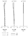
図16は、本発明の実施例4の光学系の無限遠合焦時におけるレンズ構成図である。 FIG. 16 is a lens configuration diagram of the optical system according to Example 4 of the present invention when focusing on infinity.
図16の光学系は、物体側から像面側の順に、全体として正の屈折力を持つ第1レンズ群G1と、全体として正の屈折力を持つ第2レンズ群G2とから構成される。 The optical system of FIG. 16 includes a first lens group G1 having a positive refractive power as a whole and a second lens group G2 having a positive refractive power as a whole in order from the object side to the image plane side.
第1レンズ群G1は、第1レンズ群前群G1Aと第1レンズ群後群G1Bとから成る。また、第1レンズ群G1は、無限遠物体から近距離物体へのフォーカシングに際して像面に対する位置が固定である。 The first lens group G1 includes a first lens group front group G1A and a first lens group rear group G1B. The first lens group G1 is fixed in position with respect to the image plane during focusing from an infinitely distant object to a close object.
第1レンズ群前群G1Aは、物体側に凸面を向けた正メニスカスレンズ及び両凹レンズから構成され、全体として負の屈折力を持つ。 The first lens group front group G1A includes a positive meniscus lens having a convex surface directed toward the object side and a biconcave lens, and has a negative refracting power as a whole.
第1レンズ群後群G1Bは、両凹レンズと両凸レンズから構成され、全体として正の屈折力を持つ。 The first lens group rear group G1B includes a biconcave lens and a biconvex lens, and has a positive refractive power as a whole.
第2レンズ群G2は、第2レンズ群前群G2Aと第2レンズ群後群G2Bとから成り、全体として正の屈折力を持つ。また、第2レンズ群前群G2Aと第2レンズ群後群G2Bは、無限遠物体から近距離物体へのフォーカシングに際して、互いに独立して物体側へ移動する。 The second lens group G2 includes a second lens group front group G2A and a second lens group rear group G2B, and has a positive refractive power as a whole. Further, the second lens group front group G2A and the second lens group rear group G2B move to the object side independently of each other during focusing from an object at infinity to a short distance object.
第2レンズ群前群G2Aは、両凸レンズ、及び両凸レンズ及び両凹レンズから成る負の屈折力を持つ接合レンズで構成され、全体として正の屈折力を持つ。 The second lens group front group G2A is composed of a biconvex lens and a cemented lens having a negative refractive power made up of a biconvex lens and a biconcave lens, and has a positive refractive power as a whole.
開口絞りSは、第2レンズ群前群G2Aと第2レンズ群後群G2Bとの間に配置され、無限遠物体から近距離物体へのフォーカシングに際して、第2レンズ群後群G2Bと同じ軌跡で物体側へ移動する。 The aperture stop S is disposed between the second lens group front group G2A and the second lens group rear group G2B, and has the same locus as the second lens group rear group G2B when focusing from an infinite object to a short distance object. Move to the object side.
第2レンズ群後群G2Bは、両凹レンズと両凸レンズから成る負の屈折力を持つ接合レンズ、両凸レンズと両凹レンズから成る負の屈折力を持つ接合レンズ、及び物体側像面側両面に非球面を形成した両凸レンズから構成され、全体として正の屈折力を持つ。 The second lens group rear group G2B includes a cemented lens having a negative refractive power composed of a biconcave lens and a biconvex lens, a cemented lens having a negative refractive power composed of a biconvex lens and a biconcave lens, and a non-convex lens on both sides of the object side image surface side. It consists of a biconvex lens with a spherical surface, and has positive refractive power as a whole.
続いて、以下に実施例4に係る光学系の諸元値を示す。
数値実施例4
単位:mm
[面データ]
面番号 r d nd vd
物面 ∞ (d0)
1 60.7903 8.8428 2.00100 29.13
2 300.3415 1.9380
3 -2651.9755 2.0000 1.64769 33.84
4 29.0684 13.3974
5 -81.9097 1.5000 1.62588 35.74
6 88.6016 9.0900
7 73.2400 9.0246 1.80420 46.50
8 -83.4926 (d8)
9 47.5968 6.3990 1.95375 32.32
10 -516.1485 0.1981
11 754.2127 4.5821 1.49700 81.61
12 -64.2559 1.9846 1.80518 25.46
13 52.7297 (d13)
14(絞り) ∞ 4.6336
15 -46.9274 1.0000 1.58144 40.89
16 62.9033 4.2357 1.59282 68.62
17 -229.6247 0.1500
18 986.1933 6.8302 1.59282 68.62
19 -26.7075 1.0000 1.51742 52.15
20 92.4851 0.5450
21* 77.1764 7.7735 1.77250 49.47
22* -52.7466 (BF)
像面 ∞
[非球面データ]
21面 22面
K 0.00000 0.00000
A4 -1.05814E-06 4.04323E-06
A6 -3.34540E-09 -5.46959E-09
A8 2.15521E-11 2.71991E-11
A10 0.00000E+00 -2.00988E-15
[各種データ]
INF 398mm
焦点距離 48.50 47.65
Fナンバー 1.46 1.67
全画角2ω 48.25 44.39
像高Y 21.63 21.63
レンズ全長 140.13 140.13
[可変間隔データ]
INF 398mm
d0 ∞ 258.0000
d8 10.5828 1.2000
d13 5.6275 6.7324
BF 38.7999 47.0779
[レンズ群データ]
群 始面 焦点距離
G1 1 272.31
G1A 1 -152.19
G1B 5 112.68
G2A 9 185.34
G2B 14 66.52
Subsequently, specification values of the optical system according to Example 4 are shown below.
Numerical example 4
Unit: mm
[Surface data]
Surface number rd nd vd
Object ∞ (d0)
1 60.7903 8.8428 2.00100 29.13
2 300.3415 1.9380
3 -2651.9755 2.0000 1.64769 33.84
4 29.0684 13.3974
5 -81.9097 1.5000 1.62588 35.74
6 88.6016 9.0900
7 73.2400 9.0246 1.80420 46.50
8 -83.4926 (d8)
9 47.5968 6.3990 1.95375 32.32
10 -516.1485 0.1981
11 754.2127 4.5821 1.49700 81.61
12 -64.2559 1.9846 1.80518 25.46
13 52.7297 (d13)
14 (Aperture) ∞ 4.6336
15 -46.9274 1.0000 1.58144 40.89
16 62.9033 4.2357 1.59282 68.62
17 -229.6247 0.1500
18 986.1933 6.8302 1.59282 68.62
19 -26.7075 1.0000 1.51742 52.15
20 92.4851 0.5450
21 * 77.1764 7.7735 1.77250 49.47
22 * -52.7466 (BF)
Image plane ∞
[Aspherical data]
21 side 22 side
K 0.00000 0.00000
A4 -1.05814E-06 4.04323E-06
A6 -3.34540E-09 -5.46959E-09
A8 2.15521E-11 2.71991E-11
A10 0.00000E + 00 -2.00988E-15
[Various data]
INF 398mm
Focal length 48.50 47.65
F number 1.46 1.67
Full angle of view 2ω 48.25 44.39
Statue height Y 21.63 21.63
Total lens length 140.13 140.13
[Variable interval data]
INF 398mm
d0 ∞ 258.0000
d8 10.5828 1.2000
d13 5.6275 6.7324
BF 38.7999 47.0779
[Lens group data]
Group Start surface Focal length
G1 1 272.31
G1A 1 -152.19
G2A 9 185.34
G2B 14 66.52
図21は、本発明の実施例5の光学系の無限遠合焦時におけるレンズ構成図である。 FIG. 21 is a lens configuration diagram of the optical system according to Example 5 of the present invention when focusing on infinity.
図21の光学系は、物体側から像面側の順に、全体として正の屈折力を持つ第1レンズと、全体として正の屈折力を持つ第2レンズ群G2とから構成される。 The optical system in FIG. 21 includes a first lens having a positive refractive power as a whole and a second lens group G2 having a positive refractive power as a whole in order from the object side to the image plane side.
第1レンズ群G1は、第1レンズ群前群G1Aと第1レンズ群後群G1Bとから成る。また、第1レンズ群G1は、無限遠物体から近距離物体へのフォーカシングに際して像面に対する位置が固定である。 The first lens group G1 includes a first lens group front group G1A and a first lens group rear group G1B. The first lens group G1 is fixed in position with respect to the image plane during focusing from an infinitely distant object to a close object.
第1レンズ群前群G1Aは、物体側に凸面を向けた正メニスカスレンズ及び両凹レンズから構成され、全体として負の屈折力を持つ。 The first lens group front group G1A includes a positive meniscus lens having a convex surface directed toward the object side and a biconcave lens, and has a negative refracting power as a whole.
第1レンズ群後群G1Bは、両凹レンズと両凸レンズから構成され、全体として正の屈折力を持つ。 The first lens group rear group G1B includes a biconcave lens and a biconvex lens, and has a positive refractive power as a whole.
第2レンズ群G2は、第2レンズ群前群G2Aと第2レンズ群後群G2Bとから成り、全体として正の屈折力を持つ。また、第2レンズ群前群G2Aと第2レンズ群後群G2Bは、無限遠物体から近距離物体へのフォーカシングに際して、互いに独立して物体側へ移動する。 The second lens group G2 includes a second lens group front group G2A and a second lens group rear group G2B, and has a positive refractive power as a whole. Further, the second lens group front group G2A and the second lens group rear group G2B move to the object side independently of each other during focusing from an object at infinity to a short distance object.
第2レンズ群前群G2Aは、両凸レンズ、及び両凸レンズと両凹レンズから成る負の屈折力を持つ接合レンズで構成され、全体として正の屈折力を持つ。 The second lens group front group G2A is composed of a biconvex lens and a cemented lens having a negative refractive power composed of a biconvex lens and a biconcave lens, and has a positive refractive power as a whole.
開口絞りSは、第2レンズ群前群G2Aと第2レンズ群後群G2Bとの間に配置され、無限遠物体から近距離物体へのフォーカシングに際して、第2レンズ群後群G2Bと同じ軌跡で物体側へ移動する。 The aperture stop S is disposed between the second lens group front group G2A and the second lens group rear group G2B, and has the same locus as the second lens group rear group G2B when focusing from an infinite object to a short distance object. Move to the object side.
第2レンズ群後群G2Bは、両凹レンズと両凸レンズから成る負の屈折力を持つ接合レンズ、両凸レンズと両凹レンズから成る正の屈折力を持つ接合レンズ、及び物体側像面側両面に非球面を形成した両凸レンズから構成され、全体として正の屈折力を持つ。 The second lens group rear group G2B includes a cemented lens having a negative refractive power composed of a biconcave lens and a biconvex lens, a cemented lens having a positive refractive power composed of a biconvex lens and a biconcave lens, and a non-convex lens on both sides of the object side image surface. It consists of a biconvex lens with a spherical surface, and has positive refractive power as a whole.
続いて、以下に実施例5に係る光学系の諸元値を示す。
数値実施例5
単位:mm
[面データ]
面番号 r d nd vd
物面 ∞ (d0)
1 59.1787 9.1320 1.95375 32.32
2 311.5111 1.9221
3 -2148.9683 2.0000 1.64769 33.84
4 29.0524 13.3413
5 -83.6747 1.6130 1.62588 35.74
6 89.4776 9.1265
7 72.6692 9.0316 1.80420 46.50
8 -84.0466 (d8)
9 46.6909 6.4070 2.00100 29.13
10 -669.2278 0.2934
11 773.5381 4.5435 1.49700 81.61
12 -65.5618 1.0000 1.80518 25.46
13 48.9240 (d13)
14(絞り) ∞ 4.5718
15 -47.4197 1.0000 1.60342 38.01
16 43.9470 4.6019 1.59282 68.62
17 -5000.0000 0.1500
18 193.3916 7.4101 1.59282 68.62
19 -26.2375 1.0000 1.51742 52.15
20 177.2481 0.2905
21* 100.8101 7.0602 1.77250 49.47
22* -52.7466 (BF)
像面 ∞
[非球面データ]
21面 22面
K 0.00000 0.00000
A4 -1.17521E-06 3.97830E-06
A6 -3.24487E-09 -5.63388E-09
A8 2.35948E-11 3.06394E-11
A10 0.00000E+00 -4.71092E-15
[各種データ]
INF 398mm
焦点距離 48.50 47.67
Fナンバー 1.46 1.67
全画角2ω 48.30 44.40
像高Y 21.63 21.63
レンズ全長 139.83 139.83
[可変間隔データ]
INF 398mm
d0 ∞ 258.0000
d8 10.7108 1.2000
d13 5.8214 7.0974
BF 38.7999 47.0347
[レンズ群データ]
群 始面 焦点距離
G1 1 262.98
G1A 1 -149.73
G1B 5 110.03
G2A 9 180.40
G2B 14 67.11
Subsequently, specification values of the optical system according to Example 5 are shown below.
Numerical example 5
Unit: mm
[Surface data]
Surface number rd nd vd
Object ∞ (d0)
1 59.1787 9.1320 1.95375 32.32
2 311.5111 1.9221
3 -2148.9683 2.0000 1.64769 33.84
4 29.0524 13.3413
5 -83.6747 1.6130 1.62588 35.74
6 89.4776 9.1265
7 72.6692 9.0316 1.80420 46.50
8 -84.0466 (d8)
9 46.6909 6.4070 2.00100 29.13
10 -669.2278 0.2934
11 773.5381 4.5435 1.49700 81.61
12 -65.5618 1.0000 1.80518 25.46
13 48.9240 (d13)
14 (Aperture) ∞ 4.5718
15 -47.4197 1.0000 1.60342 38.01
16 43.9470 4.6019 1.59282 68.62
17 -5000.0000 0.1500
18 193.3916 7.4101 1.59282 68.62
19 -26.2375 1.0000 1.51742 52.15
20 177.2481 0.2905
21 * 100.8101 7.0602 1.77250 49.47
22 * -52.7466 (BF)
Image plane ∞
[Aspherical data]
21 side 22 side
K 0.00000 0.00000
A4 -1.17521E-06 3.97830E-06
A6 -3.24487E-09 -5.63388E-09
A8 2.35948E-11 3.06394E-11
A10 0.00000E + 00 -4.71092E-15
[Various data]
INF 398mm
Focal length 48.50 47.67
F number 1.46 1.67
Full angle of view 2ω 48.30 44.40
Statue height Y 21.63 21.63
Total lens length 139.83 139.83
[Variable interval data]
INF 398mm
d0 ∞ 258.0000
d8 10.7108 1.2000
d13 5.8214 7.0974
BF 38.7999 47.0347
[Lens group data]
Group Start surface Focal length
G1 1 262.98
G1A 1 -149.73
G2A 9 180.40
G2B 14 67.11
図26は、本発明の実施例6の光学系の無限遠合焦時におけるレンズ構成図である。 FIG. 26 is a lens configuration diagram of the optical system according to Example 6 of the present invention when focusing on infinity.
図26の光学系は、物体側から像面側の順に、全体として正の屈折力を持つ第1レンズ群G1と、全体として正の屈折力を持つ第2レンズ群G2とから構成される。 The optical system in FIG. 26 includes a first lens group G1 having a positive refractive power as a whole and a second lens group G2 having a positive refractive power as a whole, in order from the object side to the image plane side.
第1レンズ群G1は、第1レンズ群前群G1Aと第1レンズ群後群G1Bとから成る。また、第1レンズ群G1は、無限遠物体から近距離物体へのフォーカシングに際して像面に対する位置が固定である。 The first lens group G1 includes a first lens group front group G1A and a first lens group rear group G1B. The first lens group G1 is fixed in position with respect to the image plane during focusing from an infinitely distant object to a close object.
第1レンズ群前群G1Aは、物体側に凸面を向けた正メニスカスレンズ及び物体側に凸面を向けた負メニスカスレンズから構成され、全体として負の屈折力を持つ。 The first lens group front group G1A includes a positive meniscus lens having a convex surface directed toward the object side and a negative meniscus lens having a convex surface directed toward the object side, and has a negative refracting power as a whole.
第1レンズ群後群G1Bは、物体側に凹面を向けた負メニスカスレンズ、物体側に凹面を向けた正メニスカスレンズ、及び両凸レンズから構成され、全体として正の屈折力を持つ。 The first lens group rear group G1B includes a negative meniscus lens having a concave surface directed toward the object side, a positive meniscus lens having a concave surface directed toward the object side, and a biconvex lens, and has a positive refractive power as a whole.
第2レンズ群G2は、第2レンズ群前群G2Aと第2レンズ群後群G2Bとから成り、全体として正の屈折力を持つ。また、第2レンズ群前群G2Aと第2レンズ群後群G2Bは、無限遠物体から近距離物体へのフォーカシングに際して、互いに独立して物体側へ移動する。 The second lens group G2 includes a second lens group front group G2A and a second lens group rear group G2B, and has a positive refractive power as a whole. Further, the second lens group front group G2A and the second lens group rear group G2B move to the object side independently of each other during focusing from an object at infinity to a short distance object.
第2レンズ群前群G2Aは、両凸レンズ、及び両凸レンズと両凹レンズから成る負の屈折力を持つ接合レンズから構成され、全体として正の屈折力を持つ。 The second lens group front group G2A is composed of a biconvex lens and a cemented lens having a negative refractive power composed of a biconvex lens and a biconcave lens, and has a positive refractive power as a whole.
開口絞りSは、第2レンズ群前群G2Aと第2レンズ群後群G2Bとの間に配置され、無限遠物体から近距離物体へのフォーカシングに際して、第2レンズ群後群G2Bと同じ軌跡で物体側へ移動する。 The aperture stop S is disposed between the second lens group front group G2A and the second lens group rear group G2B, and has the same locus as the second lens group rear group G2B when focusing from an infinite object to a short distance object. Move to the object side.
第2レンズ群後群G2Bは、両凹レンズと両凸レンズから成る負の屈折力を持つ接合レンズ、両凸レンズと像面側に凸面を向けた負メニスカスレンズから成る正の屈折力を持つ接合レンズ、及び物体側像面側両面に非球面を形成した両凸レンズから構成され、全体として正の屈折力を持つ。 The second lens group rear group G2B includes a cemented lens having a negative refractive power composed of a biconcave lens and a biconvex lens, a cemented lens having a positive refractive power composed of a biconvex lens and a negative meniscus lens having a convex surface facing the image surface side, And a biconvex lens having aspheric surfaces on both sides of the object side image surface side, and has a positive refractive power as a whole.
続いて、以下に実施例6に係る光学系の諸元値を示す。
数値実施例6
単位:mm
[面データ]
面番号 r d nd vd
物面 ∞ (d0)
1 60.8145 9.7817 2.00100 29.13
2 961.2391 0.4514
3 1040.2761 2.0000 1.70154 41.15
4 28.6634 15.9911
5 -40.7492 1.5000 1.84666 23.78
6 -565.0365 3.8873
7 -61.9388 5.5803 1.88100 40.14
8 -40.5080 0.1500
9 52.2341 9.0758 1.59282 68.62
10 -149.8277 (d10)
11 52.0046 5.7073 2.00100 29.13
12 -3629.6800 0.1500
13 269.7091 4.8326 1.49700 81.61
14 -69.2869 1.0000 1.64769 33.84
15 43.0996 (d15)
16(絞り) ∞ 5.2887
17 -35.8562 1.0000 1.58144 40.89
18 54.8872 3.9938 1.59282 68.62
19 -1000.0000 0.1500
20 1000.0000 6.8905 1.59282 68.62
21 -25.3861 1.0000 1.58144 40.89
22 -349.2909 0.1500
23* 168.8265 7.4914 1.77250 49.47
24* -42.9103 (BF)
像面 ∞
[非球面データ]
23面 24面
K 0.00000 0.00000
A4 -1.01132E-06 4.20558E-06
A6 -5.37917E-09 -6.54219E-09
A8 2.98408E-11 3.12080E-11
A10 0.00000E+00 -6.26392E-16
[各種データ]
INF 399mm
焦点距離 48.50 47.22
Fナンバー 1.46 1.67
全画角2ω 47.62 44.39
像高Y 21.63 21.63
レンズ全長 141.29 141.29
[可変間隔データ]
INF 399mm
d0 ∞ 258.0000
d10 10.2359 1.2000
d15 6.1802 6.8588
BF 38.8002 47.1575
[レンズ群データ]
群 始面 焦点距離
G1 1 202.73
G1A 1 -173.82
G1B 5 106.30
G2A 11 156.41
G2B 16 73.42
Subsequently, specification values of the optical system according to Example 6 are shown below.
Numerical example 6
Unit: mm
[Surface data]
Surface number rd nd vd
Object ∞ (d0)
1 60.8145 9.7817 2.00100 29.13
2 961.2391 0.4514
3 1040.2761 2.0000 1.70154 41.15
4 28.6634 15.9911
5 -40.7492 1.5000 1.84666 23.78
6 -565.0365 3.8873
7 -61.9388 5.5803 1.88100 40.14
8 -40.5080 0.1500
9 52.2341 9.0758 1.59282 68.62
10 -149.8277 (d10)
11 52.0046 5.7073 2.00100 29.13
12 -3629.6800 0.1500
13 269.7091 4.8326 1.49700 81.61
14 -69.2869 1.0000 1.64769 33.84
15 43.0996 (d15)
16 (Aperture) ∞ 5.2887
17 -35.8562 1.0000 1.58144 40.89
18 54.8872 3.9938 1.59282 68.62
19 -1000.0000 0.1500
20 1000.0000 6.8905 1.59282 68.62
21 -25.3861 1.0000 1.58144 40.89
22 -349.2909 0.1500
23 * 168.8265 7.4914 1.77250 49.47
24 * -42.9103 (BF)
Image plane ∞
[Aspherical data]
23 faces 24 faces
K 0.00000 0.00000
A4 -1.01132E-06 4.20558E-06
A6 -5.37917E-09 -6.54219E-09
A8 2.98408E-11 3.12080E-11
A10 0.00000E + 00 -6.26392E-16
[Various data]
INF 399mm
Focal length 48.50 47.22
F number 1.46 1.67
Full angle of view 2ω 47.62 44.39
Statue height Y 21.63 21.63
Total lens length 141.29 141.29
[Variable interval data]
INF 399mm
d0 ∞ 258.0000
d10 10.2359 1.2000
d15 6.1802 6.8588
BF 38.8002 47.1575
[Lens group data]
Group Start surface Focal length
G1 1 202.73
G1A 1 -173.82
G2A 11 156.41
G2B 16 73.42
図31は、本発明の実施例7の光学系の無限遠合焦時におけるレンズ構成図である。 FIG. 31 is a lens configuration diagram of the optical system according to Example 7 of the present invention when focusing on infinity.
図31の光学系は、物体側から像面側の順に、全体として正の屈折力を持つ第1レンズ群G1と、全体として正の屈折力を持つ第2のレンズ群G2とから構成される。 The optical system of FIG. 31 includes a first lens group G1 having a positive refractive power as a whole and a second lens group G2 having a positive refractive power as a whole in order from the object side to the image plane side. .
第1レンズ群G1は、第1レンズ群前群G1Aと第1レンズ群後群G1Bとから成る。また、第1レンズ群G1は、無限遠物体から近距離物体へのフォーカシングに際して像面に対する位置が固定である。 The first lens group G1 includes a first lens group front group G1A and a first lens group rear group G1B. The first lens group G1 is fixed in position with respect to the image plane during focusing from an infinitely distant object to a close object.
第1レンズ群前群G1Aは、物体側に凸面を向けた正メニスカスレンズ及び物体側に凸面を向けた負メニスカスレンズから構成され、全体として負の屈折力を持つ。 The first lens group front group G1A includes a positive meniscus lens having a convex surface directed toward the object side and a negative meniscus lens having a convex surface directed toward the object side, and has a negative refracting power as a whole.
第1レンズ群後群G1Bは、物体側に凹面を向けた正メニスカスレンズと両凹レンズから成る負の屈折力を持つ接合レンズ、及び両凸レンズから構成される。 The first lens group rear group G1B includes a cemented lens having a negative refractive power and a biconvex lens including a positive meniscus lens having a concave surface directed toward the object side and a biconcave lens.
第2レンズ群G2は、第2レンズ群前群G2Aと第2レンズ群後群G2Bとから成り、全体として正の屈折力を持つ。また、第2レンズ群前群G2Aと第2レンズ群後群G2Bは、無限遠物体から近距離物体へのフォーカシングに際して、互いに独立して物体側へ移動する。 The second lens group G2 includes a second lens group front group G2A and a second lens group rear group G2B, and has a positive refractive power as a whole. Further, the second lens group front group G2A and the second lens group rear group G2B move to the object side independently of each other during focusing from an object at infinity to a short distance object.
第2レンズ群前群G2Aは、両凸レンズと物体側に凹面を向けた正メニスカスレンズと両凹レンズとから成る正の屈折力を持つ3枚接合レンズで構成される。 The second lens group front group G2A is composed of a biconvex lens, a positive meniscus lens having a concave surface directed toward the object side, and a triple-junction lens having positive refractive power and a biconcave lens.
開口絞りSは、第2レンズ群前群G2Aと第2レンズ群後群G2Bとの間に配置され、無限遠物体から近距離物体へのフォーカシングに際して、第2レンズ群後群G2Bと同じ軌跡で物体側へ移動する。 The aperture stop S is disposed between the second lens group front group G2A and the second lens group rear group G2B, and has the same locus as the second lens group rear group G2B when focusing from an infinite object to a short distance object. Move to the object side.
第2レンズ群後群G2Bは、両凹レンズと両凸レンズから成る負の屈折力を持つ接合レンズ、両凹レンズと両凸レンズから成る正の屈折力を持つ接合レンズ、及び物体側像面側両面に非球面を形成した両凸レンズから構成され、全体として正の屈折力を持つ。 The second lens group rear group G2B includes a cemented lens having a negative refractive power composed of a biconcave lens and a biconvex lens, a cemented lens having a positive refractive power composed of a biconcave lens and a biconvex lens, and a non-convex lens on both sides of the object side image surface side. It consists of a biconvex lens with a spherical surface, and has positive refractive power as a whole.
続いて、以下に実施例7に係る光学系の諸元値を示す。
数値実施例7
単位:mm
[面データ]
面番号 r d nd vd
物面 ∞ (d0)
1 61.5553 9.1056 2.00100 29.13
2 416.8509 1.2069
3 2077.2771 2.0000 1.64769 33.84
4 26.5881 14.7728
5 -66.4944 10.0841 1.49700 81.61
6 -26.1053 1.5000 1.60342 38.01
7 266.0512 1.5163
8 80.2575 9.4664 1.80420 46.50
9 -65.4401 (d9)
10 54.7291 6.3242 2.00100 29.13
11 -190.2656 4.9430 1.59282 68.62
12 -43.4725 1.0517 1.64769 33.84
13 50.6721 (d13)
14(絞り) ∞ 4.4632
15 -46.6787 1.0000 1.67270 32.17
16 114.7391 4.7250 1.43700 95.10
17 -56.3927 1.0346
18 -41.7538 1.0000 1.58144 40.89
19 37.9020 6.7490 1.72916 54.67
20 -75.5083 0.1500
21* 1000.0000 6.5783 1.77250 49.47
22* -46.9507 (BF)
像面 ∞
[非球面データ]
21面 22面
K 0.00000 0.00000
A4 -1.59572E-06 3.90584E-06
A6 -4.50908E-09 -5.65822E-09
A8 3.83392E-11 3.86862E-11
A10 0.00000E+00 7.01344E-15
[各種データ]
INF 400mm
焦点距離 48.50 47.20
Fナンバー 1.46 1.67
全画角2ω 47.67 44.48
像高Y 21.63 21.63
レンズ全長 142.00 142.00
[可変間隔データ]
INF 400mm
d0 ∞ 258.0000
d9 9.8338 1.2000
d13 5.6952 5.9008
BF 38.7998 47.2280
[レンズ群データ]
群 始面 焦点距離
G1 1 223.63
G1A 1 -135.14
G1B 5 97.97
G2A 9 123.14
G2B 14 78.83
Subsequently, specification values of the optical system according to Example 7 are shown below.
Numerical example 7
Unit: mm
[Surface data]
Surface number rd nd vd
Object ∞ (d0)
1 61.5553 9.1056 2.00100 29.13
2 416.8509 1.2069
3 2077.2771 2.0000 1.64769 33.84
4 26.5881 14.7728
5 -66.4944 10.0841 1.49700 81.61
6 -26.1053 1.5000 1.60342 38.01
7 266.0512 1.5163
8 80.2575 9.4664 1.80420 46.50
9 -65.4401 (d9)
10 54.7291 6.3242 2.00100 29.13
11 -190.2656 4.9430 1.59282 68.62
12 -43.4725 1.0517 1.64769 33.84
13 50.6721 (d13)
14 (Aperture) ∞ 4.4632
15 -46.6787 1.0000 1.67270 32.17
16 114.7391 4.7250 1.43700 95.10
17 -56.3927 1.0346
18 -41.7538 1.0000 1.58144 40.89
19 37.9020 6.7490 1.72916 54.67
20 -75.5083 0.1500
21 * 1000.0000 6.5783 1.77250 49.47
22 * -46.9507 (BF)
Image plane ∞
[Aspherical data]
21 side 22 side
K 0.00000 0.00000
A4 -1.59572E-06 3.90584E-06
A6 -4.50908E-09 -5.65822E-09
A8 3.83392E-11 3.86862E-11
A10 0.00000E + 00 7.01344E-15
[Various data]
INF 400mm
Focal length 48.50 47.20
F number 1.46 1.67
Full angle of view 2ω 47.67 44.48
Statue height Y 21.63 21.63
Total lens length 142.00 142.00
[Variable interval data]
INF 400mm
d0 ∞ 258.0000
d9 9.8338 1.2000
d13 5.6952 5.9008
BF 38.7998 47.2280
[Lens group data]
Group Start surface Focal length
G1 1 223.63
G1A 1 -135.14
G2A 9 123.14
G2B 14 78.83
図36は、本発明の実施例8の光学系の無限遠合焦時におけるレンズ構成図である。 FIG. 36 is a lens configuration diagram of the optical system according to Example 8 of the present invention when focusing on infinity.
図36の光学系は、物体側から像面側の順に、全体として負の屈折力を持つ第1レンズ群G1と、全体として正の屈折力を持つ第2レンズ群G2とから構成される。 The optical system of FIG. 36 includes a first lens group G1 having a negative refractive power as a whole and a second lens group G2 having a positive refractive power as a whole in order from the object side to the image plane side.
第1レンズ群G1は、第1レンズ群前群G1Aと第1レンズ群後群G1Bとから成る。また、第1レンズ群G1は、無限遠物体から近距離物体へのフォーカシングに際して像面に対する位置が固定である。 The first lens group G1 includes a first lens group front group G1A and a first lens group rear group G1B. The first lens group G1 is fixed in position with respect to the image plane during focusing from an infinitely distant object to a close object.
第1レンズ群前群G1Aは、物体側に凸面を向けた正メニスカスレンズ及び物体側に凸面を向けた負メニスカスレンズから構成され、全体として負の屈折力を持つ。 The first lens group front group G1A includes a positive meniscus lens having a convex surface directed toward the object side and a negative meniscus lens having a convex surface directed toward the object side, and has a negative refracting power as a whole.
第1レンズ群後群G1Bは、物体側に凹面を向けた正メニスカスレンズと両凹レンズと両凸レンズとから成る正の屈折力を持つ3枚接合レンズで構成される。また、第1レンズ群後群G1Bの像面側にフレアカット絞りを設ける。 The first lens group rear group G1B is constituted by a three-piece cemented lens having a positive refractive power, which includes a positive meniscus lens having a concave surface directed toward the object side, a biconcave lens, and a biconvex lens. In addition, a flare cut stop is provided on the image plane side of the first lens group rear group G1B.
第2レンズ群G2は、第2レンズ群前群G2Aと第2レンズ群後群G2Bとから成り、
全体として正の屈折力を持つ。また、第2レンズ群前群G2Aと第2レンズ群後群G2Bは、無限遠物体から近距離物体へのフォーカシングに際して、互いに独立して物体側絵移動する。
The second lens group G2 includes a second lens group front group G2A and a second lens group rear group G2B.
It has a positive refractive power as a whole. In addition, the second lens group front group G2A and the second lens group rear group G2B move the object side picture independently of each other during focusing from an infinite object to a short distance object.
第2レンズ群前群G2Aは、物体側に凸面を向けた正メニスカスレンズ、及び両凸レンズと両凹レンズから成る負の屈折力を持つ接合レンズで構成され、全体として正の屈折力を持つ。 The second lens group front group G2A includes a positive meniscus lens having a convex surface directed toward the object side, and a cemented lens having a negative refractive power including a biconvex lens and a biconcave lens, and has a positive refractive power as a whole.
開口絞りSは、第2レンズ群前群G2Aと第2レンズ群後群G2Bとの間に配置され、無限遠物体から近距離物体へのフォーカシングに際して、第2レンズ郡後群G2Bと同じ軌跡で物体側へ移動する。 The aperture stop S is disposed between the second lens group front group G2A and the second lens group rear group G2B, and has the same trajectory as the second lens group rear group G2B when focusing from an infinite object to a short distance object. Move to the object side.
第2レンズ群後群G2Bは、両凹レンズと両凸レンズから成る負の屈折力を持つ接合レンズ、両凸レンズと像面側に凸面を向けた負メニスカスレンズから成る正の屈折力を持つ接合レンズ、及び物体側像面側両面に非球面を形成した両凸レンズから構成され、全体として正の屈折力を持つ。 The second lens group rear group G2B includes a cemented lens having a negative refractive power composed of a biconcave lens and a biconvex lens, a cemented lens having a positive refractive power composed of a biconvex lens and a negative meniscus lens having a convex surface facing the image surface side, And a biconvex lens having aspheric surfaces on both sides of the object side image surface side, and has a positive refractive power as a whole.
続いて、以下に実施例8に係る光学系の諸元値を示す。
数値実施例8
単位:mm
[面データ]
面番号 r d nd vd
物面 ∞ (d0)
1 68.6980 5.5111 1.95375 32.32
2 140.4190 0.4000
3 90.0805 2.0000 1.59551 39.22
4 28.0310 17.4906
5 -57.6273 11.4150 1.59282 68.62
6 -24.7074 1.4000 1.62588 35.74
7 43.6599 10.7365 1.88300 40.81
8 -95.6712 0.0000
9(フレアカット絞り) ∞ (d9)
10 57.2684 4.4674 1.92286 20.88
11 247.3667 0.1500
12 39.3575 7.5133 1.72916 54.67
13 -842.9948 0.9500 1.64769 33.84
14 27.3663 (d14)
15(絞り) ∞ 5.3318
16 -32.3508 0.9000 1.64769 33.84
17 41.2236 5.0135 1.59282 68.62
18 -469.6114 0.1500
19 186.8195 6.9513 1.59282 68.62
20 -27.7493 0.9000 1.58144 40.89
21 -106.1094 0.1500
22* 338.5122 5.3034 1.77250 49.47
23* -44.4036 (BF)
像面 ∞
[非球面データ]
22面 23面
K 0.00000 0.00000
A4 -2.02470E-06 2.15920E-06
A6 7.06100E-12 -9.75660E-10
A8 -4.96280E-13 1.51180E-12
A10 2.34710E-15 0.00000E+00
[各種データ]
INF 400mm
焦点距離 47.17 46.51
Fナンバー 1.46 1.69
全画角2ω 49.24 45.33
像高Y 21.63 21.63
レンズ全長 142.00 142.00
[可変間隔データ]
INF 400mm
d0 ∞ 258.0000
d9 8.2225 1.2000
d14 8.2436 6.6132
BF 38.8001 47.4530
[レンズ群データ]
群 始面 焦点距離
G1 1 -12811.28
G1A 1 -158.83
G1B 5 202.30
G2A 10 89.30
G2B 15 73.81
Subsequently, specification values of the optical system according to Example 8 are shown below.
Numerical example 8
Unit: mm
[Surface data]
Surface number rd nd vd
Object ∞ (d0)
1 68.6980 5.5111 1.95375 32.32
2 140.4190 0.4000
3 90.0805 2.0000 1.59551 39.22
4 28.0310 17.4906
5 -57.6273 11.4150 1.59282 68.62
6 -24.7074 1.4000 1.62588 35.74
7 43.6599 10.7365 1.88300 40.81
8 -95.6712 0.0000
9 (Flare cut aperture) ∞ (d9)
10 57.2684 4.4674 1.92286 20.88
11 247.3667 0.1500
12 39.3575 7.5133 1.72916 54.67
13 -842.9948 0.9500 1.64769 33.84
14 27.3663 (d14)
15 (Aperture) ∞ 5.3318
16 -32.3508 0.9000 1.64769 33.84
17 41.2236 5.0135 1.59282 68.62
18 -469.6114 0.1500
19 186.8195 6.9513 1.59282 68.62
20 -27.7493 0.9000 1.58144 40.89
21 -106.1094 0.1500
22 * 338.5122 5.3034 1.77250 49.47
23 * -44.4036 (BF)
Image plane ∞
[Aspherical data]
22 faces 23 faces
K 0.00000 0.00000
A4 -2.02470E-06 2.15920E-06
A6 7.06100E-12 -9.75660E-10
A8 -4.96280E-13 1.51180E-12
A10 2.34710E-15 0.00000E + 00
[Various data]
INF 400mm
Focal length 47.17 46.51
F number 1.46 1.69
Full angle of view 2ω 49.24 45.33
Statue height Y 21.63 21.63
Total lens length 142.00 142.00
[Variable interval data]
INF 400mm
d0 ∞ 258.0000
d9 8.2225 1.2000
d14 8.2436 6.6132
BF 38.8001 47.4530
[Lens group data]
Group Start surface Focal length
G1 1 -12811.28
G1A 1 -158.83
G2A 10 89.30
G2B 15 73.81
また、これらの各実施例における条件式の対応値の一覧を示す。
[条件式対応値]
条件式/実施例 1 2 3 4
(1) 1.50<|R1br/R1ar|<6.0 3.28 3.07 2.64 2.87
(2) 0.35<T/f<0.55 0.46 0.49 0.49 0.40
(3) 0.50<|f/R1bf|<1.50 0.73 0.80 0.83 0.59
(4) 1.80<nd2p 1.92 1.92 2.00 1.95
(5) 0.50<|R2bf/R2ar|<1.5 1.01 0.99 0.88 0.89
(6) 0.20<|f/f1a|<0.50 0.32 0.32 0.28 0.32
(7) 0.20<f/f1b<0.60 0.43 0.31 0.37 0.43
(8) 0.20<f/f2a<0.60 0.29 0.44 0.29 0.26
(9) 0.50<f/f2b<1.00 0.76 0.66 0.72 0.73
条件式/実施例 5 6 7 8
(1) 1.50<|R1br/R1ar|<6.0 2.89 5.23 2.46 3.41
(2) 0.35<T/f<0.55 0.41 0.42 0.47 0.50
(3) 0.50<|f/R1bf|<1.50 0.58 1.19 0.73 0.82
(4) 1.80<nd2p 2.00 2.00 2.00 1.92
(5) 0.50<|R2bf/R2ar|<1.5 0.97 0.83 0.92 1.18
(6) 0.20<|f/f1a|<0.50 0.32 0.28 0.36 0.30
(7) 0.20<f/f1b<0.60 0.44 0.46 0.50 0.23
(8) 0.20<f/f2a<0.60 0.27 0.31 0.39 0.53
(9) 0.50<f/f2b<1.00 0.72 0.66 0.62 0.64
In addition, a list of corresponding values of conditional expressions in each of these examples is shown.
[Values for conditional expressions]
Conditional expression / Example 1 2 3 4
(1) 1.50 <| R1br / R1ar | <6.0 3.28 3.07 2.64 2.87
(2) 0.35 <T / f <0.55 0.46 0.49 0.49 0.40
(3) 0.50 <| f / R1bf | <1.50 0.73 0.80 0.83 0.59
(4) 1.80 <nd2p 1.92 1.92 2.00 1.95
(5) 0.50 <| R2bf / R2ar | <1.5 1.01 0.99 0.88 0.89
(6) 0.20 <| f / f1a | <0.50 0.32 0.32 0.28 0.32
(7) 0.20 <f / f1b <0.60 0.43 0.31 0.37 0.43
(8) 0.20 <f / f2a <0.60 0.29 0.44 0.29 0.26
(9) 0.50 <f / f2b <1.00 0.76 0.66 0.72 0.73
Conditional expression / Example 5 6 7 8
(1) 1.50 <| R1br / R1ar | <6.0 2.89 5.23 2.46 3.41
(2) 0.35 <T / f <0.55 0.41 0.42 0.47 0.50
(3) 0.50 <| f / R1bf | <1.50 0.58 1.19 0.73 0.82
(4) 1.80 <nd2p 2.00 2.00 2.00 1.92
(5) 0.50 <| R2bf / R2ar | <1.5 0.97 0.83 0.92 1.18
(6) 0.20 <| f / f1a | <0.50 0.32 0.28 0.36 0.30
(7) 0.20 <f / f1b <0.60 0.44 0.46 0.50 0.23
(8) 0.20 <f / f2a <0.60 0.27 0.31 0.39 0.53
(9) 0.50 <f / f2b <1.00 0.72 0.66 0.62 0.64
G1 第1レンズ群
G2 第2レンズ群
G1A 第1レンズ群前群
G1B 第1レンズ群後群
G2A 第2レンズ群前群
G2B 第2レンズ群後群
S 開口絞り
I 像面
d d線
C C線
g g線
F Fナンバー
△S サジタル像面
△M メリジオナル像面
G1 First lens group G2 Second lens group G1A First lens group front group G1B First lens group rear group G2A Second lens group front group G2B Second lens group rear group S Aperture stop I Image surface d d line C C line g g line F F number △ S sagittal image surface △ M meridional image surface
Claims (4)
前記第1レンズ群G1は、物体側から像面側の順に、前記第1レンズ群G1の中で最も長い光軸上の空気間隔を隔てて、負の屈折力を持つ第1レンズ群前群G1Aと正の屈折力を持つ第1レンズ群後群G1Bとからなり、
前記第1レンズ群前群G1Aの最も像面側の光学面は、像面側に凹面を向けており、
前記第1レンズ群後群G1Bの最も物体側の光学面は、物体側に凹面を向けており、
前記第1レンズ群後群G1Bの最も像面側の光学面は、像面側に凸面を向けており、
前記第2レンズ群G2は、物体側から像面側の順に、正の屈折力を持つ第2レンズ群前群G2Aと正の屈折力を持つ第2レンズ群後群G2Bとからなり、
無限遠物体から近距離物体へのフォーカシングに際して、前記第2レンズ群G2を光軸に沿って像面側から物体側へ移動し、以下に示す条件式(1)乃至(3)を満足することを特徴とする光学系。
(1) 1.50<|R1br/R1ar|<6.00
(2) 0.35<T/f<0.55
(3) 0.50<|f/R1bf|<1.50
f :無限遠物体合焦時における光学系全系の焦点距離
R1ar:前記第1レンズ群前群G1Aの最も像面側の光学面の曲率半径
R1bf:前記第1レンズ群後群G1Bの最も物体側の光学面の曲率半径
R1br:前記第1レンズ群後群G1Bの最も像面側の光学面の曲率半径
T :前記第1レンズ群後群G1Bの最も物体側の光学面から前記第1レンズ群後群G1Bの最も像側の光学面までの光軸上の距離
In order from the object side to the image plane side, the first lens group G1 and a second lens group G2 having a positive refractive power,
The first lens group G1 has a negative refractive power and a first lens group front group having a negative refractive power in order from the object side to the image plane side with the longest air interval on the optical axis in the first lens group G1. G1A and the first lens unit rear group G1B having a positive refractive power,
The optical surface closest to the image plane of the first lens group front group G1A has a concave surface facing the image plane side,
The most object side optical surface of the first lens group rear group G1B has a concave surface facing the object side,
The optical surface closest to the image plane of the first lens group rear group G1B has a convex surface facing the image plane side,
The second lens group G2 includes, in order from the object side to the image plane side, a second lens group front group G2A having a positive refractive power and a second lens group rear group G2B having a positive refractive power.
When focusing from an infinitely distant object to a close object, the second lens group G2 is moved from the image plane side to the object side along the optical axis, and the following conditional expressions (1) to (3) are satisfied. An optical system characterized by
(1) 1.50 <| R1br / R1ar | <6.00
(2) 0.35 <T / f <0.55
(3) 0.50 <| f / R1bf | <1.50
f: Focal length R1ar of the entire optical system at the time of focusing on an object at infinity: Radius of curvature R1bf of the optical surface closest to the image plane of the first lens group front group G1A: Most object of the first lens group rear group G1B Radius of curvature R1br of the optical surface on the side: curvature radius T of the optical surface closest to the image plane of the first lens group rear group G1B: the first lens from the optical surface closest to the object side of the rear group G1B of the first lens group The distance on the optical axis to the most image side optical surface of the rear group G1B
The first lens group front group G1A has a lens having a positive refractive power with a convex surface facing the object side on the most object side, and the first lens group rear group G1B is on the most image side. The optical system according to claim 1, further comprising a lens having a positive refractive power.
(4) 1.80<nd2p
(5) 0.50<|R2bf/R2ar|<1.50
nd2p:前記第2レンズ群前群G2Aの最も屈折率の高い正の屈折力を持つレンズの屈折率
R2ar:前記第2レンズ群前群G2Aの最も像側の光学面の曲率半径
R2bf:前記第2レンズ群後群G2Bの最も物体側の光学面の曲率半径
The second lens group front group G2A and the second lens group rear group G2B are separated by the longest air space on the optical axis in the second lens group G2, and the following conditional expressions (4) to (4) The optical system according to claim 1, wherein 5) is satisfied.
(4) 1.80 <nd2p
(5) 0.50 <| R2bf / R2ar | <1.50
nd2p: refractive index R2ar of the lens having positive refractive power with the highest refractive index of the second lens group front group G2A: radius of curvature R2bf of the optical surface closest to the image side of the second lens group front group G2A: The radius of curvature of the optical surface closest to the object side in the two-lens group rear group G2B
(6) 0.20<|f/f1a|<0.50
(7) 0.20<f/f1b<0.60
(8) 0.20<f/f2a<0.60
(9) 0.50<f/f2b<1.00
f1a:前記第1レンズ群前群G1Aの焦点距離
f1b:前記第1レンズ群後群G1Bの焦点距離
f2a:前記第2レンズ群前群G2Aの焦点距離
f2b:前記第2レンズ群後群G2Bの焦点距離 The optical system according to any one of claims 1 to 3, wherein the following conditional expressions (6) to (8) are satisfied.
(6) 0.20 <| f / f1a | <0.50
(7) 0.20 <f / f1b <0.60
(8) 0.20 <f / f2a <0.60
(9) 0.50 <f / f2b <1.00
f1a: focal length of the first lens group front group G1A f1b: focal length of the first lens group rear group G1B f2a: focal length of the second lens group front group G2A f2b: of the second lens group rear group G2B Focal length
Priority Applications (1)
| Application Number | Priority Date | Filing Date | Title |
|---|---|---|---|
| JP2013254099A JP6219699B2 (en) | 2013-12-09 | 2013-12-09 | Optical system |
Applications Claiming Priority (1)
| Application Number | Priority Date | Filing Date | Title |
|---|---|---|---|
| JP2013254099A JP6219699B2 (en) | 2013-12-09 | 2013-12-09 | Optical system |
Publications (2)
| Publication Number | Publication Date |
|---|---|
| JP2015114366A true JP2015114366A (en) | 2015-06-22 |
| JP6219699B2 JP6219699B2 (en) | 2017-10-25 |
Family
ID=53528244
Family Applications (1)
| Application Number | Title | Priority Date | Filing Date |
|---|---|---|---|
| JP2013254099A Active JP6219699B2 (en) | 2013-12-09 | 2013-12-09 | Optical system |
Country Status (1)
| Country | Link |
|---|---|
| JP (1) | JP6219699B2 (en) |
Cited By (10)
| Publication number | Priority date | Publication date | Assignee | Title |
|---|---|---|---|---|
| JP2015146015A (en) * | 2014-01-06 | 2015-08-13 | パナソニックIpマネジメント株式会社 | Single focus lens system, interchangeable lens device, and camera system |
| JP2016161650A (en) * | 2015-02-27 | 2016-09-05 | 株式会社タムロン | Optical system and imaging device |
| JP2017078835A (en) * | 2015-10-22 | 2017-04-27 | 株式会社ニコン | Photographic lens, optical apparatus provided with photographic lens, and method of manufacturing photographic lens |
| JP2018005099A (en) * | 2016-07-07 | 2018-01-11 | 株式会社シグマ | Large-aperture lens |
| JP2019049646A (en) * | 2017-09-11 | 2019-03-28 | キヤノン株式会社 | Optical system and imaging apparatus having the same |
| JP2019066585A (en) * | 2017-09-29 | 2019-04-25 | キヤノン株式会社 | Single focus lens and imaging device |
| JP2019139158A (en) * | 2018-02-14 | 2019-08-22 | 株式会社リコー | Image capturing lens system and image capturing device |
| JP2021076740A (en) * | 2019-11-11 | 2021-05-20 | 株式会社コシナ | Large diameter imaging optical system |
| CN112882197A (en) * | 2016-12-28 | 2021-06-01 | 三星电机株式会社 | Optical imaging system |
| JP2023179306A (en) * | 2022-06-07 | 2023-12-19 | 株式会社シグマ | single focus lens |
Citations (4)
| Publication number | Priority date | Publication date | Assignee | Title |
|---|---|---|---|---|
| JPS5849734A (en) * | 1982-09-06 | 1983-03-24 | Matsushita Electric Ind Co Ltd | Flame-retardant resin composition for electric insulation |
| US5703726A (en) * | 1995-08-28 | 1997-12-30 | Eastman Kodak Company | Reverse telephoto lens |
| JP2007225804A (en) * | 2006-02-22 | 2007-09-06 | Mamiya Digital Imaging Co Ltd | Retrofocus type superwide angle lens |
| JP2014048359A (en) * | 2012-08-30 | 2014-03-17 | Olympus Imaging Corp | Imaging optical system and imaging apparatus including the same |
-
2013
- 2013-12-09 JP JP2013254099A patent/JP6219699B2/en active Active
Patent Citations (4)
| Publication number | Priority date | Publication date | Assignee | Title |
|---|---|---|---|---|
| JPS5849734A (en) * | 1982-09-06 | 1983-03-24 | Matsushita Electric Ind Co Ltd | Flame-retardant resin composition for electric insulation |
| US5703726A (en) * | 1995-08-28 | 1997-12-30 | Eastman Kodak Company | Reverse telephoto lens |
| JP2007225804A (en) * | 2006-02-22 | 2007-09-06 | Mamiya Digital Imaging Co Ltd | Retrofocus type superwide angle lens |
| JP2014048359A (en) * | 2012-08-30 | 2014-03-17 | Olympus Imaging Corp | Imaging optical system and imaging apparatus including the same |
Cited By (19)
| Publication number | Priority date | Publication date | Assignee | Title |
|---|---|---|---|---|
| JP2015146015A (en) * | 2014-01-06 | 2015-08-13 | パナソニックIpマネジメント株式会社 | Single focus lens system, interchangeable lens device, and camera system |
| JP2016161650A (en) * | 2015-02-27 | 2016-09-05 | 株式会社タムロン | Optical system and imaging device |
| JP2017078835A (en) * | 2015-10-22 | 2017-04-27 | 株式会社ニコン | Photographic lens, optical apparatus provided with photographic lens, and method of manufacturing photographic lens |
| JP2018005099A (en) * | 2016-07-07 | 2018-01-11 | 株式会社シグマ | Large-aperture lens |
| US12092798B2 (en) | 2016-12-28 | 2024-09-17 | Samsung Electro-Mechanics Co., Ltd. | Optical imaging system |
| US11635594B2 (en) | 2016-12-28 | 2023-04-25 | Samsung Electro-Mechanics Co., Ltd. | Optical imaging system |
| CN112882197A (en) * | 2016-12-28 | 2021-06-01 | 三星电机株式会社 | Optical imaging system |
| JP2019049646A (en) * | 2017-09-11 | 2019-03-28 | キヤノン株式会社 | Optical system and imaging apparatus having the same |
| US11016274B2 (en) | 2017-09-29 | 2021-05-25 | Canon Kabushiki Kaisha | Fixed focal length lens and image pickup apparatus |
| JP2019066585A (en) * | 2017-09-29 | 2019-04-25 | キヤノン株式会社 | Single focus lens and imaging device |
| JP7035592B2 (en) | 2018-02-14 | 2022-03-15 | 株式会社リコー | Shooting lens system and image pickup device |
| US11397309B2 (en) | 2018-02-14 | 2022-07-26 | Ricoh Company, Ltd. | Imaging lens system and imaging apparatus incorporating the same |
| US20220291481A1 (en) * | 2018-02-14 | 2022-09-15 | Ricoh Company, Ltd. | Imaging lens system and imaging apparatus incorporating the same |
| JP2019139158A (en) * | 2018-02-14 | 2019-08-22 | 株式会社リコー | Image capturing lens system and image capturing device |
| US11934036B2 (en) | 2018-02-14 | 2024-03-19 | Ricoh Company, Ltd. | Imaging lens system and imaging apparatus incorporating the same |
| JP2021076740A (en) * | 2019-11-11 | 2021-05-20 | 株式会社コシナ | Large diameter imaging optical system |
| JP7514503B2 (en) | 2019-11-11 | 2024-07-11 | 株式会社コシナ | Large aperture imaging optical system |
| JP2023179306A (en) * | 2022-06-07 | 2023-12-19 | 株式会社シグマ | single focus lens |
| JP7823879B2 (en) | 2022-06-07 | 2026-03-04 | 株式会社シグマ | Single focal length lens |
Also Published As
| Publication number | Publication date |
|---|---|
| JP6219699B2 (en) | 2017-10-25 |
Similar Documents
| Publication | Publication Date | Title |
|---|---|---|
| JP6219699B2 (en) | Optical system | |
| US8503110B2 (en) | Lens system, wide-angle lens, optical apparatus equipped with lens system, and method for manufacturing lens system | |
| US7982965B2 (en) | Zoom lens, optical apparatus equipped therewith and method for manufacturing the zoom lens | |
| JP5495800B2 (en) | Optical system and imaging apparatus having the same | |
| US7903348B2 (en) | Rear-focus optical system, imaging apparatus and method for focusing the same | |
| JP5729431B2 (en) | Imaging optical system, camera device, and portable information terminal device | |
| JP5455572B2 (en) | Zoom lens and imaging apparatus having the same | |
| US8107174B2 (en) | Wide-angle lens, imaging apparatus, and method for manufacturing wide-angle lens | |
| US8369021B2 (en) | Zoom lens system, optical apparatus equipped therewith, and method for zooming zoom lens system | |
| US8970968B2 (en) | Photographing lens system | |
| US20090153980A1 (en) | Macro lens, optical apparatus, and method for manufacturing the macro lens | |
| WO2015146067A1 (en) | Zoom-lens system, interchangeable-lens device, and camera system | |
| JP2004334185A (en) | Zoom lens | |
| JP6046504B2 (en) | Imaging lens system | |
| JP6749632B2 (en) | Large aperture lens | |
| CN105308491A (en) | Fixed-focal-length lens system | |
| JP6665615B2 (en) | Large aperture telephoto lens | |
| US20250244566A1 (en) | Zoom lens | |
| JP2019191502A (en) | Inner-focus image capturing lens and image capturing device | |
| JP2007206420A (en) | Zoom lens and image projection apparatus having the same | |
| US9001441B2 (en) | Imaging lens, optical apparatus equipped therewith, and method for manufacturing imaging lens | |
| JP2018045097A (en) | Zoom lens | |
| JP5854944B2 (en) | Inner focus lens | |
| JP2006065026A (en) | Zoom lens and image projection apparatus having the same | |
| JP4601328B2 (en) | Zoom optical system and imaging apparatus using the same |
Legal Events
| Date | Code | Title | Description |
|---|---|---|---|
| A621 | Written request for application examination |
Free format text: JAPANESE INTERMEDIATE CODE: A621 Effective date: 20160609 |
|
| A977 | Report on retrieval |
Free format text: JAPANESE INTERMEDIATE CODE: A971007 Effective date: 20170420 |
|
| A131 | Notification of reasons for refusal |
Free format text: JAPANESE INTERMEDIATE CODE: A131 Effective date: 20170530 |
|
| A521 | Request for written amendment filed |
Free format text: JAPANESE INTERMEDIATE CODE: A523 Effective date: 20170622 |
|
| TRDD | Decision of grant or rejection written | ||
| A01 | Written decision to grant a patent or to grant a registration (utility model) |
Free format text: JAPANESE INTERMEDIATE CODE: A01 Effective date: 20170926 |
|
| A61 | First payment of annual fees (during grant procedure) |
Free format text: JAPANESE INTERMEDIATE CODE: A61 Effective date: 20170928 |
|
| R150 | Certificate of patent or registration of utility model |
Ref document number: 6219699 Country of ref document: JP Free format text: JAPANESE INTERMEDIATE CODE: R150 |
|
| R250 | Receipt of annual fees |
Free format text: JAPANESE INTERMEDIATE CODE: R250 |
|
| R250 | Receipt of annual fees |
Free format text: JAPANESE INTERMEDIATE CODE: R250 |
|
| R250 | Receipt of annual fees |
Free format text: JAPANESE INTERMEDIATE CODE: R250 |
|
| R250 | Receipt of annual fees |
Free format text: JAPANESE INTERMEDIATE CODE: R250 |
|
| R250 | Receipt of annual fees |
Free format text: JAPANESE INTERMEDIATE CODE: R250 |
|
| R250 | Receipt of annual fees |
Free format text: JAPANESE INTERMEDIATE CODE: R250 |