JP2015114359A - Lens drive device - Google Patents
Lens drive device Download PDFInfo
- Publication number
- JP2015114359A JP2015114359A JP2013253959A JP2013253959A JP2015114359A JP 2015114359 A JP2015114359 A JP 2015114359A JP 2013253959 A JP2013253959 A JP 2013253959A JP 2013253959 A JP2013253959 A JP 2013253959A JP 2015114359 A JP2015114359 A JP 2015114359A
- Authority
- JP
- Japan
- Prior art keywords
- frame member
- lens
- driving
- lens frame
- magnet
- Prior art date
- Legal status (The legal status is an assumption and is not a legal conclusion. Google has not performed a legal analysis and makes no representation as to the accuracy of the status listed.)
- Granted
Links
Images


Landscapes
- Lens Barrels (AREA)
- Studio Devices (AREA)
- Reciprocating, Oscillating Or Vibrating Motors (AREA)
Abstract
【課題】レンズ駆動装置の始動電流を低くして電源の消費電力を抑えること、レンズ枠部材の最大ストロークを含む大きな駆動ストロークを得るための駆動電力を抑える。【解決手段】レンズ駆動装置1は、光軸方向に移動自在なレンズ枠部材11と、レンズ枠部材11を移動自在に保持する枠部材12と、枠部材12を支持するベース部材15と、レンズ枠部材11に固定されるマグネット13Aと枠部材12に固定されるコイル13Bを備えレンズ枠部材11を光軸方向に駆動する駆動手段13とを備え、マグネット13Aの移動方向延長位置に、マグネット13Aに吸着力を作用させる磁性体3を支持する。【選択図】図1The power consumption of a power source is reduced by reducing the starting current of a lens driving device, and the driving power for obtaining a large driving stroke including the maximum stroke of a lens frame member is suppressed. A lens driving device includes a lens frame member that is movable in an optical axis direction, a frame member that holds the lens frame member in a movable manner, a base member that supports the frame member, a lens, A magnet 13A that is fixed to the frame member 11 and a coil 13B that is fixed to the frame member 12 are provided, and a driving means 13 that drives the lens frame member 11 in the optical axis direction is provided. The magnetic body 3 that causes an attractive force to act on is supported. [Selection] Figure 1
Description
本発明は、レンズ駆動装置、カメラモジュール、電子機器などに関するものである。 The present invention relates to a lens driving device, a camera module, an electronic device, and the like.
コイルとマグネットを駆動手段として備える電磁駆動式のレンズ駆動装置が知られている(下記特許文献1参照)。このレンズ駆動装置は、レンズの光軸に沿って移動自在なレンズ枠部材と、このレンズ枠部材を移動自在に保持する枠部材と、レンズ枠部材に設けたコイルと枠部材に設けたマグネットによってレンズ枠部材を光軸方向に駆動する駆動手段を設けている。また、このような従来のレンズ駆動装置は、レンズ枠部材の移動を光軸方向に沿って弾性的に規制する弾性規制部材(板バネ)を備えており、この弾性規制部材の弾性力と前述した駆動手段の駆動力が釣り合う位置でレンズの光軸方向の位置を可変調整している。 An electromagnetically driven lens driving device including a coil and a magnet as driving means is known (see Patent Document 1 below). The lens driving device includes a lens frame member that is movable along the optical axis of the lens, a frame member that holds the lens frame member movably, a coil provided on the lens frame member, and a magnet provided on the frame member. Driving means for driving the lens frame member in the optical axis direction is provided. Further, such a conventional lens driving device includes an elastic restricting member (plate spring) that elastically restricts the movement of the lens frame member along the optical axis direction. The position of the lens in the optical axis direction is variably adjusted at a position where the driving force of the driving means is balanced.
このようなレンズ駆動装置は、弾性規制部材によって規制された初期位置に静止しているレンズ枠部材を始動させる際の始動電流が大きいことで、電源の消費電力が大きくなる問題がある。また、コイルに供給する駆動電流とレンズ枠部材の駆動ストロークの関係が直線的な比例関係になっておらず、駆動ストロークが大きくなるに連れて直線的な比例関係より駆動電流が大きくなる傾向がある。このため、大きな駆動ストロークを得るための駆動電流、とりわけレンズ枠部材の駆動ストロークを最大ストロークにするために必要な駆動電流が大きくなる問題があった。 Such a lens driving device has a problem that the power consumption of the power source increases due to a large starting current when starting the lens frame member stationary at the initial position regulated by the elastic regulating member. In addition, the relationship between the driving current supplied to the coil and the driving stroke of the lens frame member is not linearly proportional, and as the driving stroke increases, the driving current tends to increase from the linear proportional relationship. is there. For this reason, there has been a problem that a drive current for obtaining a large drive stroke, particularly a drive current necessary for setting the drive stroke of the lens frame member to the maximum stroke is increased.
本発明は、このような問題に対処することを課題の一例とするものである。すなわち、レンズ駆動装置の始動電流を低くして電源の消費電力を低く抑えること、レンズ枠部材の最大ストロークを含む大きな駆動ストロークを得るための駆動電流を低く抑えること、等が本発明の目的である。 This invention makes it an example of a subject to cope with such a problem. That is, it is an object of the present invention to reduce the power consumption of the power source by lowering the starting current of the lens driving device, and to keep the driving current for obtaining a large driving stroke including the maximum stroke of the lens frame member low. is there.
このような目的を達成するために、本発明によるレンズ駆動装置は、明細書に記載された幾つかの発明のうち以下の構成を具備するものである。
光軸方向に移動自在なレンズ枠部材と、前記レンズ枠部材を移動自在に保持する枠部材と、前記枠部材を支持するベース部材と、前記レンズ枠部材に固定されるマグネットと前記枠部材に固定されるコイルを備え前記レンズ枠部材を光軸方向に駆動する駆動手段とを備え、前記マグネットの移動方向延長位置に、当該マグネットに吸着力を作用させる磁性体を支持することを特徴とするレンズ駆動装置。
In order to achieve such an object, a lens driving device according to the present invention comprises the following configurations among several inventions described in the specification.
A lens frame member movable in the optical axis direction, a frame member holding the lens frame member movably, a base member supporting the frame member, a magnet fixed to the lens frame member, and the frame member And a driving means for driving the lens frame member in the optical axis direction with a fixed coil, and supporting a magnetic body that applies an attractive force to the magnet at an extended position in the moving direction of the magnet. Lens drive device.
本発明の実施形態に係るレンズ駆動装置は、レンズ枠部材、枠部材、ベース部材、駆動手段を備える。駆動手段は、光軸方向に移動自在なレンズ枠部材にマグネットを固定し、レンズ枠部材を移動自在に保持する枠部材にコイルを固定したムービングマグネット方式である。そして、本発明の実施形態に係るレンズ駆動装置は、駆動手段のマグネットの移動方向延長位置に、マグネットに吸着力を作用させる磁性体を支持している。このようなレンズ駆動装置は、駆動手段の駆動力(ローレンツ力)をアシストするようにマグネットと磁性体の吸着力が作用する。これによって、レンズ枠部材を駆動するための始動電流を低く抑えることができると共に、最大ストローク時の駆動電流を低く抑えることができる。また、レンズ枠部材が規定ストロークに到達するためのストロークと駆動電流の関係を直線的な比例関係に近づけることができるので、オートフォーカスなどでのレンズ枠部材の位置制御が容易になる。 A lens driving device according to an embodiment of the present invention includes a lens frame member, a frame member, a base member, and driving means. The driving means is a moving magnet type in which a magnet is fixed to a lens frame member movable in the optical axis direction, and a coil is fixed to a frame member that holds the lens frame member movably. In the lens driving device according to the embodiment of the present invention, a magnetic body that applies an attractive force to the magnet is supported at an extension position in the moving direction of the magnet of the driving means. In such a lens driving device, the attractive force of the magnet and the magnetic material acts so as to assist the driving force (Lorentz force) of the driving means. As a result, the starting current for driving the lens frame member can be kept low, and the driving current during the maximum stroke can be kept low. Further, since the relationship between the stroke for the lens frame member to reach the specified stroke and the drive current can be brought close to a linear proportional relationship, the position control of the lens frame member in autofocusing or the like is facilitated.
このようなレンズ駆動装置にシャッタ装置を加えたカメラモジュールにおいては、シャッタ装置のシャッタ駆動手段に用いられるヨークを前述した磁性体として機能させることができる。すなわち、レンズ駆動装置のマグネットの移動方向延長位置にシャッタ駆動手段のヨークを配備する。これによって、レンズ枠部材を駆動する駆動手段の駆動力(ローレンツ力)をアシストするようにマグネットとヨークの吸着力が作用するので、カメラモジュールにおいて、レンズ枠部材を駆動するための始動電流や最大ストローク時の駆動電流を低く抑えることができると共に、レンズ枠部材が規定ストロークに到達するためのストロークと駆動電流の関係を直線的な比例関係に近づけることができる。 In a camera module in which a shutter device is added to such a lens driving device, the yoke used for the shutter driving means of the shutter device can function as the magnetic material described above. That is, the yoke of the shutter driving means is arranged at the extended position in the moving direction of the magnet of the lens driving device. As a result, the attracting force between the magnet and the yoke acts so as to assist the driving force (Lorentz force) of the driving means for driving the lens frame member. Therefore, in the camera module, the starting current for driving the lens frame member and the maximum The driving current during the stroke can be kept low, and the relationship between the stroke and the driving current for the lens frame member to reach the specified stroke can be made closer to a linear proportional relationship.
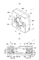
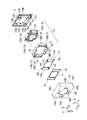
以下、本発明の実施形態を図面を参照して説明する。図1及び図2は本発明の一実施形態に係るレンズ駆動装置を示している(図1(a)が全体斜視図、図1(b)が図1(a)におけるX−X断面図、図2が分解図)。レンズ駆動装置1は、レンズ駆動部10(レンズ枠部材11、枠部材12、駆動手段13)がベース部材15上に組み付けられた構造をなしている。レンズ枠部材11は図示省略したレンズバレルが装着されてレンズの光軸方向に移動自在な部材である。枠部材12はレンズ枠部材11を移動自在に保持する部材であり、具体的には、レンズ枠部材11の周囲に配置され、2つの弾性規制部材14を介してレンズ枠部材11を光軸方向に移動自在に保持している。駆動手段13は、レンズ枠部材11に固定されるマグネット13Aと枠部材12に固定されるコイル13Bを備え、レンズ枠部材11を光軸に沿って駆動する駆動力を発生するものである。
Hereinafter, embodiments of the present invention will be described with reference to the drawings. 1 and 2 show a lens driving device according to an embodiment of the present invention (FIG. 1 (a) is an overall perspective view, FIG. 1 (b) is an XX cross-sectional view in FIG. 1 (a), FIG. 2 is an exploded view). The lens driving device 1 has a structure in which a lens driving unit 10 (
ベース部材15は、中央に開口部15Aを備えており、枠部材12を支持する支持部15Bを備えている。また、ベース部材15は、駆動手段13の無通電時にレンズ枠部材11が当接する当接部15Cが開口部15Aの周りに設けられ、駆動手段13の無通電時にレンズ枠部材11が光軸と交差する方向に移動するのを規制する移動規制部15Dが複数箇所に設けられている。
The
弾性規制部材14は、枠部材12における光軸方向の一端側に取り付けられる外側取付部14Aと、レンズ枠部材11における光軸方向の一端側に取り付けられる内側取付部14Bと、外側取付部14Aと内側取付部14Bを連結する弾性変形部14Cを備えている。図示の例では、レンズ枠部材11の保持に一対の弾性規制部材14が用いられており、一対の外側取付部14Aが枠部材12の光軸方向一端側と他端側にそれぞれ取り付けられ、一対の内側取付部14Bがレンズ枠部材11の光軸方向一端側と他端側にそれぞれ取り付けられている。外側取付部14Aを枠部材12の一端側に取り付ける際には押さえ部材16が用いられ、内側取付部14Bをレンズ枠部材11に一端側に取り付けるには押さえ部材17が用いられている。
The elastic regulating
レンズ駆動装置1は、駆動手段13のコイル13Bに通電することでマグネット13Aとそれを固定したレンズ枠部材11を光軸方向に移動させるが、このマグネット13Aの移動方向延長位置に、マグネット13Aに吸着力を作用させる磁性体3を支持している。磁性体3の支持には各種の支持構造を採用することができるが、図示の例では、磁性体3は、レンズ枠部材11と枠部材12を覆うカバー部材18に支持されている。カバー部材18は、ベース部材15の外縁に支持される側壁部18Aと天板部18Bを備えており、天板部18Bには、レンズ枠部材11のレンズ装置口に対応する開口18Cが形成されている。磁性体3は、レンズ枠部材11の周囲に固定されたマグネット13Aの移動方向延長位置であり、天板部18Bにおける開口18Cを囲む位置に支持凹部18Dを設け、その中に支持される。
The lens driving device 1 moves the
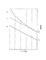
図3は、本発明の実施形態に係るレンズ駆動装置の駆動特性を示した説明図であり、駆動電流とレンズ枠部材の駆動ストロークの関係を示したグラフである。図における実線aが磁性体3を備えた本発明の実施形態に係るレンズ駆動装置1の駆動特性を示しており、図における一点破線bが磁性体3を備えていないレンズ駆動装置の駆動特性を示している。また、図における破線cが、駆動電流と駆動ストロークの関係の理論値を示している。
FIG. 3 is an explanatory diagram showing the driving characteristics of the lens driving device according to the embodiment of the present invention, and is a graph showing the relationship between the driving current and the driving stroke of the lens frame member. The solid line a in the figure shows the driving characteristic of the lens driving device 1 according to the embodiment of the present invention having the
図3に示すように、磁性体3を備えていないレンズ駆動装置は、比較的始動電流E0が高く、駆動ストロークを大きくしていくと、駆動電流が理論値より大きくなる傾向がある。その原因は、マグネット13Aの移動によってコイル13Bを通過する磁束密度が低下することや、レンズ枠部材11の移動を弾性的に規制する弾性規制部材14の弾性力が駆動ストロークが大きくなるにつれて比例的な増加を示さなくなることなどが考えられる。
As shown in FIG. 3, the lens driving device that does not include the
これに対して、磁性体3を備えるレンズ駆動装置1は、図3に示すように、磁性体3を備えない場合の始動電流E0に対して始動電流E1を低くすることができ、更に、駆動電流と駆動ストロークの関係を直線的な比例関係に補正することができる。これは、コイル13Bに駆動電流を流すことによって生じる駆動力(ローレンツ力)に、マグネット13Aに磁性体3が吸着される力が加わって、レンズ枠部材11を光軸方向に移動する推力になるからであり、このような吸着力による駆動力のアシスト効果によって、始動電流E1の低下と駆動特性の改善が実現されている。
On the other hand, the lens driving device 1 including the
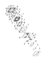
図4及び図5は、本発明の他の実施形態を示した説明図であって、前述した磁性体の吸着力による駆動力のアシスト効果を有するカメラモジュールを示している(図4(a)がカメラモジュールの平面図、図4(b)がそのA−A断面図、図5がその分解図である。前述した説明と同一部位には同一符号を付して重複説明を一部省略する)。 4 and 5 are explanatory views showing another embodiment of the present invention, and show a camera module having an assisting effect of driving force by the above-mentioned magnetic body attracting force (FIG. 4A). 4A is a plan view of the camera module, Fig. 4B is a cross-sectional view thereof taken along the line AA, and Fig. 5 is an exploded view thereof. ).
このカメラモジュール4は、レンズ駆動装置1Aとシャッタ駆動装置2を具備しており、レンズ駆動装置1Aの光軸方向に載置するようにシャッタ駆動装置2を配備している。レンズ駆動装置1Aは、前述したレンズ駆動装置1と同様の基本構成を備えるものであり、ベース部材15にレンズ駆動部10が支持されており、レンズ枠部材11が一対の弾性規制部材14を介して枠部材12に保持されている。
The
シャッタ駆動装置2は、レンズ駆動装置1Aのカバー部材18の上に載置される地板20、地板20に設置されるシャッタ駆動手段21、仕切り板26、レンズ枠部材11のレンズ開口を開放・遮蔽するシャッタ部材27、カバー板28を備えている。そして、シャッタ駆動手段21は、ロータマグネット22、ヨーク23、コイル24、ボビン25によって構成されている。ここで、カメラモジュール4は、シャッタ駆動手段21のヨーク23を前述した磁性体3として機能させている。すなわち、シャッタ駆動手段21のヨーク23をレンズ駆動装置1Aのマグネット13Aの移動方向延長位置に配備している。
The shutter drive device 2 opens and shields the
このようなカメラモジュール4は、レンズ駆動装置1Aの駆動力アシスト用の磁性体を別途設けることが無く、シャッタ駆動装置2のシャッタ駆動手段21におけるヨーク23を利用して、吸着力による駆動力のアシスト効果を実現している。図示の例では、レンズ枠部材11に固定される4つのマグネット13Aのうち、対向位置にある2つのマグネット13Aに対してその移動方向延長位置にヨーク23を配備しているが、吸着力による駆動力のアシスト効果を更に高めるためには、他の2つのマグネット13Aの移動方向延長位置になるように地板20に別途磁性体を配備してもよい。
Such a
このようなレンズ駆動装置1又はカメラモジュール4は、磁性体3或いはヨーク23とマグネット13Aとの吸着力によってレンズ枠部材11を駆動する駆動力をアシストすることができるので、レンズ駆動装置1(1A)の始動電流を低くして電源の消費電力を抑えることができ、また、レンズ枠部材11の最大ストロークを含む大きな駆動ストロークを得る際の駆動電流を低く抑えることが可能になる。また、レンズ駆動装置1(1A)における駆動電流と駆動ストロークの関係を直線的な比例関係に補正することができるので、フォーカス制御などにおけるレンズ枠部材11の位置制御を駆動電流によって簡易に制御することが可能になる。
Since the lens driving device 1 or the
また、このようなレンズ駆動装置1やカメラモジュール4は、図6に示すような電子機器100(携帯電話、スマートフォン、タブレット端末、携帯カメラなど)に搭載することで、消費電力を抑え、精度の高いレンズ位置制御が可能な電子機器100を得ることができる。
In addition, the lens driving device 1 and the
以上、本発明の実施の形態について図面を参照して詳述してきたが、具体的な構成はこれらの実施の形態に限られるものではなく、本発明の要旨を逸脱しない範囲の設計の変更等があっても本発明に含まれる。また、上述の各実施の形態は、その目的及び構成等に特に矛盾や問題がない限り、互いの技術を流用して組み合わせることが可能である。 As described above, the embodiments of the present invention have been described in detail with reference to the drawings. However, the specific configuration is not limited to these embodiments, and the design can be changed without departing from the scope of the present invention. Is included in the present invention. In addition, the above-described embodiments can be combined by utilizing each other's technology as long as there is no particular contradiction or problem in the purpose and configuration.
1,1A:レンズ駆動装置,10:レンズ駆動部,11:レンズ駆動部材,
12:枠部材,13:駆動手段,13A:マグネット,13B:コイル,
14:弾性規制部材,
14A:外側取付部,14B:内側取付部,14C:弾性変形部,
15:ベース部材,
15A:開口部,15B:支持部,15C:当接部,15D:移動規制部,
16,17:押さえ部材,18:カバー部材,
2:シャッタ駆動装置,20:地板,21:シャッタ駆動手段,
22:ロータマグネット,23:ヨーク,24:コイル,25:ボビン,
26:仕切り板,27:シャッタ部材,28:カバー板
1, 1A: Lens drive device, 10: Lens drive unit, 11: Lens drive member,
12: Frame member, 13: Driving means, 13A: Magnet, 13B: Coil,
14: Elastic regulating member,
14A: outer mounting portion, 14B: inner mounting portion, 14C: elastic deformation portion,
15: Base member,
15A: Opening part, 15B: Support part, 15C: Contact part, 15D: Movement restricting part,
16, 17: holding member, 18: cover member,
2: shutter driving device, 20: ground plane, 21: shutter driving means,
22: rotor magnet, 23: yoke, 24: coil, 25: bobbin,
26: partition plate, 27: shutter member, 28: cover plate
Claims (5)
前記レンズ枠部材を移動自在に保持する枠部材と、
前記枠部材を支持するベース部材と、
前記レンズ枠部材に固定されるマグネットと前記枠部材に固定されるコイルを備え前記レンズ枠部材を光軸方向に駆動する駆動手段とを備え、
前記マグネットの移動方向延長位置に、当該マグネットに吸着力を作用させる磁性体を支持することを特徴とするレンズ駆動装置。 A lens frame member movable in the optical axis direction;
A frame member for movably holding the lens frame member;
A base member that supports the frame member;
Comprising a magnet fixed to the lens frame member and a coil fixed to the frame member, and driving means for driving the lens frame member in the optical axis direction;
A lens driving device characterized by supporting a magnetic body that applies an attractive force to the magnet at an extended position in the moving direction of the magnet.
シャッタ部材と該シャッタ部材を駆動するシャッタ駆動手段とを備えたシャッタ駆動装置とを具備し、
前記マグネットの移動方向延長位置に前記シャッタ駆動手段のヨークを配備したことを特徴とするカメラモジュール。 A lens frame member movable in the optical axis direction, a frame member holding the lens frame member movably, a base member supporting the frame member, a magnet fixed to the lens frame member, and the frame member A lens driving device including a coil to be fixed, and a driving means for driving the lens frame member in the optical axis direction;
A shutter driving device including a shutter member and shutter driving means for driving the shutter member;
A camera module, wherein a yoke of the shutter driving means is arranged at an extended position in the moving direction of the magnet.
Priority Applications (1)
| Application Number | Priority Date | Filing Date | Title |
|---|---|---|---|
| JP2013253959A JP6429456B2 (en) | 2013-12-09 | 2013-12-09 | Camera module and electronic device |
Applications Claiming Priority (1)
| Application Number | Priority Date | Filing Date | Title |
|---|---|---|---|
| JP2013253959A JP6429456B2 (en) | 2013-12-09 | 2013-12-09 | Camera module and electronic device |
Publications (2)
| Publication Number | Publication Date |
|---|---|
| JP2015114359A true JP2015114359A (en) | 2015-06-22 |
| JP6429456B2 JP6429456B2 (en) | 2018-11-28 |
Family
ID=53528238
Family Applications (1)
| Application Number | Title | Priority Date | Filing Date |
|---|---|---|---|
| JP2013253959A Active JP6429456B2 (en) | 2013-12-09 | 2013-12-09 | Camera module and electronic device |
Country Status (1)
| Country | Link |
|---|---|
| JP (1) | JP6429456B2 (en) |
Cited By (1)
| Publication number | Priority date | Publication date | Assignee | Title |
|---|---|---|---|---|
| WO2016006239A1 (en) * | 2014-07-11 | 2016-01-14 | ミツミ電機株式会社 | Lens driving device, camera module, and camera-equipped portable terminal |
Citations (12)
| Publication number | Priority date | Publication date | Assignee | Title |
|---|---|---|---|---|
| WO2005036251A1 (en) * | 2003-10-14 | 2005-04-21 | Nidec Copal Corporation | Portable information terminal with camera |
| JP2005107084A (en) * | 2003-09-30 | 2005-04-21 | Sankyo Seiki Mfg Co Ltd | Manufacturing method of lens driving device |
| JP2005309076A (en) * | 2004-04-21 | 2005-11-04 | Sankyo Seiki Mfg Co Ltd | Lens drive device |
| JP2006276565A (en) * | 2005-03-30 | 2006-10-12 | Sumida Corporation | Lens drive device |
| WO2006118180A1 (en) * | 2005-04-28 | 2006-11-09 | Nidec Copal Corporation | Imaging device and portable information terminal device |
| JP2007174222A (en) * | 2005-12-21 | 2007-07-05 | Mitsumi Electric Co Ltd | The camera module |
| JP2007310242A (en) * | 2006-05-19 | 2007-11-29 | Nidec Sankyo Corp | Lens drive unit |
| JP2008076451A (en) * | 2006-09-19 | 2008-04-03 | Citizen Holdings Co Ltd | Shutter device and camera module |
| JP2008116901A (en) * | 2006-10-10 | 2008-05-22 | Nidec Sankyo Corp | Lens drive unit |
| JP2010079271A (en) * | 2008-08-28 | 2010-04-08 | Sharp Corp | Camera module and electronic device including the same |
| JP2010204509A (en) * | 2009-03-05 | 2010-09-16 | Nidec Sankyo Corp | Lens drive device |
| JP2013190654A (en) * | 2012-03-14 | 2013-09-26 | Alps Electric Co Ltd | Lens drive device |
-
2013
- 2013-12-09 JP JP2013253959A patent/JP6429456B2/en active Active
Patent Citations (12)
| Publication number | Priority date | Publication date | Assignee | Title |
|---|---|---|---|---|
| JP2005107084A (en) * | 2003-09-30 | 2005-04-21 | Sankyo Seiki Mfg Co Ltd | Manufacturing method of lens driving device |
| WO2005036251A1 (en) * | 2003-10-14 | 2005-04-21 | Nidec Copal Corporation | Portable information terminal with camera |
| JP2005309076A (en) * | 2004-04-21 | 2005-11-04 | Sankyo Seiki Mfg Co Ltd | Lens drive device |
| JP2006276565A (en) * | 2005-03-30 | 2006-10-12 | Sumida Corporation | Lens drive device |
| WO2006118180A1 (en) * | 2005-04-28 | 2006-11-09 | Nidec Copal Corporation | Imaging device and portable information terminal device |
| JP2007174222A (en) * | 2005-12-21 | 2007-07-05 | Mitsumi Electric Co Ltd | The camera module |
| JP2007310242A (en) * | 2006-05-19 | 2007-11-29 | Nidec Sankyo Corp | Lens drive unit |
| JP2008076451A (en) * | 2006-09-19 | 2008-04-03 | Citizen Holdings Co Ltd | Shutter device and camera module |
| JP2008116901A (en) * | 2006-10-10 | 2008-05-22 | Nidec Sankyo Corp | Lens drive unit |
| JP2010079271A (en) * | 2008-08-28 | 2010-04-08 | Sharp Corp | Camera module and electronic device including the same |
| JP2010204509A (en) * | 2009-03-05 | 2010-09-16 | Nidec Sankyo Corp | Lens drive device |
| JP2013190654A (en) * | 2012-03-14 | 2013-09-26 | Alps Electric Co Ltd | Lens drive device |
Cited By (3)
| Publication number | Priority date | Publication date | Assignee | Title |
|---|---|---|---|---|
| WO2016006239A1 (en) * | 2014-07-11 | 2016-01-14 | ミツミ電機株式会社 | Lens driving device, camera module, and camera-equipped portable terminal |
| JP2016020939A (en) * | 2014-07-11 | 2016-02-04 | ミツミ電機株式会社 | Lens driving device, camera module, and mobile terminal with camera |
| US10401589B2 (en) | 2014-07-11 | 2019-09-03 | Mitsumi Electric Co., Ltd. | Lens driving device, camera module, and camera-equipped portable terminal |
Also Published As
| Publication number | Publication date |
|---|---|
| JP6429456B2 (en) | 2018-11-28 |
Similar Documents
| Publication | Publication Date | Title |
|---|---|---|
| US11768422B2 (en) | Voice coil motor | |
| JP6601638B2 (en) | Lens drive device, autofocus camera and camera-equipped mobile terminal device | |
| CN102798959B (en) | Voice coil motor structure capable of realizing controllable inclination of lens | |
| JP6273491B2 (en) | Lens driving device, camera device, and electronic device | |
| JP6187906B2 (en) | Lens driving device, camera device, and electronic device | |
| JP5201587B2 (en) | Lens drive device | |
| JP2004184779A (en) | Lens driving device | |
| JP2006195452A (en) | Focus adjustment apparatus with improved vibration and impact-resistance properties | |
| KR20200123599A (en) | Actuator for camera and camera module including it | |
| WO2007026830A1 (en) | Lens drive device | |
| JP2021509967A (en) | Drive mechanism, camera module and electronic equipment | |
| JP2015191213A (en) | Lens drive device | |
| JP2011065114A (en) | Lens driving device, autofocus camera, and cellular phone equipped with camera | |
| JP2015055794A (en) | Drive device and blur correction device | |
| WO2021147769A1 (en) | Vibration apparatus and electronic device | |
| JP2012234136A (en) | Lens drive device, autofocus camera, and portable terminal device | |
| US20160291284A1 (en) | Lens-driving device | |
| KR20210010033A (en) | Actuator for camera | |
| JP6429456B2 (en) | Camera module and electronic device | |
| JP2017207785A (en) | Shake correction device | |
| JP2016014702A (en) | Lens driving device | |
| KR101668605B1 (en) | Camera actuator for portable device | |
| JP2013238764A (en) | Magnetic circuit for lens drive device | |
| JP7176145B1 (en) | Imaging devices and portable electronic devices | |
| JP7290781B1 (en) | Imaging devices and portable electronic devices |
Legal Events
| Date | Code | Title | Description |
|---|---|---|---|
| A621 | Written request for application examination |
Free format text: JAPANESE INTERMEDIATE CODE: A621 Effective date: 20160316 |
|
| A977 | Report on retrieval |
Free format text: JAPANESE INTERMEDIATE CODE: A971007 Effective date: 20161207 |
|
| A131 | Notification of reasons for refusal |
Free format text: JAPANESE INTERMEDIATE CODE: A131 Effective date: 20161220 |
|
| A521 | Request for written amendment filed |
Free format text: JAPANESE INTERMEDIATE CODE: A523 Effective date: 20170220 |
|
| A02 | Decision of refusal |
Free format text: JAPANESE INTERMEDIATE CODE: A02 Effective date: 20170725 |
|
| A521 | Request for written amendment filed |
Free format text: JAPANESE INTERMEDIATE CODE: A523 Effective date: 20171019 |
|
| A911 | Transfer to examiner for re-examination before appeal (zenchi) |
Free format text: JAPANESE INTERMEDIATE CODE: A911 Effective date: 20171026 |
|
| A912 | Re-examination (zenchi) completed and case transferred to appeal board |
Free format text: JAPANESE INTERMEDIATE CODE: A912 Effective date: 20180105 |
|
| A521 | Request for written amendment filed |
Free format text: JAPANESE INTERMEDIATE CODE: A523 Effective date: 20180801 |
|
| A61 | First payment of annual fees (during grant procedure) |
Free format text: JAPANESE INTERMEDIATE CODE: A61 Effective date: 20181030 |
|
| R150 | Certificate of patent or registration of utility model |
Ref document number: 6429456 Country of ref document: JP Free format text: JAPANESE INTERMEDIATE CODE: R150 |
|
| R250 | Receipt of annual fees |
Free format text: JAPANESE INTERMEDIATE CODE: R250 |
|
| R250 | Receipt of annual fees |
Free format text: JAPANESE INTERMEDIATE CODE: R250 |