JP2015114307A - Image processing apparatus, image processing method, and imaging apparatus - Google Patents
Image processing apparatus, image processing method, and imaging apparatus Download PDFInfo
- Publication number
- JP2015114307A JP2015114307A JP2013259075A JP2013259075A JP2015114307A JP 2015114307 A JP2015114307 A JP 2015114307A JP 2013259075 A JP2013259075 A JP 2013259075A JP 2013259075 A JP2013259075 A JP 2013259075A JP 2015114307 A JP2015114307 A JP 2015114307A
- Authority
- JP
- Japan
- Prior art keywords
- image
- unit
- imaging unit
- polarization
- pixel
- Prior art date
- Legal status (The legal status is an assumption and is not a legal conclusion. Google has not performed a legal analysis and makes no representation as to the accuracy of the status listed.)
- Pending
Links
Images
Classifications
-
- H—ELECTRICITY
- H04—ELECTRIC COMMUNICATION TECHNIQUE
- H04N—PICTORIAL COMMUNICATION, e.g. TELEVISION
- H04N13/00—Stereoscopic video systems; Multi-view video systems; Details thereof
- H04N13/20—Image signal generators
- H04N13/271—Image signal generators wherein the generated image signals comprise depth maps or disparity maps
-
- G—PHYSICS
- G01—MEASURING; TESTING
- G01B—MEASURING LENGTH, THICKNESS OR SIMILAR LINEAR DIMENSIONS; MEASURING ANGLES; MEASURING AREAS; MEASURING IRREGULARITIES OF SURFACES OR CONTOURS
- G01B11/00—Measuring arrangements characterised by the use of optical techniques
- G01B11/24—Measuring arrangements characterised by the use of optical techniques for measuring contours or curvatures
-
- G—PHYSICS
- G01—MEASURING; TESTING
- G01C—MEASURING DISTANCES, LEVELS OR BEARINGS; SURVEYING; NAVIGATION; GYROSCOPIC INSTRUMENTS; PHOTOGRAMMETRY OR VIDEOGRAMMETRY
- G01C11/00—Photogrammetry or videogrammetry, e.g. stereogrammetry; Photographic surveying
- G01C11/04—Interpretation of pictures
- G01C11/30—Interpretation of pictures by triangulation
-
- G—PHYSICS
- G01—MEASURING; TESTING
- G01C—MEASURING DISTANCES, LEVELS OR BEARINGS; SURVEYING; NAVIGATION; GYROSCOPIC INSTRUMENTS; PHOTOGRAMMETRY OR VIDEOGRAMMETRY
- G01C3/00—Measuring distances in line of sight; Optical rangefinders
- G01C3/02—Details
- G01C3/06—Use of electric means to obtain final indication
- G01C3/08—Use of electric radiation detectors
-
- G—PHYSICS
- G06—COMPUTING OR CALCULATING; COUNTING
- G06T—IMAGE DATA PROCESSING OR GENERATION, IN GENERAL
- G06T7/00—Image analysis
- G06T7/50—Depth or shape recovery
- G06T7/55—Depth or shape recovery from multiple images
-
- H—ELECTRICITY
- H04—ELECTRIC COMMUNICATION TECHNIQUE
- H04N—PICTORIAL COMMUNICATION, e.g. TELEVISION
- H04N13/00—Stereoscopic video systems; Multi-view video systems; Details thereof
- H04N13/20—Image signal generators
- H04N13/204—Image signal generators using stereoscopic image cameras
- H04N13/239—Image signal generators using stereoscopic image cameras using two two-dimensional [2D] image sensors having a relative position equal to or related to the interocular distance
-
- H—ELECTRICITY
- H04—ELECTRIC COMMUNICATION TECHNIQUE
- H04N—PICTORIAL COMMUNICATION, e.g. TELEVISION
- H04N13/00—Stereoscopic video systems; Multi-view video systems; Details thereof
- H04N13/20—Image signal generators
- H04N13/204—Image signal generators using stereoscopic image cameras
- H04N13/25—Image signal generators using stereoscopic image cameras using two or more image sensors with different characteristics other than in their location or field of view, e.g. having different resolutions or colour pickup characteristics; using image signals from one sensor to control the characteristics of another sensor
-
- H—ELECTRICITY
- H04—ELECTRIC COMMUNICATION TECHNIQUE
- H04N—PICTORIAL COMMUNICATION, e.g. TELEVISION
- H04N13/00—Stereoscopic video systems; Multi-view video systems; Details thereof
- H04N13/10—Processing, recording or transmission of stereoscopic or multi-view image signals
- H04N13/106—Processing image signals
- H04N13/128—Adjusting depth or disparity
-
- H—ELECTRICITY
- H04—ELECTRIC COMMUNICATION TECHNIQUE
- H04N—PICTORIAL COMMUNICATION, e.g. TELEVISION
- H04N13/00—Stereoscopic video systems; Multi-view video systems; Details thereof
- H04N2013/0074—Stereoscopic image analysis
- H04N2013/0081—Depth or disparity estimation from stereoscopic image signals
Landscapes
- Engineering & Computer Science (AREA)
- Physics & Mathematics (AREA)
- General Physics & Mathematics (AREA)
- Multimedia (AREA)
- Signal Processing (AREA)
- Radar, Positioning & Navigation (AREA)
- Remote Sensing (AREA)
- Electromagnetism (AREA)
- Computer Vision & Pattern Recognition (AREA)
- Theoretical Computer Science (AREA)
- Measurement Of Optical Distance (AREA)
- Studio Devices (AREA)
- Image Processing (AREA)
- Testing, Inspecting, Measuring Of Stereoscopic Televisions And Televisions (AREA)
- Length Measuring Devices By Optical Means (AREA)
Abstract
Description
この技術は、画像処理装置と画像処理方法および撮像装置に関し、高精度のデプスマップを生成しつつ、画素数の減らない画像を取得できるようにする。 This technology relates to an image processing device, an image processing method, and an imaging device, and enables generation of an image in which the number of pixels is not reduced while generating a highly accurate depth map.
近年、3Dプリンタの低価格化等に伴い、3次元形状を手軽に取得する手段が求められている。 In recent years, with the price reduction of 3D printers and the like, a means for easily acquiring a three-dimensional shape is required.
被写体の3次元形状を取得する手段としては、アクティブ方式とパッシブ方式が存在する。アクティブ方式は、例えば光を被写体に照射して、被写体からの反射光に基づき3次元形状を取得する方式であり、消費電力や部品コスト等から手軽な方式ではない。このアクティブ方式に対してパッシブ方式は、被写体に光を照射することなく3次元形状を取得する方式であり、アクティブ方式に比べて手軽な方式である。パッシブ方式では、例えばステレオカメラを用いて画像間の対応を求めることでデプスマップを生成する手法や、複数の方向の偏光画像を取得して法線マップを生成する手法が用いられている。 As means for acquiring the three-dimensional shape of the subject, there are an active method and a passive method. The active method is a method in which, for example, a subject is irradiated with light and a three-dimensional shape is acquired based on reflected light from the subject, and is not a simple method due to power consumption, component costs, and the like. In contrast to the active method, the passive method is a method for acquiring a three-dimensional shape without irradiating the subject with light, and is a simple method compared to the active method. In the passive method, for example, a method of generating a depth map by obtaining a correspondence between images using a stereo camera, or a method of generating a normal map by acquiring polarized images in a plurality of directions is used.
パッシブ方式において、ステレオカメラを用いる手法では被写体の平坦部のデプスが取得できないという問題が知られている。また、複数の方向の偏光画像を用いる手法では、被写体の相対的な表面形状は取得できるが絶対的な距離を取得できないことが知られている。さらに、複数の方向の偏光画像を用いる手法では、被写体の法線の方位角に180度の不定性があることが知られている。そこで、特許文献1では、ステレオカメラの個々のカメラに搭載されているイメージセンサの各画素に偏光方向の異なる偏光フィルタを配置することで、ステレオカメラによるデプスマップの取得と偏光イメージングによる法線マップの取得を同時に行う。さらに、特許文献1では、デプスマップを参照することで法線マップの持つ180度の不定性の解決および絶対的な距離の取得が可能とされている。
In the passive method, there is a known problem that the depth of the flat part of the subject cannot be acquired by the method using the stereo camera. Further, it is known that a method using polarized images in a plurality of directions can acquire a relative surface shape of a subject but cannot acquire an absolute distance. Furthermore, it is known that the method using polarization images in a plurality of directions has an indefiniteness of 180 degrees in the azimuth angle of the normal line of the subject. Therefore, in
ところで、特許文献1は、4つの画素を画像単位として、この4つの画素に偏光方向が異なる偏光子をそれぞれ設ける構成を用いている。したがって、このような構成では、特定の偏光方向の偏光画像の画素数は元々のイメージセンサの画素数の(1/4)となってしまい、高精度のデプスマップを生成することができない。また,画素数が減ることで通常の画像としての品質も低下する。
By the way,
そこで、この技術では、高精度のデプスマップを生成しつつ、画素数の減らない画像を取得できる画像処理装置と画像処理方法および撮像装置を提供することを目的とする。 Accordingly, an object of the present technology is to provide an image processing apparatus, an image processing method, and an imaging apparatus that can acquire an image whose number of pixels is not reduced while generating a highly accurate depth map.
この技術の第1の側面は、偏光方向が異なる画素を含む画素構成の第1の撮像部によって生成された第1の画像と、前記第1の撮像部と画素構成が異なる第2の撮像部によって生成された第2の画像とを用いたマッチング処理によって、デプスマップを生成するデプスマップ生成部と、前記デプスマップ生成部により生成された第1の画像または第2の画像の少なくとも何れかの偏光画像の偏光状態に基づいて法線マップを生成する法線マップ生成部と、前記デプスマップ生成部で生成されたデプスマップと前記法線マップ生成部で生成された法線マップの統合処理を行うマップ統合部とを有する画像処理装置にある。 A first aspect of this technology is a first image generated by a first imaging unit having a pixel configuration including pixels having different polarization directions, and a second imaging unit having a pixel configuration different from that of the first imaging unit. A depth map generating unit that generates a depth map by a matching process using the second image generated by the first image, and at least one of the first image and the second image generated by the depth map generating unit A normal map generating unit that generates a normal map based on a polarization state of a polarization image; and a process of integrating the depth map generated by the depth map generating unit and the normal map generated by the normal map generating unit. And an image processing apparatus having a map integration unit.
この技術では、偏光方向が異なる画素を含む画素構成の第1の撮像部によって生成された第1の画像と、第1の撮像部と画素構成が異なる第2の撮像部によって生成された第2の画像とを用いてマッチング処理によってデプスマップが生成される。例えば第1の画像は、偏光方向が3方向以上の画素を含む第1の撮像部によって生成された画像であり、第2の画像は、偏光特性を持たない画素で構成された第2の撮像部によって生成された画像である場合、第1の画像から無偏光画像が生成されて、この無偏光画像と第2の画像のそれぞれのエッジ抽出画像を用いてマッチング処理が行われる。 In this technique, a first image generated by a first imaging unit having a pixel configuration including pixels having different polarization directions, and a second image generated by a second imaging unit having a pixel configuration different from that of the first imaging unit. A depth map is generated by a matching process using the images. For example, the first image is an image generated by a first imaging unit including pixels whose polarization directions are three or more, and the second image is a second imaging composed of pixels having no polarization characteristics. In the case of the image generated by the unit, a non-polarized image is generated from the first image, and matching processing is performed using the edge extracted images of the non-polarized image and the second image.
第1の画像は、偏光特性を有した画素からなる第1の画素群と、第1の画素群と異なる偏光方向の画素または偏光特性を持たない画素からなる第2の画素群とで構成された画素構成の第1の撮像部で生成された画像であり、第2の画像は、第1の画素群と対応する位置で偏光方向が第1の画像とは異なる偏光方向の画素からなる第3の画素群と、第2の画素群と対応する位置で第2の画素群と等しい偏光方向の画素または偏光特性を持たない画素からなる第4の画素群とで構成された画素構成の第2の撮像部で生成された画像である場合、第1の画像における第2の画素群の画像と、第2の画像における第4画素群の画像とを用いることにより、偏光方向が等しい画像間または偏光特性を持たない画像間でマッチング処理が行われる。 The first image is composed of a first pixel group composed of pixels having polarization characteristics and a second pixel group composed of pixels having a polarization direction different from that of the first pixel group or pixels having no polarization characteristics. The second image is an image generated by the first imaging unit having the pixel configuration described above, and the second image includes pixels having a polarization direction different from that of the first image at a position corresponding to the first pixel group. And a fourth pixel group composed of pixels having the same polarization direction as that of the second pixel group or a pixel having no polarization characteristic at a position corresponding to the second pixel group. In the case of the images generated by the two imaging units, by using the image of the second pixel group in the first image and the image of the fourth pixel group in the second image, between the images having the same polarization direction Alternatively, matching processing is performed between images having no polarization characteristics.
また、第1または第2の画像の少なくとも何れかの偏光方向が3方向以上の偏光画像の偏光状態に基づいて法線マップが生成される。例えば、第1の画像は、偏光方向が3方向以上の画素を含む第1の撮像部によって生成された画像である場合、第1の画像に基づき法線マップが生成される。 In addition, a normal map is generated based on the polarization state of a polarization image in which at least one of the polarization directions of the first or second image has three or more directions. For example, when the first image is an image generated by a first imaging unit including pixels having three or more polarization directions, a normal map is generated based on the first image.
第1の画像は、偏光特性を有した画素からなる第1の画素群と、第1の画素群と異なる偏光方向の画素または偏光特性を持たない画素からなる第2の画素群とで構成された画素構成の第1の撮像部で生成された画像であり、第2の画像は、第1の画素群と対応する位置で偏光方向が第1の画像とは異なる画素からなる第3の画素群と、第2の画素群と対応する位置で第2の画素群と等しい構成の画素からなる第4の画素群とで構成された画素構成の第2の撮像部で生成された画像である場合、第1の画像と第2の画像の視差量に基づき、第1の画像における第1の画素群の画像と、第2の画像における第3画素群の画像の位相を一致させて、偏光方向が複数方向の偏光画像が生成されて、この偏光画像の偏光状態に基づいて法線マップが生成される。 The first image is composed of a first pixel group composed of pixels having polarization characteristics and a second pixel group composed of pixels having a polarization direction different from that of the first pixel group or pixels having no polarization characteristics. The second pixel is an image generated by the first imaging unit having the pixel configuration described above, and the second image is a third pixel including a pixel whose polarization direction is different from that of the first image at a position corresponding to the first pixel group. An image generated by a second imaging unit having a pixel configuration including a group and a fourth pixel group including pixels having the same configuration as the second pixel group at a position corresponding to the second pixel group In this case, the phase of the image of the first pixel group in the first image and the image of the third pixel group in the second image are matched based on the amount of parallax between the first image and the second image, and polarization is performed. A polarization image with multiple directions is generated, and a normal map is generated based on the polarization state of the polarization image. It is.
また、第2の画素群と第4の画素群が偏光特性を持たない画像である場合、第1の画素群の画像を用いた補間処理によって第2の画素群の画像を生成し、第3の画素群の画像を用いた補間処理によって第4の画素群の画像を生成して、補間後の画像を用いて偏光画像が生成される。 In addition, when the second pixel group and the fourth pixel group are images having no polarization characteristics, an image of the second pixel group is generated by interpolation processing using the image of the first pixel group, and the third An image of the fourth pixel group is generated by interpolation processing using the image of the pixel group, and a polarization image is generated using the image after interpolation.
さらに、生成されたデプスマップと法線マップの統合処理が行われて、デプスマップで示されたデプス値と法線マップに基づいて判別した形状から、デプスマップで示されていないデプス値が算出されて、生成されたデプスマップ以上の精度のデプスマップが生成される。 In addition, the generated depth map and normal map are integrated, and the depth value not shown in the depth map is calculated from the depth value shown in the depth map and the shape determined based on the normal map. Thus, a depth map with higher accuracy than the generated depth map is generated.
また、第1の画像を生成する第1の撮像部と第2の画像を生成する第2の撮像部は、画像処理装置に設けられてもよく、また、第1の撮像部と第2の撮像部の何れか一方を外部装置に設けて、外部装置に設けられた撮像部で生成された画像を通信によって画像処理装置が取得するようにしてもよい。 In addition, the first imaging unit that generates the first image and the second imaging unit that generates the second image may be provided in the image processing apparatus, and the first imaging unit and the second imaging unit may be provided. Either one of the imaging units may be provided in an external device, and the image processing apparatus may acquire an image generated by the imaging unit provided in the external device through communication.
この技術の第2の側面は、デプスマップ生成部で、偏光方向が異なる画素を含む画素構成の第1の撮像部によって生成された第1の画像と、前記第1の撮像部と画素構成が異なる第2の撮像部によって生成された第2の画像とを用いたマッチング処理を行いデプスマップを生成する工程と、法線マップ生成部で、前記生成された第1または第2の画像の少なくとも何れかの偏光画像の偏光状態に基づいて法線マップを生成する工程と、マップ統合部で、前記デプスマップと前記法線マップの統合処理を行う工程とを含む画像処理方法にある。 According to a second aspect of the present technology, a depth map generation unit includes a first image generated by a first imaging unit having a pixel configuration including pixels having different polarization directions, and the first imaging unit and the pixel configuration. A step of generating a depth map by performing a matching process using a second image generated by a different second imaging unit, and at least one of the generated first or second image in the normal map generation unit An image processing method includes a step of generating a normal map based on a polarization state of any polarization image, and a step of performing integration processing of the depth map and the normal map by a map integration unit.
この技術の第3の側面は、偏光方向が異なる画素を含む画素構成の第1の撮像部と、前記第1の撮像部と画素構成が異なる第2の撮像部と、前記第1の撮像部により生成された第1の画像と前記第2の撮像部より生成された第2の画像とを用いて、画像処理を行う画像処理部とを備える撮像装置にある。 A third aspect of the technology includes a first imaging unit having a pixel configuration including pixels having different polarization directions, a second imaging unit having a pixel configuration different from that of the first imaging unit, and the first imaging unit. And an image processing unit that performs image processing using the first image generated by the second imaging unit and the second image generated by the second imaging unit.
この技術の第4の側面は、偏光方向が異なる画素を含む画素構成の第1の撮像部と、前記第1の撮像部により生成された第1の画像を送信する送信部とを備える画像処理装置から、前記第1の画像を受信する受信部と、前記第1の撮像部と画素構成が異なる第2の撮像部と、前記受信部により受信成された第1の画像と前記第2の撮像部より生成された第2の画像とを用いて、画像処理を行う画像処理部とを備える画像処理装置にある。 According to a fourth aspect of the present technology, there is provided an image processing including a first imaging unit having a pixel configuration including pixels having different polarization directions, and a transmission unit that transmits the first image generated by the first imaging unit. A receiving unit that receives the first image from the device; a second imaging unit that has a pixel configuration different from that of the first imaging unit; a first image that is received by the receiving unit; The image processing apparatus includes an image processing unit that performs image processing using the second image generated by the imaging unit.
この技術によれば、偏光方向が異なる画素を含む画素構成の第1の撮像部によって生成された第1の画像と、前記第1の撮像部と画素構成が異なる第2の撮像部によって生成された第2の画像とを用いたマッチング処理によって、デプスマップが生成される。また、第1または第2の画像の少なくとも何れかの偏光画像の偏光状態に基づいて法線マップが生成される。さらに、生成されたデプスマップと法線マップの統合処理が行われる。したがって、高精度のデプスマップを生成しつつ、画素数の減らない画像を取得できるようになる。なお、本明細書に記載された効果はあくまで例示であって限定されるものではなく、また付加的な効果があってもよい。 According to this technique, the first image generated by the first imaging unit having a pixel configuration including pixels having different polarization directions and the second imaging unit having a pixel configuration different from that of the first imaging unit are generated. The depth map is generated by the matching process using the second image. A normal map is generated based on the polarization state of at least one of the polarization images of the first or second image. Furthermore, the integrated processing of the generated depth map and normal map is performed. Therefore, it is possible to acquire an image in which the number of pixels is not reduced while generating a highly accurate depth map. Note that the effects described in the present specification are merely examples and are not limited, and may have additional effects.
以下、本技術を実施するための形態について説明する。なお、説明は以下の順序で行う。
1.画像処理装置について
2.第1の実施の形態
2−1.第1の実施の形態の構成と動作
2−2.第1の実施の形態の第1の変形例
2−3.第1の実施の形態の第2の変形例
3.第2の実施の形態
3−1.第2の実施の形態の構成と動作
3−2.第2の実施の形態の第1の変形例
3−3.第2の実施の形態の第2の変形例
4.第3の実施の形態
Hereinafter, embodiments for carrying out the present technology will be described. The description will be given in the following order.
1. 1. Regarding image processing apparatus First embodiment 2-1. Configuration and operation of the first embodiment 2-2. First modification of first embodiment 2-3. 2. Second modification of the first embodiment Second embodiment 3-1. Configuration and operation of second embodiment 3-2. First modification of second embodiment 3-3. 2. Second modification of second embodiment Third embodiment
<1.画像処理装置について>
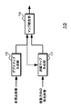
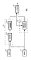
図1は、本技術の画像処理装置の機能構成を示すブロック図である。画像処理装置10は、デプスマップ生成部15と法線マップ生成部17およびマップ統合部19を有している。
<1. About Image Processing Device>
FIG. 1 is a block diagram illustrating a functional configuration of an image processing apparatus according to the present technology. The
デプスマップ生成部15は、多視点画像からデプスマップを生成する。多視点画像は、偏光特性の異なる画素を含む画素構成の第1の撮像部によって生成された第1の画像に基づく無偏光画像と、第1の撮像部と画素構成が異なる第2の撮像部によって生成された第2の画像に基づく無偏光画像を用いる。また、デプスマップ生成部15は、第1の画像に基づく偏光画像と、この偏光画像と偏光方向が等しい第2の画像に基づく偏光画像を用いてもよい。デプスマップ生成部15は、例えば右視点の無偏光画像と左視点の無偏光画像、または、偏光方向が等しい右視点の偏光画像と左視点の偏光画像を用いてマッチング処理を行い、画素毎にデプス値を格納したデプスマップを生成する。デプスマップ生成部15は、生成したデプスマップをマップ統合部19へ出力する。
The depth
法線マップ生成部17は、複数方向の偏光画像から法線マップを生成する。複数方向の偏光画像は、後述するように偏光方向が3方向以上である偏光画像である。法線マップ生成部17は、偏光特性の異なる画素を含む画素構成の第1の撮像部によって生成された偏光方向が3方向以上である画素で構成された第1の画像を用いる。また、法線マップ生成部17は、偏光特性の異なる画素を含む画素構成の第1の撮像部によって生成された偏光方向が複数の画素を含む第1の画像と、第1の撮像部と画素構成が異なる第2の撮像部によって生成された偏光方向が第1の画像とは異なる複数の画素を含む第2の画像を用いる。法線マップ生成部17は、偏光方向が3方向以上である偏光画像を用いて、画素毎に法線情報を格納した法線マップを生成する。なお、法線マップの法線情報は、法線情報を積分することで被写体の表面形状を取得できる情報であり、被写体の表面形状は相対値であって被写体までの距離に関する情報を含んでいない。法線マップ生成部17は、生成した法線マップをマップ統合部19へ出力する。また、法線マップ生成部17は、デプスマップ生成部15で生成されたデプスマップを用いることで、後述するように180度の不定性が解決されている法線マップを生成してもよい。
The normal
マップ統合部19は、デプスマップ生成部15で生成されたデプスマップと法線マップ生成部17で生成された法線マップの統合処理を行い、デプスマップ生成部15で生成されたデプスマップ以上の精度を有したデプスマップを生成する。マップ統合部19は、例えばデプスマップにおいてデプス値が取得できていない場合、法線マップを利用してデプス未取得領域に対応する被写体の表面形状を判別する。マップ統合部19は、判別した表面形状と取得済みのデプス値に基づきデプス未取得領域のデプス値を推定することで、デプスマップ生成部15で生成されたデプスマップ以上の精度を有したデプスマップを生成する。
The
<2.第1の実施の形態>
次に画像処理装置の第1の実施の形態について説明する。第1の実施の形態では、第1の撮像部が偏光特性の異なる画素を含む画素構成であり、第1の撮像部と画素構成が異なる第2の撮像部が偏光特性を有していない画素で構成されている場合について説明する。
<2. First Embodiment>
Next, a first embodiment of the image processing apparatus will be described. In the first embodiment, the first imaging unit has a pixel configuration including pixels having different polarization characteristics, and the second imaging unit having a pixel configuration different from that of the first imaging unit has no polarization characteristics. The case where it comprises is demonstrated.
<2−1.第1の実施の形態の構成と動作>
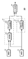
図2は、第1の実施の形態の構成を例示している。画像処理装置20は、撮像部21,22、デプスマップ生成部25、法線マップ生成部27、マップ統合部29を有している。撮像部21,22は、ステレオカメラに相当しており、画像処理装置20と別個に設けられてもよい。
<2-1. Configuration and Operation of First Embodiment>
FIG. 2 illustrates the configuration of the first embodiment. The
撮像部21は、偏光特性の異なる画素を含む画素構成である第1の撮像部に相当する。また、撮像部22は、偏光特性を有していない画素で構成されている第2の撮像部に相当する。
The
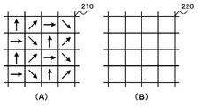
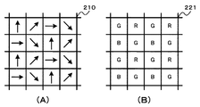
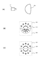
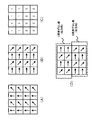
図3は、撮像部を構成するイメージセンサの画素構成を例示している。なお、図3はイメージセンサの一部を示している。また、図3の(A)は撮像部21を構成するイメージセンサ210の画素構成、図3の(B)は撮像部22を構成するイメージセンサ220の画素構成を示している。
FIG. 3 illustrates the pixel configuration of the image sensor that constitutes the imaging unit. FIG. 3 shows a part of the image sensor. 3A shows the pixel configuration of the
撮像部21のイメージセンサ210は、各画素に偏光フィルタが配置された構成とされている。例えば、図3の(A)に示すように、イメージセンサ210の偏光フィルタは、偏光方向(偏光方向を矢印で示す)が4方向とされており、撮像部21では、4方向の偏光画像が得られる。撮像部21は、生成した偏光画像をデプスマップ生成部25と法線マップ生成部27へ出力する。
The
撮像部22のイメージセンサ220は、偏光フィルタが配置されていない単一色(例えば白色)の画素で構成されている。例えば、図3の(B)に示すように、イメージセンサ220は、偏光フィルタが配置されておらず、撮像部22では無偏光画像が得られる。撮像部22は、生成した無偏光画像をデプスマップ生成部25へ出力する。
The
デプスマップ生成部25は、前処理部251、デプスマップ生成処理部255を有している。
The depth
前処理部251は、撮像部21から供給された偏光画像と撮像部22から供給された無偏光画像のそれぞれからマッチング処理に用いるマッチング画像を生成する。上述のように、撮像部21から供給された画像は、偏光フィルタを透過した偏光画像であるため、偏光フィルタが配置されていないイメージセンサを用いて撮像部22で生成された無偏光画像に比べて輝度が低下している。したがって、前処理部251は、輝度レベルの違いに対応したマッチング処理を行うことができるように、マッチング画像を生成する。前処理部251は、撮像部21から供給された偏光画像に対してフィルタ処理を行い無偏光画像を生成する。前処理部251は、例えば2画素×2画素の平均化フィルタ処理を行い、4方向の偏光方向の画素値の平均値を算出することで無偏光画像の画素値を生成できる。
The
次に、前処理部251は、撮像部21から供給された偏光画像のフィルタ処理を行うことにより得られた無偏光画像と、撮像部22から供給された無偏光画像に対して、エッジ抽出処理を行いそれぞれのエッジ抽出画像を生成する。前処理部251は、生成したそれぞれのエッジ抽出画像をマッチング画像としてデプスマップ生成処理部255へ出力する。このように、前処理部251は、エッジ抽出画像をマッチング画像として用いることから、輝度レベルの違いによる影響を受けることなくマッチング処理をデプスマップ生成処理部255で行うことができるようになる。
Next, the
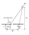
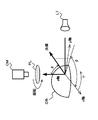
デプスマップ生成処理部255は、マッチング画像を用いてマッチング処理を行いデプスマップを生成する。マッチング手法は、領域ベースマッチングや特徴ベースマッチングテンプレートマッチングなど何れの手法を用いてもよい。デプスマップ生成処理部255は、マッチング処理を実行して、対応画素位置のずれ量に基づき各画素位置における被写体までの距離(以下「デプス値」という)を算出する。図4は、被写体までの距離の算出を説明するための図である。なお、図4は、撮像部21と撮像部22を同じ姿勢で左右に配置した場合を例示している。ここで、左側の撮像部を基準撮像部として右側の撮像部を参照撮像部とする。また、撮像部の基準位置の間隔(ベース長)を「LB」、撮像部の焦点距離を「f」とする。この場合、基準撮像部における被写体の位置XLに対して、参照撮像部における被写体の位置XRが「Ld」だけずれると、被写体までの距離「Zp」は、式(1)に基づいて算出できる。
The depth map

デプスマップ生成処理部255は、算出した距離(デプス値)を撮像画像の画素に対応付けてデプスマップを生成する。デプスマップ生成処理部255は、生成したデプスマップをマップ統合部29へ出力する。
The depth map
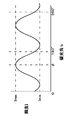
法線マップ生成部27は、法線マップ生成処理部275を有している。法線マップ生成処理部275は、撮像部21から供給された複数の偏光方向の偏光画像に基づき法線マップを生成する。図5は、偏光画像の生成動作を説明するための図である。図5に示すように、光源LTを用いて被写体OBの照明を行い、偏光板PLを介して被写体OBを撮像部CMで撮像する。この場合、撮像部CMで生成される偏光画像は、偏光板PLの回転に応じて被写体OBの輝度が変化することが知られている。ここで、偏光板PLを回転させたときの最も高い輝度をImax,最も低い輝度をIminとする。また、2次元座標におけるx軸とy軸を偏光板PLの平面方向としたとき、偏光板PLを回転させたときのx軸に対するxy平面上の角度を偏光角υとする。偏光板PLは、180度回転させると元の偏光状態に戻り180度の周期を有している。また、拡散反射のモデルの場合、最大輝度Imaxが観測されたときの偏光角υを方位角φとする。このような定義を行うと、偏光板PLを回転させたときに観測される輝度Iは式(2)のように表すことができる。なお、図6は、輝度と偏光角の関係を例示している。
The normal
式(2)では、偏光角υが偏光画像の生成時に明らかであり、最大輝度Imaxと最小輝度Iminおよび方位角φが変数となる。したがって、法線マップ生成処理部275は、変数が3つであることから、偏光方向が3方向以上の偏光画像の輝度を用いて式(2)に示す関数へのフィッティングを行い、輝度と偏光角の関係を示す関数に基づき最大輝度となる方位角φを判別する。
In Expression (2), the polarization angle υ is clear when the polarization image is generated, and the maximum brightness Imax, the minimum brightness Imin, and the azimuth angle φ are variables. Accordingly, since the normal map
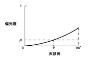
また、物体表面法線を極座標系で表現して、法線情報を方位角φと天頂角θとする。なお、天頂角θはz軸から法線に向かう角度、方位角φは、上述のようにx軸に対するy軸方向の角度とする。ここで、偏光板PLを回転して得られた最小輝度Iminと最大輝度Imaxを用いても式(3)の演算を行うことで偏光度ρを算出できる。 Further, the object surface normal is expressed in a polar coordinate system, and the normal information is defined as an azimuth angle φ and a zenith angle θ. The zenith angle θ is an angle from the z axis toward the normal, and the azimuth angle φ is an angle in the y axis direction with respect to the x axis as described above. Here, even when the minimum luminance Imin and the maximum luminance Imax obtained by rotating the polarizing plate PL are used, the degree of polarization ρ can be calculated by performing the calculation of Expression (3).
偏光度と天頂角と関係は、フレネルの式から例えば図7に示す特性を有することが知られており、図7に示す特性から偏光度ρに基づいて天頂角θを判別できる。なお、図7に示す特性は例示であって、被写体の屈折率に依存して特性は変化する。 The relationship between the degree of polarization and the zenith angle is known to have, for example, the characteristic shown in FIG. 7 from the Fresnel equation, and the zenith angle θ can be determined based on the degree of polarization ρ from the characteristic shown in FIG. Note that the characteristics shown in FIG. 7 are merely examples, and the characteristics change depending on the refractive index of the subject.
したがって、法線マップ生成処理部275は、偏光方向が3方向以上の偏光画像に基づき、偏光方向と偏光画像の輝度から輝度と偏光角の関係を求めて、最大輝度となる方位角φを判別する。また、法線マップ生成処理部275は、輝度と偏光角の関係から得た最大輝度と最小輝度を用いて偏光度ρを算出して、偏光度と天頂角の関係を示す特性曲線に基づき、算出した偏光度ρに対応する天頂角θを判別する。このように、法線マップ生成処理部275は、偏光方向が3方向以上の偏光画像に基づき、被写体の法線情報(方位角φと天頂角θ)を画素位置毎に求めて法線マップを生成する。法線マップ生成処理部275は、生成した法線マップをマップ統合部29へ出力する。
Therefore, the normal map
マップ統合部29は、デプスマップと法線マップの統合処理を行う。マップ統合部29は、法線マップで示された被写体表面形状とデプスマップで示されたデプス値に基づき、デプス値が得られている画素を起点として被写体表面形状を辿ることにより、デプス値が得られていない画素に対応するデプス値を推定する。また、マップ統合部29は、推定したデプス値をデプスマップ生成部25から供給されたデプスマップに含めることで、デプスマップ生成部25から供給されたデプスマップ以上の精度を有するデプスマップを生成する。
The
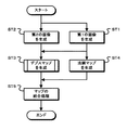
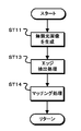
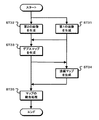
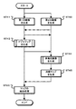
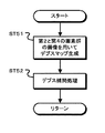
図8は、第1の実施の形態の処理動作を示すフローチャートである。ステップST1で撮像部21は、第1の画像を生成する。撮像部21は、複数の偏光方向の偏光画像を第1の画像として生成する。また、ステップST2で撮像部22は、第2の画像の生成を行う。撮像部22は、無偏光画像を第2の画像として生成する。
FIG. 8 is a flowchart showing the processing operation of the first embodiment. In step ST1, the
ステップST3でデプスマップ生成部25は、デプスマップを生成する。図9は、デプスマップ生成部の処理動作を示すフローチャートである。
In step ST3, the
ステップST11でデプスマップ生成部25は、無偏光画像を生成する。デプスマップ生成部25の前処理部251は、第1の画像すなわち複数の偏光方向の偏光画像に対して平均化フィルタ処理等を行い、無偏光画像を生成する。
In step ST11, the
ステップST13でデプスマップ生成部25は、エッジ抽出処理を行う。デプスマップ生成部25の前処理部251は、第2の画像である撮像部22で生成された無偏光画像と、ステップST11で生成した無偏光画像に対してエッジ抽出処理を行い、マッチング画像を生成する。デプスマップ生成部25は、このようにエッジ抽出処理を行うことで、第1の画像と第2の画像の輝度レベルの違いによる影響のないマッチング画像を生成できる。
In step ST13, the depth
ステップST14でデプスマップ生成部25は、マッチング処理を行う。デプスマップ生成部25のデプスマップ生成処理部255は、第1の画像から生成したマッチング画像と第2の画像から生成したマッチング画像を用いて、マッチング処理を行う。さらに、デプスマップ生成部25は、マッチング処理結果に基づき、画素毎にデプス値を示すデプスマップを生成する。
In step ST14, the depth
図8のステップST4で法線マップ生成部27は、法線マップを生成する。法線マップ生成部27は第1の画像を用いて、画素毎に方位角φと天頂角θを判別して法線マップを生成する。
In step ST4 of FIG. 8, the
ステップST5でマップ統合部29は、マップの統合処理を行う。マップ統合部29は、デプスマップで示されたデプス値と法線マップで示された被写体表面形状に基づき、デプス値が得られている画素を起点として被写体表面形状を辿ることにより、デプス値が得られていない画素に対応するデプス値を推定する。また、マップ統合部29は、推定したデプス値をデプスマップに含める。
In step ST5, the
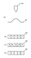
図10は、マップの統合処理を説明するための図である。なお、説明を簡単とするため、例えば1ラインについての統合処理について説明する。図10の(A)に示すように、撮像部21,22によって被写体OBの撮像を行い、デプスマップ生成部25で図10の(B)に示すデプスマップ、法線マップ生成部27で図10の(C)に示す法線マップが得られたとする。また、デプスマップでは、例えば左端の画素に対するデプス値が「2(メートル)」であり、「×」で示す他の画素ではデプス値が格納されていないとする。マップ統合部29は、法線マップに基づき、被写体OBの表面形状を推定する。ここで、左端から2番目の画素は、この画素の法線方向に基づき、左端の画素に対応する被写体面から撮像部21,22の方向に近づく傾斜面に相当していることが判別できる。したがって、マップ統合部29は、左端の画素を起点として被写体OBの表面形状を辿ることにより左端から2番目の画素のデプス値を推定して、例えば「1.5(メートル)」とする。また、マップ統合部29は、推定したデプス値をデプスマップに格納する。左端から3番目の画素は、この画素の法線方向に基づき撮像部21,22と対向する面に相当していることが判別できる。したがって、マップ統合部29は、左端の画素を起点として被写体OBの表面形状を辿ることにより左端から3番目の画素のデプス値を推定して、例えば「1(メートル)」とする。また、マップ統合部29は、推定したデプス値をデプスマップに格納する。左端から4番目の画素は、左端から3番目の画素に対応する被写体面から撮像部21,22と離れる方向の傾斜面に相当していることが判別できる。したがって、マップ統合部29は、左端の画素を起点として被写体OBの表面形状を辿ることにより左端から4番目の画素のデプス値を推定して、例えば「1.5(メートル)」とする。また、マップ統合部29は、推定したデプス値をデプスマップに格納する。同様に左端から5番目の画素のデプス値を推定して、例えば「2(メートル)」としてデプスマップに格納する。
FIG. 10 is a diagram for explaining the map integration processing. For the sake of simplicity, for example, an integration process for one line will be described. As shown in FIG. 10A, the
このように、マップ統合部29は、デプスマップと法線マップの統合処理を行い、デプスマップの持つデプス値を起点として法線マップに基づき表面形状を辿ることで、デプス値を推定する。したがって、マップ統合部29は、デプスマップ生成部25で生成された図10の(B)に示すデプスマップで一部のデプス値が欠損していても、欠損しているデプス値を補うことが可能となる。したがって、図10の(B)に示すデプスマップ以上の精度である図10の(D)に示すデプスマップを生成できる。
As described above, the
以上のように、第1の実施の形態によれば、マッチング処理ではデプス値の取得が困難な被写体領域についても、複数の偏光方向の偏光画像に基づいて生成された法線マップを用いてデプス値の推定が可能となる。したがって、デプスマップ生成部25で生成されたデプスマップ以上の精度を有した高精度のデプスマップ、すなわち被写体領域の画素毎にデプス値が格納されたデプスマップを生成できる。また、4つの画素を画像単位とした処理を行うことなく高精度のデプスマップを生成できることから、高精度のデプスマップを生成しつつ、画素数の減らない画像を取得できる。
As described above, according to the first embodiment, even with respect to a subject region where it is difficult to obtain a depth value by the matching process, the depth is obtained using the normal map generated based on the polarization images of a plurality of polarization directions. The value can be estimated. Therefore, it is possible to generate a high-precision depth map having a precision higher than that of the depth map generated by the depth
<2−2.第1の実施の形態の第1の変形例>
上述の実施の形態では、撮像部22において単一色の画素で構成されたイメージセンサを用いる構成を例示したが、複数色の画素で構成されたイメージセンサを用いる構成としてもよい。次に、第1の実施の形態の第1変形例として、赤色と青色と緑色の画素がベイヤー配列とされているイメージセンサを撮像部22で用いる場合について説明する。なお、画像処理装置の構成は、図2と同様な構成とする。
<2-2. First Modification of First Embodiment>
In the above-described embodiment, the configuration using the image sensor configured by pixels of a single color in the
図11は、第1の変形例における撮像部を構成するイメージセンサの画素構成を例示している。なお、図11はイメージセンサの一部を示している。また、図11の(A)は撮像部21を構成するイメージセンサ210の画素構成、図11の(B)は撮像部22を構成するイメージセンサ221の画素構成を示している。なお、「R」は赤色画素、「G」は緑色画素、「B」は青色画素であることを示している。
FIG. 11 illustrates the pixel configuration of the image sensor that constitutes the imaging unit in the first modification. FIG. 11 shows a part of the image sensor. 11A shows the pixel configuration of the
撮像部21のイメージセンサ210は、各画素に偏光フィルタが配置された構成とされている。例えば、図3の(A)に示すように、イメージセンサ210の偏光フィルタは、偏光方向(偏光方向を矢印で示す)が4方向とされており、撮像部21では、4方向の偏光画像が得られる。撮像部21は、生成した偏光画像をデプスマップ生成部25と法線マップ生成部27へ出力する。
The
撮像部22のイメージセンサ221は、例えば、図11の(B)に示すように、偏光フィルタが配置されておらず、三原色の画素(R,G,B)がベイヤー配列とされた構成とされており、撮像部22では無偏光画像が得られる。撮像部22は、生成した無偏光画像をデプスマップ生成部25へ出力する。
For example, as shown in FIG. 11B, the
デプスマップ生成部25は、前処理部251、デプスマップ生成処理部255を有している。
The depth
前処理部251は、撮像部21から供給された偏光画像と撮像部22から供給された無偏光画像のそれぞれからマッチング処理に用いるマッチング画像を生成する。上述のように、撮像部21から供給された画像は、偏光フィルタを透過した偏光画像であるため、偏光フィルタが配置されていないイメージセンサを用いて撮像部22で生成された無偏光画像に比べて輝度が低下している。したがって、前処理部251は、輝度レベルの違いに対応したマッチング処理を行うことができるように、マッチング画像を生成する。前処理部251は、撮像部21から供給された偏光画像に対してフィルタ処理を行い無偏光画像を生成する。前処理部251は、例えば2画素×2画素の平均化フィルタ処理を行い、4方向の偏光方向の画素値の平均値を算出することで無偏光画像の画素値を生成できる。
The
次に、前処理部251は、撮像部22で用いられているイメージセンサ221が三原色の画素をベイヤー配列とした構成であることから、デモザイク処理を行い輝度画像を生成する。前処理部251は、撮像部21から供給された偏光画像のフィルタ処理後の無偏光画像と、撮像部22から供給された無偏光画像に対してデモザイク処理を行うことにより得た輝度画像に対してエッジ抽出処理を行い、それぞれのエッジ抽出画像を生成する。前処理部251は、生成したそれぞれのエッジ抽出画像をマッチング画像としてデプスマップ生成処理部255へ出力する。このように、前処理部251は、エッジ抽出画像をマッチング画像として用いることから、輝度レベルの違いによる影響を受けることなくマッチング処理をデプスマップ生成処理部255で行うことができるようになる。
Next, since the
デプスマップ生成処理部255は、上述のようにマッチング画像を用いてマッチング処理を行いデプスマップを生成する。また、法線マップ生成部27は、上述のように撮像部21から供給された複数の偏光方向の偏光画像に基づき法線マップを生成する。
The depth map
マップ統合部29は、デプスマップと法線マップの統合処理を行う。マップ統合部29は、法線マップで示された被写体表面形状とデプスマップで示されたデプス値に基づき、デプス値が得られている画素を起点として被写体表面形状を辿ることにより、デプス値が得られていない画素に対応するデプス値を推定する。また、マップ統合部29は、推定したデプス値をデプスマップ生成部25から供給されたデプスマップに含めることで、デプスマップ生成部25から供給されたデプスマップ以上の精度を有するデプスマップを生成する。
The
図12は、第1の変形例におけるデプスマップ生成部の処理動作を示すフローチャートである。ステップST21でデプスマップ生成部25は、無偏光画像を生成する。デプスマップ生成部25の前処理部251は、第1の画像すなわち複数の偏光方向の偏光画像に対して平均化フィルタ処理等を行い、無偏光画像を生成する。
FIG. 12 is a flowchart illustrating the processing operation of the depth map generation unit in the first modification. In step ST21, the depth
ステップST22でデプスマップ生成部25は、輝度画像を生成する。デプスマップ生成部25の前処理部251は、第2の画像である撮像部22で生成された無偏光の三原色画像に対してデモザイク処理を行い輝度画像を生成する。
In step ST22, the depth
ステップST23でデプスマップ生成部25は、エッジ抽出処理を行う。デプスマップ生成部25の前処理部251は、ステップST21で生成した無偏光画像とステップST22で生成した輝度画像に対してエッジ抽出処理を行い、マッチング画像を生成する。デプスマップ生成部25は、このようにエッジ抽出処理を行うことで、第1の画像と第2の画像の輝度差の影響のないマッチング画像を生成できる。
In step ST23, the depth
ステップST24でデプスマップ生成部25は、マッチング処理を行う。デプスマップ生成部25のデプスマップ生成処理部255は、第1の画像から生成したマッチング画像と第2の画像から生成したマッチング画像を用いて、マッチング処理を行う。さらに、デプスマップ生成部25は、マッチング処理結果に基づき、デプス値を示すデプスマップを生成する。
In step ST24, the depth
このような処理を行えば、撮像部22において、三原色の画素(R,G,B)をベイヤー配列とした構成のイメージセンサを用いる場合でも、高精度のデプスマップを生成することができる。
By performing such processing, a high-precision depth map can be generated in the
<2−3.第1の実施の形態の第2の変形例>
上述の実施の形態における法線マップ生成部27は、複数の偏光方向の偏光画像を用いて法線マップを生成している。上述のように、偏光板PLは180度回転させると元の偏光状態に戻り、輝度変化は180度の周期を有しており、いわゆる180度の不定性を有することが知られている。そこで、第2の変形例では、デプスマップを用いて180度の不定性を除去する場合について説明する。
<2-3. Second Modification of First Embodiment>
The normal
図13は、第2の変形例の構成を例示している。画像処理装置20は、撮像部21,22、デプスマップ生成部25、法線マップ生成部27、マップ統合部29を有している。撮像部21,22は、ステレオカメラに相当しており、画像処理装置20と別個に設けられてもよい。
FIG. 13 illustrates the configuration of the second modification. The
撮像部21は、偏光特性の異なる画素を含む画素構成である第1の撮像部に相当する。また、撮像部22は、偏光特性を有していない画素で構成されている第2の撮像部に相当する。撮像部21は、例えば図3の(A)または図11の(A)に示す構成のイメージセンサを用いる。撮像部22は、例えば図3の(B)または図11の(B)に示す構成のイメージセンサを用いる。
The
デプスマップ生成部25は、前処理部251、デプスマップ生成処理部255を有している。前処理部251は、撮像部21から供給された偏光画像と撮像部22から供給された無偏光画像のそれぞれから上述のようにマッチング処理に用いるマッチング画像を生成する。デプスマップ生成処理部255は、マッチング画像を用いてマッチング処理を行いデプスマップを生成する。デプスマップ生成処理部255は、生成したデプスマップを法線マップ生成部27とマップ統合部29へ出力する。
The depth
法線マップ生成部27は、法線マップ生成処理部276を有している。法線マップ生成処理部276は、法線マップ生成処理部275と同様な処理を行い、撮像部21から供給された複数の偏光方向の偏光画像に基づき法線マップを生成する。また、法線マップ生成処理部276は、デプスマップに基づき被写体の勾配方向を判別して法線マップの生成を行い、180度の不定性を除去する。
The normal
図14は、法線マップ生成処理部の動作を説明するための図である。図14の(A)に示す被写体OBを撮像部21で撮像して法線マップを生成する場合、偏光方向の回転に応じた輝度変化は180度の周期を有している。したがって、例えば図14の(B)に示すように被写体OBの上半分の領域GAでは法線方向(矢印で示す)が正しい方向となり、下半分の領域GBでは法線方向が逆方向となるおそれがある。ここで、デプスマップに基づき被写体OBの勾配方向の判別を法線マップ生成処理部276で行うと、法線マップ生成処理部276は、被写体OBが撮像部21の方向に突出した形状であることを判別できる。また、法線マップ生成処理部276は、被写体OBが撮像部21の方向に突出した形状であることから、図14の(B)に示す下半分の領域GBの法線方向は逆方向であることを判別できる。したがって、法線マップ生成処理部276は、下半分の領域GBの法線方向を逆方向とすることで、図14の(C)に示すように、180度の不定性を除去した正しい法線マップを生成できる。
FIG. 14 is a diagram for explaining the operation of the normal map generation processing unit. When the subject OB shown in FIG. 14A is imaged by the
マップ統合部29は、デプスマップと法線マップの統合処理を行う。マップ統合部29は、法線マップで示された被写体表面形状とデプスマップで示されたデプス値に基づき、デプス値が得られている画素を起点として被写体表面形状を辿ることにより、デプス値が得られていない画素に対応するデプス値を推定する。また、マップ統合部29は、推定したデプス値をデプスマップ生成部25から供給されたデプスマップに含めることで、デプスマップ生成部25から供給されたデプスマップ以上の精度を有するデプスマップを生成する。
The
図15は、第2の変形例の処理動作を示すフローチャートである。ステップST31で撮像部21は、第1の画像を生成する。撮像部21は、複数の偏光方向の偏光画像を第1の画像として生成する。また、ステップST32で撮像部22は、第2の画像を生成する。撮像部22は、無偏光画像を第2の画像として生成する。
FIG. 15 is a flowchart showing the processing operation of the second modified example. In step ST31, the
ステップST33でデプスマップ生成部25は、デプスマップを生成する。デプスマップ生成部25は、無偏光画像の生成および無偏光画像に基づきマッチング画像の生成を行う。また、デプスマップ生成部25は、マッチング画像を用いてマッチング処理を行い、マッチング処理結果に基づき、デプス値を示すデプスマップを生成する。
In step ST33, the
ステップST34で法線マップ生成部27は、法線マップを生成する。法線マップ生成部27は第1の画像とデプスマップに基づき、180度の不定性を除去した法線マップを生成する。
In step ST34, the
ステップST35でマップ統合部29は、マップの統合処理を行う。マップ統合部29は、デプスマップで示されたデプス値と法線マップで示された被写体表面形状に基づき、デプス値が得られている画素を起点として被写体表面形状を辿ることにより、デプス値が得られていない画素に対応するデプス値を推定する。また、マップ統合部29は、推定したデプス値をデプスマップに含める。
In step ST35, the
このように、第2の変形例によれば、180度の不定性を除去して、正しい法線マップを生成することが可能となり、高精度のデプスマップを正しく生成できる。なお、第2の変形例では、法線マップ生成処理部276で正しい法線マップを生成してマップ統合部29へ出力したが、マップ統合部29で180度の不定性の除去を行うようにしてもよい。例えばマップ統合部29は、デプスマップに基づき被写体の勾配方向を判別して、判別結果に基づき上述の法線マップ生成処理部275で生成された法線マップの法線方向を正しい方向に修正してからマップの統合処理を行うようにしてもよい。
As described above, according to the second modification, it is possible to remove the indefiniteness of 180 degrees and generate a correct normal map, and it is possible to correctly generate a high-precision depth map. In the second modified example, the normal map
<3.第2の実施の形態について>
次に画像処理装置の第2の実施の形態について説明する。第2の実施の形態において、第1の画像は、偏光特性を有した画素からなる第1の画素群と、第1の画素群と異なる偏光方向の画素または偏光特性を持たない画素からなる第2の画素群とで構成された画素構成の第1の撮像部で生成された画像とする。第2の画像は、第1の画素群と対応する位置で偏光方向が第1の画像と異なる画素からなる第3の画素群と、第2の画素群と対応する位置で第2の画素群と等しい構成の画素からなる第4の画素群とで構成された画素構成の第2の撮像部で生成された画像とする。また、第2の実施の形態では、第1の画像における第2の画素群の画像と、第2の画像における第4画素群の画像とを用いることにより、偏光方向が等しい画像間または偏光特性を持たない画像間でマッチング処理を行いデプスマップを生成する。さらに、第2の画素群と第4の画素群が偏光特性を持たない画像である場合、第1の画素群と第3の画素群の偏光方向は合わせて3方向以上の偏光画像として、法線マップを生成する。
<3. Second Embodiment>
Next, a second embodiment of the image processing apparatus will be described. In the second embodiment, the first image includes a first pixel group including pixels having polarization characteristics, and pixels having a polarization direction different from that of the first pixel group or pixels having no polarization characteristics. It is assumed that the image is generated by the first imaging unit having a pixel configuration including two pixel groups. The second image includes a third pixel group including pixels whose polarization direction is different from that of the first image at a position corresponding to the first pixel group, and a second pixel group at a position corresponding to the second pixel group. And an image generated by the second imaging unit having a pixel configuration including a fourth pixel group including pixels having the same configuration. Further, in the second embodiment, by using the image of the second pixel group in the first image and the image of the fourth pixel group in the second image, the inter-image or polarization characteristics having the same polarization direction. A depth map is generated by performing a matching process between images having no. Further, when the second pixel group and the fourth pixel group are images having no polarization characteristics, the polarization directions of the first pixel group and the third pixel group are combined into three or more polarization images. Generate a line map.
<3−1.第2の実施の形態の構成と動作>
図16は、第2の実施の形態の構成を例示している。画像処理装置30は、撮像部31,32、デプスマップ生成部35、法線マップ生成部37、マップ統合部39を有している。撮像部31,32は、ステレオカメラに相当しており、画像処理装置30と別個に設けられてもよい。
<3-1. Configuration and Operation of Second Embodiment>
FIG. 16 illustrates the configuration of the second embodiment. The
撮像部31は、偏光特性を有した画素からなる第1の画素群と、第1の画素群と異なる偏光方向の画素または偏光特性を持たない画素からなる第2の画素群とで構成された画素構成である第1の撮像部に相当する。また、撮像部32は、第1の画素群と対応する位置で偏光方向が第1の画像とは異なる画素からなる第3の画素群と、第2の画素群と対応する位置で第2の画素群と等しい構成の画素からなる第4の画素群とで構成された画素構成である第2の撮像部に相当する。
The
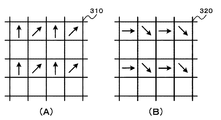
図17は、撮像部を構成するイメージセンサの画素構成を例示している。なお、図17はイメージセンサの一部を示している。また、図17の(A)は撮像部31を構成するイメージセンサ310の画素構成、図17の(B)は撮像部32を構成するイメージセンサ320の画素構成を示している。
FIG. 17 illustrates the pixel configuration of the image sensor that constitutes the imaging unit. FIG. 17 shows a part of the image sensor. 17A shows the pixel configuration of the
撮像部31のイメージセンサ310は、無偏光の画素と複数の偏光方向の偏光フィルタを設けた画素が混在した構成とされている。例えば、図17の(A)に示すように、イメージセンサ310には、1ラインおきに無偏光の画素ラインが設けられている。また、偏光フィルタを設けたラインでは、異なる2種類の偏光方向(偏光方向を矢印で示す)の画素が交互に設けられている。したがって、撮像部31では、第1の画素群である2方向の偏光方向の画素と第2の画素群である無偏光の画素からなる画像が得られる。撮像部31は、生成した画像をデプスマップ生成部35と法線マップ生成部37へ出力する。
The
撮像部32のイメージセンサ320は、無偏光の画素と複数の偏光方向の偏光フィルタを設けた画素が混在した構成とされている。例えば、図17の(B)に示すように、イメージセンサ320には、イメージセンサ310と同様に無偏光の画素ラインが設けられている。また、偏光フィルタを設けたラインでは、撮像部31のイメージセンサ310とは異なる2種類の偏光方向(偏光方向を矢印で示す)の画素が交互に設けられている。したがって、撮像部32では、撮像部31と異なる2方向の偏光方向である第3の画素群の画素と第4の画素群である無偏光の画素からなる画像が得られる。撮像部32は、生成した画像をデプスマップ生成部35と法線マップ生成部37へ出力する。すなわち、図17の場合、偏光方向が4方向の偏光画像が法線マップ生成部37へ出力されることになる。
The
デプスマップ生成部35は、前処理部351、デプスマップ生成処理部355を有している。
The depth
前処理部351は、撮像部31,32から供給された画像から無偏光部分の画像を抽出して、マッチング処理に用いるマッチング画像としてデプスマップ生成処理部355へ出力する。
The
デプスマップ生成処理部355は、マッチング画像を用いてマッチング処理を行いデプスマップを生成する。デプスマップ生成処理部355は、上述のデプスマップ生成処理部255と同様にマッチング処理を実行して、対応画素位置のずれ量に基づき各画素位置における被写体までの距離(デプス値)を算出する。また、デプスマップ生成処理部355は、無偏光部分の画素について算出したデプス値を用いてデプス補間処理を行い、偏光フィルタが設けられている画素のデプス値を算出する。デプスマップ生成処理部355は、デプス値を撮像画像の画素に対応付けてデプスマップを生成する。デプスマップ生成処理部355は、算出したデプス値を撮像画像の画素に対応付けてデプスマップを生成する。デプスマップ生成処理部355は、生成したデプスマップを法線マップ生成部37とマップ統合部39へ出力する。
The depth map
法線マップ生成部37は、画像位相調整部371と法線マップ生成処理部375を有している。
The normal
画像位相調整部371は、デプスマップ生成部35から出力されたデプスマップをディスパリティマップに変換する。画像位相調整部371は、デプスマップで示された画素毎のデプス値に基づき視差量を判別してディスパリティマップを生成する。なお、デプスマップ生成部35ではマッチング処理によって画素位置にずれ量を画素毎に算出していることから、画像位相調整部371は、デプスマップ生成部35から画素毎のずれ量を取得してディスパリティマップを生成してもよい。
The image
また、画像位相調整部371は、撮像部31と撮像部32から供給された画像のそれぞれに対して、偏光画像が得られていない無偏光画像のラインの画像補間処理を行い、偏光方向が異なる複数の方向の画素からなる偏光画像をそれぞれ生成する。図18は、撮像部から供給された画像と補間処理後の画像を示している。なお、図18の(A)は、撮像部31から供給された画像の偏光方向を示しており、図18の(B)は補間処理後の画像の偏光方向を示している。画像位相調整部371は、上側や下側に隣接する偏光画像の画素を用いて補間を行い、例えば上側に隣接する画素の画素値と下側に隣接する画素の画素値の平均値を無偏光画像の画素位置の画素値として、偏光方向が2方向の画素からなる偏光画像を生成する。画像位相調整部371は、撮像部32から供給された画像に対しても同様に画像補間処理を行い、撮像部31から供給された画像とは偏光方向が異なる2方向の画素からなる偏光画像を生成する。
In addition, the image
さらに、画像位相調整部371は、ディスパリティマップに基づき、撮像部31からの画像に対する補間処理後の偏光画像と撮像部32からの画像に対する補間処理後の偏光画像の位相を一致させる。図19は位相調整処理を説明するための図である。図19の(A)は撮像部31から供給された画像の補間処理後における偏光画像の一部を示している。図19の(B)は撮像部32から供給された画像の補間処理後における偏光画像の一部を示している。図19の(C)はディスパリティマップの一部を例示している。なお、ディスパリティマップのディスパリティ値(視差量)は、デプスマップのデプス値と一対一に対応しており、上述のように2つの撮像部の基準位置の間隔「LB」と撮像部の焦点距離「f」から容易に双方向で変換可能である。視差量は、被写体の同じ部分に対応する撮像部31から供給された画像上の画素と撮像部32から供給された画像上の画素の関係を示している。撮像部32から供給された画像上における例えば画素Pg2(図示せず)に対応する撮像部31から供給された画像上の画素Pg1(図示せず)は、ディスパリティマップの視差量を参照することで判別できる。ここで、視差量の値が「2(画素)」であるとすると、画素Pg2よりも2画素右側に位置する画素Pg1が被写体の同じ部分に対応する。したがって、画像位相調整部371は、ディスパリティマップを参照して、撮像部32から供給された補間処理後の画像の位相を調整して、撮像部31から供給された補間処理後の画像と画像の位相が一致している図19の(D)に示す位相一致画像を生成する。ここで、ディスパリティマップが図19の(C)に示す値である場合、上半分が「1(画素)」であり下半分が「2(画素)」である。したがって、画像位相調整部371は、撮像部32から供給された補間処理後の画像の上半分を「1(画素)」だけ右にずらす処理と、下半分を「2(画素)」だけ右にずらす処理を行い、位相を一致させた画像を生成する。
Furthermore, the image
画像位相調整部371は、以上のような処理を行い偏光方向が異なる2方向の偏光画像と、この画像と位相が一致しており偏光方向が異なる2方向の偏光画像を生成して法線マップ生成処理部375へ出力する。すなわち、画像位相調整部371は、被写体の視差の影響が除かれた多偏光画像を法線マップ生成処理部375へ出力する。
The image
法線マップ生成処理部375は、画像位相調整部371から供給された複数の偏光方向の偏光画像に基づき法線マップを生成して、マップ統合部39へ出力する。
The normal map
マップ統合部39は、デプスマップと法線マップの統合処理を行う。マップ統合部39は、法線マップで示された被写体表面形状とデプスマップで示されたデプス値に基づき、デプス値が得られている画素を起点として被写体表面形状を辿ることにより、デプス値が得られていない画素に対応するデプス値を推定する。また、マップ統合部39は、推定したデプス値をデプスマップ生成部35から供給されたデプスマップに含めることで、デプスマップ生成部35から供給されたデプスマップ以上の精度を有するデプスマップを生成する。
The
図20は、第2の実施の形態の処理動作を示すフローチャートである。ステップST41で撮像部31は、第1の画像を生成する。撮像部31は、偏光特性を有した画素からなる第1の画素群と、第1の画素群と異なる偏光方向の画素または偏光特性を持たない画素からなる第2の画素群からなる第1の画像を生成する。また、ステップST42で撮像部32は、第1の画素群と対応する位置で偏光方向が第1の画像と異なる画素からなる第3の画素群と、第2の画素群と対応する位置で第2の画素群と等しい構成の画素からなる第4の画素群からなる第2の画像を生成する。
FIG. 20 is a flowchart illustrating a processing operation according to the second embodiment. In step ST41, the
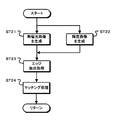
ステップST43でデプスマップ生成部35はデプスマップを生成する。図21はデプスマップの生成処理を示すフローチャートである。ステップST51でデプスマップ生成部35は、第2と第4の画素群を用いてデプスマップを生成する。デプスマップ生成部35は、第2と第4の画素群の画像を用いてマッチング処理を行い、画素毎に被写体までの距離(デプス値)を算出してデプスマップを生成する。
In step ST43, the
ステップST52でデプスマップ生成部35は、デプス補間処理を行う。デプスマップ生成部35は、第2(第4)の画素群の画素について算出したデプス値を用いた補間処理によって、第1(第3)の画素群の画素についてのデプス値を算出する。このように、デプスマップ生成部35は、デプス補間処理を行うことで第1(第3)の画素群および第2(第4)の画素群の画素毎にデプス値を示すデプスマップを生成する。
In step ST52, the depth
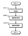
図20のステップST44で法線マップ生成部37は多偏光画像を生成する。図22は多偏光画像の生成処理を示すフローチャートである。ステップST61で法線マップ生成部37はディスパリティマップを生成する。法線マップ生成部37は、図20のステップST43で生成したデプスマップをディスパリティマップに変換する。なお、法線マップ生成部37は、ディスパリティマップ生成時に行われたマッチング処理によって得られた画素位置毎のずれ量を用いてもよい。
In step ST44 of FIG. 20, the normal
ステップST62で法線マップ生成部37は画像補間処理を行う。法線マップ生成部37は、撮像部31から供給された第1の画像と撮像部32から供給された第2の画像のそれぞれに対して、偏光画像が得られていない無偏光画像の画素位置に対して画像補間処理を行い偏光画像を生成する。
In step ST62, the normal
ステップST63で法線マップ生成部37は画像位相調整を行う。法線マップ生成部37は、ディスパリティマップに基づき画像の移動を行い、第1の画像に対する補間処理後の偏光画像と第2の画像に対する補間処理後の偏光画像における画像の位相を一致させて、視差の影響を除いた多偏光画像を生成する。
In step ST63, the normal
図20のステップST45で法線マップ生成部37は法線マップを生成する。法線マップ生成部37は、ステップST44で生成された多偏光画像に基づき法線マップを生成する。
In step ST45 of FIG. 20, the normal
ステップST46でマップ統合部39は、マップの統合処理を行う。マップ統合部39は、デプスマップで示されたデプス値と法線マップで示された被写体表面形状に基づき、デプス値が得られている画素を起点として被写体表面形状を辿ることにより、デプス値が得られていない画素に対応するデプス値を推定する。また、マップ統合部39は、推定したデプス値をデプスマップに含める。
In step ST46, the
以上のように、第2の実施の形態によれば、例えば第1の撮像部と第2の撮像部のそれぞれで偏光画像を生成する場合でも、デプスマップ生成部35でデプスマップを生成することが可能となる。また、法線マップ生成部37では、画像の位相合わせを行い視差の影響を除いた多偏光画像に基づき法線マップを生成することが可能となる。したがって、生成されたデプスマップと法線マップと統合することで、デプスマップ生成部35で生成されたデプスマップ以上の精度を有した高精度のデプスマップ、すなわち被写体領域の画素毎にデプス値が格納されたデプスマップを生成できる。また、高精度のデプスマップを生成しつつ、画素数の減らない画像を取得できる
As described above, according to the second embodiment, for example, even when a polarization image is generated by each of the first imaging unit and the second imaging unit, the depth
さらに、撮像部31のイメージセンサおよび撮像部32のイメージセンサの画素には、最大で偏光方向が2方向の平均化フィルタのみが行われるため、平均化フィルタの影響を抑えて高精度のデプスマップを生成できる。
Further, since only the averaging filter having the maximum polarization direction of two directions is applied to the pixels of the image sensor of the
<3−2.第2の実施の形態の第1の変形例>
上述の実施の形態では、撮像部31,32において単一色の画素で構成されたイメージセンサを用いる構成を例示したが、複数色の画素で構成されたイメージセンサを用いる構成としてもよい。次に、第2の実施の形態の第2変形例として、赤色と青色と緑色の画素がベイヤー配列とされているイメージセンサを撮像部31,32で用いる場合について説明する。なお、画像処理装置の構成は、図16と同様な構成する。
<3-2. First Modification of Second Embodiment>
In the above-described embodiment, the configuration using the image sensor including single color pixels in the
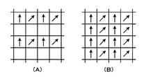
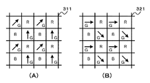
図23は、第1の変形例における撮像部を構成するイメージセンサの画素構成を例示している。なお、図23はイメージセンサの一部を示している。また、図23の(A)は撮像部31を構成するイメージセンサ311の画素構成、図23の(B)は撮像部32を構成するイメージセンサ321の画素構成を示している。なお、「R」は赤色画素、「G」は緑色画素、「B」は青色画素であることを示している。
FIG. 23 illustrates a pixel configuration of an image sensor that constitutes the imaging unit in the first modification. FIG. 23 shows a part of the image sensor. 23A shows the pixel configuration of the
撮像部31のイメージセンサ311は、赤色と青色と緑色の画素がベイヤー配列とされており、所定色の画素例えば緑画素に偏光フィルタが配置された構成とされている。図23の(A)に示すように、イメージセンサ311の偏光フィルタは、異なる2種類の偏光方向(偏光方向を矢印で示す)とされている。撮像部31は、第1の画素群である2方向の偏光方向の画素(緑色)および第2の画素群の無偏光の画素(赤色と青色)の画像からなる第1の画像を生成して、デプスマップ生成部35と法線マップ生成部37へ出力する。
The
撮像部32のイメージセンサ321は、赤色と青色と緑色の画素がベイヤー配列とされており、緑画素に偏光フィルタが配置された構成とされている。例えば、図23の(B)に示すように、イメージセンサ321の偏光フィルタは、イメージセンサ311と異なる2種類の偏光方向(偏光方向を矢印で示す)とされている。撮像部32は、撮像部31と異なる2方向の偏光方向の第3の画素群である画素(緑色)および第4の画素群の無偏光の画素(赤色と青色)の画像からなる第2の画像を生成して、デプスマップ生成部35と法線マップ生成部37へ出力する。
The
デプスマップ生成部35は、前処理部351、デプスマップ生成処理部355を有している。前処理部351は、撮像部31と撮像部32から供給された画像の無偏光画像を用いてマッチング処理に用いるマッチング画像を生成する。例えば赤色画素または青色画素のみを用いて画像補間処理を行い、赤色または青色のマッチング画像を生成する。デプスマップ生成処理部355は、マッチング画像を用いてマッチング処理を行いデプスマップを生成する。
The depth
法線マップ生成部37は、画像位相調整部371と法線マップ生成処理部375を有している。
The normal
画像位相調整部371は、デプスマップ生成部35から出力されたデプスマップをディスパリティマップに変換する。画像位相調整部371は、デプスマップで示された画素毎のデプス値に基づき視差量を判別してディスパリティマップを生成する。なお、デプスマップ生成部35ではマッチング処理によって画素毎にずれ量を算出していることから、画像位相調整部371は、デプスマップ生成部35から画素毎のずれ量を取得してディスパリティマップを生成してもよい。
The image
画像位相調整部371は、撮像部31と撮像部32から供給された画像のそれぞれに対して、偏光画像を用いて無偏光画像の画像補間処理を行い、偏光方向が異なる複数の方向の画素からなる偏光画像をそれぞれ生成する。さらに画像位相調整部371は、ディスパリティマップに基づき、撮像部31からの画像に対する補間処理後の偏光画像と撮像部31からの画像に対する補間処理後の偏光画像の位相を一致させて、被写体の視差の影響が除かれた多偏光画像を生成する。画像位相調整部371は、生成した多偏光画像を法線マップ生成処理部375へ出力する。
The image
法線マップ生成処理部375は、画像位相調整部371から供給された複数の偏光方向の偏光画像に基づき法線マップを生成して、マップ統合部39へ出力する。
The normal map
マップ統合部39は、デプスマップと法線マップの統合処理を行う。マップ統合部39は、法線マップで示された被写体表面形状とデプスマップで示されたデプス値に基づき、デプス値が得られている画素を起点として被写体表面形状を辿ることにより、デプス値が得られていない画素に対応するデプス値を推定する。また、マップ統合部39は、推定したデプス値をデプスマップ生成部35から供給されたデプスマップに含めることで、デプスマップ生成部35から供給されたデプスマップ以上の精度を有するデプスマップを生成する。
The
このように、第1の変形例によれば、複数色の画素で構成されたイメージセンサを用いる場合でも、デプスマップ生成部35でデプスマップを生成することが可能となる。また、法線マップ生成部37では、画像の位相合わせを行い視差の影響を除いた多偏光画像に基づき法線マップを生成することが可能となる。したがって、生成されたデプスマップと法線マップと統合することで、デプスマップ生成部35で生成されたデプスマップ以上の精度を有したデプスマップを生成できる。
Thus, according to the first modification, the depth map can be generated by the depth
<3−3.第2の実施の形態の第2の変形例>
次に、第2の実施の形態の第2の変形例として、撮像部31から供給された第1の画像の第1の画素群と撮像部32から供給された第2の画像の第3の画素群との偏光方向が異なり、第1の画像の第2の画素群と第2の画像の第4の画素群の偏光方向が、第1および第2の画素群とは異なる偏光方向で互いに等しい場合について説明する。なお、画像処理装置の構成は、図16と同様な構成する。
<3-3. Second Modification of Second Embodiment>
Next, as a second modification example of the second embodiment, the first pixel group of the first image supplied from the
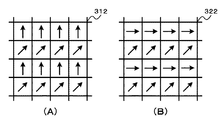
図24は、第2の変形例における撮像部を構成するイメージセンサの画素構成を例示している。なお、図24はイメージセンサの一部を示している。また、図24の(A)は撮像部31を構成するイメージセンサ312の画素構成、図24の(B)は撮像部32を構成するイメージセンサ322の画素構成を示している。
FIG. 24 illustrates the pixel configuration of the image sensor that constitutes the imaging unit in the second modification. FIG. 24 shows a part of the image sensor. 24A shows the pixel configuration of the
撮像部31のイメージセンサ312は、各画素に偏光フィルタが配置された構成とされている。例えば、図24の(A)に示すように、イメージセンサ312の偏光フィルタは、異なる2種類の偏光方向(偏光方向を矢印で示す)とされている。また、同じラインの画素は偏光方向が等しく構成されている。撮像部31は、1つの偏光方向の第1の画素群のラインと他の偏光方向の第2の画素群のラインからなる第1の画像を生成して、デプスマップ生成部35と法線マップ生成部37へ出力する。
The
撮像部32のイメージセンサ322は、各画素に偏光フィルタが配置された構成とされている。例えば、図24の(B)に示すように、イメージセンサ322の偏光フィルタは、イメージセンサ312と等しい偏光方向(偏光方向を矢印で示す)と異なる偏光方向とされている。また、同じラインの画素は偏光方向が等しく構成されている。撮像部32は、撮像部31と異なる偏光方向の第3の画素群のラインと撮像部31の第2の画素群と等しい偏光方向の第4の画素群のラインからなる第2の画像を生成して、デプスマップ生成部35と法線マップ生成部37へ出力する。したがって、図24の場合には、偏光方向が3方向の偏光画像が法線マップ生成部37へ供給される。なお、図24では、イメージセンサ312,322において、等しい偏光方向が右上方向である場合を例示している。
The
デプスマップ生成部35は、前処理部351、デプスマップ生成処理部355を有している。前処理部351は、撮像部31と撮像部32から供給された画像を用いてマッチング処理に用いるマッチング画像を生成する。前処理部351は、撮像部31と撮像部32で偏光方向が等しい画素の画像のみを用いて画像補間処理を行いマッチング画像を生成する。デプスマップ生成処理部355は、マッチング画像を用いてマッチング処理を行いデプスマップを生成する。
The depth
法線マップ生成部37は、画像位相調整部371と法線マップ生成処理部375を有している。
The normal
画像位相調整部371は、撮像部31と撮像部32の位置の違いによって視差を生じることから、視差の影響が除かれた偏光画像を生成する。画像位相調整部371は、デプスマップ生成部35から出力されたデプスマップをディスパリティマップに変換する。画像位相調整部371は、デプスマップで示された画素毎のデプス値に基づき視差量を判別してディスパリティマップを生成する。なお、デプスマップ生成部35ではマッチング処理によって画素毎にずれ量を算出していることから、画像位相調整部371は、デプスマップ生成部35から画素毎のずれ量を取得してディスパリティマップを生成してもよい。
The image
また、画像位相調整部371は、ディスパリティマップに基づき、撮像部31からの偏光画像と撮像部32からの偏光画像の位相を一致させて、被写体の視差の影響が除かれた多偏光画像を法線マップ生成処理部375へ出力する。
Further, the image
法線マップ生成処理部375は、画像位相調整部371から供給された複数の偏光方向の偏光画像に基づき法線マップを生成して、マップ統合部39へ出力する。
The normal map
マップ統合部39は、デプスマップと法線マップの統合処理を行う。マップ統合部39は、法線マップで示された被写体表面形状とデプスマップで示されたデプス値に基づき、デプス値が得られている画素を起点として被写体表面形状を辿ることにより、デプス値が得られていない画素に対応するデプス値を推定する。また、マップ統合部39は、推定したデプス値をデプスマップ生成部35から供給されたデプスマップに含めることで、デプスマップ生成部35から供給されたデプスマップ以上の精度を有するデプスマップを生成する。
The
このように、第2の変形例によれば、撮像部31から供給された画像が複数の偏光方向の画像であり、撮像部32から供給された画像が撮像部31と等しい偏光方向と異なる偏光方向の画像である場合でも、デプスマップを生成することが可能となる。また、法線マップ生成部37では、画像の位相合わせを行い視差の影響を除いた多偏光画像に基づき法線マップを生成することが可能となる。したがって、生成されたデプスマップと法線マップと統合することで、デプスマップ生成部35で生成されたデプスマップ以上の精度を有したデプスマップを生成できる。
As described above, according to the second modification, the image supplied from the
さらに、第2の実施の形態においても第1の実施の形態と同様に、デプスマップを用いて180度の不定性を除去して法線マップの生成してもよい。180度の不定性を除去することで、第2の実施の形態においても、精度よくデプスマップを生成できるようになる。 Further, in the second embodiment, as in the first embodiment, a normal map may be generated by removing 180 degrees of indefiniteness using a depth map. By removing the indefiniteness of 180 degrees, the depth map can be generated with high accuracy also in the second embodiment.
<4.第3の実施の形態>
上述の第1および第2の実施の形態では、画像処理装置に複数の撮像部が設けられている構成について例示したが、撮像部は分離可能な構成であってもよい。
<4. Third Embodiment>
In the first and second embodiments described above, the configuration in which the image processing apparatus is provided with a plurality of imaging units is illustrated, but the imaging unit may be configured to be separable.
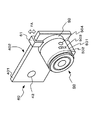
図25は、第3の実施の形態の外観を例示している。なお、図25では、画像処理装置として例えばスマートフォンを用いている。 FIG. 25 illustrates the appearance of the third embodiment. In FIG. 25, for example, a smartphone is used as the image processing apparatus.
画像処理装置40は、略長方形のケース状に形成され外筐401の内部に、図示せずも信号処理部、通信部、制御部等を有している。また、外筐401の一方の面(表面)に表示パネル402が設けられている。表示パネル402はタッチパネルを用いて構成されており表示パネル402の所定の各位置を操作することにより各種機能が実行される。外筐401の他方の面(裏面)に撮像部42が設けられている。
The
撮像装置50は、円筒状に形成された外筒部501の内部に、図示せずも撮像光学系、撮像部、信号処理部、通信部、制御部等を有している。外筒部501の前端部には円環状のコントロールリング502が設けられている。撮像装置50は、コントロールリング502の回転に応じてフォーカス位置やズーム位置を変更する。また、外筒部501の側面にはズームボタン503とシャッターボタン504が設けられている。
The
撮像装置50には、画像処理装置40と撮像装置50を一体的に取り付けるための取付機構部60が設けられている。取付機構部60には、取付部材61が設けられており、矢印FA方向に移動可能に構成されている。ユーザは、取付部材61を矢印FA方向に移動させて画像処理装置40の外筐401に係止させて、撮像装置50を画像処理装置40の例えば裏面側に一体的に固定する。このように撮像装置50を画像処理装置40に一体的に固定することで、撮像部42と撮像装置50でステレオ画像を生成することが可能となる。また、ユーザは、画像処理装置40の外筐401に係止されている取付部材61を、係止方向に対して逆方向に移動させて、画像処理装置40と撮像装置50を分離する。
The
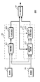
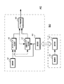
図26は、第3の実施の形態の構成を例示している。画像処理装置40は、撮像部42と通信部43、デプスマップ生成部45、法線マップ生成部47、マップ統合部49を有している。また、撮像装置50は、撮像部51と通信部53を有している。
FIG. 26 illustrates the configuration of the third embodiment. The
画像処理装置40の撮像部42は、例えば第1の実施の形態の撮像部22や第2の実施の形態の撮像部32に相当する。撮像部42が撮像部22に相当する場合、撮像部42は生成した画像をデプスマップ生成部45へ出力する。また、撮像部42が撮像部32に相当する場合、撮像部42は生成した画像をデプスマップ生成部45と法線マップ生成部47へ出力する。
The
撮像装置50の撮像部51は、例えば第1の実施の形態の撮像部21や第2の実施の形態の撮像部31に相当する。撮像部51は生成した画像を通信部53へ出力する。通信部53は、NFC(Near Field Communication)通信やWi−Fi通信等の無線通信を行うことができるように構成されている。通信部53は、撮像部51で生成された画像を画像処理装置40へ送信する。
The
画像処理装置40の通信部43は、撮像装置50の通信部53と同様に構成されている。通信部43は、撮像装置50の通信部53から送信された無線信号を受信して、撮像装置50から送信された画像をデプスマップ生成部45と法線マップ生成部47へ出力する。
The
デプスマップ生成部45は、第1の実施の形態のデプスマップ生成部25や第2の実施の形態のデプスマップ生成部35と同様な処理を行い、デプスマップを生成してマップ統合部49へ出力する。
The depth
法線マップ生成部47は、第1の実施の形態の法線マップ生成部27や第2の実施の形態の法線マップ生成部37と同様な処理を行い、法線マップを生成してマップ統合部49へ出力する。
The normal
マップ統合部49は、第1の実施の形態のマップ統合部29や第2の実施の形態のマップ統合部39と同様な処理を行い、デプスマップと法線マップに基づき、デプスマップ生成部45で生成されたデプスマップ以上の精度を有するデプスマップを生成して出力する。
The
このような第3の実施の形態によれば、撮像部が分離可能な構成でも、高精度のデプスマップを生成しつつ、画素数の減らない画像を取得できる。したがって、例えばスマートフォン等の情報処理装置に偏光方向が3方向以上の偏光画像を生成する撮像装置を取り付けて、高精度のデプスマップを生成可能とすることで、既存の情報処理装置の機能を拡張できる。 According to the third embodiment, an image in which the number of pixels is not reduced can be acquired while generating a high-precision depth map even in a configuration in which the imaging unit can be separated. Therefore, for example, by attaching an imaging device that generates polarized images with three or more polarization directions to an information processing device such as a smartphone, it is possible to generate a high-precision depth map, thereby extending the functions of existing information processing devices. it can.
また、上述の実施の形態の一部構成を用いて撮像装置を構成してもよい。例えば、撮像装置は、偏光特性の異なる画素を含む画素構成の第1の撮像部と、第1の撮像部と画素構成が異なる第2の撮像部、および第1の撮像部によって生成された第1の画像と第2の撮像部によって生成された第2の画像を用いて画像処理を行う画像処理部を備える構成とする。また、撮像装置は、例えば第1の撮像部の画素構成を、偏光特性を有した画素からなる第1の画素群と、第1の画素群と異なる偏光方向の画素または偏光特性を持たない画素からなる第2の画素群とで構成された画素構成とする。また、第2の撮像部の画素構成は、第1の画素群と対応する位置で偏光方向が第1の画像とは異なる画素からなる第3の画素群と、第2の画素群と対応する位置で第2の画素群と等しい構成の画素からなる第4の画素群とで構成された画素構成とする。このように撮像装置を構成すれば、高精度のデプスマップを生成しつつ画素数の減らない画像を取得するために用いる処理対象の画像を容易に生成できる。なお、撮像装置の画像処理部で上述のようにデプスマップや法線マップの生成およびデプスマップと法線マップの統合処理を行うようにすれば、撮像装置から高精度のデプスマップおよび画素数の減らない画像を出力することが可能となる。また、この撮像装置と同様に画像処理装置を構成してもよい。 Moreover, you may comprise an imaging device using the partial structure of the above-mentioned embodiment. For example, the imaging device includes a first imaging unit having a pixel configuration including pixels having different polarization characteristics, a second imaging unit having a pixel configuration different from that of the first imaging unit, and a first imaging unit generated by the first imaging unit. An image processing unit that performs image processing using one image and the second image generated by the second imaging unit is provided. In addition, the imaging apparatus includes, for example, a pixel configuration of the first imaging unit, a first pixel group including pixels having polarization characteristics, and a pixel having a polarization direction different from that of the first pixel group or a pixel having no polarization characteristics. A pixel configuration including a second pixel group consisting of In addition, the pixel configuration of the second imaging unit corresponds to the third pixel group, which includes pixels having a polarization direction different from that of the first image at a position corresponding to the first pixel group, and the second pixel group. The pixel configuration includes a fourth pixel group including pixels having the same configuration as that of the second pixel group at the position. By configuring the imaging apparatus in this way, it is possible to easily generate an image to be processed that is used to acquire an image in which the number of pixels is not reduced while generating a highly accurate depth map. If the image processing unit of the imaging device generates the depth map or the normal map and integrates the depth map and the normal map as described above, the imaging device can obtain a high-precision depth map and the number of pixels. It is possible to output an image that does not decrease. Further, an image processing apparatus may be configured in the same manner as this imaging apparatus.
また、明細書中において説明した一連の処理はハードウェア、またはソフトウェア、あるいは両者の複合構成によって実行することが可能である。ソフトウェアによる処理を実行する場合は、処理シーケンスを記録したプログラムを、専用のハードウェアに組み込まれたコンピュータ内のメモリにインストールして実行させる。または、各種処理が実行可能な汎用コンピュータにプログラムをインストールして実行させることが可能である。 The series of processing described in the specification can be executed by hardware, software, or a combined configuration of both. When processing by software is executed, a program in which a processing sequence is recorded is installed and executed in a memory in a computer incorporated in dedicated hardware. Alternatively, the program can be installed and executed on a general-purpose computer capable of executing various processes.
例えば、プログラムは記録媒体としてのハードディスクやSSD(Solid State Drive)、ROM(Read Only Memory)に予め記録しておくことができる。あるいは、プログラムはフレキシブルディスク、CD−ROM(Compact Disc Read Only Memory),MO(Magneto optical)ディスク,DVD(Digital Versatile Disc)、BD(Blu-Ray Disc(登録商標))、磁気ディスク、半導体メモリカード等のリムーバブル記録媒体に、一時的または永続的に格納(記録)しておくことができる。このようなリムーバブル記録媒体は、いわゆるパッケージソフトウェアとして提供することができる。また、プログラムは、リムーバブル記録媒体からコンピュータにインストールする他、ダウンロードサイトからLAN(Local Area Network)やインターネット等のネットワークを介して、コンピュータに無線または有線で転送してもよい。コンピュータでは、そのようにして転送されてくるプログラムを受信し、内蔵するハードディスク等の記録媒体にインストールすることができる。 For example, the program can be recorded in advance on a hard disk, an SSD (Solid State Drive), or a ROM (Read Only Memory) as a recording medium. Alternatively, the program is a flexible disk, CD-ROM (Compact Disc Read Only Memory), MO (Magneto optical) disk, DVD (Digital Versatile Disc), BD (Blu-Ray Disc (registered trademark)), magnetic disk, semiconductor memory card. It can be stored (recorded) in a removable recording medium such as temporarily or permanently. Such a removable recording medium can be provided as so-called package software. In addition to installing the program from the removable recording medium to the computer, the program may be transferred from the download site to the computer wirelessly or by wire via a network such as a LAN (Local Area Network) or the Internet. The computer can receive the program transferred in this way and install it on a recording medium such as a built-in hard disk.
また、本技術は、上述した技術の実施の形態に限定して解釈されるべきではない。この技術の実施の形態は、例示という形態で本技術を開示しており、本技術の要旨を逸脱しない範囲で当業者が実施の形態の修正や代用をなし得ることは自明である。すなわち、本技術の要旨を判断するためには、特許請求の範囲を参酌すべきである。 Further, the present technology should not be construed as being limited to the embodiments of the technology described above. The embodiments of this technology disclose the present technology in the form of examples, and it is obvious that those skilled in the art can make modifications and substitutions of the embodiments without departing from the gist of the present technology. In other words, in order to determine the gist of the present technology, the claims should be taken into consideration.
なお、本技術の画像処理装置は以下のような構成も取ることができる。
(1) 偏光方向が異なる画素を含む画素構成の第1の撮像部によって生成された第1の画像と、前記第1の撮像部と画素構成が異なる第2の撮像部によって生成された第2の画像とを用いたマッチング処理によって、デプスマップを生成するデプスマップ生成部と、
前記デプスマップ生成部により生成された第1の画像または第2の画像の少なくとも何れかの偏光画像の偏光状態に基づいて法線マップを生成する法線マップ生成部と、
前記デプスマップ生成部で生成されたデプスマップと前記法線マップ生成部で生成された法線マップの統合処理を行うマップ統合部とを有する画像処理装置。
(2) 前記法線マップ生成部は、前記偏光方向が3方向以上の偏光画像の輝度に基づいて前記法線マップを生成する(1)に記載の画像処理装置。
(3) 前記マップ統合部は、前記デプスマップで示されたデプス値と前記法線マップに基づいて判別した形状から、前記デプスマップで示されていないデプス値を推定する(1)または(2)の何れかに記載の画像処理装置。
(4) 前記第1の画像は、前記偏光方向が3方向以上の画素を含む前記第1の撮像部によって生成された画像であり、
前記第2の画像は、偏光特性を持たない画素で構成された前記第2の撮像部によって生成された画像であり、
前記法線マップ生成部は、前記第1の画像に基づき法線マップを生成する(1)乃至(3)の何れかに記載の画像処理装置。
(5) 前記デプスマップ生成部は、第1の画像から無偏光画像を生成して、前記無偏光画像と前記第2の画像を用いて前記マッチング処理を行う(4)に記載の画像処理装置。
(6) 前記デプスマップ生成部は、前記無偏光画像と前記第2の画像のそれぞれに対してエッジ抽出を行い、前記無偏光画像のエッジ抽出画像と前記第2の画像のエッジ抽出画像を用いて前記マッチング処理を行う(5)に記載の画像処理装置。
(7) 前記第2の画像は、全画素に同色のカラーフィルタが設けられた前記第2の撮像部、または前記カラーフィルタが設けられていない前記第2の撮像部によって生成された画像であり、
前記デプスマップ生成部は、第2の画像から生成した無偏光画像を用いて前記マッチング処理を行う(4)乃至(6)の何れかに記載の画像処理装置。
(8) 前記第1の画像は、偏光特性を有した画素からなる第1の画素群と、前記第1の画素群と異なる偏光方向の画素または偏光特性を持たない画素からなる第2の画素群とで構成された画素構成の前記第1の撮像部で生成された画像であり、
前記第2の画像は、前記第1の画素群と対応する位置で偏光方向が前記第1の画像とは異なる偏光方向の画素からなる第3の画素群と、前記第2の画素群と対応する位置で前記第2の画素群と等しい偏光方向の画素または偏光特性を持たない画素からなる第4の画素群とで構成された画素構成の前記第2の撮像部で生成された画像である(3)に記載の画像処理装置。
(9) 前記デプスマップ生成部は、前記第1の画像における前記第2の画素群の画像と、前記第2の画像における前記第4画素群の画像とを用いることにより、偏光方向が等しい画像間または偏光特性を持たない画像間で前記マッチング処理を行う(8)に記載の画像処理装置。
(10) 前記第1の画像と前記第2の画像の視差量に基づき、前記第1の画像における前記第1の画素群の画像と、前記第2の画像における前記第3画素群の画像の位相を一致させて、偏光方向が複数方向の偏光画像を生成する画像位相調整部をさらに有し、
前記法線マップ生成部は、前記画像位相調整部で生成された偏光画像の偏光状態に基づいて法線マップを生成する(8)または(9)の何れかに記載の画像処理装置。
(11) 前記第2の画素群と前記第4の画素群が偏光特性を持たない画像である場合、前記第1の画素群と前記第3の画素群の偏光方向は合わせて3方向以上の画像とする(8)乃至(10)の何れかに記載の画像処理装置。
(12) 前記画像位相調整部は、前記第2の画素群と前記第4の画素群が偏光特性を持たない画像である場合、前記第1の画素群の画像を用いた補間処理によって前記第2の画素群の画像を生成し、前記第3の画素群の画像を用いた補間処理によって前記第4の画素群の画像を生成して、補間後の画像を用いて前記偏光画像を生成する(8)乃至(11)の何れかに記載の画像処理装置。
(13) 前記第1と第3の画素群は所定色の画素であり、前記第2と第4の画素群は、他の色の画素である(8)乃至(12)の何れかに記載の画像処理装置。
(14) 前記法線マップ生成部は、前記デプスマップ生成部で生成されたデプスマップを用いて前記法線マップの生成を行う(3)乃至(13)の何れかに記載の画像処理装置。
(15) 前記第1の画像を生成する第1の撮像部と前記第2の画像を生成する第2の撮像部をさらに有する(1)乃至(14)の何れかに記載の画像処理装置。
(16) 前記第1の撮像部と前記第2の撮像部の何れか一方が設けられた外部装置と通信を行い、前記外部装置に設けられた撮像部で生成された画像を取得する通信部と、
前記外部装置に設けられた撮像部とは異なる他方の撮像部をさらに有する(1)乃至(15)の何れかに記載の画像処理装置。
Note that the image processing apparatus of the present technology may also have the following configuration.
(1) A first image generated by a first imaging unit having a pixel configuration including pixels having different polarization directions, and a second image generated by a second imaging unit having a pixel configuration different from that of the first imaging unit. A depth map generating unit that generates a depth map by a matching process using the image of
A normal map generation unit that generates a normal map based on the polarization state of the polarization image of at least one of the first image and the second image generated by the depth map generation unit;
An image processing apparatus comprising: a map integration unit that performs integration processing of the depth map generated by the depth map generation unit and the normal map generated by the normal map generation unit.
(2) The image processing device according to (1), wherein the normal map generation unit generates the normal map based on a luminance of a polarization image having three or more polarization directions.
(3) The map integration unit estimates a depth value that is not indicated by the depth map from a shape determined based on the depth value indicated by the depth map and the normal map (1) or (2 ).
(4) The first image is an image generated by the first imaging unit that includes pixels having three or more polarization directions,
The second image is an image generated by the second imaging unit configured by pixels having no polarization characteristics,
The image processing apparatus according to any one of (1) to (3), wherein the normal map generation unit generates a normal map based on the first image.
(5) The image processing apparatus according to (4), wherein the depth map generation unit generates a non-polarized image from the first image, and performs the matching process using the non-polarized image and the second image. .
(6) The depth map generation unit performs edge extraction on each of the non-polarized image and the second image, and uses the edge extracted image of the non-polarized image and the edge extracted image of the second image. The image processing apparatus according to (5), wherein the matching process is performed.
(7) The second image is an image generated by the second imaging unit in which a color filter of the same color is provided in all pixels, or the second imaging unit in which the color filter is not provided. ,
The image processing apparatus according to any one of (4) to (6), wherein the depth map generation unit performs the matching process using a non-polarized image generated from the second image.
(8) The first image includes a first pixel group including pixels having polarization characteristics, and a second pixel including pixels having a polarization direction different from that of the first pixel group or pixels having no polarization characteristics. An image generated by the first imaging unit having a pixel configuration including a group,
The second image corresponds to a third pixel group composed of pixels having a polarization direction different from that of the first image at a position corresponding to the first pixel group, and the second pixel group. Is an image generated by the second imaging unit having a pixel configuration including a pixel having a polarization direction equal to that of the second pixel group at a position or a fourth pixel group including pixels having no polarization characteristics. The image processing apparatus according to (3).
(9) The depth map generation unit uses the image of the second pixel group in the first image and the image of the fourth pixel group in the second image, so that images having the same polarization direction are used. (8) The image processing apparatus according to (8), wherein the matching process is performed between images or images having no polarization characteristics.
(10) Based on the amount of parallax between the first image and the second image, the image of the first pixel group in the first image and the image of the third pixel group in the second image It further has an image phase adjustment unit that matches the phases and generates a polarization image having a plurality of polarization directions,
The image processing apparatus according to any one of (8) and (9), wherein the normal map generation unit generates a normal map based on a polarization state of the polarization image generated by the image phase adjustment unit.
(11) When the second pixel group and the fourth pixel group are images having no polarization characteristics, the polarization directions of the first pixel group and the third pixel group are three or more directions in total. The image processing apparatus according to any one of (8) to (10), which is an image.
(12) When the second pixel group and the fourth pixel group are images that do not have polarization characteristics, the image phase adjusting unit performs the first process by an interpolation process using an image of the first pixel group. An image of the second pixel group is generated, an image of the fourth pixel group is generated by an interpolation process using the image of the third pixel group, and the polarization image is generated using the image after interpolation. (8) The image processing device according to any one of (11).
(13) The first and third pixel groups are pixels of a predetermined color, and the second and fourth pixel groups are pixels of another color, according to any one of (8) to (12). Image processing apparatus.
(14) The image processing device according to any one of (3) to (13), wherein the normal map generation unit generates the normal map using the depth map generated by the depth map generation unit.
(15) The image processing device according to any one of (1) to (14), further including a first imaging unit that generates the first image and a second imaging unit that generates the second image.
(16) A communication unit that communicates with an external device provided with either one of the first imaging unit and the second imaging unit and acquires an image generated by the imaging unit provided in the external device When,
The image processing apparatus according to any one of (1) to (15), further including another imaging unit different from the imaging unit provided in the external device.
この技術の画像処理装置と画像処理方法および撮像装置では、偏光方向が異なる画素を含む画素構成の第1の撮像部によって生成された第1の画像と、前記第1の撮像部と画素構成が異なる第2の撮像部によって生成された第2の画像とを用いたマッチング処理によって、デプスマップが生成される。また、第1または第2の画像の少なくとも何れかの偏光画像の偏光状態に基づいて法線マップが生成される。さらに、生成されたデプスマップと法線マップの統合処理が行われる。このため、高精度のデプスマップを生成しつつ、画素数の減らない画像を取得できるようになる。したがって、被写体の3次元形状を取得する機器等に適している。 In the image processing apparatus, the image processing method, and the imaging apparatus according to this technique, a first image generated by a first imaging unit having a pixel configuration including pixels having different polarization directions, and the first imaging unit and the pixel configuration A depth map is generated by matching processing using a second image generated by a different second imaging unit. A normal map is generated based on the polarization state of at least one of the polarization images of the first or second image. Furthermore, the integrated processing of the generated depth map and normal map is performed. Therefore, it is possible to acquire an image in which the number of pixels is not reduced while generating a highly accurate depth map. Therefore, it is suitable for a device that acquires a three-dimensional shape of a subject.
10,20,30,40・・・画像処理装置、15,25,35,45・・・デプスマップ生成部、17,27,37,47・・・法線マップ生成部、19,29,39,49・・・マップ統合部、21,22,31,32,42,51・・・撮像部、43,53・・・通信部、50・・・撮像装置、53・・・通信部、60・・・取付機構部、61・・・取付部材、210,220,221,310,311,312,320,321,322・・・イメージセンサ、251,351・・・前処理部、255,355・・・デプスマップ生成処理部、275,276,375・・・法線マップ生成処理部、371・・・画像位相調整部、375・・・法線マップ生成処理部、401・・・外筐、402・・・表示パネル、501・・・外筒部、502・・・コントロールリング、503・・・ズームボタン、504・・・シャッターボタン
10, 20, 30, 40 ... image processing device, 15, 25, 35, 45 ... depth map generation unit, 17, 27, 37, 47 ... normal map generation unit, 19, 29, 39 , 49 ... Map integration unit, 21, 22, 31, 32, 42, 51 ... Imaging unit, 43, 53 ... Communication unit, 50 ... Imaging device, 53 ... Communication unit, 60 ... Attachment mechanism part, 61 ... Attachment member, 210,220,221,310,311,312,320,321,322 ... Image sensor, 251,351 ... Pre-processing part, 255,355 ... Depth map generation processing unit, 275, 276, 375 ... Normal map generation processing unit, 371 ... Image phase adjustment unit, 375 ... Normal map generation processing unit, 401 ...
Claims (20)
前記デプスマップ生成部により生成された第1の画像または第2の画像の少なくとも何れかの偏光画像の偏光状態に基づいて法線マップを生成する法線マップ生成部と、
前記デプスマップ生成部で生成されたデプスマップと前記法線マップ生成部で生成された法線マップの統合処理を行うマップ統合部と
を有する画像処理装置。 A first image generated by a first imaging unit having a pixel configuration including pixels having different polarization directions, and a second image generated by a second imaging unit having a pixel configuration different from that of the first imaging unit. A depth map generating unit that generates a depth map by matching processing using
A normal map generation unit that generates a normal map based on the polarization state of the polarization image of at least one of the first image and the second image generated by the depth map generation unit;
An image processing apparatus comprising: a map integration unit that performs integration processing of the depth map generated by the depth map generation unit and the normal map generated by the normal map generation unit.
請求項1記載の画像処理装置。 The image processing apparatus according to claim 1, wherein the normal map generation unit generates the normal map based on a luminance of a polarized image having three or more polarization directions.
請求項2記載の画像処理装置。 The image processing apparatus according to claim 2, wherein the map integration unit estimates a depth value not indicated by the depth map from a shape determined based on the depth value indicated by the depth map and the normal map.
前記第2の画像は、偏光特性を持たない画素で構成された前記第2の撮像部によって生成された画像であり、
前記法線マップ生成部は、前記第1の画像に基づき法線マップを生成する
請求項3記載の画像処理装置。 The first image is an image generated by the first imaging unit including pixels in which the polarization direction is three or more directions,
The second image is an image generated by the second imaging unit configured by pixels having no polarization characteristics,
The image processing apparatus according to claim 3, wherein the normal map generation unit generates a normal map based on the first image.
請求項4に記載の画像処理装置。 The image processing apparatus according to claim 4, wherein the depth map generation unit generates a non-polarized image from the first image, and performs the matching process using the non-polarized image and the second image.
請求項5に記載の画像処理装置。 The depth map generation unit performs edge extraction on each of the non-polarized image and the second image, and uses the edge extracted image of the non-polarized image and the edge extracted image of the second image to perform the matching The image processing apparatus according to claim 5, which performs processing.
前記デプスマップ生成部は、第2の画像から生成した無偏光画像を用いて前記マッチング処理を行う
請求項4に記載の画像処理装置。 The second image is an image generated by the second imaging unit in which a color filter of the same color is provided in all pixels, or the second imaging unit in which the color filter is not provided,
The image processing apparatus according to claim 4, wherein the depth map generation unit performs the matching process using a non-polarized image generated from the second image.
前記第2の画像は、前記第1の画素群と対応する位置で偏光方向が前記第1の画像とは異なる画素からなる第3の画素群と、前記第2の画素群と対応する位置で前記第2の画素群と等しい構成の画素からなる第4の画素群とで構成された画素構成の前記第2の撮像部で生成された画像である
請求項3記載の画像処理装置。 The first image includes a first pixel group composed of pixels having polarization characteristics, and a second pixel group composed of pixels having a polarization direction different from that of the first pixel group or pixels having no polarization characteristics. An image generated by the first imaging unit having a configured pixel configuration;
The second image has a position corresponding to the first pixel group and a position corresponding to the second pixel group, and a third pixel group including pixels having a polarization direction different from that of the first image. The image processing apparatus according to claim 3, wherein the image processing apparatus is an image generated by the second imaging unit having a pixel configuration including a fourth pixel group including pixels having the same configuration as the second pixel group.
請求項8に記載の画像処理装置。 The depth map generation unit uses an image of the second pixel group in the first image and an image of the fourth pixel group in the second image, so that the polarization directions are equal or polarized. The image processing apparatus according to claim 8, wherein the matching process is performed between images having no characteristics.
前記法線マップ生成部は、前記画像位相調整部で生成された偏光画像の偏光状態に基づいて法線マップを生成する
請求項8に記載の画像処理装置。 Based on the amount of parallax between the first image and the second image, the phase of the image of the first pixel group in the first image and the image of the third pixel group in the second image are matched. And having an image phase adjustment unit that generates a polarization image having a plurality of polarization directions,
The image processing apparatus according to claim 8, wherein the normal map generation unit generates a normal map based on a polarization state of the polarization image generated by the image phase adjustment unit.
請求項8記載の画像処理装置。 When the second pixel group and the fourth pixel group are images that do not have polarization characteristics, the polarization directions of the first pixel group and the third pixel group are three or more directions in total. The image processing apparatus according to claim 8.
請求項8に記載の画像処理装置。 When the second pixel group and the fourth pixel group are images having no polarization characteristics, the image phase adjustment unit is configured to perform the second pixel by an interpolation process using an image of the first pixel group. 9. An image of a group is generated, an image of the fourth pixel group is generated by an interpolation process using the image of the third pixel group, and the polarization image is generated using the image after interpolation. An image processing apparatus according to 1.
請求項8記載の画像処理装置。 The image processing apparatus according to claim 8, wherein the first and third pixel groups are pixels of a predetermined color, and the second and fourth pixel groups are pixels of other colors.
請求項3に記載の画像処理装置。 The image processing apparatus according to claim 3, wherein the normal map generation unit generates the normal map using the depth map generated by the depth map generation unit.
請求項1記載の画像処理装置。 The image processing apparatus according to claim 1, further comprising: a first imaging unit that generates the first image and a second imaging unit that generates the second image.
前記外部装置に設けられた撮像部とは異なる他方の撮像部をさらに有する
請求項1記載の画像処理装置。 A communication unit that communicates with an external device provided with either one of the first imaging unit and the second imaging unit, and acquires an image generated by the imaging unit provided in the external device;
The image processing apparatus according to claim 1, further comprising another imaging unit different from the imaging unit provided in the external device.
法線マップ生成部で、前記生成された第1または第2の画像の少なくとも何れかの偏光画像の偏光状態に基づいて法線マップを生成する工程と、
マップ統合部で、前記デプスマップと前記法線マップの統合処理を行う工程と
を含む画像処理方法。 The depth map generation unit generates a first image generated by a first imaging unit having a pixel configuration including pixels having different polarization directions, and a second imaging unit having a pixel configuration different from that of the first imaging unit. Performing a matching process using the second image and generating a depth map;
A step of generating a normal map based on a polarization state of at least one of the generated polarization images of the generated first or second image in the normal map generation unit;
An image processing method including a step of performing integration processing of the depth map and the normal map in a map integration unit.
前記第1の撮像部と画素構成が異なる第2の撮像部と、
前記第1の撮像部により生成された第1の画像と前記第2の撮像部より生成された第2の画像とを用いて、画像処理を行う画像処理部と
を備える撮像装置。 A first imaging unit having a pixel configuration including pixels having different polarization directions;
A second imaging unit having a pixel configuration different from that of the first imaging unit;
An imaging apparatus comprising: an image processing unit that performs image processing using a first image generated by the first imaging unit and a second image generated by the second imaging unit.
前記第2の撮像部は、前記第1の画素群と対応する位置で偏光方向が前記第1の画像とは異なる画素からなる第3の画素群と、前記第2の画素群と対応する位置で前記第2の画素群と等しい構成の画素からなる第4の画素群とで構成された画素構成である
請求項18に記載の撮像装置。 The first imaging unit includes a first pixel group including pixels having polarization characteristics, and a second pixel group including pixels having a polarization direction different from that of the first pixel group or pixels having no polarization characteristics. A pixel configuration composed of
The second imaging unit includes a third pixel group including pixels having a polarization direction different from that of the first image at a position corresponding to the first pixel group, and a position corresponding to the second pixel group. The imaging device according to claim 18, wherein the imaging device has a pixel configuration including a fourth pixel group including pixels having the same configuration as the second pixel group.
前記第1の撮像部と画素構成が異なる第2の撮像部と、
前記受信部により受信成された第1の画像と前記第2の撮像部より生成された第2の画像とを用いて、画像処理を行う画像処理部と
を備える画像処理装置。 The first image is obtained from an image processing apparatus including a first imaging unit having a pixel configuration including pixels having different polarization directions and a transmission unit that transmits the first image generated by the first imaging unit. A receiving unit for receiving;
A second imaging unit having a pixel configuration different from that of the first imaging unit;
An image processing apparatus comprising: an image processing unit that performs image processing using a first image received by the receiving unit and a second image generated by the second imaging unit.
Priority Applications (5)
| Application Number | Priority Date | Filing Date | Title |
|---|---|---|---|
| JP2013259075A JP2015114307A (en) | 2013-12-16 | 2013-12-16 | Image processing apparatus, image processing method, and imaging apparatus |
| US15/032,549 US10574972B2 (en) | 2013-12-16 | 2014-11-17 | Image processing device, image processing method, and imaging device |
| CN201480067375.8A CN105814401B (en) | 2013-12-16 | 2014-11-17 | Image processing apparatus, image processing method and imaging device |
| EP14871842.2A EP3086085B1 (en) | 2013-12-16 | 2014-11-17 | Image processing device, image processing method, and imaging device |
| PCT/JP2014/080323 WO2015093205A1 (en) | 2013-12-16 | 2014-11-17 | Image processing device, image processing method, and imaging device |
Applications Claiming Priority (1)
| Application Number | Priority Date | Filing Date | Title |
|---|---|---|---|
| JP2013259075A JP2015114307A (en) | 2013-12-16 | 2013-12-16 | Image processing apparatus, image processing method, and imaging apparatus |
Publications (1)
| Publication Number | Publication Date |
|---|---|
| JP2015114307A true JP2015114307A (en) | 2015-06-22 |
Family
ID=53402560
Family Applications (1)
| Application Number | Title | Priority Date | Filing Date |
|---|---|---|---|
| JP2013259075A Pending JP2015114307A (en) | 2013-12-16 | 2013-12-16 | Image processing apparatus, image processing method, and imaging apparatus |
Country Status (5)
| Country | Link |
|---|---|
| US (1) | US10574972B2 (en) |
| EP (1) | EP3086085B1 (en) |
| JP (1) | JP2015114307A (en) |
| CN (1) | CN105814401B (en) |
| WO (1) | WO2015093205A1 (en) |
Cited By (13)
| Publication number | Priority date | Publication date | Assignee | Title |
|---|---|---|---|---|
| WO2017002716A1 (en) * | 2015-07-01 | 2017-01-05 | 株式会社ソニー・インタラクティブエンタテインメント | Image processing device, image processing system, multi-view camera, and image processing method |
| WO2018034210A1 (en) | 2016-08-18 | 2018-02-22 | Sony Corporation | Imaging device for obtaining polarized and non-polarized images |
| WO2018061508A1 (en) * | 2016-09-28 | 2018-04-05 | ソニー株式会社 | Image capturing element, image processing device, image processing method, and program |
| WO2018207661A1 (en) * | 2017-05-11 | 2018-11-15 | ソニー株式会社 | Optical sensor and electronic apparatus |
| WO2018216341A1 (en) * | 2017-05-22 | 2018-11-29 | ソニー株式会社 | Information processing device, information processing method, and program |
| WO2019021591A1 (en) * | 2017-07-28 | 2019-01-31 | ソニー株式会社 | Image processing device, image processing method, program, and image processing system |
| WO2019026714A1 (en) | 2017-08-04 | 2019-02-07 | ソニー株式会社 | Information processing device, information processing method, program and mobile unit |
| WO2019116708A1 (en) * | 2017-12-12 | 2019-06-20 | ソニー株式会社 | Image processing device, image processing method and program, and image processing system |
| WO2019220722A1 (en) * | 2018-05-18 | 2019-11-21 | ソニー株式会社 | Solid-state imaging device, device and method for information processing, and calibration method |
| JP2020507136A (en) * | 2018-01-12 | 2020-03-05 | 北京小米移動軟件有限公司Beijing Xiaomi Mobile Software Co.,Ltd. | VR object synthesizing method, apparatus, program, and recording medium |
| WO2020054152A1 (en) | 2018-09-12 | 2020-03-19 | ソニー株式会社 | Image processing device, image processing method, and program |
| WO2020105201A1 (en) * | 2018-11-22 | 2020-05-28 | ソニーセミコンダクタソリューションズ株式会社 | Image capturing device and electronic apparatus |
| JPWO2019021569A1 (en) * | 2017-07-26 | 2020-06-11 | ソニー株式会社 | Information processing apparatus, information processing method, and program |
Families Citing this family (18)
| Publication number | Priority date | Publication date | Assignee | Title |
|---|---|---|---|---|
| JP2015115041A (en) * | 2013-12-16 | 2015-06-22 | ソニー株式会社 | Image processor, and image processing method |
| US10260866B2 (en) * | 2015-03-06 | 2019-04-16 | Massachusetts Institute Of Technology | Methods and apparatus for enhancing depth maps with polarization cues |
| JP6620050B2 (en) * | 2016-03-28 | 2019-12-11 | 株式会社ショーワ | Image processing apparatus, in-vehicle image processing apparatus, program, and recording medium |
| JP2018029280A (en) * | 2016-08-18 | 2018-02-22 | ソニー株式会社 | Imaging device and imaging method |
| JP6615723B2 (en) * | 2016-09-07 | 2019-12-04 | 株式会社ソニー・インタラクティブエンタテインメント | Information processing apparatus and object recognition method |
| US20180124378A1 (en) * | 2016-11-03 | 2018-05-03 | Qualcomm Incorporated | Enhanced depth map images for mobile devices |
| JP6684475B2 (en) * | 2017-03-13 | 2020-04-22 | オムロン株式会社 | Image processing apparatus, image processing method and program |
| US11029253B2 (en) * | 2017-03-30 | 2021-06-08 | Applied Materials Israel Ltd. | Computerized method for configuring an inspection system, computer program product and an inspection system |
| US10803546B2 (en) * | 2017-11-03 | 2020-10-13 | Baidu Usa Llc | Systems and methods for unsupervised learning of geometry from images using depth-normal consistency |
| CN108876835A (en) * | 2018-03-28 | 2018-11-23 | 北京旷视科技有限公司 | Depth information detection method, device and system and storage medium |
| US11676245B2 (en) * | 2018-05-24 | 2023-06-13 | Sony Corporation | Information processing apparatus and method for processing information |
| CN109470166B (en) * | 2018-11-09 | 2020-12-08 | 业成科技(成都)有限公司 | Structured light depth sensor and sensing method |
| US10721458B1 (en) * | 2018-12-14 | 2020-07-21 | Ambarella International Lp | Stereoscopic distance measurements from a reflecting surface |
| KR102714205B1 (en) | 2019-02-28 | 2024-10-10 | 삼성전자주식회사 | Image sensor |
| CN110686652B (en) * | 2019-09-16 | 2021-07-06 | 武汉科技大学 | A depth measurement method based on the combination of deep learning and structured light |
| US11127147B2 (en) * | 2019-12-10 | 2021-09-21 | GM Global Technology Operations LLC | Three-dimensional point cloud generation using a polarimetric camera in a drive assistance system equipped vehicle |
| CN113532381A (en) * | 2021-08-05 | 2021-10-22 | 湖南旺轩科技有限公司 | Wind tower settlement measuring device and measuring method |
| EP4411658A4 (en) * | 2021-09-27 | 2025-05-07 | Sony Semiconductor Solutions Corporation | Information processing device and information processing method |
Family Cites Families (12)
| Publication number | Priority date | Publication date | Assignee | Title |
|---|---|---|---|---|
| JP3267625B2 (en) * | 1995-10-23 | 2002-03-18 | サイトメトリクス インコーポレイテッド | Method and apparatus for reflection image analysis |
| JPH11211433A (en) * | 1998-01-30 | 1999-08-06 | Toppan Printing Co Ltd | Method and system for measuring surface shape of molded article |
| JP2009147814A (en) | 2007-12-17 | 2009-07-02 | Fujitsu Ten Ltd | Acoustic system and acoustic control method |
| JP4435867B2 (en) * | 2008-06-02 | 2010-03-24 | パナソニック株式会社 | Image processing apparatus, method, computer program, and viewpoint conversion image generation apparatus for generating normal line information |
| US8167041B2 (en) * | 2008-07-03 | 2012-05-01 | Masdar Institute Of Science And Technology | Apparatus and method for energy-efficient and environmentally-friendly recovery of bitumen |
| JP4636149B2 (en) * | 2008-09-09 | 2011-02-23 | ソニー株式会社 | Image data analysis apparatus, image data analysis method, and program |
| KR101497503B1 (en) * | 2008-09-25 | 2015-03-04 | 삼성전자주식회사 | Method and apparatus for generating depth map for conversion two dimensional image to three dimensional image |
| JP5541653B2 (en) | 2009-04-23 | 2014-07-09 | キヤノン株式会社 | Imaging apparatus and control method thereof |
| JP5440927B2 (en) * | 2009-10-19 | 2014-03-12 | 株式会社リコー | Distance camera device |
| JP5899684B2 (en) * | 2011-07-11 | 2016-04-06 | ソニー株式会社 | Image processing apparatus, image processing method, and program |
| JP5982751B2 (en) * | 2011-08-04 | 2016-08-31 | ソニー株式会社 | Image processing apparatus, image processing method, and program |
| CN102446382A (en) * | 2011-11-08 | 2012-05-09 | 北京新岸线网络技术有限公司 | Self-service terminal of three-dimensional operation |
-
2013
- 2013-12-16 JP JP2013259075A patent/JP2015114307A/en active Pending
-
2014
- 2014-11-17 CN CN201480067375.8A patent/CN105814401B/en not_active Expired - Fee Related
- 2014-11-17 EP EP14871842.2A patent/EP3086085B1/en active Active
- 2014-11-17 WO PCT/JP2014/080323 patent/WO2015093205A1/en not_active Ceased
- 2014-11-17 US US15/032,549 patent/US10574972B2/en active Active
Cited By (31)
| Publication number | Priority date | Publication date | Assignee | Title |
|---|---|---|---|---|
| WO2017002716A1 (en) * | 2015-07-01 | 2017-01-05 | 株式会社ソニー・インタラクティブエンタテインメント | Image processing device, image processing system, multi-view camera, and image processing method |
| JP2017016431A (en) * | 2015-07-01 | 2017-01-19 | 株式会社ソニー・インタラクティブエンタテインメント | Image processing device, image processing system, multi-viewpoint camera, and processing method |
| WO2018034210A1 (en) | 2016-08-18 | 2018-02-22 | Sony Corporation | Imaging device for obtaining polarized and non-polarized images |
| US10877288B2 (en) | 2016-08-18 | 2020-12-29 | Sony Corporation | Imaging device and imaging method |
| WO2018061508A1 (en) * | 2016-09-28 | 2018-04-05 | ソニー株式会社 | Image capturing element, image processing device, image processing method, and program |
| WO2018207661A1 (en) * | 2017-05-11 | 2018-11-15 | ソニー株式会社 | Optical sensor and electronic apparatus |
| JP7044107B2 (en) | 2017-05-11 | 2022-03-30 | ソニーグループ株式会社 | Optical sensors and electronic devices |
| JPWO2018207661A1 (en) * | 2017-05-11 | 2020-06-18 | ソニー株式会社 | Optical sensor and electronic device |
| WO2018216341A1 (en) * | 2017-05-22 | 2018-11-29 | ソニー株式会社 | Information processing device, information processing method, and program |
| US11488354B2 (en) | 2017-05-22 | 2022-11-01 | Sony Corporation | Information processing apparatus and information processing method |
| JPWO2019021569A1 (en) * | 2017-07-26 | 2020-06-11 | ソニー株式会社 | Information processing apparatus, information processing method, and program |
| JP7103357B2 (en) | 2017-07-26 | 2022-07-20 | ソニーグループ株式会社 | Information processing equipment, information processing methods, and programs |
| WO2019021591A1 (en) * | 2017-07-28 | 2019-01-31 | ソニー株式会社 | Image processing device, image processing method, program, and image processing system |
| WO2019026714A1 (en) | 2017-08-04 | 2019-02-07 | ソニー株式会社 | Information processing device, information processing method, program and mobile unit |
| US11373418B2 (en) | 2017-08-04 | 2022-06-28 | Sony Corporation | Information processing apparatus, information processing method, program, and mobile object |
| WO2019116708A1 (en) * | 2017-12-12 | 2019-06-20 | ソニー株式会社 | Image processing device, image processing method and program, and image processing system |
| CN111465818A (en) * | 2017-12-12 | 2020-07-28 | 索尼公司 | Image processing apparatus, image processing method, program and information processing system |
| JPWO2019116708A1 (en) * | 2017-12-12 | 2020-12-17 | ソニー株式会社 | Image processing equipment and image processing methods and programs and information processing systems |
| JP7136123B2 (en) | 2017-12-12 | 2022-09-13 | ソニーグループ株式会社 | Image processing apparatus, image processing method, program, and information processing system |
| JP2020507136A (en) * | 2018-01-12 | 2020-03-05 | 北京小米移動軟件有限公司Beijing Xiaomi Mobile Software Co.,Ltd. | VR object synthesizing method, apparatus, program, and recording medium |
| US11636653B2 (en) | 2018-01-12 | 2023-04-25 | Beijing Xiaomi Mobile Software Co., Ltd. | Method and apparatus for synthesizing virtual and real objects |
| JPWO2019220722A1 (en) * | 2018-05-18 | 2021-07-01 | ソニーグループ株式会社 | Solid-state image sensor and information processing device, information processing method and calibration method |
| WO2019220722A1 (en) * | 2018-05-18 | 2019-11-21 | ソニー株式会社 | Solid-state imaging device, device and method for information processing, and calibration method |
| JPWO2020054152A1 (en) * | 2018-09-12 | 2021-08-30 | ソニーグループ株式会社 | Image processing equipment and image processing methods and programs |
| WO2020054152A1 (en) | 2018-09-12 | 2020-03-19 | ソニー株式会社 | Image processing device, image processing method, and program |
| JP7276346B2 (en) | 2018-09-12 | 2023-05-18 | ソニーグループ株式会社 | Image processing device, image processing method and program |
| US11930160B2 (en) | 2018-09-12 | 2024-03-12 | Sony Corporation | Image processing apparatus, image processing method, and program |
| JP2020088565A (en) * | 2018-11-22 | 2020-06-04 | ソニーセミコンダクタソリューションズ株式会社 | Imaging apparatus and electronic apparatus |
| US11457201B2 (en) | 2018-11-22 | 2022-09-27 | Sony Semiconductor Solutions Corporation | Imaging device and electronic apparatus |
| WO2020105201A1 (en) * | 2018-11-22 | 2020-05-28 | ソニーセミコンダクタソリューションズ株式会社 | Image capturing device and electronic apparatus |
| JP7325949B2 (en) | 2018-11-22 | 2023-08-15 | ソニーセミコンダクタソリューションズ株式会社 | Imaging device and electronic equipment |
Also Published As
| Publication number | Publication date |
|---|---|
| EP3086085A1 (en) | 2016-10-26 |
| US10574972B2 (en) | 2020-02-25 |
| US20160261852A1 (en) | 2016-09-08 |
| CN105814401B (en) | 2018-12-18 |
| WO2015093205A1 (en) | 2015-06-25 |
| EP3086085B1 (en) | 2020-04-15 |
| CN105814401A (en) | 2016-07-27 |
| EP3086085A4 (en) | 2017-08-09 |
Similar Documents
| Publication | Publication Date | Title |
|---|---|---|
| JP2015114307A (en) | Image processing apparatus, image processing method, and imaging apparatus | |
| CN107077743B (en) | System and method for dynamic calibration of array cameras | |
| CN105432080B (en) | Transition time camera system | |
| KR20110124473A (en) | 3D image generating device and method for multi-view image | |
| WO2016181687A1 (en) | Image processing device, image processing method and program | |
| WO2011052064A1 (en) | Information processing device and method | |
| CN102598682B (en) | Three-dimensional Imaging Device | |
| CN108616742B (en) | 3D panoramic shooting system and method | |
| WO2016136086A1 (en) | Imaging device, image processing device and image processing method | |
| CN113748313B (en) | Three-dimensional measurement system and three-dimensional measurement method | |
| US20120230549A1 (en) | Image processing device, image processing method and recording medium | |
| US20150288945A1 (en) | Generarting 3d images using multiresolution camera clusters | |
| JP2020021126A (en) | Image processing device and control method thereof, distance detection device, imaging device, program | |
| CN111108742A (en) | Information processing device, information processing method, program, and interchangeable lens | |
| CN107360354A (en) | Photographing method, device, mobile terminal and computer-readable storage medium | |
| Martinez et al. | Kinect Unleashed: Getting Control over High Resolution Depth Maps. | |
| CN111213361B (en) | Information processing device, information processing method, program, and interchangeable lens | |
| JP2013044597A (en) | Image processing device and method, and program | |
| JP2016114445A (en) | Three-dimensional position calculation device, program for the same, and cg composition apparatus | |
| CN105137606B (en) | Stereo vision imaging apparatus and method based on DMD | |
| US10186034B2 (en) | Image processing apparatus, system, image processing method, calibration method, and computer-readable recording medium | |
| JP6367803B2 (en) | Method for the description of object points in object space and combinations for its implementation | |
| TW448340B (en) | Single-lens instantaneous three-dimensional image taking apparatus | |
| JP5088973B2 (en) | Stereo imaging device and imaging method thereof | |
| JP7524728B2 (en) | Signal processing device, signal processing method and program |