JP2015114257A - Laser device - Google Patents
Laser device Download PDFInfo
- Publication number
- JP2015114257A JP2015114257A JP2013257939A JP2013257939A JP2015114257A JP 2015114257 A JP2015114257 A JP 2015114257A JP 2013257939 A JP2013257939 A JP 2013257939A JP 2013257939 A JP2013257939 A JP 2013257939A JP 2015114257 A JP2015114257 A JP 2015114257A
- Authority
- JP
- Japan
- Prior art keywords
- light
- emitted
- pulsed light
- plano
- laser device
- Prior art date
- Legal status (The legal status is an assumption and is not a legal conclusion. Google has not performed a legal analysis and makes no representation as to the accuracy of the status listed.)
- Pending
Links
- 238000001514 detection method Methods 0.000 claims abstract description 35
- 238000003384 imaging method Methods 0.000 claims 1
- 230000003287 optical effect Effects 0.000 description 59
- 230000005540 biological transmission Effects 0.000 description 28
- 238000013459 approach Methods 0.000 description 7
- 238000010586 diagram Methods 0.000 description 7
- 238000000034 method Methods 0.000 description 3
- 238000005259 measurement Methods 0.000 description 2
- 238000012544 monitoring process Methods 0.000 description 2
- 238000013461 design Methods 0.000 description 1
Images


Landscapes
- Optical Radar Systems And Details Thereof (AREA)
Abstract
Description
本発明は、障害物の接近を検出するレーザ装置に関する。 The present invention relates to a laser device that detects the approach of an obstacle.
ヘリコプターによる山岳地域での救難作業や電線監視作業等においては、低速飛行やホバリング運行した状態で、種々の障害物に接近することが要求される。森林等の障害物にヘリコプターのローター等が接触した場合には大きな事故に繋がる。 In rescue operations and cable monitoring operations in mountainous areas by helicopters, it is required to approach various obstacles in a state of low speed flight and hovering operation. If a helicopter rotor touches an obstacle such as a forest, it will lead to a major accident.
そこで、障害物が接近していることをヘリコプターの操縦者に警告する技術が種々提案されている。例えば、特許文献1には、ビームエクスパンダによって拡大したパルスレーザービームを、広視野にわたって方位角方向に走査される所定パターンで出射し、その反射光をレーザービームエクスパンダによって集光して解析することによって障害物を認識する、広視野走査レーザー障害物認識システムが開示されている。 Therefore, various techniques for warning a helicopter operator that an obstacle is approaching have been proposed. For example, in Patent Document 1, a pulse laser beam expanded by a beam expander is emitted in a predetermined pattern scanned in an azimuth direction over a wide field of view, and the reflected light is condensed by a laser beam expander and analyzed. A wide-field scanning laser obstacle recognition system is disclosed that recognizes obstacles.
特許文献1の技術は、パルスレーザービームを広視野にわたって方位角方向に走査される所定パターンで出射するため、回転光学ウエッジや回転するウォブルミラー等を配置する必要がある。この場合、装置の構造が複雑になると共に、複数の光学系間においてパルスレーザービームの光路を確保する必要があり、装置の規模が大きくなる。 Since the technique of Patent Document 1 emits a pulse laser beam in a predetermined pattern scanned in the azimuth direction over a wide field of view, it is necessary to arrange a rotating optical wedge, a rotating wobble mirror, and the like. In this case, the structure of the apparatus becomes complicated, and it is necessary to secure the optical path of the pulse laser beam between the plurality of optical systems, which increases the scale of the apparatus.
本発明は上記の課題に鑑みてなされたものであり、単純な構成で、且つ、装置の規模が大きくなることを回避しつつ、パルスビームを広範囲に出射して障害物の接近を検知できるレーザ装置を提供することを目的とする。 The present invention has been made in view of the above problems, and has a simple configuration and avoids an increase in the scale of the apparatus, and can detect the approach of an obstacle by emitting a pulse beam in a wide range. An object is to provide an apparatus.
上記目的を達成するために本発明に係るレーザ装置は、パルス光を出射する発光手段と、出射されたパルス光がそれぞれ入射し、入射したパルス光を所定の広がりを有するパルス光に拡大して出射光としてそれぞれ出射するn個の拡大手段と、入射した光を集光する集光手段と、集光された光に出射光が検知対象によって反射された反射光が含まれていることを検知し、出射光の出射から検知までにかかった時間に基づいて検知対象までの距離を演算し、演算した距離が所定の閾値よりも小さい場合に報知する報知手段と、を備える。ここで、出射光は、n個の拡大手段30によって所定の面上の全周方向に出射される。 In order to achieve the above object, a laser device according to the present invention includes a light emitting unit that emits pulsed light, and the emitted pulsed light is incident on the laser device, and the incident pulsed light is expanded into pulsed light having a predetermined spread. N number of enlargement means each emitting as outgoing light, condensing means for condensing incident light, and detecting that the collected light includes reflected light reflected by the detection target And a notifying unit that calculates the distance to the detection target based on the time from the emission of the emitted light to the detection, and notifies when the calculated distance is smaller than a predetermined threshold. Here, the emitted light is emitted in the entire circumferential direction on a predetermined surface by n number of enlargement means 30.
上述した本発明の態様によれば、単純な構成で、且つ、装置の規模が大きくなることを回避しつつ、パルスビームを広範囲に出射して障害物の接近を検知できる。 According to the above-described aspect of the present invention, the approach of an obstacle can be detected by emitting a pulse beam in a wide range with a simple configuration and avoiding an increase in the scale of the apparatus.
(第1の実施形態)
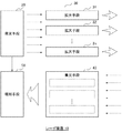
本発明の第1の実施形態について説明する。本実施形態に係るレーザ装置のブロック構成図を図1に示す。図1において、レーザ装置10は、発光手段20、n個の拡大手段30(31、32、…、3n)、集光手段40および報知手段50を備える。
(First embodiment)
A first embodiment of the present invention will be described. A block diagram of the laser apparatus according to the present embodiment is shown in FIG. In FIG. 1, the
発光手段20は、拡大手段30に向けてパルス光を出射する。なお、n個の発光手段20(21、22、…、2n)を用いて、n個の拡大手段31、32、…、3nと1対1に対応するように、n個の発光手段21、22、…、2nを配置することが望ましい。
The light emitting means 20 emits pulsed light toward the
拡大手段30は、発光手段20から入射されたパルス光を所定の広がりを有する光に拡大し、出射光として出射する。拡大手段30としては、例えば、平凹シリンドリカルレンズを適用することができる。本実施形態においては、n個の拡大手段30として、入射されたパルス光を水平角度が60度のファンビームに形成してそれぞれ出射する、6個の平凹シリンドリカルレンズ31、32、…、36を適用した。
The magnifying means 30 magnifies the pulsed light incident from the light emitting means 20 into light having a predetermined spread, and emits it as outgoing light. As the magnifying means 30, for example, a plano-concave cylindrical lens can be applied. In the present embodiment, as the n expanding means 30, six plano-concave
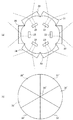
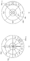
6個の発光手段21、22、…、26および平凹シリンドリカルレンズ31、32、…、36を配置した状態を上方から見た時の一例を図2(a)に、平凹シリンドリカルレンズ31、32、…、36から出射される出射光の出射範囲31’、32’、…、36’を上方から見た時の一例を図2(b)に示す。
FIG. 2 (a) shows an example of a state in which the six light emitting means 21, 22,..., And the plano-concave
図2に示すように、円周上に配置された6個の平凹シリンドリカルレンズ31、32、…、36により、出射光の出射領域が出射面の全周(360度)に亘って分布される。なお、本実施形態では6個の平凹シリンドリカルレンズを円周上に隣接配置したが、出射光の出射領域を出射面上の全周に分布させることができれば、これに限定されない。
As shown in FIG. 2, the emission area of the emitted light is distributed over the entire circumference (360 degrees) of the emission surface by the six plano-concave
集光手段40は、拡大手段30から出射された出射光が障害物において反射された反射光を、報知手段50へ集光する。本実施形態では、集光手段40を6個の平凸シリンドリカルレンズ41、42、…、46によって構成し、平凹シリンドリカルレンズ31、32、…、36と1対1に対応させた。なお、集光手段40は、必ずしも、拡大手段30と1対1に対応させる必要はない。1つの集光手段40で複数の平凹シリンドリカルレンズ31、32、…から出射された出射光の反射光を集光することもできる。
The
報知手段50は、集光手段40によって集光された光に、拡大手段30から出射された出射光が障害物において反射された反射光が含まれているか否かを調査し、反射光が含まれている場合は出射光の出射から反射光が検知されるまでの時間を取得する。さらに、報知手段50は、取得した時間に基づいて障害物までの距離を演算し、演算した距離が所定の閾値よりも小さい場合、アラームを出力する。
The notification means 50 investigates whether or not the light collected by the light collecting means 40 includes the reflected light that is reflected from the obstacle by the light emitted from the
以上のように構成されたレーザ装置10においては、入射されたパルス光を所定の広がりを有するファンビームに形成して出射する拡大手段30(n個の平凹シリンドリカルレンズ)を、出射光が出射面上で全周に亘って出射されるように配置した。出射光の出射領域が出射面の全周(360度)に亘って分布されることから、その反射光を検出することにより、障害物の接近を検出してアラームを出力することができる。
In the
また、本実施形態に係るレーザ装置10において、発光手段20から出射されたパルス光はそのままn個の拡大手段30に入射して所定の広がりを有するパルス光に拡大され、出射光として出射面上の全周方向に出射される。この場合、複数の光学系を配置する必要がなく、装置の構成が単純になる。さらに、複数の光学系間においてパルス光の光路を確保する必要がなく、装置が大きくなるのを回避することができる。
Further, in the
(第2の実施形態)
第2の実施形態について説明する。本実施形態に係るレーザ装置は、例えば、山岳地域において低速運行およびホバリング運行され、救難作業や電線監視作業等を行うヘリに搭載される。本実施形態に係るレーザ装置のブロック構成図を図3に示す。図3において、レーザ装置100は、駆動回路200、水平方向検知部300、垂直方向検知部400、受信アンプ500、制御部600および表示部700を備える。
(Second Embodiment)
A second embodiment will be described. The laser device according to the present embodiment is mounted on a helicopter that performs low speed operation and hovering operation in a mountainous area and performs rescue work, electric wire monitoring work, and the like. FIG. 3 shows a block diagram of the laser apparatus according to the present embodiment. 3, the laser device 100 includes a
駆動回路200は、制御部600から入力した充電信号に基づいて、水平方向検知部300および垂直方向検知部400に配置された電源部310、410にそれぞれ給電を行う。また、駆動回路200は、制御部600から入力した駆動信号に基づいて、水平方向検知部300および垂直方向検知部400に配置されたレーザダイオード(LD:Laser Diode)320、420を発光させる。
The
水平方向検知部300は、例えば、ヘリのローター軸に配置され、ヘリのローターの回転面と平行な面方向にレーザ光を出射し、その反射光を受信する。図3に示すように、本実施形態に係る水平方向検知部300は、それぞれ8つの、電源部310a〜310h、LD320a〜320h、送信用光学系330a〜330h、受信用光学系340a〜340h、および、フォトダイオード(PD:Photodiode)350a〜350hを備える。
The horizontal
電源部310は、駆動回路200から電源が供給され、供給された電源をLD320へ供給する。
The power supply unit 310 is supplied with power from the
LD320は、駆動回路200に駆動されることによって、送信用光学系330に向けてパルスレーザ光を発光する。本実施形態においては、高速運行中の運用を想定しないため、長距離計測用の高出力のレーザ光源を配置する必要がない。従って、容易に入手可能な一般的なLDを適用することができる。
The LD 320 emits pulsed laser light toward the transmission optical system 330 by being driven by the
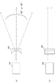
送信用光学系330は、例えば、平凹シリンドリカルレンズが適用され、LD320から入射したパルスレーザ光を所定の角度を有するファンビーム(扇型ビーム)に整形して外部空間へ出射する。送信用光学系330から出射されたファンビームを上方から見た時の図を図4(a)に、側方から見た時の図を図4(b)に示す。 For example, a plano-concave cylindrical lens is applied to the transmission optical system 330, and the pulse laser beam incident from the LD 320 is shaped into a fan beam (fan beam) having a predetermined angle and emitted to the external space. FIG. 4A shows a view when the fan beam emitted from the transmission optical system 330 is viewed from above, and FIG. 4B shows a view when the fan beam is viewed from the side.
本実施形態では、8つの送信用光学系330a〜330hを円筒体の外周に配置してヘリのローター軸に配置する。送信用光学系330をヘリの後方から見た時の外観図を図5(a)に、前方から見た時の外観図を図5(b)に示す。図5に示すように、本実施形態では、パイロットが目視によって障害物の接近を確認しにくいヘリの後方側に、6つの送信用光学系330a〜330fを配置する。一方、パイロットが目視によって障害物の接近を確認できるヘリの前方側に、2つの送信用光学系330g、330hを配置する。そして、ヘリの後方側に配置した送信用光学系330a〜330fからは30度の広がりを持つファンビームが出射される。また、ヘリの前方側に配置した送信用光学系330g、330hからは90度の広がりを持つファンビームが出射される。
In this embodiment, eight transmission
送信用光学系330a〜330hから出射したファンビームを上方(A方向)から見た時の図を図6の左側に示す(A方向)。図6のA方向の図に示すように、LD320a〜320fから発光されたパルスレーザ光を送信用光学系330a〜330fによってそれぞれ水平方向に30度に広がるファンビーム360a〜360fに形成して出射し、LD320g、320hから発光されたパルスレーザ光を送信用光学系330g、330hによってそれぞれ水平方向に90度に広がるファンビーム360g、360hに形成して出射することにより、ファンビームが360度全水平方向に出射される。
A view of the fan beam emitted from the transmitting
図3の説明に戻る。受信用光学系340は、例えば、平凸シリンドリカルレンズが適用され、受信用光学系340に入射した光をPD350に集光する。受信用光学系340は送信用光学系330と対応付けて配置される。図5に、受信用光学系340も併せて示す。図5に示すように、ヘリの後方側において、6つの送信用光学系330a〜330fの下方に6つの受信用光学系340a〜340fが配置され、前方側において、送信用光学系330g、330hの下方に受信用光学系340g、340hが配置される。
Returning to the description of FIG. For example, a plano-convex cylindrical lens is applied to the reception optical system 340, and the light incident on the reception optical system 340 is condensed on the PD 350. The receiving optical system 340 is disposed in association with the transmitting optical system 330. FIG. 5 also shows the receiving optical system 340. As shown in FIG. 5, six receiving
PD350a〜350hはそれぞれ、受信用光学系340a〜340hによって集光された光を電気信号に変換し、受信信号として受信アンプ500へ出力する。本実施形態において、PD350は、送信用光学系330から出射されたファンビームが障害物等によって反射された反射光を検出して受信信号を出力する。
Each of the PDs 350a to 350h converts the light collected by the receiving
垂直方向検知部400は、例えば、ヘリの尾翼に配置され、ヘリのローターの回転面と垂直な面方向にレーザ光を出射し、その反射光を受信する。なお、垂直方向検知部400をヘリの先端に配置したり、垂直方向検知部400を分割してヘリの上面および下面に配置したりすることもできる。垂直方向検知部400は、それぞれ4つの、電源部410a〜410d、LD420a〜420d、送信用光学系430a〜430d、受信用光学系440a〜440d、PD450a〜450dを備える。
For example, the vertical
垂直方向検知部400の電源部410、LD420、送信用光学系430、受信用光学系440およびPD450はそれぞれ、水平方向検知部300の電源部310、LD320、送信用光学系330、受信用光学系340およびPD350と同様に機能する。
The power supply unit 410, LD420, transmission optical system 430, reception optical system 440, and PD 450 of the vertical
4つの送信用光学系430a〜430dからはそれぞれ、ヘリの上方、左側方、右側方および下方に、90度に広がるファンビームが出射される。4つの送信用光学系430a〜430dから出射されたファンビームを後方から見た時の図を図6右側に示す(B方向)。
From the four transmission
図6のB方向の図に示すように、LD420a〜420dから発光されたパルスレーザ光を送信用光学系430a〜430dによってそれぞれ90度に広がるファンビーム460a〜460dに形成して出射することにより、ファンビームが360度全垂直方向に出射される。
As shown in the diagram in the B direction of FIG. 6, by forming and emitting the pulse laser light emitted from the
そして、受信用光学系440a〜440dは送信用光学系430a〜430dから出射されたファンビームの反射光をPD450a〜450dに集光し、PD450a〜450dは集光された光を電気信号に変換し、受信信号として受信アンプ500へ出力する。
The receiving
受信アンプ500には、水平方向検知部300および垂直方向検知部400からそれぞれ、ファンビームの反射光の受信信号(電気信号)が入力する。受信アンプ500は、入力した受信信号を増幅して制御部600へ出力する。
A reception signal (electric signal) of the reflected light of the fan beam is input to the
制御部600は、駆動回路200に対して充電信号および駆動信号を送信する。また、制御部600は、受信アンプ500から入力した受信信号に基づいて接近している障害物の有無を判断する。例えば、制御部600は、受信アンプ500から入力した受信信号のうち所定の閾値よりも大きな出力を有する受信信号を障害物からの反射光であると判断する。制御部600は、反射光を検知した場合、駆動回路200に対して駆動信号を送信した時から反射光が入力した時までの時間を取得し、ヘリの周囲にある障害物までの距離を算出する。そして、制御部600は、所定の閾値よりも短い距離に障害物が位置していると判断した場合、表示部700にアラームを表示するための画面表示信号を出力する。
The
表示部700はヘリのコックピット等の操縦者が目視可能な場所に配置され、制御部600から入力した画面表示信号に基づいてアラーム表示する。ヘリの進行方向に向かって右側後方に障害物が接近している場合の表示部700の一例を図7に示す。なお、図7(a)は水平方向表示、図7(b)は垂直方向表示である。ヘリの操縦者が表示部700に表示されたアラームを確認して左側前方にヘリを移動させることにより、ヘリが障害物に接触することを避けることができる。
The
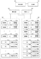
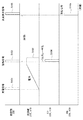
上記のように構成されたレーザ装置100の動作手順について説明する。レーザ装置100から送受信される信号等のタイムチャートを図8に示す。図8は、上から順番に、制御部600から出力される各種信号、電源部310、410に蓄積された電力、LD320、420から発光されたパルスレーザ光、PD350、450において検出した受信信号である。
An operation procedure of the laser apparatus 100 configured as described above will be described. A time chart of signals transmitted and received from the laser apparatus 100 is shown in FIG. FIG. 8 shows, in order from the top, various signals output from the
図8において、制御部600から充電信号が出力されることにより(S101)、駆動回路200は、水平方向検知部300および垂直方向検知部400に配置された電源部310、410への給電を開始する(S102)。
In FIG. 8, when a charge signal is output from the control unit 600 (S101), the
電源部310、410が十分電力を蓄えた状態で制御部600から駆動信号が出力されることにより(S103)、水平方向検知部300および垂直方向検知部400に配置されたLD320、420からパルスレーザ光が発光される(S104)。LD320、420から発光されたパルスレーザ光は平凹シリンドリカルレンズが適用された送信用光学系330、430によって所定の広がりを有するファンビームに形成されて出射される。
When the drive signal is output from the
この時、水平方向検知部300においては、ヘリの後方に配置された送信用光学系330a〜330fから水平方向に30度に広がるファンビームが、ヘリの前方に配置された送信用光学系330g、330hから水平方向に90度に広がるファンビームが出射されることによって、パルスレーザ光が360度全水平方向に出射される。一方、垂直方向検知部400においては、4つの送信用光学系430a〜430dから垂直方向に90度に広がるファンビームがそれぞれ出射されることによって、パルスレーザ光が360度全垂直方向に出射される。
At this time, in the horizontal
そして、ヘリの周囲に障害物(森林、電線、山斜面等)があった場合、水平方向検知部300および垂直方向検知部400から出射されたファンビームは障害物によって反射され、受信用光学系340、440によってPD350、450に集光される。PD350、450は、集光された反射光を受信信号として出力する(S105)。
When there are obstacles (forests, electric wires, mountain slopes, etc.) around the helicopter, the fan beams emitted from the horizontal
複数の送信用光学系330a〜330h、430a〜430dおよび複数の受信用光学系340a〜340h、440a〜440dを配置して測定チャンネルを細分化することにより、機械的駆動を用いることなくヘリの全周方向にパルスレーザ光を出射でき、全周方向にパルスレーザ光を繰り返し出射することが容易にできる。
By arranging a plurality of transmission
制御部600は、駆動信号を出力した時から受信信号が入力するまでの時間tを計測することにより、ローターまたは尾翼と障害物との距離を演算する。制御部600はさらに、演算結果から、所定の閾値よりも短い距離に障害物が位置していると判断した場合、表示部700にアラームを表示するための画面表示信号を出力する(S106)。画面表示信号に基づいて表示部700にアラームが表示されることにより、ヘリの操縦者はヘリに障害物が接近していることを認識する。
The
以上のように、本実施形態に係るレーザ装置100は、水平方向については8つの平凹シリンドリカルレンズを用いてパルスレーザ光を360度全水平方向に出射すると共に、垂直方向については4つの平凹シリンドリカルレンズを用いてパルスレーザ光を360度全垂直方向に出射する。パルスレーザ光を全周に亘って出射してその反射光を検出することにより、ヘリに接近する障害物を全方向について監視することができる。 As described above, the laser apparatus 100 according to the present embodiment emits pulsed laser light in 360 degrees all horizontal directions using eight plano-concave cylindrical lenses in the horizontal direction and four plano-concaves in the vertical direction. Using a cylindrical lens, pulse laser light is emitted 360 degrees in all vertical directions. An obstacle approaching the helicopter can be monitored in all directions by emitting pulsed laser light over the entire circumference and detecting the reflected light.
また、本実施形態に係るレーザ装置100は、複数光学系の配置を必要としない単純な構成を適用することができると共に、複数の光学系間においてパルス光の光路を確保する必要がないため、装置が大きくなるのを避けることができる。 Further, the laser apparatus 100 according to the present embodiment can apply a simple configuration that does not require the arrangement of a plurality of optical systems, and does not need to secure an optical path of pulsed light between the plurality of optical systems. It is possible to avoid the device becoming large.
ここで、ヘリの後方に可視カメラを配置し、アラームを表示する場合、可視カメラによって該当範囲を撮影した映像を表示部700に重畳することにより、障害物をさらに認識しやすくできる。 Here, when a visible camera is arranged behind the helicopter and an alarm is displayed, an obstacle can be more easily recognized by superimposing on the display unit 700 a video obtained by photographing the corresponding range with the visible camera.
本願発明は上記実施形態に限定されるものではなく、この発明の要旨を逸脱しない範囲の設計の変更等があってもこの発明に含まれる。 The present invention is not limited to the above-described embodiment, and design changes and the like within a range not departing from the gist of the present invention are included in the present invention.
10 レーザ装置
20 発光手段
30 拡大手段
31、32、…、36 平凹シリンドリカルレンズ
40 集光手段
41、42、…、46 平凸シリンドリカルレンズ
50 報知手段
100 レーザ装置
200 駆動回路
300 水平方向検知部
310a〜310h 電源部
320a〜320h LD
330a〜330h 送信用光学系
340a〜340h 受信用光学系
350a〜350h PD
400 垂直方向検知部
410a〜410d 電源部
420a〜420d LD
430a〜430d 送信用光学系
440a〜440d 受信用光学系
450a〜450d PD
500 受信アンプ
600 制御部
700 表示部
DESCRIPTION OF
330a to 330h Transmission
400 Vertical
430a to 430d Transmission
500
Claims (8)
前記出射されたパルス光がそれぞれ入射し、入射したパルス光を所定の広がりを有するパルス光に拡大して出射光としてそれぞれ出射するn個の拡大手段と、
入射した光を集光する集光手段と、
前記集光された光に前記出射光が検知対象によって反射された反射光が含まれていることを検知し、前記出射光の出射から前記検知までにかかった時間に基づいて前記検知対象までの距離を演算し、演算した距離が所定の閾値よりも小さい場合に報知する報知手段と、
を備え、
前記出射光は、前記n個の拡大手段30によって所定の面上の全周方向に出射されることを特徴とするレーザ装置。 Light emitting means for emitting pulsed light;
Each of the emitted pulsed light is incident, the incident pulsed light is expanded into pulsed light having a predetermined spread, and each of the n expanding means emits the emitted light as outgoing light,
Condensing means for condensing incident light;
Detecting that the condensed light includes reflected light reflected by the detection target in the collected light, and detecting the detection target based on the time taken from the emission of the emission light to the detection. A notifying means for calculating a distance and notifying when the calculated distance is smaller than a predetermined threshold;
With
The emitted light is emitted in the entire circumferential direction on a predetermined surface by the n number of enlargement means 30.
前記集光手段は、前記n個の拡大手段とそれぞれ対応配置されたn個の平凸シリンドリカルレンズによって構成される、
請求項1記載のレーザ装置。 The magnifying means is a plano-concave cylindrical lens;
The condensing means is constituted by n plano-convex cylindrical lenses respectively arranged corresponding to the n enlargement means.
The laser device according to claim 1.
入射したパルス光を30度の広がりを有するファンビームに形成して出射する6個の第1平凹シリンドリカルレンズと、
入射したパルス光を90度の広がりを有するファンビームに形成して出射する2個の第2平凹シリンドリカルレンズと、
により構成される、請求項2記載のレーザ装置。 The enlargement means includes
Six first plano-concave cylindrical lenses that form and emit incident pulsed light into a fan beam having a 30-degree spread;
Two second plano-concave cylindrical lenses that form and emit incident pulsed light into a fan beam having a 90-degree spread;
The laser device according to claim 2, comprising:
前記所定の面は、前記ローターの回転面と平行な面である、
請求項1乃至3のいずれか1項記載のレーザ装置。 The n expanding means are arranged on the rotor shaft of the helicopter in a state of being arranged in parallel on the circumference,
The predetermined surface is a surface parallel to the rotation surface of the rotor.
The laser device according to any one of claims 1 to 3.
前記m個の第2拡大手段は、円周上に並列配置された状態でヘリコプターの尾翼に配置され、
前記m個の第2拡大手段からの出射光は、ローターの回転面と直交する面上の全周方向に出射される、
請求項4記載のレーザ装置。 Each of the pulsed light is incident, and further includes m second expanding means for expanding the incident pulsed light into pulsed light having a predetermined spread and emitting each as outgoing light,
The m second expansion means are arranged on the helicopter tail in a state of being arranged in parallel on the circumference,
The emitted light from the m second magnifying means is emitted in the entire circumferential direction on the surface orthogonal to the rotation surface of the rotor.
The laser device according to claim 4.
前記報知手段は演算した距離が所定の閾値よりも小さい場合に前記表示手段にアラーム表示する、
請求項1乃至6のいずれか1項記載のレーザ装置。 It further comprises display means arranged at a place where the user can visually recognize,
The notification means displays an alarm on the display means when the calculated distance is smaller than a predetermined threshold;
The laser device according to claim 1.
前記表示手段は、前記可視カメラの撮像データと前記アラーム表示とを重畳して表示する、
請求項7記載のレーザ装置。 It further comprises a visible camera that captures the area around the helicopter,
The display means superimposes and displays the imaging data of the visible camera and the alarm display.
The laser device according to claim 7.
Priority Applications (1)
| Application Number | Priority Date | Filing Date | Title |
|---|---|---|---|
| JP2013257939A JP2015114257A (en) | 2013-12-13 | 2013-12-13 | Laser device |
Applications Claiming Priority (1)
| Application Number | Priority Date | Filing Date | Title |
|---|---|---|---|
| JP2013257939A JP2015114257A (en) | 2013-12-13 | 2013-12-13 | Laser device |
Publications (1)
| Publication Number | Publication Date |
|---|---|
| JP2015114257A true JP2015114257A (en) | 2015-06-22 |
Family
ID=53528175
Family Applications (1)
| Application Number | Title | Priority Date | Filing Date |
|---|---|---|---|
| JP2013257939A Pending JP2015114257A (en) | 2013-12-13 | 2013-12-13 | Laser device |
Country Status (1)
| Country | Link |
|---|---|
| JP (1) | JP2015114257A (en) |
Cited By (5)
| Publication number | Priority date | Publication date | Assignee | Title |
|---|---|---|---|---|
| WO2018230552A1 (en) * | 2017-06-13 | 2018-12-20 | 川崎重工業株式会社 | Aircraft hovering operation assist system, and aircraft comprising same |
| EP3491419A4 (en) * | 2016-08-26 | 2019-11-27 | SZ DJI Technology Co., Ltd. | Optical structure for extending laser radar scanning range of uavs and other objects, and associated systems and methods |
| JP2020185996A (en) * | 2017-06-13 | 2020-11-19 | 川崎重工業株式会社 | Aircraft hovering work support system and aircraft with the same |
| JPWO2022019242A1 (en) * | 2020-07-22 | 2022-01-27 | ||
| JP2023002982A (en) * | 2021-06-23 | 2023-01-11 | 株式会社リコー | Distance measuring device and distance measuring system |
-
2013
- 2013-12-13 JP JP2013257939A patent/JP2015114257A/en active Pending
Cited By (10)
| Publication number | Priority date | Publication date | Assignee | Title |
|---|---|---|---|---|
| EP3491419A4 (en) * | 2016-08-26 | 2019-11-27 | SZ DJI Technology Co., Ltd. | Optical structure for extending laser radar scanning range of uavs and other objects, and associated systems and methods |
| WO2018230552A1 (en) * | 2017-06-13 | 2018-12-20 | 川崎重工業株式会社 | Aircraft hovering operation assist system, and aircraft comprising same |
| JP2019001246A (en) * | 2017-06-13 | 2019-01-10 | 川崎重工業株式会社 | Aircraft hovering work support system, and aircraft comprising the same |
| JP2020185996A (en) * | 2017-06-13 | 2020-11-19 | 川崎重工業株式会社 | Aircraft hovering work support system and aircraft with the same |
| US11377226B2 (en) | 2017-06-13 | 2022-07-05 | Kawasaki Jukogyo Kabushiki Kaisha | Aircraft hovering work support system and aircraft including same |
| US11840355B2 (en) | 2017-06-13 | 2023-12-12 | Kawasaki Jukogyo Kabushiki Kaisha | Aircraft hovering work support system and aircraft including same |
| JPWO2022019242A1 (en) * | 2020-07-22 | 2022-01-27 | ||
| JP7446430B2 (en) | 2020-07-22 | 2024-03-08 | 京セラ株式会社 | circuit board |
| JP2023002982A (en) * | 2021-06-23 | 2023-01-11 | 株式会社リコー | Distance measuring device and distance measuring system |
| JP7703915B2 (en) | 2021-06-23 | 2025-07-08 | 株式会社リコー | Distance measuring device and system |
Similar Documents
| Publication | Publication Date | Title |
|---|---|---|
| EP2921877B1 (en) | Object detection device and remote sensing apparatus | |
| KR101391298B1 (en) | Three dimensional laser scanning system | |
| US11009606B2 (en) | Laser radar device and traveling body | |
| US10591602B2 (en) | Object detector and sensor | |
| US9891432B2 (en) | Object detection device and sensing apparatus | |
| CN105393138B (en) | Opto-electronic detection device and method for scanning the surroundings of a motor vehicle | |
| CN103608696B (en) | 3D scanning system and method for obtaining 3D images | |
| KR101357051B1 (en) | Three dimensional scanning system and three dimensional image acqusition method using the same | |
| CN110118959B (en) | Photoelectric sensor and method for detecting object in monitoring area | |
| JP6671629B2 (en) | Object detection device, sensing device, and mobile device | |
| JP2015114257A (en) | Laser device | |
| JP6465382B2 (en) | Object detection device and sensing device | |
| CN110082771B (en) | Photoelectric sensor and method for detecting object | |
| CN112034486B (en) | Laser radar and control method of laser radar | |
| JP2016180623A (en) | Laser radar device and traveling body | |
| CN105143820A (en) | Depth scanning with multiple emitters | |
| JP6531502B2 (en) | Optical scanning device, object detection device and sensing device | |
| US11703572B2 (en) | Component assembly for a lidar sensor, and lidar sensor | |
| US20190011539A1 (en) | Light Projecting/Reception Unit And Radar | |
| EP3834004A1 (en) | Methods and systems for dithering active sensor pulse emissions | |
| WO2017183530A1 (en) | Object detection device | |
| KR20190066220A (en) | 3-dimensional lidar device and distance measuring method | |
| Nugent Jr et al. | Low-latency enhanced light curtain for safe laser power beaming | |
| KR20190071998A (en) | Lidar apparatus for vehicle | |
| CN113721220A (en) | Method for realizing two-dimensional optical scanning by single-degree-of-freedom rotation |