JP2015114236A - Fluid machinery and method of manufacturing the same - Google Patents
Fluid machinery and method of manufacturing the same Download PDFInfo
- Publication number
- JP2015114236A JP2015114236A JP2013257251A JP2013257251A JP2015114236A JP 2015114236 A JP2015114236 A JP 2015114236A JP 2013257251 A JP2013257251 A JP 2013257251A JP 2013257251 A JP2013257251 A JP 2013257251A JP 2015114236 A JP2015114236 A JP 2015114236A
- Authority
- JP
- Japan
- Prior art keywords
- conductive
- hole
- fluid
- shield
- working fluid
- Prior art date
- Legal status (The legal status is an assumption and is not a legal conclusion. Google has not performed a legal analysis and makes no representation as to the accuracy of the status listed.)
- Pending
Links
- 239000012530 fluid Substances 0.000 title claims abstract description 83
- 238000004519 manufacturing process Methods 0.000 title claims abstract description 13
- 239000011810 insulating material Substances 0.000 claims abstract 2
- 230000002093 peripheral effect Effects 0.000 claims description 20
- 239000004020 conductor Substances 0.000 claims description 11
- 238000000034 method Methods 0.000 claims description 10
- 239000000463 material Substances 0.000 claims description 9
- 239000012777 electrically insulating material Substances 0.000 claims description 5
- 239000000853 adhesive Substances 0.000 abstract description 21
- 230000001070 adhesive effect Effects 0.000 abstract description 21
- 238000011144 upstream manufacturing Methods 0.000 description 5
- 230000008859 change Effects 0.000 description 3
- 230000003287 optical effect Effects 0.000 description 3
- 230000015572 biosynthetic process Effects 0.000 description 2
- 238000001514 detection method Methods 0.000 description 2
- 239000007788 liquid Substances 0.000 description 2
- 238000003754 machining Methods 0.000 description 2
- 229910052751 metal Inorganic materials 0.000 description 2
- 239000002184 metal Substances 0.000 description 2
- 230000008569 process Effects 0.000 description 2
- 239000000126 substance Substances 0.000 description 2
- 241000191291 Abies alba Species 0.000 description 1
- OKTJSMMVPCPJKN-UHFFFAOYSA-N Carbon Chemical compound [C] OKTJSMMVPCPJKN-UHFFFAOYSA-N 0.000 description 1
- RYGMFSIKBFXOCR-UHFFFAOYSA-N Copper Chemical compound [Cu] RYGMFSIKBFXOCR-UHFFFAOYSA-N 0.000 description 1
- BQCADISMDOOEFD-UHFFFAOYSA-N Silver Chemical compound [Ag] BQCADISMDOOEFD-UHFFFAOYSA-N 0.000 description 1
- 238000010521 absorption reaction Methods 0.000 description 1
- 229910052782 aluminium Inorganic materials 0.000 description 1
- XAGFODPZIPBFFR-UHFFFAOYSA-N aluminium Chemical compound [Al] XAGFODPZIPBFFR-UHFFFAOYSA-N 0.000 description 1
- 230000002238 attenuated effect Effects 0.000 description 1
- 229910052799 carbon Inorganic materials 0.000 description 1
- 239000003795 chemical substances by application Substances 0.000 description 1
- 239000003086 colorant Substances 0.000 description 1
- 229910052802 copper Inorganic materials 0.000 description 1
- 239000010949 copper Substances 0.000 description 1
- 230000007423 decrease Effects 0.000 description 1
- 238000010586 diagram Methods 0.000 description 1
- 238000009826 distribution Methods 0.000 description 1
- 230000005611 electricity Effects 0.000 description 1
- 238000000605 extraction Methods 0.000 description 1
- PCHJSUWPFVWCPO-UHFFFAOYSA-N gold Chemical compound [Au] PCHJSUWPFVWCPO-UHFFFAOYSA-N 0.000 description 1
- 229910052737 gold Inorganic materials 0.000 description 1
- 239000010931 gold Substances 0.000 description 1
- 230000009545 invasion Effects 0.000 description 1
- 230000001678 irradiating effect Effects 0.000 description 1
- 239000000203 mixture Substances 0.000 description 1
- 230000004048 modification Effects 0.000 description 1
- 238000012986 modification Methods 0.000 description 1
- 238000000465 moulding Methods 0.000 description 1
- 230000035515 penetration Effects 0.000 description 1
- 239000011347 resin Substances 0.000 description 1
- 229920005989 resin Polymers 0.000 description 1
- 230000004044 response Effects 0.000 description 1
- 229910052709 silver Inorganic materials 0.000 description 1
- 239000004332 silver Substances 0.000 description 1
- 238000007711 solidification Methods 0.000 description 1
- 230000008023 solidification Effects 0.000 description 1
- 238000005507 spraying Methods 0.000 description 1
- 239000011800 void material Substances 0.000 description 1
Images

Landscapes
- Aerodynamic Tests, Hydrodynamic Tests, Wind Tunnels, And Water Tanks (AREA)
Abstract
Description
本発明は、作動流体の物理量を検出するセンサを有する流体機器及び流体機器の製造方法に関する。 The present invention relates to a fluid device having a sensor for detecting a physical quantity of a working fluid and a method for manufacturing the fluid device.
構造物の表面における作動流体の物理量を計測する手段の一つとして、構造物の表面に孔を形成し、その孔から作動流体を取り出し、取り出した先で該作動流体の物理量の検出、計測を行う方法が知られている。
例えば、飛行機の主翼表面の圧力分布を測定するための技術として、翼の表面に開口する多数の小孔と、これらの小孔を翼根に連通させる通路とを相互に干渉しないように配置した風洞試験用模型が知られている(特許文献1)。
As one means of measuring the physical quantity of the working fluid on the surface of the structure, a hole is formed in the surface of the structure, the working fluid is taken out from the hole, and the physical quantity of the working fluid is detected and measured at the destination. How to do is known.
For example, as a technique for measuring the pressure distribution on the surface of the main wing of an airplane, a large number of small holes that open on the surface of the wing and a passage that communicates these small holes with the blade root are arranged so as not to interfere with each other. A wind tunnel test model is known (Patent Document 1).
ところで、構造物表面の孔から作動流体を取り出し、取り出した先で作動流体の物理量の検出、計測を行うと、その間に作動流体の物理量が変化してしまい、構造物表面における物理量を正しく知ることができない場合がある。例えば、構造物表面の圧力変動を計測する場合、圧力変動が孔内を伝わる間に減衰してしまい、取り出した先で計測した作動流体の圧力変動は、構造物表面における実際の変動よりも小さくなってしまう。 By the way, if the working fluid is taken out from the hole on the surface of the structure and the physical quantity of the working fluid is detected and measured at the tip, the physical quantity of the working fluid changes during that time, so that the physical quantity on the structure surface can be known correctly. May not be possible. For example, when measuring pressure fluctuations on the surface of a structure, the pressure fluctuations are attenuated while passing through the hole, and the pressure fluctuations of the working fluid measured at the point of extraction are smaller than the actual fluctuations on the surface of the structure. turn into.
本発明はこのような課題に鑑みてなされたものであって、作動流体の物理量をより精度高く検出することができる流体機器及び流体機器の製造方法を提供することを目的としている。 This invention is made | formed in view of such a subject, Comprising: It aims at providing the manufacturing method of the fluid apparatus and the fluid apparatus which can detect the physical quantity of a working fluid more accurately.
上記課題を解決するため、本発明の一態様として以下の手段が提供される。
即ち、本発明に係る一態様としての流体機器は、第一端が作動流体に接触する第一面に開口するとともに該第一端とは反対側の第二端が第一面とは異なる第二面に開口する導電用孔部が形成され、電気絶縁性の材料から形成された機器本体と、前記導電用孔部内を充填するように設けられて、流動性を有する電気伝導材料を固化することで形成された導電部と、前記導電部に第一面側から接続され、前記作動流体の物理量を検出するセンサと、前記導電部に第二面側から接続された導線と、を備えることを特徴とする。
当該流体機器によれば、センサが作動流体の物理量を機器本体の第一面側で検出し、この検出値は導電部及び導線を介して外部に出力される。したがって、作動流体の物理量に変動が生じた場合でも、当該物理量に対応する検出値が精度高く出力される。
In order to solve the above problems, the following means are provided as one aspect of the present invention.
That is, in the fluid device as one aspect according to the present invention, the first end opens on the first surface that contacts the working fluid, and the second end opposite to the first end is different from the first surface. Conductive holes that are open on two surfaces are formed, and the device main body formed of an electrically insulating material and the conductive holes are provided so as to fill the inside of the conductive holes to solidify the electrically conductive material having fluidity. A conductive portion formed from the first surface side and connected to the conductive portion from the first surface side to detect a physical quantity of the working fluid; and a conductive wire connected to the conductive portion from the second surface side. It is characterized by.
According to the fluid device, the sensor detects the physical quantity of the working fluid on the first surface side of the device body, and the detected value is output to the outside through the conductive portion and the conductive wire. Therefore, even when the physical quantity of the working fluid varies, the detection value corresponding to the physical quantity is output with high accuracy.
また、本発明に係る流体機器において、前記センサは、前記導電部に挿し込まれる凸状の端子を有していてもよい。
これにより、端子が導電部へ挿し込まれるだけでセンサと導電部が接続されるため、センサと導電部の接続作業がより簡単となる。
Moreover, the fluid apparatus which concerns on this invention WHEREIN: The said sensor may have a convex-shaped terminal inserted in the said electroconductive part.
Thereby, since the sensor and the conductive part are connected only by inserting the terminal into the conductive part, the connection work between the sensor and the conductive part becomes easier.
また、本発明に係る流体機器において、前記導電部に伴って延びて前記導電部への電磁波を遮蔽するシールド部を備えていてもよい。
これにより、導電部への外乱としての電磁波の侵入が抑制されるため、作動流体の物理量に対応する検出値をより高い精度で出力することができる。
The fluid device according to the present invention may include a shield portion that extends along with the conductive portion and shields electromagnetic waves to the conductive portion.
Thereby, since the penetration | invasion of the electromagnetic wave as a disturbance to an electroconductive part is suppressed, the detection value corresponding to the physical quantity of a working fluid can be output with a higher precision.
また、本発明に係る流体機器において、前記機器本体に、前記導電用孔部を該導電用孔部の外周側から囲うように延びるシールド用孔部が形成され、前記シールド部は、前記シールド用孔部を充填するように設けられた流動性を有する電気伝導材料を固化することで形成されていてもよい。
これにより、導電部と同様の形成過程によりシールド部を形成することができる。
Further, in the fluid device according to the present invention, a shield hole extending so as to surround the conductive hole from an outer peripheral side of the conductive hole is formed in the device main body, and the shield portion is the shield It may be formed by solidifying an electrically conductive material having fluidity provided so as to fill the hole.
Thereby, a shield part can be formed by the formation process similar to an electroconductive part.
また、本発明に係る流体機器において、前記シールド部は、前記導電用孔部の内周面と前記導電部の外周面の間に介在された電磁遮蔽材料によって形成されていてもよい。
これにより、シールド部を設けるために機器本体に形成する孔部の数を削減することができる。なお、上記電磁遮蔽材料は、孔部内周面に吹き付け等によってコーティングされるものであってもよい。
Moreover, the fluid apparatus which concerns on this invention WHEREIN: The said shield part may be formed with the electromagnetic shielding material interposed between the inner peripheral surface of the said hole for conduction | electrical_connection, and the outer peripheral surface of the said electroconductive part.
Thereby, in order to provide a shield part, the number of the hole parts formed in an apparatus main body can be reduced. The electromagnetic shielding material may be coated on the inner peripheral surface of the hole by spraying or the like.
また、本発明に係る流体機器において、前記導電用孔部は前記機器本体に複数形成されており、前記導電部は、これら複数の導電用孔部のそれぞれに設けられて、前記導電用孔部毎に互いに異なる色彩であってもよい。
これにより、信号線としての導電部の識別性が向上し、導電部と導線の接続作業におけるミスを抑制することができる。
Further, in the fluid device according to the present invention, a plurality of the conductive hole portions are formed in the device main body, and the conductive portion is provided in each of the plurality of conductive hole portions, and the conductive hole portion is provided. The colors may be different from one another.
Thereby, the distinguishability of the conductive part as the signal line is improved, and errors in the connection work between the conductive part and the conductive wire can be suppressed.
また、本発明に係る一態様としての流体機器の製造方法は、第一端が作動流体に接触する第一面に開口するとともに該第一端とは反対側の第二端が第一面とは異なる第二面に開口する孔部が形成されている機器本体を電気絶縁性の材料から形成するステップと、前記孔部内に、流動性を有する電気伝導材料を充填して該電気伝導材料を固化させることで導電部を形成するステップと、を備える。 Further, in the fluid device manufacturing method as one aspect according to the present invention, the first end opens on the first surface contacting the working fluid, and the second end opposite to the first end is the first surface. Forming a device main body having holes formed on different second surfaces from an electrically insulating material, and filling the holes with an electrically conductive material having fluidity to provide the electrically conductive material. Forming a conductive portion by solidifying.
さらに、本発明にかかる流体機器の製造方法は、前記第一面に、前記作動流体の物理量を検出するセンサを取り付けるステップと、前記導電部に、第二面側から導線を接続するステップと、を備えていてもよい。
当該流体機器の製造方法によれば、導電部が孔部内における信号線として機能するため、孔部内に導線を配線する作業が不要となる。
Furthermore, the manufacturing method of the fluid device according to the present invention includes a step of attaching a sensor for detecting a physical quantity of the working fluid to the first surface, a step of connecting a conductive wire from the second surface side to the conductive portion, May be provided.
According to the manufacturing method of the fluid device, since the conductive portion functions as a signal line in the hole portion, an operation of wiring a conductive wire in the hole portion is not necessary.
また、本発明に係る流体機器の製造方法において、前記機器本体は、光造形によって形成されてもよい。
これにより、孔部が形成されている機器本体は一体成形により形成される。したがって、機器本体に対し機械加工等により孔部を形成する場合と比較して、容易に形成することができる。
In the method for manufacturing a fluid device according to the present invention, the device main body may be formed by stereolithography.
Thereby, the apparatus main body in which the hole is formed is formed by integral molding. Therefore, it can be easily formed as compared with the case where the hole is formed in the apparatus main body by machining or the like.
本発明の流体機器及び流体機器の製造方法によれば、作動流体の物理量をより精度高く検出することができる。 According to the fluid device and the fluid device manufacturing method of the present invention, the physical quantity of the working fluid can be detected with higher accuracy.
次に、本発明の第1実施形態ついて、図1から図3を参照して説明する。
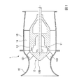
図1は本実施形態における流体機器1の断面図である。流体機器1は、例えば光造形により電気絶縁性の材料から形成された試験用の流体機器である。
ここで、光造形とは、光に反応し硬化する液体へ光を照射し硬化させ、積層することで構造物を成形する造形手法である。これにより、基本構造物を成形した後機械加工等を施さなければ成形できない複雑な構造物であっても、容易に一体成形することができる。
Next, a first embodiment of the present invention will be described with reference to FIGS.
FIG. 1 is a cross-sectional view of a fluid device 1 in the present embodiment. The fluid device 1 is a test fluid device formed from an electrically insulating material by, for example, stereolithography.
Here, the optical modeling is a modeling technique in which a structure is formed by irradiating light to a liquid that cures in response to light and curing the liquid. As a result, even a complicated structure that cannot be formed unless the basic structure is formed and then machined or the like can be formed easily.
流体機器1は、略円筒形状のケーシング10と、ケーシング10と同軸上に配置された主軸11と、主軸11の上流端に固定されたインペラ(機器本体)12と、インペラ12の下流端に隣接されて主軸11の中途部が貫通するディフューザハブ13と、ケーシング10の軸線方向略全幅に跨る案内羽根14と、ケーシング10の上流側に接続された吸込ベルマウス15と、を備えている。
The fluid device 1 is adjacent to a substantially
ケーシング10は、インペラ12の周囲を覆うと共に上流側に開口する吸込ベルマウス15の下流側を接続しており、案内羽根14の上流側端から下流側端に跨って略円筒形状とされている。
The
インペラ12は、上流側軸心付近を頂点とする略円錐形状のインペラハブ120と、インペラハブ120に固定された複数のインペラ翼121と、を備えている。また、インペラハブ120には、主軸11の一端が接続されている。尚、主軸11の他端は図示しない駆動モータ等が接続され、この駆動モータ等により主軸11が回転するとインペラ12が一体的に回転するように構成されている。
The
ディフューザハブ13は、インペラ12の下流側に隣接されており、主軸11が貫通すると共にインペラ12と主軸11の回転を許容している。
The
案内羽根14は、ケーシング10又はディフューザハブ13と一体に形成されており、ケーシング10の内面とディフューザハブ13の外周とに跨っている。
The
このような構成において、流体機器1は、駆動モータの駆動によって主軸11とインペラ12とが一体に回転すると共に、吸込ベルマウス15から吸い込まれた流体が、インペラ12の回転により圧力上昇した後に、案内羽根14によって整流されつつ下流側へと吐き出される。
In such a configuration, in the fluid device 1, the
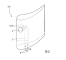
図2は、インペラ翼121の斜視図である。インペラ翼121には、作動流体接触面に一端が開口し、他端がインペラハブ120に固定される翼根部分において開口する導電用孔部1210が2つ形成されている。インペラ翼121は、光造形により、あらかじめ導電用孔部1210が形成された状態へ一体成形されることにより製造される。
FIG. 2 is a perspective view of the
導電用孔部1210には、その内部を充填されるように導電性接着剤(流動性を有する電気伝導材料)で形成された導電部3が設けられている。ここで、導電性接着剤とは、樹脂と電気伝導体(例えば金属やカーボン)の混合物であり、物質同士を固着する性質と電気を通す性質の両方を併せ持っている。導電部3は、光造形によりインペラ翼121が形成された後、導電用孔部1210に導電性接着剤を流し込み、固化させることによって設けられる。
なお、導電部3は、上記のような導電性接着剤に限られず、流動性を有する電気伝導材料を固化することで形成されるものであればいかなるものであってもよい。
The
The
導電用孔部1210の作動流体接触面(第一面)側の開口部には、薄型の圧力センサ2が取り付けられている。圧力センサ2は、例えば、接触している作動流体の圧力を電気信号に変換するひずみゲージ式や、圧力変化に連動する電気抵抗の変化を検出するピエゾ抵抗型のものを使用することができる。
A
また、導電用孔部1210の翼根部側(第二面)の開口部には、圧力センサ2で検出した電気信号を圧力値に変換する計測機器へ接続するための導線4が取り付けられている。導線4は、導電部3に電気的に接続されている。
In addition, a conducting wire 4 is connected to an opening on the blade root side (second surface) of the
図3は、インペラ翼121の要部拡大図である。圧力センサ2は、導電部3へ挿し込まれるように接続される針状の端子20を2つ有している。端子20は、それぞれ異なる導電部3へ挿し込まれるように接続されている。これにより、端子20、導電部3及び導線4が、圧力センサ2の信号線として機能する。
FIG. 3 is an enlarged view of a main part of the
上記のような流体機器1によれば、圧力センサ2は、作動流体の圧力を、導電用孔部の作動流体接触面側の開口部で検出し、検出値を導電部及び導線を介して外部に出力する。これにより、作動流体の圧力変動を高い精度で計測することが可能となる。
また、本実施形態では、端子20、導電部3及び導線4が実質的な信号線として機能するため、圧力センサ2から導電用孔部1210を介してインペラ翼121の外部までの、信号線配線作業が不要となる。
According to the fluid device 1 as described above, the
In the present embodiment, since the terminal 20, the
また、本実施形態では、圧力センサ2は、針状の端子20を有しているため、端子20を導電部3へ挿し込むだけで簡単に圧力センサ2と導電部3を接続することができる。
この針状の端子20には、導電部3から抜け難くするために、例えば釣り針のようなかえしが形成されていてもよい。また、導電性接着剤が固化する前に端子20を差し込むならば、端子20の先端が例えばT字状やクリスマスツリー形状をなしていてもよい。また、このような形状に限られず、端子20は導電部3から抜け難くなるような形状であればいかなる形状であってもよい。
Moreover, in this embodiment, since the
The needle-
尚、本実施形態では、端子20は針状であるとしたが、これに限定されることはない。例えば棒状であってもよいし、導電部3に挿し込めるような凸状であればどのような形状でもよい。
さらに、導電部3に針状の端子20を設けるのみならず、導線4における導電部3との接続箇所を針状に形成してもよい。また、この場合も針状のみならず、導電部3に差し込めるような凸状ならばいかなる形状であってもよい。
In the present embodiment, the terminal 20 has a needle shape, but the present invention is not limited to this. For example, it may be a rod shape or any shape as long as it is a convex shape that can be inserted into the
Furthermore, not only the needle-
また、本実施形態では、圧力センサ2と導電部3は端子20によって接続されるとしたが、これに限定されることはない。例えば、圧力センサと導電部3を直接導電性接着剤で接続してもよい。
Moreover, in this embodiment, although the
また、本実施形態では、圧力センサ2で検出した電気信号は、ワイヤー状に延びる導線4を介して計測機器に接続されるとしたが、これに限定されることはない。例えば、2つの導線4を、2つの針状端子を持つ接続部品に統合してもよい。これにより、端子20と同様に、計測機器と導電部3を簡単に接続することができるようになる。
Moreover, in this embodiment, although the electrical signal detected with the
次に、本発明に係る流体機器の第2実施形態について図4と図5を参照して説明する。尚、本実施形態では、上述した第1実施形態との相違点を中心に述べ、同様の部分についてはその説明を省略する。
本実施形態の流体機器1は、インペラ翼121に導電性シールド部5が設けられている点で第1実施形態と異なる。
Next, 2nd Embodiment of the fluid apparatus which concerns on this invention is described with reference to FIG. 4 and FIG. In this embodiment, the difference from the first embodiment described above will be mainly described, and the description of the same parts will be omitted.
The fluid device 1 according to the present embodiment is different from the first embodiment in that the
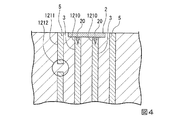
図4は、インペラ翼121の断面図における圧力センサ2周辺の拡大図である。インペラ翼121には、導電部3を外周側から囲うように円柱状に延びるシールド用孔部1211が形成されており、シールド用孔部1211には、その内部を充填されるように導電性接着剤で形成された導電性シールド部5が形成されている。また、インペラ翼121は、円柱状のシールド用孔部1211の内側領域と外側領域を接続するための接続部1212を有している。
FIG. 4 is an enlarged view around the
本実施形態におけるインペラ翼121は、光造形により、あらかじめシールド用孔部1211が形成された状態へ一体成形される。このとき、接続部1212が形成されることにより、シールド用孔部1211の内側領域と外側領域が完全には分断されないため、インペラ翼121の一体成形が可能となっている。
また、導電性シールド部5は、光造形によりインペラ翼121が形成された後、シールド用孔部1211に導電性接着材を流し込み、固化させることによって設けられる。
The
The
上記のような流体機器1によれば、導電性シールド部5が、導電部3への外乱としての電磁波の侵入を抑制する。これにより、導電部3におけるノイズの影響を抑制し、圧力センサ2で検出された値をより高い精度で出力することができる。
According to the fluid device 1 as described above, the
また、本実施形態では、導電性シールド部5は、導電用孔部1210を外周側から囲うように円柱状に延びるシールド用孔部1211を充填するように導電性接着剤から形成される。
これにより、導電部3と同様の形成過程により導電性シールド部5を形成することができる。
Moreover, in this embodiment, the
Thereby, the
また、本実施形態では、シールド用孔部1211は、導電部3を外周側から囲うように円柱状に延びることとしたが、これに限定されることはない。
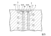
例えば、図5に示すように、シールド用孔部1211は、導電部3を外周側から囲うように螺旋状に延びるように形成されていてもよいし、2つのシールド用孔部が、導電部3を外周側から囲うように二重螺旋状に延びるように形成されてもよい。
またさらに、導電用孔部1210とシールド用孔部1211とを同軸に捩じれる螺旋状としてもよい、即ち、導電量孔部1210とシールド用孔部1211とのツイストペアとして形成してもよい。
In the present embodiment, the
For example, as shown in FIG. 5, the
Furthermore, the
次に、本発明に係る流体機器の第3実施形態について図6と図7を参照して説明する。尚、本実施形態では、上述した第1実施形態との相違点を中心に述べ、同様の部分についてはその説明を省略する。
本実施形態の流体機器1は、インペラ翼121において、導電用孔部1210の内周面と導電部3の外周面の間に電磁遮蔽性シールド部6が設けられている点で第1実施形態と異なる。
Next, a third embodiment of the fluid device according to the present invention will be described with reference to FIGS. In this embodiment, the difference from the first embodiment described above will be mainly described, and the description of the same parts will be omitted.
The fluid device 1 of the present embodiment is the first embodiment in that the
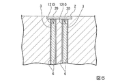
図6は、インペラ翼121の要部拡大図である。導電用孔部1210には、導電部3の外周面に電磁遮蔽材料を含む接着剤で形成された電磁遮蔽性シールド部6が設けられている。ここで、電磁遮蔽材料とは銀、銅、金、アルミニウム等の、電磁波反射損失量や電磁波吸収損失量が比較的大きい物質のことを指す。
FIG. 6 is an enlarged view of a main part of the
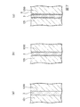
図7は、本実施形態におけるインペラ翼121の製造手順を示す図である。まず、あらかじめ光造形により形成されたインペラ翼121の導電用孔部1210へ、導電性接着剤を流し込む(図7(a))。次に、流しこんだ導電用接着剤を固化させる(図7(b))。このとき、固化に伴い導電性接着剤の体積が減少し、導電用孔部1210には、導電性接着剤で満たされない空隙部分が発生する。最後に、発生した空隙が充填されるように電磁遮蔽材料を含む接着剤を流し込み、固化させる(図7(c))。
FIG. 7 is a diagram showing a manufacturing procedure of the
上記のような流体機器1によれば、第2実施形態同様、電磁遮蔽性シールド部6が導電部3への外乱としての電磁波の侵入を抑制し、導電部3におけるノイズの影響を抑制し、圧力センサ2で検出された値を、より高い精度で出力させることができる。
According to the fluid device 1 as described above, similarly to the second embodiment, the electromagnetic
また、本実施形態では、電磁遮蔽性シールド部6は、導電用孔部1210の内周面と導電部3の外周面の間に形成される。これにより、インペラ翼121に形成する孔部の点数を削減することができる。
Further, in the present embodiment, the
なお、図7に示す手順の他、以下の手順で導電部3、電磁遮蔽性シールド部6を形成してもよい。即ち、まず、電磁遮蔽材料を含む接着剤を導電用孔部1210に流し込む。次いで、導電用孔部1210内にエアを吹き付けることで、該導電用孔部1210の内周面のみに電磁遮蔽材料を含む接着剤が塗布された状態とする。その後、電磁遮蔽材料を含む接着剤を固化させた後に、導電用接着剤を流し込み固化させる。これによっても、上記同様に導電部3、電磁遮蔽性シールド部6を形成することができる。
In addition to the procedure shown in FIG. 7, you may form the
以上、本発明の実施の形態について説明したが、本発明はこれに限定されることなく、その発明の技術的思想を逸脱しない範囲で適宜変更可能である。 The embodiment of the present invention has been described above, but the present invention is not limited to this, and can be appropriately changed without departing from the technical idea of the present invention.
例えば、各実施形態において、流体機器1は、圧力センサ2により作動流体の圧力を検出することとしたが、これに限定されることはない。作動流体の物理量を、電気信号や電気抵抗の変化等、電気的に検出できるセンサであれば何でもよい。
For example, in each embodiment, the fluid device 1 detects the pressure of the working fluid by the
また、第1実施形態において、インペラ翼121は、光造形により形成されるとしたが、これに限定されることはない。例えば、インペラ翼121の基本構造を金属により形成し、さらに導電用孔部1210を機械加工等により形成し、導電用孔部の内周面と導電部3の外周面の間に電気絶縁性の接着剤を流し込み、固化させるようにしてもよい。このように、少なくとも導電部3が電気絶縁性の材料により囲まれていれば、センサが検出した電気信号等を導電部及び導線を介して外部に出力することができる。
In the first embodiment, the
さらに、実施形態ではインペラ翼121に本発明を適用した例について説明したが、例えば案内羽根14に本発明を適用してもよいし、他の部分に本発明を適用してもよい。
なお、インペラ翼121に本発明を適用した場合には、該インペラ翼121自体が回転体のため、スリップリングやテレメータを介して信号を取り出す必要がある。案内羽根14等の静止体に本発明を適用した場合にはその必要がない。
Further, in the embodiment, the example in which the present invention is applied to the
In addition, when the present invention is applied to the
また、各実施形態において、複数の導電部3は、それぞれ異なる色彩の導電性接着剤から形成されていてもよい。これにより、信号線としての導電部3の識別性が向上し、導電部3と導線4の接続作業におけるミスを抑制することができる。
Moreover, in each embodiment, the some
なお、圧力センサ2によって測定をするに際しては、予め校正を行って圧力センサ2の精度を担保しておくことが好ましい。
When measuring with the
さらに、本発明は流体機器であるならば実施形態以外のものにも適用可能であり、例えばポンプ、圧縮機、風力機械(送風機)、タービン、これらの試験機器のようなあらゆる流体機器に適用可能である。 Further, the present invention can be applied to other fluid devices as long as it is a fluid device, and can be applied to all fluid devices such as pumps, compressors, wind machines (blowers), turbines, and these test devices. It is.
1 流体機器
2 圧力センサ
3 導電部
4 導線
5 導電性シールド部
6 電磁遮蔽性シールド部
10 ケーシング
11 主軸
12 インペラ
13 ディフューザハブ
14 案内羽根
15 ベルマウス
20 端子
120 インペラハブ
121 インペラ翼(機器本体)
1210 導電用孔部
1211 シールド用孔部
1212 接続部
DESCRIPTION OF SYMBOLS 1
1210
Claims (9)
前記導電用孔部内を充填するように設けられて、流動性を有する電気伝導材料を固化することで形成された導電部と、
前記導電部に第一面側から接続され、前記作動流体の物理量を検出するセンサと、
前記導電部に第二面側から接続された導線と、を備える流体機器。 A conductive hole is formed in which the first end opens on the first surface in contact with the working fluid and the second end opposite to the first end opens on a second surface different from the first surface. A device body formed of an insulating material;
A conductive portion provided by filling the conductive hole, and formed by solidifying a fluid conductive material;
A sensor connected to the conductive portion from the first surface side and detecting a physical quantity of the working fluid;
A fluid device comprising: a conductive wire connected to the conductive portion from the second surface side.
前記シールド部は、前記シールド用孔部を充填するように設けられた流動性を有する電気伝導材料を固化することで形成される請求項3に記載の流体機器。 A shield hole extending so as to surround the conductive hole from the outer peripheral side of the conductive hole is formed in the device body,
The fluid device according to claim 3, wherein the shield portion is formed by solidifying a fluid conductive material provided so as to fill the shield hole.
前記導電部は、これら複数の導電用孔部のそれぞれに設けられており、前記導電用孔部毎に互いに異なる色彩である請求項1から6のいずれか一項に記載の流体機器。 A plurality of the conductive holes are formed in the device body,
The fluid device according to any one of claims 1 to 6, wherein the conductive portion is provided in each of the plurality of conductive holes and has a different color for each conductive hole.
前記孔部内に、流動性を有する電気伝導材料を充填して該電気伝導材料を固化させることで導電部を形成するステップと、を備える流体機器の製造方法。 A device body in which a first end opens on a first surface in contact with the working fluid and a second end opposite to the first end has a hole opening on a second surface different from the first surface Forming from an electrically insulating material;
Filling the hole with an electrically conductive material having fluidity and solidifying the electrically conductive material to form a conductive part.
前記導電部に、第二面側から導線を接続するステップと、を備える請求項7記載の流体機器の製造方法。 Attaching a sensor for detecting a physical quantity of the working fluid to the first surface;
The method for manufacturing a fluid device according to claim 7, further comprising: connecting a conductive wire to the conductive portion from the second surface side.
Priority Applications (1)
| Application Number | Priority Date | Filing Date | Title |
|---|---|---|---|
| JP2013257251A JP2015114236A (en) | 2013-12-12 | 2013-12-12 | Fluid machinery and method of manufacturing the same |
Applications Claiming Priority (1)
| Application Number | Priority Date | Filing Date | Title |
|---|---|---|---|
| JP2013257251A JP2015114236A (en) | 2013-12-12 | 2013-12-12 | Fluid machinery and method of manufacturing the same |
Publications (1)
| Publication Number | Publication Date |
|---|---|
| JP2015114236A true JP2015114236A (en) | 2015-06-22 |
Family
ID=53528156
Family Applications (1)
| Application Number | Title | Priority Date | Filing Date |
|---|---|---|---|
| JP2013257251A Pending JP2015114236A (en) | 2013-12-12 | 2013-12-12 | Fluid machinery and method of manufacturing the same |
Country Status (1)
| Country | Link |
|---|---|
| JP (1) | JP2015114236A (en) |
Cited By (1)
| Publication number | Priority date | Publication date | Assignee | Title |
|---|---|---|---|---|
| CN119394582A (en) * | 2025-01-02 | 2025-02-07 | 中国空气动力研究与发展中心低速空气动力研究所 | An airfoil structure for high frequency dynamic wind tunnel testing |
-
2013
- 2013-12-12 JP JP2013257251A patent/JP2015114236A/en active Pending
Cited By (1)
| Publication number | Priority date | Publication date | Assignee | Title |
|---|---|---|---|---|
| CN119394582A (en) * | 2025-01-02 | 2025-02-07 | 中国空气动力研究与发展中心低速空气动力研究所 | An airfoil structure for high frequency dynamic wind tunnel testing |
Similar Documents
| Publication | Publication Date | Title |
|---|---|---|
| US10046492B2 (en) | Producing method for cable with resin mold | |
| CN106885681A (en) | A kind of monocline hole dynamic pressure probe for measuring rotor outlet subsonics three-dimensional flow field | |
| CN1916584A (en) | Device for detecting damage of a wind energy turbine rotor blade due to a lightning strike | |
| CN106526219A (en) | High-precision double-redundancy rotation direction-recognizable rotation speed sensor | |
| CN106885649A (en) | A kind of dynamic temperature force combination probe for measuring subsonics Two Dimensional Unsteady flow field | |
| JPH02268202A (en) | Approach detector and manufacture thereof | |
| CN106768597A (en) | A kind of cylinder single hole dynamic pressure probe for measuring rotor outlet two-dimensional flow field | |
| CN110579198B (en) | A device and method for monitoring turbine blade tip clearance | |
| JP2015114236A (en) | Fluid machinery and method of manufacturing the same | |
| CN108037307B (en) | Three-redundancy rotating speed measuring device based on magnetoelectric principle | |
| CN202903819U (en) | Fully-shielded coaxial probe assembly | |
| CN205037984U (en) | Line ear type NTC temperature sensor | |
| CN109990806A (en) | A kind of manufacturing process of current vortex sensor | |
| CN106885682A (en) | A kind of cylindrical type diplopore dynamic pressure probe for measuring rotor outlet subsonics three-dimensional flow | |
| CN204988347U (en) | Miniaturized vibration temperature integral type sensor | |
| CN106940240A (en) | A kind of circular cone diplopore dynamic pressure probe for measuring rotor outlet across sound three-dimensional flow | |
| CN104481894A (en) | Centrifugal electric submersible pump downhole torque testing system | |
| CN207280622U (en) | A kind of temperature sensor for magnetic suspension centrifuge | |
| CN102680007A (en) | Temperature and pressure all-in-one sensor for natural gas pipeline pressure maintaining tests | |
| KR20120138541A (en) | Sensor and wiring equipped method for detecting rotor blade of rotary-wing aircraft | |
| CN106950003B (en) | Conical single-hole dynamic pressure probe for measuring rotor outlet transonic three-dimensional flow field | |
| CN207147653U (en) | A kind of motor bearings temperature measurement structure and motor | |
| CN110735806A (en) | stator blade measuring structure | |
| CN105758556A (en) | Apparatus and method for detecting rotor-side dynamic thermal parameter of medium-low-speed motor in real time | |
| CN216308887U (en) | Magnetic angle detector |