JP2015114206A - Ultrasonic inspection device and ultrasonic inspection method - Google Patents
Ultrasonic inspection device and ultrasonic inspection method Download PDFInfo
- Publication number
- JP2015114206A JP2015114206A JP2013256424A JP2013256424A JP2015114206A JP 2015114206 A JP2015114206 A JP 2015114206A JP 2013256424 A JP2013256424 A JP 2013256424A JP 2013256424 A JP2013256424 A JP 2013256424A JP 2015114206 A JP2015114206 A JP 2015114206A
- Authority
- JP
- Japan
- Prior art keywords
- fusion
- region
- ultrasonic
- wave
- allowable
- Prior art date
- Legal status (The legal status is an assumption and is not a legal conclusion. Google has not performed a legal analysis and makes no representation as to the accuracy of the status listed.)
- Pending
Links
- 238000007689 inspection Methods 0.000 title claims abstract description 37
- 238000000034 method Methods 0.000 title claims description 15
- 230000004927 fusion Effects 0.000 claims abstract description 143
- 230000005540 biological transmission Effects 0.000 claims abstract description 52
- 239000000523 sample Substances 0.000 claims abstract description 37
- 230000002093 peripheral effect Effects 0.000 claims abstract description 7
- 230000007423 decrease Effects 0.000 description 6
- 239000002828 fuel tank Substances 0.000 description 3
- 238000002844 melting Methods 0.000 description 3
- 230000008018 melting Effects 0.000 description 3
- 229920003002 synthetic resin Polymers 0.000 description 2
- 239000000057 synthetic resin Substances 0.000 description 2
- 238000010586 diagram Methods 0.000 description 1
- 238000006073 displacement reaction Methods 0.000 description 1
- 230000000694 effects Effects 0.000 description 1
- 239000000446 fuel Substances 0.000 description 1
Images

Landscapes
- Length Measuring Devices Characterised By Use Of Acoustic Means (AREA)
- Investigating Or Analyzing Materials By The Use Of Ultrasonic Waves (AREA)
Abstract
Description
本発明は、超音波検査装置及び超音波検査方法に関するものである。 The present invention relates to an ultrasonic inspection apparatus and an ultrasonic inspection method.
特許文献1には、超音波を用いて検査対象物の傷の延在方向を識別する方法が開示されている。超音波を用いた検査方法は、融着部材の融着面を融着許容領域に融着する場合において、融着面の全体が融着許容領域の範囲内に納まっているかどうかを検査する手段として用いることができる。 Patent Document 1 discloses a method for identifying the extending direction of a scratch on an inspection object using ultrasonic waves. The inspection method using ultrasonic waves is a means for inspecting whether or not the entire fusion surface is within the range of the fusion allowable region when the fusion surface of the fusion member is fused to the fusion allowable region. Can be used as
上記の検査方法では、超音波プローブを融着許容領域の全領域に亘ってくまなく移動させることにより、融着許容領域における融着面の位置を検出することができるが、融着許容領域が融着面に比べて広い場合には、超音波プローブの移動距離が長くなるため、検査に時間がかかる。
本発明は上記のような事情に基づいて完成されたものであって、検査時間の短縮を図ることを目的とする。
In the above inspection method, the position of the fusion surface in the fusion allowable region can be detected by moving the ultrasonic probe all over the fusion allowable region. If it is wider than the fused surface, the moving distance of the ultrasonic probe becomes longer, and therefore the inspection takes time.
The present invention has been completed based on the above circumstances, and an object thereof is to shorten the inspection time.
第1の発明の超音波検査装置は、
円形の取付面を有する融着部材と、前記取付面との対向面に前記取付面よりも大径の円形をなす融着許容領域が設定された板状部材とを備え、前記融着許容領域に対し、前記取付面のうち中央部を除いた同心円環状の融着領域に点在するように突出形成した複数の融着突起を融着して構成された融着構造を検査対象とし、前記板状部材における前記融着許容領域とは反対側の探査面に配した超音波プローブによって、前記融着許容領域と前記融着領域との位置関係を探査する超音波検査装置であって、
前記融着許容領域の直径をDとし、
前記融着領域の外周縁の半径をRとした上で、
前記超音波プローブにおける超音波の送受信領域の直径dをd=4R−Dに設定し、
前記取付面のうち前記融着領域に囲まれた同心円形の領域を、前記融着領域よりも凹んだ形態であり、半径rがr=d−Rに設定された凹面とし、
前記超音波プローブで受信した反射波の形態に基づいて前記融着許容領域と前記融着領域との位置関係を探査するようになっているところに特徴を有する。
The ultrasonic inspection apparatus of the first invention is
A fusion member having a circular attachment surface; and a plate-like member in which a fusion tolerance region that forms a circle having a larger diameter than the attachment surface is set on a surface facing the attachment surface, the fusion acceptance region On the other hand, a fusion structure formed by fusing a plurality of fusion projections protruding and formed so as to be scattered in a concentric annular fusion region excluding the central portion of the mounting surface is an inspection object, An ultrasonic inspection apparatus for exploring a positional relationship between the fusion-allowable region and the fusion region by using an ultrasonic probe disposed on an exploration surface opposite to the fusion-allowable region in the plate-like member,
The diameter of the fusion allowable region is D,
With the radius of the outer peripheral edge of the fusion region as R,
The diameter d of the ultrasonic wave transmission / reception region in the ultrasonic probe is set to d = 4R−D,
A concentric circular region surrounded by the fusion region of the attachment surface is a shape recessed from the fusion region, and a radius r is set to be a concave surface set to r = d−R,
The present invention is characterized in that a positional relationship between the fusion allowable area and the fusion area is searched based on the form of the reflected wave received by the ultrasonic probe.
第2の発明の超音波検査方法は、
円形の取付面を有する融着部材と、前記取付面との対向面に前記取付面よりも大径の円形をなす融着許容領域が設定された板状部材とを備え、前記融着許容領域に対し、前記取付面のうち中央部を除いた同心円環状の融着領域に点在するように突出形成した複数の融着突起を融着して構成された融着構造を検査対象とし、前記板状部材における前記融着許容領域とは反対側の探査面に配した超音波プローブによって、前記融着許容領域と前記融着領域との位置関係を探査する超音波検査方法であって、
前記融着許容領域の直径をDとし、
前記融着領域の外周縁の半径をRとした上で、
前記超音波プローブにおける超音波の送受信領域の直径dをd=4R−Dに設定し、
前記取付面のうち前記融着領域に囲まれた同心円形の領域を、前記融着領域よりも凹んだ形態であり、半径rがr=d−Rに設定された凹面とし、
前記超音波プローブで受信した反射波の形態に基づいて前記融着許容領域と前記融着領域との位置関係を探査するところに特徴を有する。
The ultrasonic inspection method of the second invention comprises:
A fusion member having a circular attachment surface; and a plate-like member in which a fusion tolerance region that forms a circle having a larger diameter than the attachment surface is set on a surface facing the attachment surface, the fusion acceptance region On the other hand, a fusion structure formed by fusing a plurality of fusion projections protruding and formed so as to be scattered in a concentric annular fusion region excluding the central portion of the mounting surface is an inspection object, An ultrasonic inspection method for exploring a positional relationship between the fusion-acceptable region and the fusion region with an ultrasonic probe disposed on an exploration surface opposite to the fusion-acceptable region in a plate-shaped member,
The diameter of the fusion allowable region is D,
With the radius of the outer peripheral edge of the fusion region as R,
The diameter d of the ultrasonic wave transmission / reception region in the ultrasonic probe is set to d = 4R−D,
A concentric circular region surrounded by the fusion region of the attachment surface is a shape recessed from the fusion region, and a radius r is set to be a concave surface set to r = d−R,
It is characterized in that the positional relationship between the fusion-acceptable region and the fusion region is searched based on the form of the reflected wave received by the ultrasonic probe.
この構成によれば、超音波プローブを移動させることなく、融着許容領域と融着領域との位置関係を探査できるので、融着許容領域の全領域に亘って超音波プローブを移動させる検査装置及び方法に比べると、検査時間を大幅に短縮することができる。 According to this configuration, since the positional relationship between the fusion allowable region and the fusion region can be searched without moving the ultrasonic probe, the inspection apparatus moves the ultrasonic probe over the entire region of the fusion allowable region. Compared with the method, the inspection time can be greatly shortened.
<実施例1>
以下、本発明を具体化した実施例1を図1〜図6を参照して説明する。本実施例の超音波検査装置及び方法は、燃料タンク10を構成する合成樹脂製のタンク本体部11(請求項に記載の板状部材)の内面12(請求項に記載の対向面)と、燃料タンク10内における燃料の波立ちを抑制するための合成樹脂製の消波部材20(請求項に記載の融着部材)の取付面22との融着構造を検査の対象とするものである。
<Example 1>
A first embodiment of the present invention will be described below with reference to FIGS. The ultrasonic inspection apparatus and method according to the present embodiment includes an inner surface 12 (a facing surface according to the claims) of a tank body 11 (a plate member according to the claims) made of a synthetic resin that constitutes the
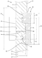
タンク本体部11の内面12(図1,2,4における下面)には、取付面22を取り付けるための円形の融着許容領域13が設定されている。この融着許容領域13は、消波部材20の取付け位置がずれることを見越して、取付面22よりも広い範囲に亘って設定されている。タンク本体部11の内面12のうち融着許容領域13とその周囲の領域は、消波部材20が未溶着の状態で平坦面となっている。また、タンク本体部11の外面のうち融着許容領域13及びその周囲の領域と対応する領域も、平坦面からなる。タンク本体部11のうち融着許容領域13及びその周囲の領域と対応する領域の厚さ寸法は、一定とされている。タンク本体部11の外面のうち融着許容領域13と対応する領域は、探査面14となっている。
On the inner surface 12 (the lower surface in FIGS. 1, 2, and 4) of the tank
消波部材20は、厚さ寸法が一定の基部21を有する。基部21の外面のうちタンク本体部11と対向する領域は、円形の取付面22となっている。取付面22の直径は、融着許容領域13の直径よりも小さい。取付面22は、融着領域23と、凹面26とから構成されている。融着領域23は、取付面22のうちその中央部を除いた領域を構成し、取付面22と同心の円環形をなす。つまり、融着領域23は、取付面22の外周縁に沿って配置されている。したがって、融着領域23の半径と取付面22の半径は同一の寸法となる。
The wave-dissipating
この融着領域23には、円柱状に突出した形態の複数の融着突起24が、一定のピッチ又は規則的な配置で点在するように形成されている。融着領域23のうち融着突起24が形成されていない領域は、平坦状の当接面25となっている。凹面26は、取付面22及び融着領域23と同心の円形をなす。凹面26は、当接面25に対して段差状に凹んだ形態となっている。
In this
検査装置は、超音波Wの発振と、発振した超音波Wの反射波(エコー)の受信とを行う超音波プローブ30と、超音波プローブ30で受信した反射波の強度を表示する表示装置32とを備えている。超音波プローブ30は、平坦面からなる円形の送受信面31(請求項に記載の送受信領域)を有している。この送受信面31の全領域においては、超音波Wが発信されるとともに、その発信した超音波Wの反射波(エコー)を受信するようになっている。表示装置32においては、超音波Wが反射する面までの距離別に、受信した反射波の強度のピーク値が表示される。そして、この反射面までの距離別に検出される反射波のピーク値に基づいて、取付面22の全体が融着許容領域13の範囲内に収まっているか否か(つまり、消波部材20がタンク本体部11の内面12に対して適正な位置関係で融着されているか否か)を判別する。
The inspection apparatus includes an
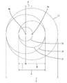
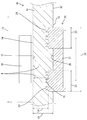
超音波プローブ30は、その送受信面31をタンク本体部11の探査面14に面当たりさせた状態で、融着許容領域13の中央部に同心状に配置される。検査の際には、超音波プローブ30を移動させない。超音波プローブ30を移動させずに検査するための手段として、取付面22が、その中心Xbを融着許容領域13の中心Xaと合致させる同心位置(図1を参照)から、融着許容領域13の範囲内で最も偏心した最大偏心状態(図2,3を参照)において、送受信面31の全体が取付面22と対応し、且つ凹面26の全領域が送受信面31と対応するように、送受信面31の直径寸法dと凹面26の半径寸法rを設定している。
The
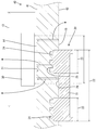
図3に示す最大偏心状態における取付面22の最大ずれ量A(融着許容領域13の中心Xaと取付面22の中心Xbとの距離)は、融着許容領域13の直径Dと融着領域23の半径Rとの関係でいえば、A=(D−2R)/2である。また、融着領域23の半径Rと送受信領域の直径dとの関係でいえば、A=(2R−d)/2である。これにより、d=4R−Dが設定されている。凹面26の半径rについては、図3から明らかなように、r=d−Rに設定される。
The maximum deviation A (the distance between the center Xa of the fusion-
また、図1に示すように、超音波プローブ30の送受信面31(探査面14)から融着領域23の当接面25までの距離をLaとし、送受信面31から凹面26までの距離をLbとし、送受信面31からタンク本体部11の内面12のうち消波部材20と接触しない非接触領域15(つまり、取付面22を包囲する領域)までの距離をLcとすると、その大小関係は、La<Lb<Lcとなっている。尚、非接触領域15は、タンク本体部11の内面12に対する取付面22の取付け位置に応じて変化する。
Further, as shown in FIG. 1, the distance from the transmission / reception surface 31 (search surface 14) of the
次に、本実施例の作用を説明する。消波部材20をタンク本体部11に融着する際には、消波部材20の取付面22をタンク本体部11の内面12に加圧状態で当接させるとともに、その加圧部分を加熱する。すると、融着領域23がタンク本体部11の内面12に食い込み、融着突起24の先端部がタンク本体部11に融着するとともに、当接面25がタンク本体部11の内面12に面当たり状態で当接する。また、凹面26も、タンク本体部11の内面12に対し面当たり状態で当接する。
Next, the operation of this embodiment will be described. When the wave-dissipating
消波部材20をタンク本体部11に融着した際に、図3に示すように、消波部材20の取付面22が融着許容領域13(送受信面31)の中心Xaから径方向に位置ずれしても、その位置ずれ量がR−2/d以内であれば、取付面22の全領域(凹面26の全領域と融着領域23の全体)が融着許容領域13の範囲内に収まり、消波部材20が、タンク本体部11に対して正常な位置関係で融着されていることになる。
When the wave-dissipating
図1〜3に示すように、消波部材20が正常な位置関係で融着された状態では、凹面26の全領域が必ず送受信面31の範囲内に収まる。したがって、取付面22が融着許容領域13内のいずれの位置にあっても、融着領域23の当接面25のうち送受信面31と対応する領域の面積(対応面積)は、ほぼ一定となる。尚、消波部材20が正常な位置関係で融着されている場合、送受信面31に対する当接面25の対応面積は、送受信面31に対する凹面26の対応面積(つまり、凹面26の全面積)よりも小さい。
As shown in FIGS. 1 to 3, when the wave-dissipating
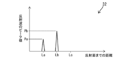
超音波プローブ30の送受信面31から発信された超音波Wは、当接面25と凹面26で反射し、その反射波が送受信面31で受信される。正常に融着された状態では、図5に示すように、表示装置32において、送受信面31から距離Laだけ離れた当接面25(反射面)で反射した反射波のピーク値Paと、送受信面31から距離Lbだけ離れた凹面26(反射面)で反射した反射波のピーク値Pbが表れる。
The ultrasonic wave W transmitted from the transmission /
これらのピーク値Pa,Pbは、送受信面31から反射面までの距離が短いほど大きくなり、反射面の面積が広いほど大きくなる。反射面までの距離に関しては、当接面25までの距離Laが凹面26までの距離Lbより短いのであるが、当接面25における送受信面31との対応面積は、凹面26における送受信面31との対応面積よりも小さい。その結果、当接面25における反射波のピーク値Paは、凹面26における反射波のピーク値Pbよりも小さい。尚、融着突起24の突出端面においては、消波部材20とタンク本体部11とが溶着し、超音波Wは殆ど通過するため、反射波は無視できるほどに弱い。また、非接触領域15は送受信面31と対応していないので、非接触領域15における超音波Wの反射波は発生しない。
These peak values Pa and Pb increase as the distance from the transmission /
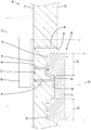
また、図4に示すように、取付面22の一部が融着許容領域13の範囲外にはみ出した不正な状態で消波部材20が融着された場合は、凹面26の一部が送受信面31と非対応となるため、凹面26における送受信面31との対応面積は、正常な融着状態に比べて減少する。また、当接面25における送受信面31との対応面積も、正常な融着状態に比べて減少する。そして、当接面25と凹面26の対応面積の減少分だけ、タンク本体部11の非接触領域15における送受信面31との対応面積が増大する。
In addition, as shown in FIG. 4, when the wave-dissipating
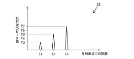
このような不正な融着状態では、超音波プローブ30の送受信面31から発信された超音波Wは、当接面25と凹面26に加え、非接触領域15でも反射し、これらの反射波が送受信面31で受信される。即ち、図6に示すように、表示装置32において、送受信面31から距離Laだけ離れた当接面25(反射面)で反射した反射波のピーク値Pαと、送受信面31から距離Lbだけ離れた凹面26(反射面)で反射した反射波のピーク値Pβの他に、送受信面31から距離Lcだけ離れた非接触領域15(反射面)で反射した反射波のピーク値Pγも表れる。
In such an illegal fusion state, the ultrasonic wave W transmitted from the transmission /
当接面25における反射波のピーク値Pαは、送受信面31との対応面積が減少した分だけ、正常な融着状態のピーク値Paよりも低い。同様に、凹面26における反射波のピーク値Pβも、送受信面31との対応面積が減少した分だけ、正常な融着状態のピーク値Pbよりも低い。そして、融着許容領域13からの取付面22のずれ量が大きくなるほど、ピーク値Pα及びピーク値Pβが小さくなり、逆に、非接触領域15における反射波のピーク値Pγは大きくなる。
The peak value Pα of the reflected wave at the
このように、消波部材20がタンク本体に対して適正な位置関係で融着され、取付面22の全領域が融着許容領域13の範囲内に収まっている状態では、表示装置32に、当接面25における反射波のピーク値Paと凹面26における反射波のピーク値Pbの2つのピーク値のみが表示(図5を参照)される。これに対し、タンク本体に対する消波部材20の融着位置が不適正で、取付面22の一部が融着許容領域13の範囲外へはみ出している状態では、表示装置32に、当接面25における反射波のピーク値Pαと凹面26における反射波のピーク値Pβに加え、非接触領域15における反射波のピーク値Pγを併せた3つのピーク値が表示(図5を参照)される。これにより、タンク本体部11対する消波部材20の融着位置が適正範囲内に収まっているか否かを判別することができる。
Thus, in the state where the wave-dissipating
上述のように、本実施例の超音波検査装置及び方法は、円形の取付面22を有する消波部材20と、取付面22と対向する内面12に取付面22よりも大径の円形をなす融着許容領域13が設定された板状のタンク本体部11とを備え、融着許容領域13に対し、取付面22のうち中央部を除いた同心円環状の融着領域23に点在するように突出形成した複数の融着突起24を融着して構成された融着構造を検査対象とする。そして、タンク本体部11における融着許容領域13とは反対側の探査面14に超音波プローブ30を配し、その超音波プローブ30送受信面31において超音波Wを発信し、その超音波Wの反射波を受信して、その反射波のピーク値の形態に基づいて、融着許容領域13と融着領域23との位置関係を探査する。
As described above, the ultrasonic inspection apparatus and method of this embodiment form a wave-dissipating
検査は、超音波プローブ30を移動させずに行うが、それを実現するために、次のような寸法設定を行っている。融着許容領域13の直径をDとし、融着領域23の外周縁の半径をRとした上で、超音波プローブ30の送受信領域の直径dをd=4R−Dに設定し、取付面22のうち融着領域23に囲まれた同心円形の領域に、融着領域23よりも凹んだ形態であって、半径rがr=d−Rに設定された凹面26を形成した。この構成によれば、超音波プローブ30を移動させることなく、融着許容領域13と融着領域23との位置関係を探査するができるので、融着許容領域13の全領域に亘って超音波プローブ30を移動させる検査装置及び方法に比べると、検査時間を大幅に短縮することができる。
The inspection is performed without moving the
<実施例2>
次に、本発明を具体化した実施例2を図5,7〜9を参照して説明する。本実施例2の超音波検査装置及び検査方法は、燃料タンク40を構成するタンク本体部41(請求項に記載の板状部材)の探査面14(超音波プローブ30の送受信面31)からタンク本体部41の内面42までの距離Lbを、送受信面31から凹面26までの距離Lbと同じ距離に設定したという点に関して、上記実施例1と相違する。その他の構成については上記実施例1と同じであるため、同じ構成については、同一符号を付し、構造、作用及び効果の説明は省略する。
<Example 2>
Next, a second embodiment of the present invention will be described with reference to FIGS. In the ultrasonic inspection apparatus and inspection method of the second embodiment, the tank body 41 (a plate-like member described in the claims) constituting the
消波部材20をタンク本体部41に融着した際に、図7に示すように、消波部材20が正常な位置関係で融着された状態では、実施例1と同様、凹面26の全領域が必ず送受信面31の範囲内に収まる。したがって、表示装置32においては、図5に示すように、送受信面31から距離Laだけ離れた当接面25(反射面)で反射した反射波のピーク値Paと、送受信面31から距離Lbだけ離れた凹面26(反射面)で反射した反射波のピーク値Pbが表れる。そして、当接面25における反射波のピーク値Paは、凹面26における反射波のピーク値Pbよりも小さい。
When the wave-dissipating
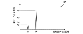
また、図8に示すように、取付面22の一部が融着許容領域13の範囲外にはみ出した不正な状態で消波部材20が融着された場合は、実施例1と同様、超音波プローブ30の送受信面31から発信された超音波Wは、当接面25と凹面26に加え、非接触領域15でも反射し、これらの反射波が送受信面31で受信される。即ち、図9に示すように、表示装置32において、送受信面31から距離Laだけ離れた当接面25(反射面)で反射した反射波のピーク値Pαと、送受信面31から距離Lbだけ離れた凹面26(反射面)及び非接触領域15(反射面)で反射した反射波のピーク値Pδが表れる。
Further, as shown in FIG. 8, when the wave-dissipating
当接面25における反射波のピーク値Pαは、送受信面31との対応面積が減少した分だけ、正常な融着状態のピーク値Paよりも低い。しかし、距離Lbだけ離れた反射面で反射した反射波のピーク値Pδは、正常な融着状態のピーク値Pbよりも大きくなる。
The peak value Pα of the reflected wave at the
何故なら、距離Lbだけ離れた反射面の面積は、凹面26における送受信面31との対応面積と、非接触領域15における送受信面31との対応面積を併せた広さである。換言すると、距離Lbだけ離れた反射面の面積は、送受信面31の面積から、当接面25における送受信面31との対応面積を減じた広さである。不適正な融着状態では、当接面25における送受信面31との対応面積が、正常な融着状態に比べて減少しているので、相対的に、距離Lbだけ離れた反射面の面積は増大していることになる。この面積の増大により、ピーク値Pδは、正常融着時のピーク値Pbよりも大きい値となるのである。
This is because the area of the reflecting surface that is separated by the distance Lb is the combined area of the
本実施例2の検査装置及び方法によれば、消波部材20がタンク本体部41に対して適正な位置関係で融着され、取付面22の全領域が融着許容領域13の範囲内に収まっている状態では、表示装置32に、当接面25における反射波のピーク値Paと、凹面26における反射波のピーク値Pbの2つのピーク値が表示される。一方、タンク本体部41に対する消波部材20の融着位置が不適正で、取付面22の一部が融着許容領域13の範囲外へはみ出している状態でも、表示装置32に、当接面25における反射波のピーク値Pαと、凹面26及び非接触領域15における反射波のピーク値Pδの2つのピーク値が表示される。
According to the inspection apparatus and method of the second embodiment, the wave-dissipating
しかしながら、不適正融着時における距離Laのピーク値Pαが、適正融着時における距離Laのピーク値Paよりも小さいのに対し、不適正融着時における距離Lbのピーク値Pδは、適正融着時における距離Lbのピーク値Pbよりも大きくなる。つまり、適正融着時におけるピーク値Paとピーク値Pbとの差に比べると、不適正融着時におけるピーク値Pαとピーク値Pδとの差が拡大する。したがって、表示装置32に表示される2つのピーク値の差の大小により、消波部材20の融着位置が適正であるか否かを判別することができる。
However, the peak value Pα of the distance La at the time of improper fusion is smaller than the peak value Pa of the distance La at the time of improper fusion, whereas the peak value Pδ of the distance Lb at the time of improper fusion is It becomes larger than the peak value Pb of the distance Lb at the time of wearing. That is, the difference between the peak value Pα and the peak value Pδ at the time of improper fusion is larger than the difference between the peak value Pa and the peak value Pb at the time of proper fusion. Therefore, whether or not the fusion position of the wave-dissipating
<他の実施例>
本発明は上記記述及び図面によって説明した実施例に限定されるものではなく、例えば次のような実施例も本発明の技術的範囲に含まれる。
(1)上記実施例1,2では、タンク本体部の内面が平面である場合について説明したが、タンク本体部の内面は曲面を含んでいてもよい。
(2)上記実施例1,2では、融着領域の当接面が平面である場合について説明したが、当接面は曲面を含んでいてもよい。
(3)上記実施例1,2では、凹面が平面である場合について説明したが、凹面は曲面を含んでいてもよい。
(4)上記実施例1,2では、板状部材をタンク本体部としたが、本発明は、板状部材がタンク本体部以外のものである場合にも適用できる。
(5)上記実施例1,2では、融着部材を消波部材としたが、本発明は、融着部材が消波部材以外のものである場合にも適用できる。
(6)上記実施例1,2では、融着領域の当接面が、タンク本体部の内面に対し食い込んだ状態で面当たりするようにしたが、当接面は、タンク本体部の内面に対し食い込まない状態で当接するようにしてもよい。
(7)上記実施例1,2では、消波部材の融着位置が適正である場合に、当接面における反射波のピーク値が、凹面における反射波のピーク値よりも小さくなるようにしたが、当接面における反射波のピーク値が、凹面における反射波のピーク値より大きくなるようにしてもよい。
<Other embodiments>
The present invention is not limited to the embodiments described with reference to the above description and drawings. For example, the following embodiments are also included in the technical scope of the present invention.
(1) In the first and second embodiments, the case where the inner surface of the tank main body is a flat surface has been described. However, the inner surface of the tank main body may include a curved surface.
(2) In the first and second embodiments, the case where the contact surface of the fusion region is a flat surface has been described. However, the contact surface may include a curved surface.
(3) In the first and second embodiments, the case where the concave surface is a plane has been described. However, the concave surface may include a curved surface.
(4) In the first and second embodiments, the plate-shaped member is the tank main body, but the present invention can also be applied to the case where the plate-shaped member is other than the tank main body.
(5) In Examples 1 and 2, the fusion member is a wave-dissipating member, but the present invention can also be applied to cases where the fusion member is other than the wave-dissipating member.
(6) In the first and second embodiments, the contact surface of the fusion region is in contact with the inner surface of the tank main body while being in contact with the inner surface of the tank main body. You may make it contact | abut in the state which does not bite into.
(7) In the first and second embodiments, when the fusion position of the wave-dissipating member is appropriate, the peak value of the reflected wave on the contact surface is made smaller than the peak value of the reflected wave on the concave surface. However, the peak value of the reflected wave on the contact surface may be larger than the peak value of the reflected wave on the concave surface.
11…タンク本体部(板状部材)
12…内面(取付面との対向面)
13…融着許容領域
14…探査面
20…消波部材(融着部材)
22…取付面
23…融着領域
24…融着突起
26…凹面
30…超音波プローブ
31…送受信面(送受信領域)
41…タンク本体部(板状部材)
42…内面(取付面との対向面)
W…超音波
11 ... Tank body (plate-like member)
12 ... Inner surface (surface facing the mounting surface)
13 ...
DESCRIPTION OF
41 ... Tank body (plate-like member)
42 ... Inner surface (opposite surface to mounting surface)
W ... Ultrasonic
Claims (2)
前記融着許容領域の直径をDとし、
前記融着領域の外周縁の半径をRとした上で、
前記超音波プローブにおける超音波の送受信領域の直径dをd=4R−Dに設定し、
前記取付面のうち前記融着領域に囲まれた同心円形の領域を、前記融着領域よりも凹んだ形態であり、半径rがr=d−Rに設定された凹面とし、
前記超音波プローブで受信した反射波の形態に基づいて前記融着許容領域と前記融着領域との位置関係を探査するようになっていることを特徴とする超音波検査装置。 A fusion member having a circular attachment surface; and a plate-like member in which a fusion tolerance region that forms a circle having a larger diameter than the attachment surface is set on a surface facing the attachment surface, the fusion acceptance region On the other hand, a fusion structure formed by fusing a plurality of fusion projections protruding and formed so as to be scattered in a concentric annular fusion region excluding the central portion of the mounting surface is an inspection object, An ultrasonic inspection apparatus for exploring a positional relationship between the fusion-allowable region and the fusion region by using an ultrasonic probe disposed on an exploration surface opposite to the fusion-allowable region in the plate-like member,
The diameter of the fusion allowable region is D,
With the radius of the outer peripheral edge of the fusion region as R,
The diameter d of the ultrasonic wave transmission / reception region in the ultrasonic probe is set to d = 4R−D,
A concentric circular region surrounded by the fusion region of the attachment surface is a shape recessed from the fusion region, and a radius r is set to be a concave surface set to r = d−R,
An ultrasonic inspection apparatus characterized in that a positional relationship between the fusion allowable area and the fusion area is searched based on a form of a reflected wave received by the ultrasonic probe.
前記融着許容領域の直径をDとし、
前記融着領域の外周縁の半径をRとした上で、
前記超音波プローブにおける超音波の送受信領域の直径dをd=4R−Dに設定し、
前記取付面のうち前記融着領域に囲まれた同心円形の領域を、前記融着領域よりも凹んだ形態であり、半径rがr=d−Rに設定された凹面とし、
前記超音波プローブで受信した反射波の形態に基づいて前記融着許容領域と前記融着領域との位置関係を探査することを特徴とする超音波検査方法。 A fusion member having a circular attachment surface; and a plate-like member in which a fusion tolerance region that forms a circle having a larger diameter than the attachment surface is set on a surface facing the attachment surface, the fusion acceptance region On the other hand, a fusion structure formed by fusing a plurality of fusion projections protruding and formed so as to be scattered in a concentric annular fusion region excluding the central portion of the mounting surface is an inspection object, An ultrasonic inspection method for exploring a positional relationship between the fusion-acceptable region and the fusion region with an ultrasonic probe disposed on an exploration surface opposite to the fusion-acceptable region in a plate-shaped member,
The diameter of the fusion allowable region is D,
With the radius of the outer peripheral edge of the fusion region as R,
The diameter d of the ultrasonic wave transmission / reception region in the ultrasonic probe is set to d = 4R−D,
A concentric circular region surrounded by the fusion region of the attachment surface is a shape recessed from the fusion region, and a radius r is set to be a concave surface set to r = d−R,
An ultrasonic inspection method, wherein a positional relationship between the fusion-accepting region and the fusion region is searched based on a form of a reflected wave received by the ultrasonic probe.
Priority Applications (1)
| Application Number | Priority Date | Filing Date | Title |
|---|---|---|---|
| JP2013256424A JP2015114206A (en) | 2013-12-11 | 2013-12-11 | Ultrasonic inspection device and ultrasonic inspection method |
Applications Claiming Priority (1)
| Application Number | Priority Date | Filing Date | Title |
|---|---|---|---|
| JP2013256424A JP2015114206A (en) | 2013-12-11 | 2013-12-11 | Ultrasonic inspection device and ultrasonic inspection method |
Publications (1)
| Publication Number | Publication Date |
|---|---|
| JP2015114206A true JP2015114206A (en) | 2015-06-22 |
Family
ID=53528130
Family Applications (1)
| Application Number | Title | Priority Date | Filing Date |
|---|---|---|---|
| JP2013256424A Pending JP2015114206A (en) | 2013-12-11 | 2013-12-11 | Ultrasonic inspection device and ultrasonic inspection method |
Country Status (1)
| Country | Link |
|---|---|
| JP (1) | JP2015114206A (en) |
Cited By (1)
| Publication number | Priority date | Publication date | Assignee | Title |
|---|---|---|---|---|
| US12146862B2 (en) | 2021-10-18 | 2024-11-19 | Hyundai Motor Company | Inspection apparatus for a pressure vessel |
-
2013
- 2013-12-11 JP JP2013256424A patent/JP2015114206A/en active Pending
Cited By (1)
| Publication number | Priority date | Publication date | Assignee | Title |
|---|---|---|---|---|
| US12146862B2 (en) | 2021-10-18 | 2024-11-19 | Hyundai Motor Company | Inspection apparatus for a pressure vessel |
Similar Documents
| Publication | Publication Date | Title |
|---|---|---|
| US9297629B2 (en) | Contour standard having a rotationally symmetrical calibration region, use of the standard and method for calibrating and/or monitoring a contour measuring instrument | |
| CN110402388A (en) | Inspection system, control method, and storage medium | |
| EP2813804B1 (en) | Inside-diameter measurement device | |
| US4022055A (en) | Pulse-echo method and system for testing wall thicknesses | |
| US7889326B2 (en) | Distance measuring apparatus | |
| US10444198B2 (en) | Piping inspection apparatus | |
| US4712428A (en) | Ultrasonic flaw detector probe | |
| US10946481B2 (en) | Laser processing device | |
| JP2015114206A (en) | Ultrasonic inspection device and ultrasonic inspection method | |
| CN110088566A (en) | Method and system for measuring at least one geometric feature of a gauge | |
| JP5971274B2 (en) | Ultrasonic vibrator and manufacturing method thereof | |
| JP5963253B2 (en) | Ultrasonic sensor | |
| US3596504A (en) | Ultrasonic search unit | |
| CN112469960B (en) | Device for determining the diameter and/or outer contour of linear objects | |
| US10921292B2 (en) | Supersonic inspection jig and supersonic inspection method | |
| CN104614447A (en) | Method for exciting single vertical guided wave mode by utilizing laser and optical path system | |
| RU2311610C1 (en) | Electro-optic device for controlling parameters of thread | |
| JP2012185078A (en) | Ultrasonic probe and method for measuring circumferential length of tubular object | |
| JP2015137932A (en) | Ultrasonic inspection device and ultrasonic inspection method | |
| WO2019004341A1 (en) | Ultrasonic thickness measuring device | |
| JP2004132978A (en) | Ultrasonic generator, sound velocity measuring device using ultrasonic generator, sound velocity measuring method, and program | |
| JP6814707B2 (en) | Ultrasonic probe and ultrasonic flaw detector | |
| JPH06281630A (en) | Ultrasonic flaw detection device | |
| JPH08313496A (en) | Ultrasonic probe | |
| JP6481435B2 (en) | Optical device |