JP2015114168A - Inspection method for alcohol gas discharger and gas detection device - Google Patents
Inspection method for alcohol gas discharger and gas detection device Download PDFInfo
- Publication number
- JP2015114168A JP2015114168A JP2013255335A JP2013255335A JP2015114168A JP 2015114168 A JP2015114168 A JP 2015114168A JP 2013255335 A JP2013255335 A JP 2013255335A JP 2013255335 A JP2013255335 A JP 2013255335A JP 2015114168 A JP2015114168 A JP 2015114168A
- Authority
- JP
- Japan
- Prior art keywords
- gas
- alcohol
- alcohol gas
- concentration
- main body
- Prior art date
- Legal status (The legal status is an assumption and is not a legal conclusion. Google has not performed a legal analysis and makes no representation as to the accuracy of the status listed.)
- Granted
Links
Images


Landscapes
- Sampling And Sample Adjustment (AREA)
- Feeding, Discharge, Calcimining, Fusing, And Gas-Generation Devices (AREA)
Abstract
【課題】呼気中アルコール濃度測定等の、低濃度ガス用ガス検出装置の検査に使用できるアルコールガス放出器を提供する。さらに、当該アルコールガス放出器を使用するガス検出装置の検査方法を提供する。【解決手段】アルコールガスを放出するガス放出固形物、該ガス放出固形物を収容する収容部、該収容部に形成されたガス放出口、及び該ガス放出口を密閉する蓋、を有する本体部と、該本体部と着脱可能なように接続されるアルコールガス濃度低減手段と、を備え、該アルコールガス濃度低減手段は、アルコールガス濃度を低減するための空間、及び希釈アルコールガス放出部を有し、押圧により変形して該希釈アルコールガスを、該希釈アルコールガス放出部から放出する容器形態である、ガス検出装置検査用のアルコールガス放出器とする。また、該ガス放出器を使用してガス検出装置を検査する。【選択図】図10An alcohol gas discharger that can be used for inspection of a gas detection device for low concentration gas, such as measurement of alcohol concentration in exhaled breath, is provided. Furthermore, the inspection method of the gas detection apparatus which uses the said alcohol gas discharger is provided. A main body having a gas releasing solid that discharges alcohol gas, a storage that stores the gas releasing solid, a gas discharge port formed in the storage, and a lid that seals the gas discharge. And an alcohol gas concentration reducing means detachably connected to the main body, and the alcohol gas concentration reducing means has a space for reducing the alcohol gas concentration and a diluted alcohol gas discharge portion. Then, an alcohol gas discharger for inspecting the gas detection device, which is in the form of a container that is deformed by pressing and discharges the diluted alcohol gas from the diluted alcohol gas discharge portion, is used. In addition, the gas detector is inspected using the gas discharger. [Selection] Figure 10
Description
本発明は、ガス漏れ警報器や、飲酒を検知する呼気中アルコール濃度測定器等のガス検出装置が正常に作動するか否かを検査するためのアルコールガス放出器、及び該アルコールガス放出器を使用したガス検出装置の検査方法に関する。 The present invention relates to an alcohol gas release device for inspecting whether or not a gas detection device such as a gas leak alarm device or an alcohol concentration measuring device in breath for detecting drinking normally operates, and the alcohol gas release device. The present invention relates to an inspection method for a used gas detection device.
従来、ガス検出装置を検査するためのガス放出器としては、例えば、特許文献1において、ガス放出部に気密性を有する蓋を設けたゴム弾性を有する容器に、ガス徐放性のシリカ系無機高分子体を収容したものが提案されており、既に、これを利用した市販品が販売されている。該シリカ系無機高分子体は、反応性シリケートに低分子有機溶剤とアルコール溶液とを酸の触媒下に反応させ、反応後アルカリ触媒を添加して固化させることにより製造されている。
しかし、このような市販のガス放出器は、シリカ系無機高分子体からガスがほとんど放出され、その機能がほとんど終了した場合、その大きさは元の状態の20〜40容量%程度に縮小されるものの固体のまま残存し、また、ガス放出により該残存固体が硬くなる傾向にあった。従って、ガス放出器の機能終期を目視で観察することができず、本来のガス検出装置の検査を有効に行うことができない状態で使用されるという問題が指摘され、また、ガス放出の持続性も必ずしも満足し得るものではなかった。
Conventionally, as a gas discharger for inspecting a gas detection device, for example, in
However, in such a commercially available gas discharger, when the gas is almost released from the silica-based inorganic polymer and its function is almost finished, the size is reduced to about 20 to 40% by volume of the original state. However, it remained as a solid, and the residual solid tended to become hard due to outgassing. Therefore, it is pointed out that the end of the function of the gas discharger cannot be visually observed, and that it is used in a state where the original gas detection device cannot be effectively inspected. Was not always satisfactory.
このような問題を解決するものとして、特許文献2は、テトラエトキシシラン、及びその2〜5量体等の特定の組成を有するガス放出固形物、並びに特定の形状の容器からなるアルコールガス放出器を開示している。
As a solution to such a problem,
しかし、特許文献2に開示されるアルコールガス放出器では、例えば、呼気中アルコール濃度を測定するガス検出装置を検査するような場合には、その放出するアルコールガス濃度が高すぎて、このような低濃度ガス用ガス検出装置の検査には不適であるという問題を本発明者らは見出した。
そこで、本発明は、当該問題を解決し、特に、低濃度ガス用のガス検出装置の検査に使用できるアルコールガス放出器を提供することを課題とする。さらに、当該アルコールガス放出器を使用するガス検出装置の検査方法を提供することを課題とする。
However, in the alcohol gas discharger disclosed in
Then, this invention solves the said problem, and makes it a subject to provide the alcohol gas discharger which can be used especially for the test | inspection of the gas detection apparatus for low concentration gas. Furthermore, it aims at providing the inspection method of the gas detection apparatus which uses the said alcohol gas discharger.
本発明者らは、上記課題を解決するために鋭意検討を行った結果、特定の構造及び構成を備えたアルコールガス濃度低減手段を有するアルコールガス放出器を開発し、本発明を完成させた。さらに、当該アルコールガス濃度低減手段を有するアルコールガス放出器を使用してガス検出装置を検査する方法の発明についても完成させた。 As a result of intensive studies to solve the above-mentioned problems, the present inventors have developed an alcohol gas discharger having an alcohol gas concentration reducing means having a specific structure and configuration, thereby completing the present invention. Further, the invention of a method for inspecting a gas detection device using an alcohol gas discharger having the alcohol gas concentration reducing means has been completed.
すなわち、本発明によれば、アルコールガスを放出するガス放出固形物、該ガス放出固形物を収容する収容部、該収容部に形成されたガス放出口、及び該ガス放出口を密閉する蓋、を有する本体部と、該本体部と着脱可能なように接続されるアルコールガス濃度低減手段と、を備え、該アルコールガス濃度低減手段は、アルコールガス濃度を低減するための空間、及び希釈アルコールガス放出部を有し、押圧により変形して該希釈アルコールガスを、該希釈アルコールガス放出部から放出する容器形態である、ガス検出装置検査用のアルコールガス放出器が提供される。好ましくは、アルコールガス濃度低減手段が本体部の外部表面をスライド可能なように設置され、使用時に、アルコールガス濃度を低減するための空間が形成されるアルコールガス放出器が提供される。 That is, according to the present invention, a gas releasing solid that discharges alcohol gas, a storage that stores the gas releasing solid, a gas discharge formed in the storage, and a lid that seals the gas discharge, And an alcohol gas concentration reducing means detachably connected to the main body, the alcohol gas concentration reducing means comprising: a space for reducing the alcohol gas concentration; and a diluted alcohol gas There is provided an alcohol gas discharger for inspecting a gas detection device, which has a discharge portion and is in the form of a container that is deformed by pressing and discharges the diluted alcohol gas from the diluted alcohol gas discharge portion. Preferably, an alcohol gas discharger is provided in which the alcohol gas concentration reducing means is installed so as to be slidable on the outer surface of the main body, and a space for reducing the alcohol gas concentration is formed during use.
また、本発明によれば、本体部のガス放出口を密閉する蓋を開け、次に、前記本体部を押圧して前記ガス放出固形物から気化しているアルコールガスを、前記アルコールガス濃度低減手段の前記アルコールガス濃度を低減するための空間に放出させ、つづいて、前記アルコールガス濃度を低減するための空間で前記アルコールガスの濃度を低減して希釈アルコールガスを調製した後、前記アルコールガス濃度低減手段を押圧して該希釈アルコールガスを、前記希釈アルコールガス放出部からガス検出装置のガス検知部に放出させて、該ガス検出装置の作動を確認する、ガス検出装置の検査方法が提供される。 Further, according to the present invention, the lid that seals the gas discharge port of the main body is opened, and then the alcohol gas vaporized from the gas discharge solid by pressing the main body is reduced in the alcohol gas concentration. The alcohol gas is discharged into the space for reducing the alcohol gas concentration of the means, and then the diluted alcohol gas is prepared by reducing the concentration of the alcohol gas in the space for reducing the alcohol gas concentration. Provided is an inspection method for a gas detection device in which the concentration reducing means is pressed to release the diluted alcohol gas from the diluted alcohol gas discharge portion to the gas detection portion of the gas detection device to check the operation of the gas detection device. Is done.
本発明のアルコールガス放出器は、本体部内の空間に気化しているアルコールガスを希釈して、アルコールガス濃度を低減するためのアルコールガス濃度低減手段を備えているので、呼気中アルコール濃度を測定するような低濃度ガス用ガス検出装置の検査に好適に使用することができる。
また、本発明のアルコールガス放出器を使用した、ガス検出装置の検査方法によれば、低濃度ガス用ガス検出装置を故障させることなく、適切にその作動状況を検査することができる。
The alcohol gas discharger according to the present invention includes an alcohol gas concentration reducing means for diluting the alcohol gas vaporized in the space in the main body portion to reduce the alcohol gas concentration. It can use suitably for the test | inspection of the gas detection apparatus for such a low concentration gas.
Moreover, according to the inspection method of the gas detection apparatus using the alcohol gas discharger of the present invention, the operation state can be appropriately inspected without causing the gas detection apparatus for low concentration gas to fail.
以下、本発明を更に詳細に説明する。
本発明のアルコールガス放出器は、特定の容器とアルコールガスを放出するガス放出固形物を備えている、ガス検出装置の作動を検査するためのものである。その主要な構成は、ガス放出固形物を内蔵している図1に示したような本体部と、アルコールガス濃度を低減する、すなわち、該本体部から放出されるアルコールガスを希釈する、アルコールガス濃度低減手段とを備えたものである。
なお、本発明に係るアルコールガス放出器における、「アルコールガス」のアルコールとしては、エタノール、メタノール、及びイソプロパノール等を例示することができる。中でも、主としてエタノールを対象とする。
Hereinafter, the present invention will be described in more detail.
The alcohol gas discharger of the present invention is for inspecting the operation of a gas detection device provided with a specific container and a gas discharge solid material for discharging alcohol gas. The main configuration is that the main body portion as shown in FIG. 1 containing the gas releasing solid and the alcohol gas that reduces the alcohol gas concentration, that is, dilutes the alcohol gas released from the main body portion. And a concentration reducing means.
In addition, ethanol, methanol, isopropanol, etc. can be illustrated as alcohol of "alcohol gas" in the alcohol gas discharge device concerning the present invention. Of these, ethanol is mainly targeted.
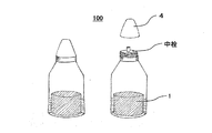
まず、本体部について説明する。図1に示す本体部100は、ガス放出固形物1を内蔵している。好ましくは、本体部100はガス放出固形物を保持する保持部を有している。また、本体部用容器(収容部)2は、ガス放出固形物1から本体部100内の空間に気化しているアルコールガスを、押圧によってガス放出口3から外部に放出でき、押圧力を取り除いた後は、元の形態に戻る弾力を有するものである。なお、使用時以外はガスが外部に漏洩しないようにガス放出口3を密閉する蓋4を有している。
また、ガス放出口3としては、図2(b)に示すような形状であってもよいし、図1(b)に示すような中栓を有する形状であってもよい。アルコールガスを適切にアルコールガス濃度低減手段内に放出させ、空気との混合による希釈がスムーズに行われる点で、図1(b)に示すような中栓を有する形態が好ましい。なお、他の図における本体部においては、簡潔に表現するために中栓を有さない例で示しているが、当然、中栓を有する形態の本体部であってもよい。
First, the main body will be described. A
Further, the
ところで、アルコールガス放出のための押圧は人間の握る力(握力)程度を想定しているので、本体部用容器2は、握力の付与により必要なアルコールガスが放出できる程度に変形し、力を取り除くと元の形態に戻る容器である。例えば、実験用のプラスチック製洗浄瓶に使用される容器のようなものである。さらに、ガス放出固形物の状態を観察できるようにある程度透明であることが好ましい。ガス放出固形物1は、アルコールガスが気化して該固形物1から失われていくにしたがって容量が減少したり、粉状又は顆粒状に崩壊したりするため、外観観察によりその寿命を判断することができるからである。
本体部用容器2の材質としては、ポリプロピレン(PP)、ポリエチレン(PE)、ポリエチレンテレフタレート(PET)、フッ素樹脂、及びエチレン/酢酸ビニル共重合体(EVA)等を例示することができる。
By the way, since the pressure for releasing the alcohol gas is assumed to be about the gripping force of the human (grip strength), the
Examples of the material of the
本発明に使用するアルコールガスを放出するガス放出固形物1は、アルコールガスを徐々に放出するように設計されたものであれば、特に限定されず使用できるが、アルコールガス放出の持続性の点で以下の組成のものが好ましい。すなわち、テトラエトキシシラン、その2〜5量体から選択される少なくとも1種と、エチルアルコールとを、シリカ濃度8.5〜9.5質量%、好ましくは8.8〜9.5質量%となるように混合した混合物100容量部に、少なくとも水40〜55容量部、好ましくは43〜55容量部を混合した後、アルカリ性触媒を添加して固化した固形物、もしくは前記混合物100容量部に、水40〜55容量部、好ましくは43〜55容量部と、着色剤0.5〜1.0質量部及び/又はエチレングリコール1〜5容量部、好ましくは2〜5容量部とを混合した後、アルカリ性触媒を添加して固化した固形物である。
The gas releasing
前記混合物は、例えば、テトラエトキシシランとして市販のエチルシリケートを用いて、上記シリカ濃度となるようにエチルアルコールを混合することにより得ることができる。また、前記アルカリ性触媒としては、例えば、炭酸アンモニウム、水酸化カリウムが挙げられる。 The said mixture can be obtained by mixing ethyl alcohol so that it may become the said silica density | concentration, for example using a commercially available ethyl silicate as tetraethoxysilane. Examples of the alkaline catalyst include ammonium carbonate and potassium hydroxide.
なお、ガス放出固形物1中の残存アルコール量の程度を目視で推測できることが好ましく、そのためには、アルコールガスの放出により、当該固形物1が粉状又は顆粒状に自然崩壊するものが好ましい。粉状又は顆粒状に崩壊したものの量と固形物として残存している量との比較から、残りの寿命がある程度予測可能であるからである。
この自然崩壊作用に好適である点で、アルカリ性触媒としては水酸化カリウムが好ましい。また、同様の理由で、エチレングリコールを上記程度含有させることが好ましい。
さらに、自然崩壊作用の目視での確認がし易い点で、着色剤を上記程度含有させることが好ましい。着色剤としては上記混合物を均質に着色できるものであれば特に限定されないが、その使用目的の点で、原色系のものが好ましい。
In addition, it is preferable that the extent of the residual alcohol amount in the gas discharge | release
Potassium hydroxide is preferred as the alkaline catalyst in that it is suitable for this natural decay action. For the same reason, it is preferable to contain ethylene glycol in the above-mentioned amount.
Furthermore, it is preferable that the colorant is contained in the above-mentioned extent because it is easy to visually confirm the natural decay action. The colorant is not particularly limited as long as it can color the above mixture uniformly, but in terms of its intended purpose, a primary color is preferable.
また、上記ガス放出固形物1の代わりに、日本酒、焼酎あるいはウイスキー等の実際の酒を脱脂綿等に浸漬させたものを、「アルコールガス放出部材」として使用してもよい。 Further, instead of the gas releasing solid 1, a material obtained by immersing actual sake such as sake, shochu or whiskey in absorbent cotton or the like may be used as the “alcohol gas releasing member”.
次に、本発明のアルコールガス放出器の主要特徴部である、アルコールガス濃度低減手段について説明する。該アルコールガス濃度低減手段は、少なくともガス検出装置15の検査時において、アルコールガス濃度を低減するための空間を提供し、本体部100から放出されるアルコールガスを希釈する(アルコールガス濃度を低減する)役割を果たすものである。
また、本体部100と同様に、握力の付与により必要なアルコールガスが放出できる程度に変形し、力を取り除くと元の形態に戻る容器である。そして、容器の材質としては本体部100と同様、ポリプロピレン(PP)、ポリエチレン(PE)、ポリエチレンテレフタレート(PET)、フッ素樹脂、及びエチレン/酢酸ビニル共重合体(EVA)等を例示することができる。
Next, the alcohol gas concentration reducing means, which is the main feature of the alcohol gas discharger of the present invention, will be described. The alcohol gas concentration reducing means provides a space for reducing the alcohol gas concentration at least during the inspection of the
Further, similar to the
アルコールガス濃度低減手段により形成されるアルコールガス濃度を低減するための空間は、本体部100から放出されるアルコールガスの濃度を3〜30倍に希釈できる程度の空間であることが好ましい。
具体的には、本体部用容器2の容積の0.8〜30倍程度が好ましい。本体部用容器2の容積は10〜250mL程度であるので、上記希釈のための空間の容積は8〜300mL程度が好ましい。
The space for reducing the alcohol gas concentration formed by the alcohol gas concentration reducing means is preferably a space that can dilute the concentration of the alcohol gas released from the
Specifically, about 0.8 to 30 times the volume of the
つづいて、本発明のアルコールガス放出器の具体的実施態様及び使用方法について、例を挙げて説明する。 Next, specific embodiments and usage methods of the alcohol gas discharger of the present invention will be described with examples.
実施形態1
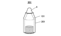
実施形態1の概略を図2に示す。不使用時(保管時)のコンパクト性、及び迅速な使用時形態への変形性の点で好適なように、アルコールガス濃度低減手段201が本体部101の外部表面をスライド可能なように設置されている。すなわち、不使用時には、図2(a)に示すように、アルコールガス濃度低減手段201が本体部101を内包するような配置となり、使用時には図2(b)に示すように、本体部101のガス放出口3の上部にアルコールガス濃度を低減するための空間を形成するような配置となる。
An outline of the first embodiment is shown in FIG. The alcohol gas concentration reducing means 201 is installed so as to be slidable on the outer surface of the
実施形態1のアルコールガス放出器301は、不使用時には図2(a)のようにアルコールガス濃度低減手段201が本体部101の該表面を覆うように、すなわち、本体部101を内包するように設置されている。
ガス検出装置15の検査のための使用時には、まず、本体部101の蓋4を開け、つづいて、アルコールガス濃度低減手段201をスライドさせて図2(b)に示すような配置とする。次に、本体部101を押圧して本体部101の内部空間に気化しているアルコールガスを、アルコールガス濃度低減手段201により形成された空間内に放出し、該空間内でアルコールガスを希釈する。アルコールガス濃度低減手段201により形成された空間は大気と連通しているので、本体部101から放出されたアルコールガスは、空気と混合されてその濃度が低減される。以後、アルコールガス濃度低減手段201により希釈されたアルコールガスを希釈アルコールガスと称する。
The
When the
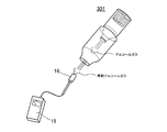
つづいて、アルコールガス濃度低減手段201を押圧し、その希釈アルコールガス放出部5から希釈アルコールガスを、ガス検出装置15のアルコールガスセンサー部16に吹き付けることにより、ガス検出装置15の作動状況を確認、検査する。
Subsequently, the operation state of the
アルコールガス濃度低減手段内でのアルコールガスの希釈を素早く実施するために、アルコールガス濃度低減手段内にガス撹拌手段6を有することが好ましい(例えば、図4の202)。また、アルコールガス濃度低減手段の希釈アルコールガス放出部5にフィルター7を設置することにより、アルコールガス濃度をより低減することができ、低濃度アルコールガスによる検出検査が必要とされるときに好適である。ガス撹拌手段6とフィルター7は、どちらか一方を有するのであっても、両方を有するのであってもよい(実施形態2及び3も同様)。
In order to quickly dilute the alcohol gas in the alcohol gas concentration reducing means, it is preferable to have the gas stirring means 6 in the alcohol gas concentration reducing means (for example, 202 in FIG. 4). Moreover, by installing the
上記ガス撹拌手段6、フィルター7、又はこの両者を有するアルコールガス濃度低減手段の場合は、図3に示すように当該低減手段202が2つに分離できるように構成されることが好ましい。ガス撹拌手段6やフィルター7が図4に示すように配置されるので、本体部101の蓋4を外すためには、ガス撹拌手段6やフィルター7が取り付けられている部分が取り外しできることが必要だからである。
In the case of the alcohol gas concentration reducing means having the gas agitating means 6, the
ガス撹拌手段6の形状例及びアルコールガス濃度低減手段202内での配置例を図4に示す。ガス撹拌手段6の具体例として、紐状又は鎖状の連結部の片末端に重りが接続された形状を挙げることができる。そして、その配置例として、当該連結部の重りが接続されていない他方の末端が、アルコールガス濃度低減手段202の希釈アルコールガス放出部5を形成する容器内表面部に接続される状態を挙げることができる。あるいは、フィルター7が当該放出部5に設置される場合は、該ガス撹拌手段6の他方の末端が該フィルター7に接続される配置であってもよい。
紐状又は鎖状の連結部の材質・形態としては、アルコールガス放出器302を振とうさせたときに、例えば重りが円運動してアルコールガス濃度低減手段202内の気体を撹拌できるような動きができるものであれば特に制限はない。例えば、天然繊維、合成繊維、ゴム若しくはプラスチック(樹脂)製の紐、又はネックレスに使用されるような金属チェーンなどを挙げることができる。
また、重りとしてはその材質に特に制限はなく、樹脂、ゴム、金属、セラミック、木材又は竹材などを挙げることができ、その形状も特に制限はなく、例えば、球形又は多面体形などを挙げることができる。
An example of the shape of the gas stirring means 6 and an arrangement example in the alcohol gas concentration reducing means 202 are shown in FIG. As a specific example of the gas stirring means 6, a shape in which a weight is connected to one end of a string-like or chain-like connecting portion can be mentioned. As an example of the arrangement, the other end to which the weight of the connecting portion is not connected is connected to the inner surface portion of the container forming the diluted alcohol
As the material and form of the string-like or chain-like connecting portion, when the
The weight of the material is not particularly limited, and examples thereof include resin, rubber, metal, ceramic, wood, bamboo, and the like. The shape of the weight is not particularly limited, and examples thereof include a spherical shape and a polyhedral shape. it can.
フィルター7の材質としては、例えば、ポリプロピレン繊維やセルロースを挙げることができるが、握力による押圧及び当該押圧力の開放時に、アルコールガス濃度低減手段202の変形及び回復に支障がなく、また、希釈アルコールガスがフィルター7を通過するときに、周囲の空気も取り込んでさらにアルコール濃度を低減できるものであれば、これらの材質に限られない。具体的には、アサヒ繊維工業株式会社製の「ファイバーロッドシート」などを例示することができる。
Examples of the material of the
実施形態2
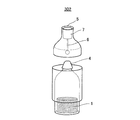
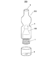
実施形態2の概略を図6に示す。実施形態2のアルコールガス放出器303は、不使用時には、図6(a)に示すように、アルコールガス濃度低減手段203内に本体部100が収納されている。実施形態2のアルコールガス濃度低減手段203は、本体部100の外部表面をスライドする形態ではなく、本体部100を収納するために図7のように2つに分離可能で、その一方には、本体部100のガス放出口3に連結される穴(接続口)8を有し、他方には、希釈アルコールガス放出部5を有している。
実施形態1と同様に、アルコールガス濃度低減手段203はガス撹拌手段6を有することが好ましく、また、フィルター7を希釈アルコールガス放出部5に有することが好ましい(図8)。
An outline of the second embodiment is shown in FIG. When the
As in the first embodiment, the alcohol gas concentration reducing means 203 preferably has the gas stirring means 6 and preferably has the
実施形態2のタイプをガス検出装置15の検査に使用するときは、まず、アルコールガス濃度低減手段203を2つに分離して収納されている本体部100を取り出した後、分離した2つの部材を再度接続してアルコールガス濃度低減手段203とする。なお、この接続部としては、嵌め込み式、ねじ式等を例示できるが、本体部100の収納と取り出しのために分離と一体化が可能であれば、その形式は特に限定されない。
本体部100を取り出した後、本体部100の蓋4を開けて、本体部100のガス放出口3をアルコールガス濃度低減手段203の接続口8に接続し、本体部100を押圧して本体部100の内部空間に気化しているアルコールガスを、アルコールガス濃度低減手段203により形成された空間内に放出し、該空間内でアルコールガスを希釈する(図6(b))。アルコールガス濃度低減手段203により形成された空間は大気と連通しているので、本体部100から放出されたアルコールガスは、空気と混合されてその濃度が低減される。
つづいて、アルコールガス濃度低減手段203を押圧し、その希釈アルコールガス放出部5から希釈アルコールガスを、ガス検出装置15のアルコールガスセンサー部16に吹き付けることにより、ガス検出装置15の作動状況を確認、検査する。
When the type of the second embodiment is used for the inspection of the
After removing the
Subsequently, the operation state of the
アルコールガス濃度低減手段内でのアルコールガスの希釈を素早く実施するために、実施の形態1と同様、図8に示すように、アルコールガス濃度低減手段内にガス撹拌手段6を有することが好ましい。また、アルコールガス濃度低減手段の希釈アルコールガス放出部5にフィルター7を設置することにより、アルコールガス濃度をより低減することができ、低濃度アルコールガスによる検出検査が必要とされるときに好適である。
実施形態2においても、好ましいガス撹拌手段6及びフィルター7は、実施形態1で説明したものと同様である。
In order to quickly dilute the alcohol gas in the alcohol gas concentration reducing means, it is preferable to have a gas stirring means 6 in the alcohol gas concentration reducing means as shown in FIG. Moreover, by installing the
Also in the second embodiment, the preferred gas stirring means 6 and the
実施形態3
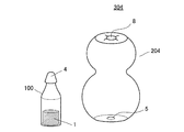
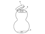
実施形態3の概略を図9に示す。実施形態3のアルコールガス放出器304は、不使用時には、図9(a)に示すように、本体部100とアルコールガス濃度低減手段204とが分離されているものである。アルコールガス濃度低減手段204の希釈アルコールガス放出部5の反対側に、本体部100を接続するための接続口8を有する。また、図9(c)に例示するように、不使用時には、当該接続口8を覆う接続口用蓋9を有していてもよい。
実施形態1及び2と同様に、ガス撹拌手段6及びフィルター7の一方または両方を有することが好ましい。ガス撹拌手段6及びフィルター7を設置する場合は、図4や図8と同様な配置とすればよい。
An outline of the third embodiment is shown in FIG. When the
Similarly to
実施形態3のタイプをガス検出装置15の検査に使用するときは、まず、本体部100の蓋4を開け、本体部100をアルコールガス濃度低減手段204の接続口8に接続する(図9(b))。なお、アルコールガス濃度低減手段204が接続口8を覆う蓋9を有する場合(図9(c))は、当然ながら当該蓋9を開けてから接続する。
次に、本体部100を押圧して本体部100の内部空間に気化しているアルコールガスを、アルコールガス濃度低減手段204の空間内に放出し、該空間内でアルコールガスを希釈する。アルコールガス濃度低減手段204により形成された空間は大気と連通しているので、本体部100から放出されたアルコールガスは、空気と混合されてその濃度が低減される。
つづいて、アルコールガス濃度低減手段204を押圧し、その希釈アルコールガス放出部5から希釈アルコールガスを、ガス検出装置15のアルコールガスセンサー部16に吹き付けることにより、ガス検出装置15の作動状況を確認、検査する。
When using the type of
Next, the alcohol gas vaporized in the internal space of the
Subsequently, the operation state of the
アルコールガス濃度低減手段内でのアルコールガスの希釈を素早く実施するために、実施の形態1と同様、アルコールガス濃度低減手段内にガス撹拌手段6を有することが好ましい。また、アルコールガス濃度低減手段の希釈アルコールガス放出部5にフィルター7を設置することにより、アルコールガス濃度をより低減することができ、低濃度アルコールガスによる検出検査が必要とされるときに好適である。
実施形態3においても、好ましいガス撹拌手段6及びフィルター7は、実施形態1で説明したものと同様である。
In order to quickly dilute the alcohol gas in the alcohol gas concentration reducing means, it is preferable to have the gas stirring means 6 in the alcohol gas concentration reducing means as in the first embodiment. Moreover, by installing the
Also in the third embodiment, the preferable gas stirring means 6 and the
以下、本発明の上記各実施形態を使用したガス検出装置の検査について、実施例により説明するが、本発明はこれらに限定されない。
1.ガス検出装置
新コスモス電機株式会社製の可燃性ガス検知器:XP−3110(アルコールガス用)を使用した。当該ガス検出装置は、アルコール(エタノール)ガスに対して正常に作動、検知することを事前に確認したものを使用した。
Hereinafter, although an Example demonstrates the test | inspection of the gas detection apparatus using each said embodiment of this invention, this invention is not limited to these.
1. Gas detector New Cosmos Electric Co., Ltd. combustible gas detector: XP-3110 (for alcohol gas) was used. The gas detector used was confirmed in advance to normally operate and detect alcohol (ethanol) gas.
2.ガス放出固形物:
シリカ濃度18質量%の市販のエチルシリケート50mLにエチルアルコール(エタノール)50mLを混合し、シリカ濃度9.0質量%のシリケート溶液を調製した。この溶液に、エチレングリコール3mLと、表1に示す量の水を混合し、更に、水酸化カリウム3mLを加えて室温で固化させ、以下の実施例に使用するガス放出固形物1とした。
以下に説明する各実施例においては、このようにして調製したガス放出固形物1をいずれも約3cm3使用した。
具体的には、上記各原料を調合した固化する前の「ガス放出固形物用調合物」を本体部の収容部2(保持部を有する場合は保持部)に充填し、収容部内で約15分間静置して固化させた。なお、固化時間は調合組成により異なるが、5分間から5時間程度で固化してガス放出固形物1となる。
後述する実施形態1型を使用した実施例では、当該ガス放出固形物1の代わりに、脱脂綿にウイスキー(アルコール度数:37度)約3mLを含浸させたものを本体部に収容したものについても試験した。
2. Outgassing solids:
50 mL of ethyl alcohol (ethanol) was mixed with 50 mL of commercially available ethyl silicate having a silica concentration of 18% by mass to prepare a silicate solution having a silica concentration of 9.0% by mass. To this solution, 3 mL of ethylene glycol and the amount of water shown in Table 1 were mixed, and further 3 mL of potassium hydroxide was added and solidified at room temperature to obtain a gas releasing solid 1 used in the following examples.
In each of the examples described below, about 3 cm 3 of the gas releasing solid 1 prepared in this way was used.
Specifically, the “gas-released solid preparation” before mixing and solidifying the raw materials is filled in the housing portion 2 (holding portion in the case of having a holding portion) of the main body, and about 15 in the housing portion. Allowed to stand and solidify for a minute. In addition, although solidification time changes with preparation compositions, it solidifies in about 5 minutes to 5 hours, and turns into the gas discharge | release
In an example using the first embodiment, which will be described later, instead of the gas releasing solid 1, a test was also conducted on a case in which about 3 mL of whiskey (alcohol: 37 degrees) impregnated with absorbent cotton was contained in the main body. did.
3.本体部の概要(及び保持部):
本体部としては、実施形態1〜3いずれの場合も同じものを使用した。具体的には、ポリプロピレン(PP)製の容量約10mLの容器中に上記ガス放出固形物を収容したものを使用した。その概略図を図1に示す。図1では図示していないが、振動等によってガス放出固形物が本体部内を自在に動かないように、本体部の下部にガス放出固形物の保持部を設け、当該保持部内に上記のようにしてガス放出固形物を保持した。
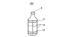
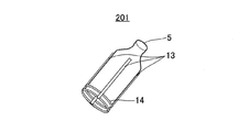
なお、下記実施形態1型の場合の本体部101としては、図5(a)に示すように、その容器外表面において、アルコールガス濃度低減手段201をスライドおよび固定できるように移動用レール10及びストッパー11及び12等が設置されたものを使用した。図5(a)では、内部に収容されているガス放出固形物は省略している。
本体部100(又は101)に握力による押圧力を付加することにより、通常、本体部容量の15〜30%に相当するアルコールガスを含んだ気体(大部分空気)が、ガス放出口3より放出されるものと考えられる。当然ながら、当該放出気体量は押圧力によって変動する。
3. Outline of main unit (and holding unit):
As the main body, the same body was used in any of
In addition, as shown in FIG. 5A, the
By applying a pressing force by gripping force to the main body 100 (or 101), a gas (almost air) containing alcohol gas corresponding to 15 to 30% of the main body capacity is normally discharged from the
4.アルコールガス濃度低減手段
(1)実施形態1型:スライドタイプ
実施形態1型のアルコールガス濃度低減手段201は、ポリプロピレン製の、底部が解放された容器用の形状で、本体部101外表面のアルコールガス濃度低減手段スライド用レール10に嵌め込むレール受け13を有している。また、使用時及び不使用時それぞれにおいて、本体部101外表面に固定するために、アルコールガス濃度低減手段固定用ストッパー11及び12に嵌め込む固定用爪14を有している。その概略図を図5(b)に示す。本アルコールガス濃度低減手段201は、本体部101の外表面をスライドさせるため底部が解放されているが、底部があるとした場合の容量は約25mLのものを使用した。また、本実施例では、撹拌手段及びフィルターを備えていないものを使用した。
アルコールガス濃度低減手段201に握力による押圧力を付加することにより、通常、当該容量の20〜65%に相当するアルコールガスを含んだ気体(大部分空気)が希釈アルコールガス放出部5より放出されるものと考えられる。当然ながら、当該放出気体量は押圧力によって変動する。
実施形態1型のアルコールガス濃度低減手段201を本体部101に設置した状態(アルコールガス放出器の一実施形態)を図2に示す。図2(a)は不使用時(保管時)、図2(b)は使用時(ガス検出装置検査時)の状態を表す。なお、図2においては、アルコールガス濃度低減手段201をスライドさせるためのレール及びレール受け等を省略している。
4). Alcohol gas concentration reducing means (1)
By applying a pressing force by gripping force to the alcohol gas concentration reducing means 201, a gas (almost air) containing alcohol gas corresponding to 20 to 65% of the capacity is normally released from the diluted alcohol
FIG. 2 shows a state in which the first embodiment type alcohol gas concentration reducing means 201 is installed in the main body 101 (one embodiment of the alcohol gas discharger). 2A shows a state when not in use (during storage), and FIG. 2B shows a state when in use (during inspection of the gas detection device). In FIG. 2, rails and rail receivers for sliding the alcohol gas concentration reducing means 201 are omitted.
(2)実施形態2型:本体部内蔵型
実施形態2型のアルコールガス濃度低減手段203は、ポリプロピレン製の容量約40mLの容器用形状で、底部に本体部100のガス放出口3を接続する接続部8を有し、内部に収納する本体部100の出し入れのため2つに分離可能なものを使用した。
また、撹拌手段及びフィルターを備えていないもの(実施例2)、フィルターa(ファイバーロッドシート:ポリプロピレン繊維製、厚さ10mm、アサヒ繊維工業株式会社製)が希釈アルコールガス放出部5に設置されたもの(実施例3)、及びフィルターb(ファイバーロッドシート:ポリプロピレン繊維製、厚さ15mm、アサヒ繊維工業株式会社製)が希釈アルコールガス放出部5に設置されたもの(実施例4)、以上3種類を使用した。
アルコールガス濃度低減手段203に握力による押圧力を付加することにより、通常、当該容量の15〜60%に相当するアルコールガスを含んだ気体(大部分空気)が希釈アルコールガス放出部5より放出されるものと考えられる。当然ながら、当該放出気体量は押圧力によって変動する。
実施形態2型のアルコールガス濃度低減手段203を用いたアルコールガス放出器303の形態例を図6に示す。図6(a)は不使用時(保管時)、図6(b)は使用時(ガス検出装置検査時)の状態を表す。
(2) Second Embodiment Type: Built-in Main Body Type The alcohol gas concentration reducing means 203 of the second embodiment has a shape for a container having a capacity of about 40 mL made of polypropylene, and connects the
In addition, a filter (a fiber rod sheet: made of polypropylene fiber,
By applying a pressing force by gripping force to the alcohol gas concentration reducing means 203, a gas (almost air) containing alcohol gas corresponding to 15 to 60% of the capacity is normally released from the diluted alcohol
An example of the configuration of the
(3)実施形態3型:分離型
実施形態3型のアルコールガス濃度低減手段204は、ポリプロピレン製の容量約55mLの瓢箪型容器用形状で、容器の頭頂部に本体部100のガス放出口3を接続する接続部8を有し、底部に希釈アルコールガス放出部5を有するものを使用した。実施形態3型のアルコールガス濃度低減手段204は、保管時においても本体部100と分離しているので、その容量範囲の自由度が他の2つの型より比較的大きく、所望のアルコールガス濃度低減率に合わせてその容器容量を設計し易いという利点を有する。本実施形態では握力による押圧のし易さの点で瓢箪型を使用したが、瓢箪型である必要はない。
アルコールガス濃度低減手段204に握力による押圧力を付加することにより、通常、当該容量の25〜60%に相当するアルコールガスを含んだ気体(大部分空気)が希釈アルコールガス放出部5より放出されるものと考えられる。当然ながら、当該放出気体量は押圧力によって変動する。
実施形態2型のアルコールガス濃度低減手段204を用いたアルコールガス放出器304の形態例を図9に示す。図9(a)は不使用時(保管時)、図9(b)は使用時(ガス検出装置検査時)の状態を表す。本実施例では、図9(c)に示す蓋付きタイプを使用した。
(3)
By applying a pressing force by gripping force to the alcohol gas concentration reducing means 204, normally, a gas (almost air) containing alcohol gas corresponding to 25 to 60% of the capacity is discharged from the diluted alcohol
An embodiment of an
実施例1:実施形態1型
2.で説明したガス放出固形物1を内蔵した本体部(レール付)101、及びスライドタイプのアルコールガス濃度低減手段201から構成されるアルコールガス放出器301を使用して、1.のガス検出装置15に対する作動検査を行った。当該ガス検出装置15は正常に作動することが確認されているものを使用した(以下同じ)。
まず、アルコールガス濃度低減手段201を本体部101に装着する前に、本体部101から放出されるアルコールガスについて検査した。すなわち、本体部101の蓋4を開け、ガス放出口3をガス検出装置15のアルコールガスセンサー部16から、13mmの位置に配置した後、本体部容器2を握力により押圧して本体部101内に気化しているアルコール(エタノール)ガスをガス放出口3からアルコールガスセンサー部16に放出させ、その濃度を記録した。このときのアルコール(エタノール)濃度は、ガス検出装置15が表示した最大値とした。
なお、本実施例に使用したガス検出装置15は、エタノール濃度を%LEL(爆発下限限界を基準として算出した濃度)で表示するものであったが、それをppm(気体容積基準、すなわちvolppm)濃度に換算して表1に示した。以後の各表も同様である。ここで、エタノールの爆発限界下限濃度は3.3vol%とされているので、この値を基準とした。
また、同じガス放出固形物1を同量内蔵する、同じ形状の本体部101(容量10mL)を5個作製し、その各々について、各5回検査(アルコール濃度測定)した(以下同じ)。結果を表1に示す。表1中のNo.1〜5は、作製した5個の本体部101に便宜上付与した番号である。
Example 1:
First, before attaching the alcohol gas concentration reducing means 201 to the
In addition, although the
In addition, five main body parts 101 (
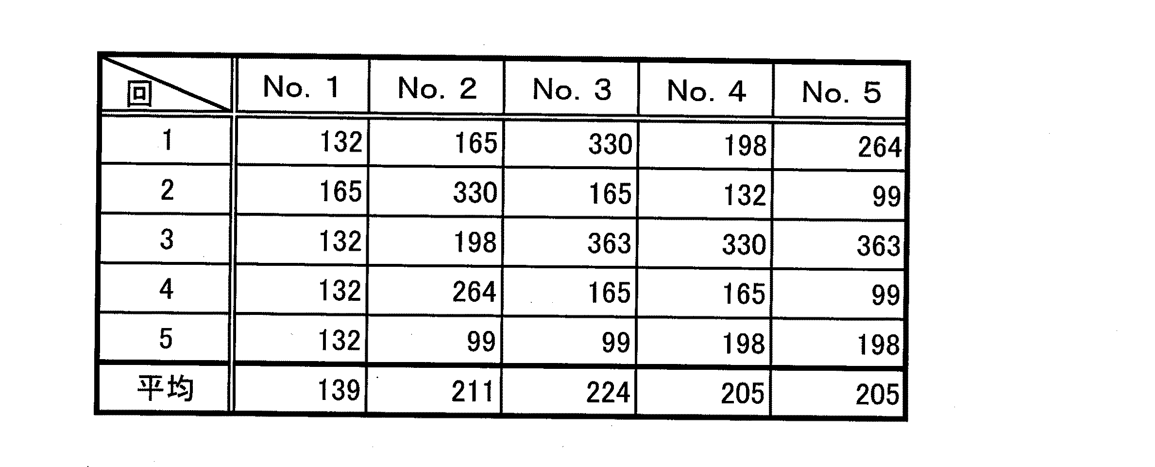
握力による押圧には変動があるため、バラつきはあるものの、いずれも平均1700ppm前後の濃度を示した。例えば、呼気中のアルコール濃度は、「酒気帯び」と判断される濃度が0.15mg/L(上記容積基準のppm濃度に換算すると約73ppm)であるので、本体部から放出されるアルコールガス濃度は、ガス検出装置15の検査としては濃度が高すぎることが判る。
Since there was a variation in the pressing force due to the grip force, all showed a concentration of around 1700 ppm on average, although there was variation. For example, the alcohol concentration in exhalation is 0.15 mg / L (approximately 73 ppm in terms of the above-mentioned volume-based ppm concentration), which is determined to be “alcoholic”, so the concentration of alcohol gas released from the body portion It can be seen that the concentration is too high for the inspection of the
次に、アルコール(エタノール)ガスの希釈、及び希釈アルコールガスによるガス検出装置15の検査について説明する。
(1)まず、スライド式のアルコールガス濃度低減手段201を、上記表1に結果を示した本体部101に取り付け、本体部101のガス放出口3を密封している蓋4を開け、次いで、該アルコールガス濃度低減手段201を本体部101のガス放出口3の上部に移動させた(図2(b))。
(2)次に、本体部101を握力により押圧して本体部101内に気化しているアルコールガスを、アルコールガス濃度低減手段201内に放出させる。つづいて、アルコールガス放出器301全体を手で振ることにより、アルコールガスと空気が混合されて希釈アルコールガスとなる。
(3)アルコールガス濃度低減手段201の希釈アルコールガス放出部5を、ガス検出装置15のアルコールガスセンサー部16から、13mmの位置に配置した後、アルコールガス濃度低減手段201を握力により押圧し、図10に示すように、希釈アルコールガスを希釈アルコールガス放出部5からアルコールガスセンサー部16に放出させ、その濃度を記録した。
(4)このときのアルコール濃度は、ガス検出装置15が表示した最大値とした。
アルコールガス濃度低減手段201についても、同じ形状のもの(容量25mL)を5個作製し、その各々について、各5回検査(アルコール濃度測定)した。結果を表2に示す。表2中のNo.1〜5は、作製した5個のアルコールガス濃度低減手段201に便宜上付与した番号である。また、本実施例では本体部101とアルコールガス濃度低減手段201は同じNo.のものを組み合わせた(以下同じ)。
Next, dilution of alcohol (ethanol) gas and inspection of the
(1) First, the slide type alcohol gas concentration reducing means 201 is attached to the
(2) Next, the alcohol gas vaporized in the
(3) After the diluted alcohol
(4) The alcohol concentration at this time was the maximum value displayed by the
As for the alcohol gas concentration reducing means 201, five pieces having the same shape (capacity 25 mL) were prepared, and each of them was inspected five times (alcohol concentration measurement). The results are shown in Table 2. No. in Table 2 1 to 5 are numbers assigned for convenience to the five alcohol gas concentration reducing means 201 produced. In the present embodiment, the
握力による押圧には変動があるため、バラつきはあるものの、いずれも平均300ppm前後の濃度を示した。
表1と表2のアルコールガス濃度の比較から明確なように、アルコールガス濃度低減手段201によってアルコールガス濃度を、約4〜8倍に希釈することができる。
Since there was a variation in the pressing force due to the grip force, all showed a concentration of around 300 ppm on average, although there was variation.
As is clear from the comparison of the alcohol gas concentrations in Tables 1 and 2, the alcohol gas concentration reducing means 201 can dilute the alcohol gas concentration by about 4 to 8 times.
実施例2:実施形態1型
ガス放出固形物1の代わりに、脱脂綿にウイスキーを含浸させたものを使用した以外は、実施例1と同様にして、ガス検出装置15の検査を実施した。
まず、実施例1と同様にして本体部101から放出されるアルコールガスについて検査した。結果を表3に示す。表3中のNo.は実施例1と同じ(本体部の検査について以下同じ)。
Example 2: The
First, the alcohol gas released from the
いずれも平均1300〜2000ppm程度の濃度を示し、実際の酒であるウイスキーの場合でも、本体部101から放出されるアルコールガス濃度は、ガス検出装置15の検査としては濃度が高すぎる。
In any case, the concentration is about 1300 to 2000 ppm on average, and even in the case of whiskey that is actual liquor, the concentration of alcohol gas released from the
続いて、実施例1と同様にしてウイスキー由来のアルコールガスを希釈し、希釈アルコールガスによるガス検出装置15の検査を行った。結果を表4に示す。
Subsequently, whiskey-derived alcohol gas was diluted in the same manner as in Example 1, and the
握力による押圧には変動があるため、バラつきはあるものの、いずれも平均150ppm前後の濃度を示した。
表3と表4のアルコールガス濃度の比較から明確なように、アルコールガス濃度低減手段201によってアルコールガス濃度を、約10〜15倍に希釈することができる。
Since there was a variation in the pressing force due to the grip force, all showed a concentration of around 150 ppm on average, although there was variation.
As is clear from the comparison of the alcohol gas concentrations in Table 3 and Table 4, the alcohol gas concentration can be diluted about 10 to 15 times by the alcohol gas
実施例3:実施形態2型
2.で説明したガス放出固形物1を内蔵した本体部100(レール無し)、及び本体部内蔵型のアルコールガス濃度低減手段203から構成されるアルコールガス放出器303を使用して、1.のガス検出装置15に対する作動検査を行った。
まず、実施例1と同様にして本体部100から放出されるアルコールガスについて検査した。実施形態2型は、本体部100がアルコールガス濃度低減手段203内に収納されているので、図7に示すように、分離部でアルコールガス濃度低減手段203を2つに分離し、収納されている本体部100を取り出した後、実施例1と同様の操作で本体部100から放出されるアルコールガスの濃度を記録した。結果を表5に示す。
Example 3:
First, the alcohol gas released from the
いずれも平均2200ppm前後の濃度を示し、やはり、本体部100から放出されるアルコールガス濃度は、ガス検出装置15の検査としては濃度が高すぎる。
Both of them show an average concentration of around 2200 ppm, and the concentration of alcohol gas released from the
次に、アルコールガスの希釈、及び希釈アルコールガスによるガス検出装置15の検査について説明する。
(1)まず、本体部100のガス放出口3を密封している蓋4を開け、次いで、アルコールガス濃度低減手段203の接続口8に本体部100のガス放出口3を接続する(図6(b))。
(2)次に、本体部100を握力により押圧して本体部100内に気化しているアルコールガスを、アルコールガス濃度低減手段203内に放出させる。つづいて、アルコールガス放出器303全体を手で振ることにより、アルコールガスと空気が混合されて希釈アルコールガスとなる。
(3)アルコールガス濃度低減手段203の希釈アルコールガス放出部5を、ガス検出装置15のアルコールガスセンサー部16から、13mmの位置に配置した後、アルコールガス濃度低減手段203を握力により押圧し、希釈アルコールガスを希釈アルコールガス放出部5からアルコールガスセンサー部16に放出させ、その濃度を記録した。
(4)このときのアルコール濃度は、ガス検出装置15が表示した最大値とした。
実施例3のアルコールガス濃度低減手段203についても、同じ形状のもの(容量40mL)を5個作製し、その各々について、各5回検査(アルコール濃度測定)した。結果を表6に示す。
Next, dilution of alcohol gas and inspection of the
(1) First, the
(2) Next, the alcohol gas vaporized in the
(3) After the diluted alcohol
(4) The alcohol concentration at this time was the maximum value displayed by the
As for the alcohol gas concentration reducing means 203 of Example 3, five pieces having the same shape (capacity 40 mL) were prepared, and each of them was inspected five times (measurement of alcohol concentration). The results are shown in Table 6.
握力による押圧には変動があるため、バラつきはあるものの、いずれも平均300〜500ppm程度の濃度を示した。 Since there was a variation in the pressing force due to the grip force, all showed a concentration of about 300 to 500 ppm on average although there was variation.
実施例4:実施形態2型
希釈アルコールガス放出部5にフィルターaを有するアルコールガス濃度低減手段(図8において撹拌手段6が設置されていないもの)を使用した以外は、実施例3と同様にして、ガス検出装置15の検査を実施した。結果を表7に示す。
Example 4: Example 2 The same manner as in Example 3 except that the alcohol gas concentration reducing means having the filter a (the apparatus without the stirring means 6 in FIG. 8) was used in the diluted alcohol
握力による押圧には変動があるため、バラつきはあるものの、いずれも平均200ppm前後の濃度を示した。 Since there was a variation in the pressure due to the gripping force, all showed a concentration of around 200 ppm on average, although there was variation.
実施例5:実施形態2型
希釈アルコールガス放出部5にフィルターbを有するアルコールガス濃度低減手段(図8において撹拌手段が設置されていないもの)を使用した以外は、実施例3と同様にして、ガス検出装置15の検査を実施した。結果を表8に示す。
Example 5: The same manner as in Example 3 except that an alcohol gas concentration reducing means having a filter b (no stirring means in FIG. 8) was used in the
握力による押圧には変動があるため、バラつきはあるものの、いずれも平均160ppm前後の濃度を示した。 Since there was a variation in the pressing force due to the grip force, all showed a concentration of around 160 ppm on average, although there were variations.
表5と表6のアルコールガス濃度の比較から明確なように、アルコールガス濃度低減手段203によってアルコールガス濃度を、約4〜8倍に希釈することができる。また、表7及び8の結果から、フィルターを有するアルコールガス濃度低減手段により、フィルターを通過させてアルコールガスを放出すると約10〜15倍希釈できることが判った。
As is clear from the comparison of the alcohol gas concentrations in Tables 5 and 6, the alcohol gas concentration can be diluted about 4 to 8 times by the alcohol gas
実施例6:実施形態3型
2.で説明したガス放出固形物1を内蔵した本体部100(レール無し)、及び分離型のアルコールガス濃度低減手段204から構成されるアルコールガス放出器304を使用して、1.のガス検出装置15に対する作動検査を行った。
まず、ガス放出口3をガス検出装置15のアルコールガスセンサー部16から、10mmの位置に配置した以外は実施例1と同様にして、本体部100から放出されるアルコールガスについて検査した。結果を表9に示す。
Example 6:
First, the alcohol gas released from the
いずれも平均5000ppm前後の濃度を示し、やはり、本体部100から放出されるアルコールガス濃度は、ガス検出装置15の検査としては濃度が高すぎる。この場合のみ本体部100から放出されたアルコールガス濃度が他の場合より高いのは、ガス放出口3とガス検出装置15のアルコールガスセンサー部16との距離が短いからである。
Both of them show an average concentration of about 5000 ppm, and the concentration of alcohol gas released from the
次に、アルコールガスの希釈、及び希釈アルコールガスによるガス検出装置15の検査について説明する。
(1)まず、本体部100のガス放出口3を密封している蓋4を開け、次いで、アルコールガス濃度低減手段204の接続口8に本体部100のガス放出口3を接続する(図9(b))。
(2)次に、本体部100を握力により押圧して本体部100内に気化しているアルコールガスを、アルコールガス濃度低減手段204内に放出させる。つづいて、アルコールガス放出器304全体を手で振ることにより、アルコールガスと空気が混合されて希釈アルコールガスとなる。
(3)アルコールガス濃度低減手段204の希釈アルコールガス放出部5を、ガス検出装置15のアルコールガスセンサー部16から、13mmの位置に配置した後、アルコールガス濃度低減手段204を握力により押圧し、希釈アルコールガスを希釈アルコールガス放出部5からアルコールガスセンサー部16に放出させ、その濃度を記録した。
(4)このときのアルコール濃度は、ガス検出装置15が表示した最大値とした。
実施例6のアルコールガス濃度低減手段204についても、同じ形状のもの(容量55mL)を5個作製し、その各々について、各5回検査(アルコール濃度測定)した。結果を表10に示す。
Next, dilution of alcohol gas and inspection of the
(1) First, the
(2) Next, the alcohol gas vaporized in the
(3) After the diluted alcohol
(4) The alcohol concentration at this time was the maximum value displayed by the
Regarding the alcohol gas concentration reducing means 204 of Example 6, five pieces having the same shape (capacity 55 mL) were prepared, and each of them was inspected five times (alcohol concentration measurement). The results are shown in Table 10.
握力による押圧には変動があるため、バラつきはあるものの、いずれも平均270ppm前後の濃度を示した。 Since there was a variation in the pressing force due to the grip force, all showed a concentration of around 270 ppm on average, although there was variation.
表9と表10のアルコールガス濃度の比較から明確なように、アルコールガス濃度低減手段204によってアルコールガス濃度を、約15〜22倍に希釈することができる。
As is clear from the comparison of the alcohol gas concentrations in Table 9 and Table 10, the alcohol gas concentration can be diluted about 15 to 22 times by the alcohol gas
以上実施例1〜6の結果から明らかなように、本発明の実施形態1〜3いずれのアルコールガス濃度低減手段も、本体部から放出されるアルコールガスの濃度を、効果的かつ簡便に数倍から十数倍低濃度に希釈することができる。なお、アルコールガス濃度低減手段にフィルターが設置されることにより、フィルターが設置されない場合よりアルコールガス濃度を低減させることができる。
従って、本発明のアルコールガス放出器は、低濃度ガス用のガス検出装置の検査に使用できる。例えば、呼気中アルコール濃度を測定するような低濃度アルコールガス用ガス検出装置の検査に好適に使用することができる。よって、バス、電車等の運転手の勤務前酒気帯び検査に使用されるガス検出装置の、正常作動確認のための検査等に簡便に使用できる。さらには、自動車に設置する運転前酒気帯び確認装置の、正常作動確認のための検査等にも簡便に使用できる。
As is clear from the results of Examples 1 to 6 above, the alcohol gas concentration reducing means of any one of
Therefore, the alcohol gas discharger of the present invention can be used for inspection of a gas detection device for low concentration gas. For example, it can be suitably used for inspection of a gas detector for low-concentration alcohol gas that measures the alcohol concentration in exhaled breath. Therefore, it can be easily used for inspection for confirming normal operation of a gas detection device used for a pre-working alcoholic test for drivers such as buses and trains. Furthermore, it can be easily used for an inspection for confirming normal operation of a pre-driving device for confirming a dampness installed in an automobile.
1 ガス放出固形物
2 本体部用容器(収容部)
3 ガス放出口
4 蓋
5 希釈アルコールガス放出部
6 ガス撹拌手段
7 フィルター
8 接続口
9 接続口用蓋
10 アルコールガス濃度低減手段スライド用レール
11 アルコールガス濃度低減手段固定用ストッパー(使用時)
12 アルコールガス濃度低減手段固定用ストッパー(不使用時)
13 レール受け
14 固定用爪
15 ガス検出装置
16 アルコールガスセンサー部
100 本体部
101 本体部(実施形態1型:スライドタイプ用)
201 アルコールガス濃度低減手段(実施形態1型:スライドタイプ用)
202 アルコールガス濃度低減手段(実施形態1型:スライドタイプ用、ガス撹拌手
段及びフィルター付き)
203 アルコールガス濃度低減手段(実施形態2型:本体部内蔵型)
204 アルコールガス濃度低減手段(実施形態3型:分離型)
301 アルコールガス放出器(実施形態1型:スライドタイプ用)
302 アルコールガス放出器(実施形態1型:スライドタイプ用、ガス撹拌手段及び
フィルター付き)
303 アルコールガス放出器(実施形態2型:本体部内蔵型)
304 アルコールガス放出器(実施形態3型:分離型)
1 Gas release solid 2 Main body container (container)
3
12 Alcohol gas concentration reduction means fixing stopper (when not in use)
DESCRIPTION OF
201 Alcohol gas concentration reducing means (
202 Alcohol gas concentration reducing means (
With stage and filter)
203 Alcohol gas concentration reduction means (
204 Alcohol gas concentration reduction means (
301 Alcohol gas discharger (
302 Alcohol gas discharger (
(With filter)
303 Alcohol gas discharger (
304 Alcohol gas discharger (
Claims (9)
該本体部と着脱可能なように接続されるアルコールガス濃度低減手段と、を備え、
該アルコールガス濃度低減手段は、アルコールガス濃度を低減するための空間、及び希釈アルコールガス放出部を有し、押圧により変形して該希釈アルコールガスを、該希釈アルコールガス放出部から放出する容器形態である、
ガス検出装置検査用のアルコールガス放出器。 A main body having a gas releasing solid that discharges alcohol gas, a storage that stores the gas releasing solid, a gas discharge port formed in the storage, and a lid that seals the gas discharge;
An alcohol gas concentration reducing means detachably connected to the main body,
The alcohol gas concentration reducing means has a space for reducing the alcohol gas concentration, and a diluted alcohol gas discharge portion, and is a container configuration that is deformed by pressing and discharges the diluted alcohol gas from the diluted alcohol gas discharge portion. Is,
Alcohol gas discharger for gas detector inspection.
請求項1に記載のガス検出装置検査用のアルコールガス放出器。 The alcohol gas concentration reducing means is installed so as to be slidable on the outer surface of the main body, and a space for reducing the alcohol gas concentration is formed during use.
The alcohol gas discharger for gas detector inspection according to claim 1.
請求項1に記載のガス検出装置検査用のアルコールガス放出器。 When not in use, the main body is accommodated in the alcohol gas concentration reducing means.
The alcohol gas discharger for gas detector inspection according to claim 1.
請求項1〜3いずれか一項に記載のガス検出装置検査用のアルコールガス放出器。 The alcohol gas concentration reducing means has a gas stirring means for stirring the alcohol gas therein.
The alcohol gas discharger for gas detector inspection according to any one of claims 1 to 3.
請求項1〜4いずれか一項に記載のガス検出装置検査用のアルコールガス放出器。 A filter through which the diluted alcohol gas passes is installed in the diluted alcohol gas discharge part,
The alcohol gas discharger for gas detector inspection according to any one of claims 1 to 4.
請求項1〜5いずれか一項に記載のガス検出装置検査用のアルコールガス放出器。 Mixture 100 obtained by mixing at least one selected from the group consisting of tetraethoxysilane and 2 to 5 monomers thereof and ethyl alcohol so that the gas releasing solid material has a silica concentration of 8.5 to 9.5% by mass. After mixing 40 to 55 parts by volume of water with the volume part, an alkaline catalyst is added and solidified.
The alcohol gas discharger for gas detector inspection according to any one of claims 1 to 5.
請求項6に記載のガス検出装置検査用のアルコールガス放出器。 Before the gas release solid is added to the alkaline catalyst, 0.5 to 1.0 parts by mass of a colorant and / or 1 to 5 parts by mass of ethylene glycol are further mixed.
The alcohol gas discharger for gas detector inspection according to claim 6.
請求項1〜7いずれか一項に記載のガス検出装置検査用のアルコールガス放出器。 The gas detection device is a breath alcohol concentration meter;
The alcohol gas discharger for gas detector inspection according to any one of claims 1 to 7.
次に、前記本体部を押圧して前記ガス放出固形物から蒸散しているアルコールガスを、前記アルコールガス濃度低減手段の前記アルコールガス濃度を低減するための空間に放出させ、
つづいて、前記アルコールガス濃度を低減するための空間で前記アルコールガスの濃度を低減して希釈アルコールガスを調製した後、
前記アルコールガス濃度低減手段を押圧して該希釈アルコールガスを、前記希釈アルコールガス放出部からガス検出装置のガス検知部に放出させて、該ガス検出装置の作動を確認する、
ガス検出装置の検査方法。 Opening the lid for sealing the gas discharge port of the main body according to any one of claims 1 to 8,
Next, the alcohol gas evaporating from the gas releasing solid by pressing the main body is discharged into a space for reducing the alcohol gas concentration of the alcohol gas concentration reducing means,
Subsequently, after preparing a diluted alcohol gas by reducing the concentration of the alcohol gas in a space for reducing the alcohol gas concentration,
Pressing the alcohol gas concentration reducing means to release the diluted alcohol gas from the diluted alcohol gas discharge unit to the gas detection unit of the gas detection device to confirm the operation of the gas detection device;
Inspection method for gas detector.
Priority Applications (1)
| Application Number | Priority Date | Filing Date | Title |
|---|---|---|---|
| JP2013255335A JP6215680B2 (en) | 2013-12-10 | 2013-12-10 | Inspection method for alcohol gas discharger and gas detection device |
Applications Claiming Priority (1)
| Application Number | Priority Date | Filing Date | Title |
|---|---|---|---|
| JP2013255335A JP6215680B2 (en) | 2013-12-10 | 2013-12-10 | Inspection method for alcohol gas discharger and gas detection device |
Publications (2)
| Publication Number | Publication Date |
|---|---|
| JP2015114168A true JP2015114168A (en) | 2015-06-22 |
| JP6215680B2 JP6215680B2 (en) | 2017-10-18 |
Family
ID=53528096
Family Applications (1)
| Application Number | Title | Priority Date | Filing Date |
|---|---|---|---|
| JP2013255335A Active JP6215680B2 (en) | 2013-12-10 | 2013-12-10 | Inspection method for alcohol gas discharger and gas detection device |
Country Status (1)
| Country | Link |
|---|---|
| JP (1) | JP6215680B2 (en) |
Citations (6)
| Publication number | Priority date | Publication date | Assignee | Title |
|---|---|---|---|---|
| JPS5269983U (en) * | 1975-11-20 | 1977-05-24 | ||
| JP3001022U (en) * | 1994-02-14 | 1994-08-16 | 新コスモス電機株式会社 | Gas alarm check tool |
| US5731508A (en) * | 1994-09-21 | 1998-03-24 | Dragerwerk Aktiengesellschaft | Calibrating gas generator |
| JP2001050868A (en) * | 1999-08-06 | 2001-02-23 | New Cosmos Electric Corp | Gas supply device and odor identification method |
| JP2010069411A (en) * | 2008-09-18 | 2010-04-02 | Taisei Sangyo Kk | Alcohol gas emitter and vessel |
| US20120125076A1 (en) * | 2007-08-31 | 2012-05-24 | Air Liquide Advanced Technologies Us Llc | Portable metered flow apparatus for calibration/bump testing |
-
2013
- 2013-12-10 JP JP2013255335A patent/JP6215680B2/en active Active
Patent Citations (6)
| Publication number | Priority date | Publication date | Assignee | Title |
|---|---|---|---|---|
| JPS5269983U (en) * | 1975-11-20 | 1977-05-24 | ||
| JP3001022U (en) * | 1994-02-14 | 1994-08-16 | 新コスモス電機株式会社 | Gas alarm check tool |
| US5731508A (en) * | 1994-09-21 | 1998-03-24 | Dragerwerk Aktiengesellschaft | Calibrating gas generator |
| JP2001050868A (en) * | 1999-08-06 | 2001-02-23 | New Cosmos Electric Corp | Gas supply device and odor identification method |
| US20120125076A1 (en) * | 2007-08-31 | 2012-05-24 | Air Liquide Advanced Technologies Us Llc | Portable metered flow apparatus for calibration/bump testing |
| JP2010069411A (en) * | 2008-09-18 | 2010-04-02 | Taisei Sangyo Kk | Alcohol gas emitter and vessel |
Also Published As
| Publication number | Publication date |
|---|---|
| JP6215680B2 (en) | 2017-10-18 |
Similar Documents
| Publication | Publication Date | Title |
|---|---|---|
| US9149774B2 (en) | Selective hydrogen adding equipment for living organism applicable fluid | |
| CN102803156B (en) | Instrument for selective hydrogenation of liquid for biological use | |
| KR101292859B1 (en) | Apparatus for nondestructively producing high-concentration hydrogen solution | |
| KR101165197B1 (en) | Device for selectively hydrogenating biocompatible solution | |
| US9370771B2 (en) | Metal-organic framework extrudates with high packing density and tunable pore volume | |
| US20130098250A1 (en) | Hydrogen adding equipment for living organism applicable fluid | |
| IL192027A0 (en) | Container system for releasably storing a substance | |
| AU2015223925B2 (en) | Fire extinguishing agent discharge apparatus | |
| JPS5819988B2 (en) | Device for detecting free water in hydrocarbon fuels | |
| CN103926240A (en) | Carbon dioxide absorption indicator | |
| JP6215680B2 (en) | Inspection method for alcohol gas discharger and gas detection device | |
| CN102958601B (en) | Deoxidant composition, and deoxidizing packaging material and method for deoxidizing using same | |
| JP5186319B2 (en) | Alcohol gas discharger | |
| JP6275197B2 (en) | Oxygen scavenger and method for producing the same | |
| US20100085201A1 (en) | Function check for a gas-alarm annunciator | |
| JP2017047347A (en) | Method for producing hydrogen water and PET bottle for producing hydrogen water | |
| CN101623582A (en) | Device for indicating and removing formaldehyde | |
| WO2012166760A1 (en) | Test kit for detecting acids in refrigerant lubricating oils and method of use | |
| CA2389211A1 (en) | Material stability test kit | |
| CN101988871B (en) | Device for collecting and measuring expiration | |
| CN201314879Y (en) | Smell testing box | |
| CN213853904U (en) | Permeation device | |
| JP5294161B2 (en) | Moisture resistant oxygen scavenger | |
| JP4942289B2 (en) | Moisture resistant oxygen scavenger | |
| WO2006004004A1 (en) | Method of estimating caking tendency of sodium hydrogen carbonate crystal grain |
Legal Events
| Date | Code | Title | Description |
|---|---|---|---|
| A621 | Written request for application examination |
Free format text: JAPANESE INTERMEDIATE CODE: A621 Effective date: 20161111 |
|
| TRDD | Decision of grant or rejection written | ||
| A01 | Written decision to grant a patent or to grant a registration (utility model) |
Free format text: JAPANESE INTERMEDIATE CODE: A01 Effective date: 20170822 |
|
| A977 | Report on retrieval |
Free format text: JAPANESE INTERMEDIATE CODE: A971007 Effective date: 20170823 |
|
| A61 | First payment of annual fees (during grant procedure) |
Free format text: JAPANESE INTERMEDIATE CODE: A61 Effective date: 20170921 |
|
| R150 | Certificate of patent or registration of utility model |
Ref document number: 6215680 Country of ref document: JP Free format text: JAPANESE INTERMEDIATE CODE: R150 |
|
| R250 | Receipt of annual fees |
Free format text: JAPANESE INTERMEDIATE CODE: R250 |
|
| R250 | Receipt of annual fees |
Free format text: JAPANESE INTERMEDIATE CODE: R250 |