JP2015114152A - System and method for monitoring crossing over of site border at construction site - Google Patents
System and method for monitoring crossing over of site border at construction site Download PDFInfo
- Publication number
- JP2015114152A JP2015114152A JP2013254977A JP2013254977A JP2015114152A JP 2015114152 A JP2015114152 A JP 2015114152A JP 2013254977 A JP2013254977 A JP 2013254977A JP 2013254977 A JP2013254977 A JP 2013254977A JP 2015114152 A JP2015114152 A JP 2015114152A
- Authority
- JP
- Japan
- Prior art keywords
- site
- boundary
- border
- cross
- construction site
- Prior art date
- Legal status (The legal status is an assumption and is not a legal conclusion. Google has not performed a legal analysis and makes no representation as to the accuracy of the status listed.)
- Pending
Links
Images
Landscapes
- Optical Radar Systems And Details Thereof (AREA)
Abstract
Description
本発明は、工事現場の敷地境界の越境監視システム及び方法に関する。 The present invention relates to a cross-border monitoring system and method for a site boundary of a construction site.
住宅敷地への侵入者を監視するシステムとして、敷地境界付近に赤外線センサとカメラとマイクロホンとを設置して、赤外線センサで侵入者を検知し、カメラで敷地境界付近を撮影し、マイクロホンで敷地境界付近の音を録音するものが知られている(例えば、特許文献1参照)。このシステムでは、常時、カメラ及びマイクロホンが作動されて敷地境界付近において撮像・録音が実行されて映像・音声がホームサーバに転送され、赤外線センサにより侵入者が検知されたときに、ホームサーバにおいて映像・音声が録画・録音される。 As a system for monitoring intruders in residential premises, an infrared sensor, camera, and microphone are installed near the site boundary. What records the sound of a neighborhood is known (for example, refer patent document 1). In this system, the camera and microphone are always activated to capture and record in the vicinity of the site boundary, transfer video and audio to the home server, and when an intruder is detected by the infrared sensor,・ Audio is recorded.
ところで、工事現場では、クレーンの吊荷やクレーンのジブが敷地外に出ることや工事現場への入が侵入すること等の敷地境界での越境を監視する必要がある。ここで、工事現場の敷地境界の越境を監視する場合には、人やトラック等の低所での越境からクレーンの吊荷やクレーンのジブ等の高所での越境までを監視する必要がある。そのため、特許文献1に記載のシステムを工事現場の敷地境界の越境を監視するシステムに適用した場合には、低所から高所まで多数の赤外線センサを設置しなければならず、システムが大掛かりになって高コストになる。
By the way, at the construction site, it is necessary to monitor the transboundary at the boundary of the site such as the crane load or the crane jib going out of the site or entering the construction site. Here, when monitoring the crossing of the site boundary of the construction site, it is necessary to monitor the crossing of the border between a low place such as a person or a truck and the crossing of a high place such as a crane load or a crane jib. . Therefore, when the system described in
本発明は、上記事情に鑑み、簡易なシステムにより工事現場の敷地境界の越境の監視を実現することを課題とするものである。 In view of the above circumstances, an object of the present invention is to realize monitoring of the boundary of a site boundary of a construction site with a simple system.
上記課題を解決するために、本発明に係る工事現場の敷地境界の越境監視システムは、工事現場とその隣の敷地との境界である敷地境界において高さ方向に広がるようにレーザ光を走査して走査範囲内に存する物を測距し、測距信号を出力する走査型レーザ測距計と、前記走査型レーザ測距計から出力される前記測距信号の有無に基づいて、前記敷地境界の越境の有無を判定する越境判定部とを備える。 In order to solve the above-described problem, the cross-border monitoring system for a site boundary of a construction site according to the present invention scans a laser beam so as to spread in the height direction at the site boundary that is a boundary between the construction site and the adjacent site. A scanning laser range finder for measuring an object within a scanning range and outputting a ranging signal, and the site boundary based on the presence or absence of the ranging signal output from the scanning laser range finder A cross-border determination unit that determines whether or not there is a cross-border.
前記工事現場の敷地境界の越境監視システムは、前記敷地境界を撮影して映像信号を出力するカメラと、前記カメラから出力された映像信号に基づく映像情報を記憶する記憶部と、前記越境判定部により前記敷地境界の越境が有りと判定された場合に、その判定時点の前後の所定時間内に前記記憶部に記憶された前記映像情報を保存し、前記判定時間の前後の所定時間外に前記記憶部に記憶された前記映像情報を消去する記憶制御部とを備えてもよい。 The cross-border monitoring system for the site boundary of the construction site includes a camera that images the site boundary and outputs a video signal, a storage unit that stores video information based on the video signal output from the camera, and the cross-border determination unit When it is determined that there is a crossing of the site boundary, the video information stored in the storage unit is stored within a predetermined time before and after the determination time, and the video information stored outside the predetermined time before and after the determination time is stored. A storage control unit that erases the video information stored in the storage unit.
前記工事現場の敷地境界の越境監視システムは、前記走査型レーザ測距計から出力された前記測距信号に基づいて前記敷地境界において越境があった位置を算出する位置算出部を備えてもよく、前記記憶部は、前記位置算出部で算出された位置情報を、前記越境判定部により前記敷地境界の越境が有りと判定された時点の前記映像情報と対応付けて記憶してもよい。 The cross-border monitoring system for the site boundary of the construction site may include a position calculation unit that calculates a position where there is a cross-border at the site boundary based on the ranging signal output from the scanning laser range finder. The storage unit may store the position information calculated by the position calculation unit in association with the video information at the time when the crossing boundary determination unit determines that there is a crossing of the site boundary.
また、本発明に係る工事現場の敷地境界の越境監視方法は、走査型レーザ測距計により、工事現場とその隣の敷地との境界である敷地境界において高さ方向に広がるようにレーザ光を走査して走査範囲内に存する物を測距し、前記走査型レーザ測距計により測距される物の有無に基づいて、前記敷地境界の越境の有無を判定する。 In addition, the cross-border monitoring method for the site boundary of the construction site according to the present invention is such that the laser beam is spread by the scanning laser rangefinder so that it spreads in the height direction at the site boundary that is the boundary between the construction site and the adjacent site. An object existing within the scanning range is measured by scanning, and the presence / absence of the boundary of the site boundary is determined based on the presence / absence of the object to be measured by the scanning laser rangefinder.
本発明によれば、簡易なシステムにより工事現場の敷地境界の越境の監視を実現できる。 According to the present invention, it is possible to realize the cross-border monitoring of the site boundary of the construction site with a simple system.
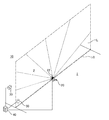
以下、本発明の一実施形態を、図面を参照しながら説明する。図1は、一実施形態に係る工事現場の敷地境界Lの越境監視システム(以下、単に越境監視システムという)10の構成を示す斜視図である。この図に示すように、越境監視システム10は、工事現場1と隣の敷地2との境界(以下、敷地境界という)Lの越境、即ち、クレーンの吊荷やクレーンのジブ、あるいは人やトラック等が、敷地境界Lを超えて工事現場1と隣の敷地2との間で移動することを監視するシステムである。なお、敷地境界Lとは、工事現場1と隣の敷地2との土地の境界線(以下、敷地境界線という)L0から鉛直に立ち上がった面(即ち、敷地境界面)のことをいう。
Hereinafter, an embodiment of the present invention will be described with reference to the drawings. FIG. 1 is a perspective view illustrating a configuration of a cross-border monitoring system 10 (hereinafter simply referred to as a cross-border monitoring system) 10 at a site boundary L of a construction site according to an embodiment. As shown in this figure, the
越境監視システム10は、敷地境界Lに設置されたレーザレンジファインダ(以下、LRFという)20と、敷地境界Lの低所から高所までが画角に入るように敷地境界Lの付近に設置されたWEBカメラ30と、LRF20及びWEBカメラ30が無線又は有線で接続され、LRF20から測距信号が送信され、WEBカメラ30から映像信号が送信されるサーバ40と、回転灯やブザー等の警報装置50とを備えている。ここで、敷地境界Lの低所から高所までとは、敷地境界Lの地面からクレーンの作業高さの最高位までのことをいう。
The
LRF20は、レーザスキャナ、スキャナ式レーザセンサ等とも称される1軸走査型の測域センサであり、レーザ測距計22を回転させることによりレーザ光を走査して走査面内の物体までの距離を測定する。また、レーザ測距計22は、光の伝播時間(Time Of Flight)即ち、光が射出されてから測定対象物で反射されて受光部に戻るまでの時間を測定することにより測距する。なお、LRF20としては、ジック株式会社製のLMS511や、北陽電機株式会社製のUTM−30LX、UTM−30LN等が挙げられる。
The LRF 20 is a single-axis scanning range sensor also called a laser scanner, a scanner-type laser sensor, or the like, and scans a laser beam by rotating the
LRF20は、敷地境界線L0の中央部に設置されており、レーザ測距計22の回転軸22Aは、敷地境界Lに対して直交するように水平に設定されている。ここで、LRF20の走査範囲は、回転軸22Aに対して直交する鉛直線を中心とする180°以上の範囲(例えば、190°)であると共に、LRF20の測定距離が長距離(例えば、80m程度)であることにより、LRF20は、敷地境界Lの全域に亘ってレーザ光を走査できる。
The LRF 20 is installed at the center of the site boundary line L0, and the rotation axis 22A of the
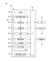
図2は、サーバ40の構成を示すブロック図である。この図に示すように、サーバ40は、LRF20、WEBカメラ30及び警報装置50が無線又は有線で接続され、LRF20から測距信号を受信し、WEBカメラ30から映像信号を受信するインターフェース(以下、I/Fという)41と、I/F41が受信した映像信号や測距信号に基づく映像情報や位置情報を記憶する記憶部42と、記憶部42が記憶した映像情報の保存/消去を選択するCPU43と、敷地境界Lの範囲を設定する設定情報を入力するための設定情報入力部44とを備えている。
FIG. 2 is a block diagram showing the configuration of the
CPU43は、敷地境界Lの範囲を設定する敷地境界設定部431と、LRF20の作動/停止を制御するLRF制御部432と、I/F41が受信した測距信号に基づいて測距対象物の位置を算出する位置算出部433と、I/F41が受信した測距信号の有無、敷地境界認識部431が設定した敷地境界Lの設定情報、及び位置算出部433で算出された位置情報に基づいて敷地境界Lの越境の有無を判定する判定部434と、記憶部42が記憶した映像情報の保存/消去を選択すると共に、位置算出部433が算出した位置情報を記憶部42に記憶させる記憶制御部435と、WEBカメラ30の作動/停止を制御するカメラ制御部436と、警報装置50の作動/停止を制御する警報制御部437とを備えている。
The
設定情報入力部44では、敷地境界Lの範囲を設定する情報、例えば、敷地境界Lの縦横の距離や、敷地境界Lに存する障害物の位置及び範囲等を入力できる。敷地境界設定部431は、設定情報入力部44で入力された敷地境界Lの範囲を設定する情報に基づいて、LRF20による測距範囲を設定する。この際、敷地境界設定部431は、障害物の範囲をLRF20による測距範囲から除く。そして、判定部434は、位置算出部434により算出された被測距物の位置が、敷地境界Lの設定範囲内であるか否かを判定し、設定範囲外である場合には、敷地境界Lの越境が無いものと判定する。
In the setting
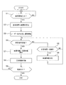
図3は、越境監視システム10の処理を説明するためのフローチャートである。まず、サーバ40の電源が投入されると処理が開始されて、設定情報入力部44で敷地境界Lの範囲を設定する設定情報が入力されると(ステップ1)、敷地境界設定部431が、入力された設定情報に基づいて敷地境界Lの範囲を設定する(ステップ2)。次に、LRF制御部432が、LRF20を作動させて敷地境界Lでのレーザ光の走査を開始させ、カメラ制御部436が、WEBカメラ30を作動させて敷地境界Lの撮影を開始させる(ステップ3)。この際、記憶制御部435は、I/F41がWEBカメラ30から受信した映像信号に基づく映像情報を記憶部42に記憶させる。
FIG. 3 is a flowchart for explaining the processing of the
判定部434は、I/F41が有効な(無効化されない)測距信号を受信したか否かを判定し(ステップ4)、否定判定された場合には、記憶制御部435が、I/F41が測距信号を受信していない時間が所定時間T1(例えば、10秒)継続したか否かを判定し(ステップ5)、ステップ5の否定判定の時点から所定時間T2(<T1、例えば2〜3秒)経過後に、ステップ5の否定判定の時点までに記憶部42に記憶されて保存されていない映像情報を消去する(ステップ6)。I/F41が有効な測距信号を受信していない間は、ステップ4〜6が繰り返し実行される。
The
一方、ステップ4において肯定判定がなされた場合には、記憶制御部437が、肯定判定の時点の所定時間T2前から肯定判定の時点の所定時間T2後までに記憶部42に記憶された映像情報及び位置情報を保存する(ステップ7)。次に、警報制御部437が、警報装置50を作動させる(ステップ8)。そして、サーバ40の電源がONの間はステップ1〜9の処理が繰り返し実行され(ステップ9)、サーバ40の電源がOFFになると処理ルーチンが終了する。
On the other hand, if an affirmative determination is made in step 4, the
以上説明したように、本実施形態に係る越境監視システム10は、敷地境界Lの高さ方向に広がるようにレーザ光を走査して走査範囲内に存する物を測距し、測距信号を出力するLRF20と、LRF20から出力される測距信号の有無に基づいて、敷地境界Lの越境の有無を判定する判定部434とを備える。ここで、LRF20の測距可能な距離は、数十mから百mと長いため、人やトラック等の低所での越境からクレーンの吊荷やクレーンのジブ等の高所での越境までを、1台若しくは数台のLRF20を設置するだけで検出できる。従って、簡易なシステムにより工事現場の敷地境界Lの越境監視を実現できる。
As described above, the
また、本実施形態に係る越境監視システム10は、敷地境界Lを撮影して映像信号を出力するWEBカメラ30と、WEBカメラ30から出力された映像信号に基づく映像情報を記憶する記憶部42と、判定部434により敷地境界Lの越境が有りと判定された場合に、その判定時点の所定時間T2前から判定時点の所定時間T2後までの間に前記記憶部に記憶された映像情報を保存し、判定部434により敷地境界Lの越境が無しと判定されている間に記憶部42に記憶された映像情報を消去する記憶制御部435とを備える。これによって、敷地境界Lを越境した物を記憶部42に記憶された映像により特定できる。例えば、越境をした物が鳥であるかクレーンのジブであるかを区別すること等ができる。また、敷地境界Lの越境が発生していない間に記憶部42に記憶された映像情報を消去することにより、記憶部42における映像情報の保存量を抑えることができ、記憶部42の空き容量の不足を抑えることができる。
The
さらに、本実施形態に係る越境監視システム10は、LRF20から出力された測距信号に基づいて敷地境界Lにおいて越境があった位置を算出する位置算出部433を備え、記憶部42は、位置算出部433で算出された位置情報を、判定部434により敷地境界Lの越境が有りと判定された時点の映像情報と対応付けて記憶する。これによって、敷地境界Lで越境が発生した位置を特定できる。
Furthermore, the
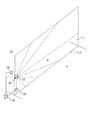
なお、上述の実施形態は、本発明の理解を容易にするためのものであり、本発明を限定するものではない。本発明はその趣旨を逸脱することなく、変更、改良され得ると共に本発明にはその等価物が含まれることは勿論である。例えば、上述の実施形態では、LRF20を、敷地境界線L0の中央に水平軸周りに回転するように設置したが、LRF20の設置方法はこれに限られない。例えば、図4に示すように、LRF20を、敷地境界Lの横方向の一端の中間の高さに設置して、レーザ光を、水平方向を中心に180°以上の範囲で走査させる等してもよい。
In addition, the above-mentioned embodiment is for making an understanding of this invention easy, and does not limit this invention. It goes without saying that the present invention can be changed and improved without departing from the gist thereof, and that the present invention includes equivalents thereof. For example, in the above-described embodiment, the
また、敷地境界Lの付近を撮影するカメラとしてWEBカメラを用いたが、その他のビデオカメラを用いてもよい。また、敷地境界Lの映像を記憶42に保存する時間は適宜設定すればよく、さらに、越境した物の位置を算出して記憶部42に記憶させることは必須ではない。
Further, although the WEB camera is used as a camera for photographing the vicinity of the site boundary L, other video cameras may be used. Further, the time for saving the video of the site boundary L in the
1 工事現場、2 隣の敷地、10 越境監視システム、20 LRF、22 レーザ測距計、30 WEBカメラ、40 サーバ、41 I/F、42 記憶部、43 CPU、44 設定情報入力部、50 警報装置、431 敷地境界設定部、432 LRF制御部、433 位置算出部、434 判定部、435 記憶制御部、436 カメラ制御部、437 警報制御部 1 construction site, 2 adjacent site, 10 cross-border monitoring system, 20 LRF, 22 laser rangefinder, 30 WEB camera, 40 server, 41 I / F, 42 storage unit, 43 CPU, 44 setting information input unit, 50 alarm Device, 431 Site boundary setting unit, 432 LRF control unit, 433 position calculation unit, 434 determination unit, 435 storage control unit, 436 camera control unit, 437 alarm control unit
Claims (4)
前記走査型レーザ測距計から出力される前記測距信号の有無に基づいて、前記敷地境界の越境の有無を判定する越境判定部と
を備える工事現場の敷地境界の越境監視システム。 Scanning laser ranging that scans the laser beam so that it spreads in the height direction at the boundary of the site, which is the boundary between the construction site and the adjacent site, and measures the object existing in the scanning range and outputs a ranging signal Total
A cross-border monitoring system for a site boundary at a construction site, comprising: a cross-border determination unit that determines the presence or absence of a cross-border at the site boundary based on the presence or absence of the ranging signal output from the scanning laser rangefinder.
前記カメラから出力された映像信号に基づく映像情報を記憶する記憶部と、
前記越境判定部により前記敷地境界の越境が有りと判定された場合に、その判定時点の前後の所定時間内に前記記憶部に記憶された前記映像情報を保存し、前記判定時間の前後の所定時間外に前記記憶部に記憶された前記映像情報を消去する記憶制御部と
を備える請求項1に記載の工事現場の敷地境界の越境監視システム。 A camera that images the boundary of the site and outputs a video signal;
A storage unit for storing video information based on a video signal output from the camera;
When it is determined by the cross-border determination unit that there is a crossing of the site boundary, the video information stored in the storage unit is stored within a predetermined time before and after the determination time, and a predetermined value before and after the determination time. A cross-border monitoring system for a site boundary of a construction site according to claim 1, further comprising: a storage control unit that erases the video information stored in the storage unit over time.
前記記憶部は、前記位置算出部で算出された位置情報を、前記越境判定部により前記敷地境界の越境が有りと判定された時点の前記映像情報と対応付けて記憶する請求項2に記載の工事現場の敷地境界の越境監視システム。 A position calculation unit that calculates a position where there is a border crossing at the site boundary based on the distance measurement signal output from the scanning laser rangefinder;
3. The storage unit according to claim 2, wherein the storage unit stores the position information calculated by the position calculation unit in association with the video information at the time when the crossing boundary determination unit determines that there is a crossing of the site boundary. Cross-border monitoring system for construction site boundaries.
前記走査型レーザ測距計により測距される物の有無に基づいて、前記敷地境界の越境の有無を判定する工事現場の敷地境界の越境監視方法。 With a scanning laser range finder, the laser beam is scanned so as to spread in the height direction at the site boundary that is the boundary between the construction site and the adjacent site, and the object existing in the scanning range is measured,
A cross-border monitoring method for a site boundary at a construction site, which determines whether or not there is a cross-border at the site boundary based on the presence or absence of an object to be measured by the scanning laser rangefinder.
Priority Applications (1)
| Application Number | Priority Date | Filing Date | Title |
|---|---|---|---|
| JP2013254977A JP2015114152A (en) | 2013-12-10 | 2013-12-10 | System and method for monitoring crossing over of site border at construction site |
Applications Claiming Priority (1)
| Application Number | Priority Date | Filing Date | Title |
|---|---|---|---|
| JP2013254977A JP2015114152A (en) | 2013-12-10 | 2013-12-10 | System and method for monitoring crossing over of site border at construction site |
Publications (1)
| Publication Number | Publication Date |
|---|---|
| JP2015114152A true JP2015114152A (en) | 2015-06-22 |
Family
ID=53528084
Family Applications (1)
| Application Number | Title | Priority Date | Filing Date |
|---|---|---|---|
| JP2013254977A Pending JP2015114152A (en) | 2013-12-10 | 2013-12-10 | System and method for monitoring crossing over of site border at construction site |
Country Status (1)
| Country | Link |
|---|---|
| JP (1) | JP2015114152A (en) |
Cited By (3)
| Publication number | Priority date | Publication date | Assignee | Title |
|---|---|---|---|---|
| CN106842217A (en) * | 2017-01-16 | 2017-06-13 | 中国人民解放军火箭军工程大学 | A kind of two-way laser radio ranging system for lifting |
| JP2021149795A (en) * | 2020-03-23 | 2021-09-27 | 鹿島建設株式会社 | Crossing over material monitoring system and crossing over material monitoring method |
| JP2023010328A (en) * | 2021-07-09 | 2023-01-20 | エヌ・ティ・ティ・コムウェア株式会社 | Inspection device for equipment construction, inspection method for equipment construction, and inspection program for equipment construction |
Citations (7)
| Publication number | Priority date | Publication date | Assignee | Title |
|---|---|---|---|---|
| JPH01128198A (en) * | 1987-11-13 | 1989-05-19 | Nippon Telegr & Teleph Corp <Ntt> | Automatic monitor method for construction boundary surface |
| JPH09138280A (en) * | 1995-11-14 | 1997-05-27 | Nikon Corp | Monitoring device |
| JPH09204583A (en) * | 1996-01-24 | 1997-08-05 | Nec Corp | Intrusion monitoring device |
| JP2000099862A (en) * | 1998-09-25 | 2000-04-07 | Daiwa House Ind Co Ltd | Intrusion monitoring device for house |
| US20110043806A1 (en) * | 2008-04-17 | 2011-02-24 | Avishay Guetta | Intrusion warning system |
| JP2012198802A (en) * | 2011-03-22 | 2012-10-18 | Denso Corp | Intrusion object detection system |
| JP2013101566A (en) * | 2011-11-09 | 2013-05-23 | Optex Co Ltd | Laser scan sensor |
-
2013
- 2013-12-10 JP JP2013254977A patent/JP2015114152A/en active Pending
Patent Citations (7)
| Publication number | Priority date | Publication date | Assignee | Title |
|---|---|---|---|---|
| JPH01128198A (en) * | 1987-11-13 | 1989-05-19 | Nippon Telegr & Teleph Corp <Ntt> | Automatic monitor method for construction boundary surface |
| JPH09138280A (en) * | 1995-11-14 | 1997-05-27 | Nikon Corp | Monitoring device |
| JPH09204583A (en) * | 1996-01-24 | 1997-08-05 | Nec Corp | Intrusion monitoring device |
| JP2000099862A (en) * | 1998-09-25 | 2000-04-07 | Daiwa House Ind Co Ltd | Intrusion monitoring device for house |
| US20110043806A1 (en) * | 2008-04-17 | 2011-02-24 | Avishay Guetta | Intrusion warning system |
| JP2012198802A (en) * | 2011-03-22 | 2012-10-18 | Denso Corp | Intrusion object detection system |
| JP2013101566A (en) * | 2011-11-09 | 2013-05-23 | Optex Co Ltd | Laser scan sensor |
Cited By (5)
| Publication number | Priority date | Publication date | Assignee | Title |
|---|---|---|---|---|
| CN106842217A (en) * | 2017-01-16 | 2017-06-13 | 中国人民解放军火箭军工程大学 | A kind of two-way laser radio ranging system for lifting |
| CN106842217B (en) * | 2017-01-16 | 2023-06-27 | 中国人民解放军火箭军工程大学 | Bidirectional laser wireless ranging system for hoisting |
| JP2021149795A (en) * | 2020-03-23 | 2021-09-27 | 鹿島建設株式会社 | Crossing over material monitoring system and crossing over material monitoring method |
| JP7508245B2 (en) | 2020-03-23 | 2024-07-01 | 鹿島建設株式会社 | System and method for monitoring cross-border objects |
| JP2023010328A (en) * | 2021-07-09 | 2023-01-20 | エヌ・ティ・ティ・コムウェア株式会社 | Inspection device for equipment construction, inspection method for equipment construction, and inspection program for equipment construction |
Similar Documents
| Publication | Publication Date | Title |
|---|---|---|
| US20220172475A1 (en) | Damage detection and analysis using three-dimensional surface scans | |
| JP6123377B2 (en) | Image processing apparatus, object detection method, and object detection program | |
| KR102230552B1 (en) | Device For Computing Position of Detected Object Using Motion Detect and Radar Sensor | |
| CN103398781A (en) | Temperature detection device for electric equipment | |
| US12236761B2 (en) | Fence monitoring system, fence monitoring apparatus, and fence monitoring method | |
| US20210400240A1 (en) | Image processing apparatus, image processing method, and computer readable medium | |
| CN114758290A (en) | Fire detection method, fire detection device, electronic equipment and storage medium | |
| KR102244501B1 (en) | Guide equipment and inspection device for manhole condition assessment with guide equipment | |
| WO2020166057A1 (en) | Optical fiber sensing system, activity identification device, activity identification method, and computer-readable medium | |
| CN113095142A (en) | Operation monitoring method and system for engineering equipment and engineering equipment | |
| JP3858576B2 (en) | Control method of moving object tracking spotlight control device | |
| JP2015114152A (en) | System and method for monitoring crossing over of site border at construction site | |
| JP6409316B2 (en) | Field recording system | |
| JP6940906B1 (en) | Peripheral monitoring device for work machines | |
| JP6940907B1 (en) | Peripheral monitoring device for work machines | |
| KR101421700B1 (en) | real-time location trace system using intelligent analysis function of cctv and location trace method thereof | |
| KR102927904B1 (en) | Structure investigation support device, structure investigation support method, and program | |
| JP3356278B2 (en) | Collapse detection system | |
| JP2012198802A (en) | Intrusion object detection system | |
| CN105929819B (en) | Method for controlling electronic equipment and electronic equipment | |
| JP7251407B2 (en) | SENSOR INSTALLATION ASSIST DEVICE, SENSOR INSTALLATION ASSIST METHOD AND PROGRAM | |
| JP2014190934A (en) | Tsunami detection system | |
| JP7204356B2 (en) | monitoring device | |
| JP7086752B2 (en) | Monitoring device | |
| JP2018169698A (en) | Position estimation device, position estimation method, and position estimation program |
Legal Events
| Date | Code | Title | Description |
|---|---|---|---|
| A621 | Written request for application examination |
Free format text: JAPANESE INTERMEDIATE CODE: A621 Effective date: 20161118 |
|
| A977 | Report on retrieval |
Free format text: JAPANESE INTERMEDIATE CODE: A971007 Effective date: 20170927 |
|
| A131 | Notification of reasons for refusal |
Free format text: JAPANESE INTERMEDIATE CODE: A131 Effective date: 20171003 |
|
| A521 | Request for written amendment filed |
Free format text: JAPANESE INTERMEDIATE CODE: A523 Effective date: 20171110 |
|
| A131 | Notification of reasons for refusal |
Free format text: JAPANESE INTERMEDIATE CODE: A131 Effective date: 20171219 |
|
| A02 | Decision of refusal |
Free format text: JAPANESE INTERMEDIATE CODE: A02 Effective date: 20180619 |