JP2015114143A - Speed and angle measurement device for moving body - Google Patents
Speed and angle measurement device for moving body Download PDFInfo
- Publication number
- JP2015114143A JP2015114143A JP2013254770A JP2013254770A JP2015114143A JP 2015114143 A JP2015114143 A JP 2015114143A JP 2013254770 A JP2013254770 A JP 2013254770A JP 2013254770 A JP2013254770 A JP 2013254770A JP 2015114143 A JP2015114143 A JP 2015114143A
- Authority
- JP
- Japan
- Prior art keywords
- moving body
- speed
- angle
- antenna
- moving
- Prior art date
- Legal status (The legal status is an assumption and is not a legal conclusion. Google has not performed a legal analysis and makes no representation as to the accuracy of the status listed.)
- Pending
Links
- 238000005259 measurement Methods 0.000 title abstract description 5
- 230000005855 radiation Effects 0.000 claims abstract description 12
- 239000004065 semiconductor Substances 0.000 claims abstract description 7
- 230000007704 transition Effects 0.000 claims abstract description 7
- 230000005540 biological transmission Effects 0.000 claims description 24
- 238000013500 data storage Methods 0.000 claims description 19
- 238000000034 method Methods 0.000 claims description 17
- 238000001514 detection method Methods 0.000 claims description 8
- 238000010586 diagram Methods 0.000 description 4
- 238000011326 mechanical measurement Methods 0.000 description 2
- 238000009826 distribution Methods 0.000 description 1
- 230000005669 field effect Effects 0.000 description 1
- 230000001902 propagating effect Effects 0.000 description 1
- 239000000758 substrate Substances 0.000 description 1
Images


Classifications
-
- G—PHYSICS
- G01—MEASURING; TESTING
- G01S—RADIO DIRECTION-FINDING; RADIO NAVIGATION; DETERMINING DISTANCE OR VELOCITY BY USE OF RADIO WAVES; LOCATING OR PRESENCE-DETECTING BY USE OF THE REFLECTION OR RERADIATION OF RADIO WAVES; ANALOGOUS ARRANGEMENTS USING OTHER WAVES
- G01S13/00—Systems using the reflection or reradiation of radio waves, e.g. radar systems; Analogous systems using reflection or reradiation of waves whose nature or wavelength is irrelevant or unspecified
- G01S13/02—Systems using reflection of radio waves, e.g. primary radar systems; Analogous systems
- G01S13/50—Systems of measurement based on relative movement of target
- G01S13/58—Velocity or trajectory determination systems; Sense-of-movement determination systems
-
- G—PHYSICS
- G01—MEASURING; TESTING
- G01S—RADIO DIRECTION-FINDING; RADIO NAVIGATION; DETERMINING DISTANCE OR VELOCITY BY USE OF RADIO WAVES; LOCATING OR PRESENCE-DETECTING BY USE OF THE REFLECTION OR RERADIATION OF RADIO WAVES; ANALOGOUS ARRANGEMENTS USING OTHER WAVES
- G01S13/00—Systems using the reflection or reradiation of radio waves, e.g. radar systems; Analogous systems using reflection or reradiation of waves whose nature or wavelength is irrelevant or unspecified
- G01S13/02—Systems using reflection of radio waves, e.g. primary radar systems; Analogous systems
- G01S13/06—Systems determining position data of a target
- G01S13/42—Simultaneous measurement of distance and other co-ordinates
- G01S13/424—Stacked beam radar
-
- G—PHYSICS
- G01—MEASURING; TESTING
- G01S—RADIO DIRECTION-FINDING; RADIO NAVIGATION; DETERMINING DISTANCE OR VELOCITY BY USE OF RADIO WAVES; LOCATING OR PRESENCE-DETECTING BY USE OF THE REFLECTION OR RERADIATION OF RADIO WAVES; ANALOGOUS ARRANGEMENTS USING OTHER WAVES
- G01S7/00—Details of systems according to groups G01S13/00, G01S15/00, G01S17/00
- G01S7/02—Details of systems according to groups G01S13/00, G01S15/00, G01S17/00 of systems according to group G01S13/00
- G01S7/03—Details of HF subsystems specially adapted therefor, e.g. common to transmitter and receiver
- G01S7/034—Duplexers
Landscapes
- Engineering & Computer Science (AREA)
- Radar, Positioning & Navigation (AREA)
- Remote Sensing (AREA)
- Computer Networks & Wireless Communication (AREA)
- Physics & Mathematics (AREA)
- General Physics & Mathematics (AREA)
- Radar Systems Or Details Thereof (AREA)
Abstract
Description
本発明は、ゴルフボールなどのように空間を移動する移動体の速度及び角度を計測する計測装置に関するものである。 The present invention relates to a measuring device that measures the speed and angle of a moving body that moves in a space such as a golf ball.
従来、ゴルフボールや野球ボールなどのように空間を移動する移動体或いは走行車両の速度を計測する計測装置としてスピードガンや自動速度取締機(ORBIS)などの名称の計測装置が知られている。 Conventionally, a measuring device with a name such as a speed gun or an automatic speed regulator (ORBIS) is known as a measuring device for measuring the speed of a moving body or a traveling vehicle such as a golf ball or a baseball.
このような計測装置としては、例えば図3に示すものが知られている、図3に示す計測装置20は、操作部23からの入力指示に基づいて、MCU(マイクロコンピュータ)21によって演算処理及び送受信タイミングの切り替えが行われ、送受信回路25によって例えば24GHz帯の電波を指向性を有するアンテナ26から輻射し、移動体1からの反射波を受信し、送信電波の周波数と受信電波の周波数を検出して、送受信周波数の変化からドップラー法を用いて移動体の速度を計測するものである。計測された移動体1の速度は表示回路22の表示器に表示される。また、MCU21には電源22から駆動電力が供給される。
As such a measuring device, for example, the one shown in FIG. 3 is known. The
しかし、この場合、計測できる移動体1の速度は、電波の輻射方向の速度であり、図3においては移動体1の真の速度Vではなく、電波の輻射方向の速度Vcosθである。すなわち、移動体1の真の速度をV、アンテナ26から移動体に向けて輻射される電波の周波数をf0、ドップラー周波数をfd、電波速度をcとすると、受信電波の周波数はf0+fdであり、電波輻射方向の移動体の速度は、Vcosθ=cfd/2f0で求められる。このようにドップラー法を用いて移動体1の速度を計測する装置の一例として特開2002−71802号公報(特許文献1)に開示される装置が知られている。
However, in this case, the speed of the moving
移動体の真の速度を計測する方法として、移動体の進む方向と同一方向に電波を輻射できるようにする方法が知られている。その1つ目として機械式、2つ目として位相式が知られている。 As a method for measuring the true speed of a moving body, a method is known in which radio waves can be radiated in the same direction as the traveling direction of the moving body. A mechanical type is known as the first and a phase type is known as the second.
図4に示す機械式の計測装置30では、回転機構31によって指向性を有するアンテナ26を回転させながら電波の輻射方向を変えて送信と受信を行い、計測した移動体1の速度が最も速くなる方向が移動体1の移動方向であり、このときの速度が真の速度であるとする。
In the
しかし、機械式の計測装置30では、高速にアンテナ26を回転駆動するための回転機構31及びアンテナ26からの輻射方向をMCU21によって検出する手段を必要とする。このため、複雑な回転機構を必要とするためコスト高になるとともに高速駆動にも限界がある。
However, the
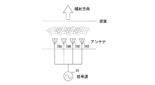
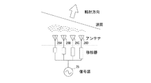
図5に示す位相式の計測装置40では、複数の分配/合成器41a〜41cと複数のアンテナ26a〜26c毎に設けた移相器42a〜42dを備え、各アンテナ26a〜26dから輻射される電波の位相を変えることによって、図6及び図7に示すように電波の輻射方向を変化させながら、電波の送信と受信を行い、計測した移動体1の速度が最も速くなる方向が移動体1の移動方向であり、このときの速度が真の速度であるとする。
5 includes a plurality of distributors /
このように位相式の計測装置は、機械的な駆動機構を設ける必要がないので、高速に電波の輻射方向を変化させることができる。 As described above, the phase-type measuring device does not need to be provided with a mechanical drive mechanism, and therefore can change the radiation direction of radio waves at high speed.
しかしながら、位相式の計測装置40では、複数の分配/合成器41a〜41cと移相器42a〜42dを直列接続するため、送受信回路25とアンテナ26a〜26dとの間を伝搬する信号の減衰が大きくなる。さらに、複数の分配/合成器41a〜41cと移相器42a〜42dの接続回路が複雑になるとともにコスト高になるという問題点があった。
However, in the phase-
本発明の目的は上記の問題点に鑑み、機械的な駆動機構を使用せずに電波の輻射方向を高速に変化して移動体の速度と移動方向の角度を計測できる移動体の速度・角度計測装置を提供することである。 SUMMARY OF THE INVENTION In view of the above problems, the object of the present invention is the speed and angle of a moving body capable of measuring the speed of the moving body and the angle of the moving direction by changing the radiation direction of the radio wave at high speed without using a mechanical drive mechanism. It is to provide a measuring device.
本発明は上記の目的を達成するために、指向性を有するアンテナに所定周波数の高周波信号を供給し、該アンテナから前記周波数の電波を移動体に向けて輻射し、前記移動体からの反射波を前記アンテナによって受信し、前記反射波の高周波信号の周波数を検出してドップラー法を用いて前記移動体の速度を計測する移動体の速度・角度計測装置であって、電波の輻射方向が異なるように設定された複数の前記指向性を有するアンテナと、制御信号に基づいて前記輻射波となる高周波信号を送信する送信手段と、前記反射波の高周波信号を受信する受信手段と、前記送信手段の高周波信号出力端子及び前記受信手段の高周波信号入力端子と前記複数のアンテナの給電端子との接続を前記制御信号に基づいて切り替える半導体素子からなる切替器と、データ記憶手段と、基準方向に対する前記各アンテナの指向性の方向のデータが記憶されているアンテナ方向データ記憶手段と、前記制御信号による前記切替器の切替タイミングに基づいて、前記電波をアンテナから輻射した直後に前記移動体によって反射され該アンテナに入射した反射波の高周波信号を前記受信手段から入力し、該高周波信号の信号強度と前記移動体の速度を求め、該求めた信号強度と速度のデータを対応させて一時記憶手段に記憶させる検出値取得手段と、前記切替タイミングの所定回数毎に、前記アンテナ方向データ記憶手段に記憶されているデータ及び前記一時記憶手段に記憶されている信号強度データを用いて前記所定回数内における前記信号強度の時間推移に基づいて信号強度が最も大きくなる方向を前記基準方向に対する前記移動体の移動方向として該移動体の移動方向の角度と該角度に対応する移動体の速度を求めて前記データ記憶手段に記憶する検出結果取得手段とを備えていることを特徴とする移動体の速度・角度計測装置を提案する。 In order to achieve the above object, the present invention supplies a high-frequency signal having a predetermined frequency to an antenna having directivity, radiates a radio wave of the frequency from the antenna toward the moving body, and reflects the reflected wave from the moving body. Is a speed / angle measurement apparatus for a moving body that detects the frequency of the high-frequency signal of the reflected wave and measures the speed of the moving body using the Doppler method, and the radiation direction of the radio waves is different A plurality of antennas having directivity set as described above, transmitting means for transmitting a high-frequency signal to be the radiated wave based on a control signal, receiving means for receiving the high-frequency signal of the reflected wave, and the transmitting means Switching comprising a semiconductor element that switches connection between the high-frequency signal output terminal and the high-frequency signal input terminal of the receiving means and the feeding terminals of the plurality of antennas based on the control signal And the data storage means, the antenna direction data storage means for storing the directionality data of each antenna with respect to a reference direction, and the radio wave from the antenna based on the switching timing of the switch by the control signal. A high-frequency signal of a reflected wave reflected by the moving body and incident on the antenna immediately after radiating from is input from the receiving means, and the signal strength of the high-frequency signal and the speed of the moving body are obtained, and the obtained signal strength and Detection value acquisition means for storing speed data in correspondence in the temporary storage means, and data stored in the antenna direction data storage means and the temporary storage means for every predetermined number of times of the switching timing. Based on the time transition of the signal strength within the predetermined number of times using signal strength data, And a detection result acquiring means for obtaining an angle of the moving direction of the moving body as a moving direction of the moving body with respect to a reference direction and a speed of the moving body corresponding to the angle and storing the speed in the data storing means. We propose a speed / angle measurement device for moving bodies.
本発明の移動体の速度・角度計測装置によれば、送信手段及び受信手段は制御信号に基づいて切替器によって各アンテナに順次接続が切り替えられる。また、制御信号による切替器の切替タイミングに基づいて、電波をアンテナから輻射した直後に移動体によって反射され該アンテナに入射した反射波の高周波信号を受信手段から入力し、移動体の速度が求められ、該求められた速度のデータが一時記憶手段に記憶される。さらに、切替タイミングの所定回数毎に、アンテナ方向データ記憶手段に記憶されているデータ及び前記一時記憶手段に記憶されている速度データに基づいて前記所定回数内における信号強度の時間推移に基づいて信号強度が最も大きくなる方向を基準方向に対する移動体の移動方向として該移動体の移動方向の角度と該角度に対応する移動体の速度が求められてデータ記憶手段に記憶される。 According to the moving body speed / angle measuring apparatus of the present invention, the transmitting means and the receiving means are sequentially switched to each antenna by the switch based on the control signal. Also, based on the switching timing of the switch by the control signal, the high-frequency signal of the reflected wave that is reflected by the moving body and incident on the antenna immediately after radiating the radio wave from the antenna is input from the receiving means, and the speed of the moving body is obtained. The obtained speed data is stored in the temporary storage means. Further, at every predetermined number of switching timings, the signal is based on the time transition of the signal strength within the predetermined number based on the data stored in the antenna direction data storage unit and the speed data stored in the temporary storage unit. The direction in which the intensity is the largest is the moving direction of the moving body relative to the reference direction, and the angle of the moving body and the speed of the moving body corresponding to the angle are obtained and stored in the data storage means.
本発明の移動体の速度・角度計測装置によれば、指向性の異なる複数のアンテナを備え、反射波の信号強度の時間推移に基づいて信号強度が最も大きくなる方向を移動体の移動方向として検出しているので、従来に比べて移動体の真の速度に近い速度を検出することができると共に移動体の移動方向を検出することができる。また、各アンテナと送受信手段との接続切り替えを半導体素子からなる切替器によって行っているため、従来例のような複雑な回転機構或いは複数の移相器や分配/合成器を用いなくてすむので、高速切り替え駆動が可能になるとともに複雑な接続回路が不要になり、コストを低減することができる。 According to the velocity / angle measuring apparatus for a moving body of the present invention, a plurality of antennas having different directivities are provided, and the direction in which the signal intensity is the largest based on the time transition of the signal intensity of the reflected wave is set as the moving direction of the moving body. Since it detects, the speed close | similar to the true speed of a moving body compared with the past can be detected, and the moving direction of a moving body can be detected. In addition, since the connection switching between each antenna and the transmission / reception means is performed by a switching device made of a semiconductor element, it is not necessary to use a complicated rotating mechanism or a plurality of phase shifters or distributors / combiners as in the conventional example. In addition, high-speed switching driving is possible, and a complicated connection circuit is not necessary, thereby reducing costs.
次に、本発明の一実施形態を図面を参照して説明する。 Next, an embodiment of the present invention will be described with reference to the drawings.
本実施形態では、本発明の一具体例として、ゴルフ場においてショットしたゴルフボールを移動体としてゴルフボールの速度と移動方向の角度を計測する装置として説明する。 In this embodiment, as a specific example of the present invention, a golf ball shot on a golf course will be described as a moving body, and a device for measuring the speed of the golf ball and the angle in the moving direction will be described.
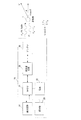
図1に示すように、本実施形態の移動体の速度・角度計測装置(以下、本装置と称する)10は、MCU(マイクロコンピュータ)11、電源部12、操作部13、表示部14、送受信部15、信号切替器16、記憶部17、N個(Nは自然数)のアンテナ18-1〜18-Nを備えている。
As shown in FIG. 1, a moving body speed / angle measuring device (hereinafter referred to as this device) 10 of this embodiment includes an MCU (microcomputer) 11, a
MCU11は電源部12から供給される電力によって動作し、操作部13から入力される指示に基づいて動作する。また、MCU11は、操作部13を介して入力された指示に基づいて信号切替器15を切替ながら送受信部15による送信と受信を制御する。さらに、MCU11は、送受信部15によってアンテナ18-1〜18-Nから輻射した電波の周波数と、アンテナ18-1〜18-Nを介して送受信部15より入力した高周波信号の周波数(移動体1からの反射波の周波数)とに基づいてドップラー法を用いて移動体1の速度と移動体1の移動方向の角度を求めて記憶部17に記憶すると共に表示部14に表示する。
The MCU 11 operates with power supplied from the
操作部13はスイッチ或いはタッチパネルなどを有し、操作者がMCU11に対して指示を入力できるようにする。
The
表示部14はMCU11からの表示指示に基づいて移動体1の速度と角度を表示する。
The
送受信部15はMCU11からの指示に基づいて24GHz帯の周波数f1の高周波信号を信号切替器16を介してアンテナ18-1〜18-Nに供給すると共に、アンテナ18-1〜18-Nによって受信した高周波信号を受信し、送信した高周波信号の周波数f1と受信した高周波信号の周波数f2の値からドップラー法によって移動体1の速度を算出し、算出した速度の値と受信した高周波信号の強度の値をデジタルデータとしてMCU11に送出する。
The transmission /
信号切替器16は、MESFET(Metal-Semiconductor Field Effect Transistor)或いはMEMS(Micro Electro Mechanical Systems)等の半導体素子からなり、MCU11から入力した制御信号CSに基づいてアンテナ18-1〜18-Nの中の何れか1つと送受信部15とを接続する。
The
記憶部17は、書き換え可能な不揮発性ROMや磁気ディスク装置などからなり、一時記憶領域と、アンテナ指向性情報記憶領域と、速度等データ記憶領域を備えている。一時記憶領域はMCU11によって一時的にデータが格納される領域であり、速度等データ記憶領域はMCU11によって求められた速度データと角度データが記憶される。また、アンテナ指向性データ記憶領域には、基準方向の角度を0度としたときの各アンテナの指向性方向の角度データが予め記憶されている。
The
アンテナ18-1〜18-Nのそれぞれは指向性を有するアンテナであり、それぞれの指向性方向が異なる方向となるように装置10の直方体形状の筐体の一面或いは平面状のアンテナ固定基板の一面などに固定されている。また、本実施形態では、アンテナ18-1〜18-Nが固定されている面に対して直角な方向に基準方向が設定されており、基準方向が水平面内に位置するように装置10を設置したときにアンテナ18-1〜18-Nの指向性方向が水平面内の角度と垂直面内の角度の双方或いは何れか一方をもつように複数のアンテナ18-1〜18-Nが設けられている。
Each of the antennas 18-1 to 18-N is an antenna having directivity, and is one surface of a rectangular parallelepiped casing or one surface of a planar antenna fixing substrate so that the directivity directions thereof are different from each other. Etc. are fixed. In the present embodiment, the reference direction is set in a direction perpendicular to the surface to which the antennas 18-1 to 18-N are fixed, and the
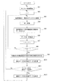
次に、本装置10の詳細な動作を図2のフローチャートを参照して説明する。
Next, the detailed operation of the
ショットする際のゴルフボール(移動体1)の速度と角度を本装置10を用いて計測する際に、操作者はゴルフボールが飛んで行く方向を考慮して本装置10の基準方向を設定して本装置10を固定した後、本装置10を駆動させる。ここで、上記のようにアンテナ18-1〜18-Nが同一面上に固定され、ゴルフボールが飛んで行く方向を考慮して本装置10の基準方向が設定されると、飛んでいくゴルフボールから各アンテナ18-1〜18-Nまでの距離がほぼ等しくなるので、計測される信号強度の誤差を低減することができる。
When measuring the speed and angle of the golf ball (moving body 1) at the time of shot using the
操作者によって本装置10の駆動が開始されると、MCU11はタイマー計時を開始し(SA1)、変数iを1に設定する(SA2)。
When driving of the
次いで、MCU11は信号切替器16へ制御信号CSを出力して送受信部15をi番目のアンテナ18-iに接続する(SA3)とともに、送受信部15に対して送信命令を出力する(SA4)。これにより、送受信部15から高周波信号が所定時間だけアンテナ18-iに供給され、アンテナ18-iから電波が輻射される。
Next, the
また、送受信部15からアンテナ18-iに高周波信号が供給された後、送受信部15は受信状態として待機し、アンテナ18-iを介して移動体1からの反射波の高周波信号を入力したときに、この高周波信号の信号強度を検出するとともに、送信した高周波信号の周波数f1と受信した高周波信号の周波数f2からドップラー法を用いて移動体1の速度を算出し、信号強度の値と速度の値のデジタルデータをMCU11に出力する。
In addition, after the high frequency signal is supplied from the transmission /
送受信部15から信号強度の値と速度の値のデジタルデータを入力(SA5)したMCU11は、これらのデータを記憶部17の一時記憶領域に記憶(SA6)した後、変数iに1を加算し(SA7)、変数iが(N+1)に等しいか否かを判定する(SA8)。この判定の結果、変数iが(N+1)に等しく無いときは前記SA3の処理に移行しする。また、変数iが(N+1)に等しいときは、MCU11は、データ記憶部17の一時記憶領域に格納されている信号強度の値と速度の値を読み出し、これらのデータと周知のビームフォーマー法を用いて基準方向に対するゴルフボールの移動方向の角度及びそのときの速度を求め(SA9)、求めた角度と速度のデータを対応づけてデータ記憶部17の速度等データ記憶領域に格納するとともに一時記憶領域に格納されているデータを消去する(SA10)。
The
次に、MCU11はタイマーの計時時間が時間T1を経過したが否かを判定し(SA11)、時間T1を経過していないときは前記SA2の処理に移行する。また、タイマーの計時時間が時間T1を経過したときは、MCU11は速度等データ記憶領域に格納されている速度データの中で最も大きい速度データとこれに対応する角度データを表示部14の表示器に表示するとともに速度等データ記憶領域に格納されているデータを消去する(SA12)。この後、前記SA1の処理に移行する。
Next, the
なお、本実施形態では信号切替器16をns(1×10⁻⁹秒)単位で切り替えられるようすると共に操作部13を介して操作者が切り替え間隔時間を変えられるようにしている。このように切り替え間隔時間を変えられることにより、移動体1の種類によって移動体の速度が異なっても適切にアンテナを切り替えることができる。たとえば、ゴルフボールに代えて野球ボールやソフトボールなど速度及び角度を計測する際に、それぞれのボールの速さが異なるので、速さにあったアンテナ切り替え間隔時間を設定することができる。これにより、移動体の種類が変わり移動速度が変わっても、的確に速度と角度を計測することができる。
In the present embodiment, the
以上説明したように、本実施形態の移動体の速度・角度計測装置10によれば、指向性の異なる複数のアンテナ18-1〜18-Nを備え、反射波の信号強度の時間推移に基づいて信号強度が最も大きくなる方向を移動体の移動方向として検出しているので、従来に比べて移動体の真の速度に近い速度を検出することができると共に移動体の移動方向を検出することができる。また、各アンテナ18-1〜18-Nと送受信部15との接続切り替えを半導体素子からなる切替器16によって行っているため、従来例のような複雑な回転機構或いは複数の移相器や分配/合成器を用いなくてすむので、高速切り替え駆動が可能になるとともに複雑な接続回路が不要になり、コストを低減することができる。
As described above, according to the velocity /
なお、本実施形態では時間T1を例えば10msに設定しているが、移動体の種類や速さに応じて適宜設定することが好ましい。 In the present embodiment, the time T1 is set to 10 ms, for example, but it is preferable to set the time T1 appropriately according to the type and speed of the moving body.
また、本実施形態ではビームフォーマー法を用いて移動体の角度を計測しているが、一時記憶領域に記憶されているデータの中で信号強度の値が最も大きいときの速度と角度を移動体の速度と角度としてもよい。 In this embodiment, the angle of the moving body is measured by using the beam former method. However, the speed and angle when the signal intensity value is the largest among the data stored in the temporary storage area are moved. It may be the speed and angle of the body.
本発明は、機械的な駆動機構を使用せずに電波の輻射方向を高速に変化して移動体の速度と移動方向の角度を計測できる移動体の速度・角度計測装置に関するものである。 The present invention relates to a moving body speed / angle measuring apparatus capable of measuring the speed of a moving body and the angle of the moving direction by changing the radiation direction of radio waves at high speed without using a mechanical drive mechanism.
1…移動体、10…移動体の速度・角度計測装置、11…MCU、12…電源部、13…操作部、14…表示部、15…送受信部、16…信号切替器、17…記憶部、18-1〜18-N…アンテナ。
DESCRIPTION OF
Claims (8)
電波の輻射方向が異なるように設定された複数の前記指向性を有するアンテナと、
制御信号に基づいて前記輻射波となる高周波信号を送信する送信手段と、
前記反射波の高周波信号を受信する受信手段と、
前記送信手段の高周波信号出力端子及び前記受信手段の高周波信号入力端子と前記複数のアンテナの給電端子との接続を前記制御信号に基づいて切り替える半導体素子からなる切替器と、
データ記憶手段と、
基準方向に対する前記各アンテナの指向性の方向のデータが記憶されているアンテナ方向データ記憶手段と、
前記制御信号による前記切替器の切替タイミングに基づいて、前記電波をアンテナから輻射した直後に前記移動体によって反射され該アンテナに入射した反射波の高周波信号を前記受信手段から入力し、該高周波信号の信号強度と前記移動体の速度を求め、該求めた信号強度と速度のデータを対応させて一時記憶手段に記憶させる検出値取得手段と、
前記切替タイミングの所定回数毎に、前記アンテナ方向データ記憶手段に記憶されているデータ及び前記一時記憶手段に記憶されている信号強度データを用いて前記所定回数内における前記信号強度の時間推移に基づいて信号強度が最も大きくなる方向を前記基準方向に対する前記移動体の移動方向として該移動体の移動方向の角度と該角度に対応する移動体の速度を求めて前記データ記憶手段に記憶する検出結果取得手段とを備えている
ことを特徴とする移動体の速度・角度計測装置。 A high frequency signal of a predetermined frequency is supplied to an antenna having directivity, a radio wave of the frequency is radiated from the antenna toward a moving body, a reflected wave from the moving body is received by the antenna, and a high frequency of the reflected wave is received. A moving body speed / angle measuring device that detects the frequency of a signal and measures the speed of the moving body using a Doppler method,
A plurality of antennas having the directivity set so that the radiation directions of radio waves are different;
Transmitting means for transmitting a high-frequency signal to be the radiated wave based on a control signal;
Receiving means for receiving a high-frequency signal of the reflected wave;
A switch composed of a semiconductor element that switches connection between the high-frequency signal output terminal of the transmission means and the high-frequency signal input terminal of the reception means and the power supply terminals of the plurality of antennas based on the control signal;
Data storage means;
Antenna direction data storage means in which data of the directionality of each antenna with respect to a reference direction is stored;
Based on the switching timing of the switch by the control signal, a high-frequency signal of a reflected wave reflected by the moving body and incident on the antenna immediately after radiating the radio wave from the antenna is input from the receiving means, and the high-frequency signal Detection value acquisition means for determining the signal intensity of the moving body and the speed of the moving body, and storing the obtained signal intensity and speed data in correspondence in the temporary storage means;
Based on the time transition of the signal strength within the predetermined number of times using the data stored in the antenna direction data storage unit and the signal strength data stored in the temporary storage unit at every predetermined number of times of the switching timing. As a result, the direction in which the signal intensity becomes the largest is the moving direction of the moving body with respect to the reference direction, and the angle of the moving direction of the moving body and the speed of the moving body corresponding to the angle are obtained and stored in the data storage means A speed / angle measuring apparatus for a moving body, comprising: an acquisition means.
ことを特徴とする請求項1に記載の移動体の速度・角度計測装置。 The detection result acquisition means sets the directionality of the antenna at which the obtained speed is the largest as the moving direction of the moving body, and the angle formed by the directivity direction and the reference direction is the angle of the moving direction of the moving body. The speed / angle measuring apparatus for a moving body according to claim 1.
ことを特徴とする請求項1又は2に記載の移動体の速度・角度計測装置。 The apparatus for measuring a speed / angle of a moving body according to claim 1 or 2, further comprising means for changing a switching interval of the switch based on an operation of an operator.
ことを特徴とする請求項1乃至3の何れかに記載の移動体の速度・角度計測装置。 The detection result acquisition means sets the speed and angle at the maximum speed within 10 ms every 10 ms based on the data stored in the data storage means as the speed and angle of the moving body. The apparatus for measuring a speed / angle of a moving body according to any one of claims 1 to 3, further comprising: means.
ことを特徴とする請求項1乃至4の何れかに記載の移動体の速度・角度計測装置。 5. The moving body speed / angle measuring device according to claim 1, further comprising display means for displaying the speed and angle acquired by the detection result acquiring means.
ことを特徴とする請求項1乃至5の何れかに記載の移動体の速度・角度計測装置。 6. The moving body speed / angle measuring apparatus according to claim 1, wherein each of the plurality of antennas is disposed at a substantially equal distance from the moving body.
ことを特徴とする請求項1乃至6の何れかに記載の移動体の速度・角度計測装置。 The detection result acquisition means calculates the angle and speed of the moving direction of the moving body with the directivity direction of the antenna receiving the signal having the maximum signal strength within the predetermined number of times as the moving direction of the moving body, and stores the data The means for storing in the means is provided. The moving body speed / angle measuring device according to any one of claims 1 to 6,
ことを特徴とする請求項1乃至6の何れかに記載の移動体の速度・角度計測装置。 The detection result acquisition means includes means for obtaining an angle and speed in the moving direction of the moving body using a beamformer method based on a time transition of the signal intensity within the predetermined number of times and storing the angle in the data storage means. The apparatus for measuring a speed and angle of a moving body according to any one of claims 1 to 6.
Priority Applications (2)
| Application Number | Priority Date | Filing Date | Title |
|---|---|---|---|
| JP2013254770A JP2015114143A (en) | 2013-12-10 | 2013-12-10 | Speed and angle measurement device for moving body |
| PCT/JP2014/082524 WO2015087867A1 (en) | 2013-12-10 | 2014-12-09 | Speed/angle measurement device for mobile object |
Applications Claiming Priority (1)
| Application Number | Priority Date | Filing Date | Title |
|---|---|---|---|
| JP2013254770A JP2015114143A (en) | 2013-12-10 | 2013-12-10 | Speed and angle measurement device for moving body |
Publications (1)
| Publication Number | Publication Date |
|---|---|
| JP2015114143A true JP2015114143A (en) | 2015-06-22 |
Family
ID=53371169
Family Applications (1)
| Application Number | Title | Priority Date | Filing Date |
|---|---|---|---|
| JP2013254770A Pending JP2015114143A (en) | 2013-12-10 | 2013-12-10 | Speed and angle measurement device for moving body |
Country Status (2)
| Country | Link |
|---|---|
| JP (1) | JP2015114143A (en) |
| WO (1) | WO2015087867A1 (en) |
Cited By (1)
| Publication number | Priority date | Publication date | Assignee | Title |
|---|---|---|---|---|
| JP2022543179A (en) * | 2019-05-28 | 2022-10-11 | コアエイチダブリュー セミコンダクター オイ | Antenna Soft Switching Solution for AoD Direction Finding Transmitters |
Family Cites Families (3)
| Publication number | Priority date | Publication date | Assignee | Title |
|---|---|---|---|---|
| JP2595907B2 (en) * | 1994-08-30 | 1997-04-02 | 日本電気株式会社 | Radio wave arrival direction detector |
| JP2012078172A (en) * | 2010-09-30 | 2012-04-19 | Panasonic Corp | Radio communication device |
| JP5824857B2 (en) * | 2011-04-28 | 2015-12-02 | 横浜ゴム株式会社 | Ball game simulator device and ball game simulation method |
-
2013
- 2013-12-10 JP JP2013254770A patent/JP2015114143A/en active Pending
-
2014
- 2014-12-09 WO PCT/JP2014/082524 patent/WO2015087867A1/en not_active Ceased
Cited By (2)
| Publication number | Priority date | Publication date | Assignee | Title |
|---|---|---|---|---|
| JP2022543179A (en) * | 2019-05-28 | 2022-10-11 | コアエイチダブリュー セミコンダクター オイ | Antenna Soft Switching Solution for AoD Direction Finding Transmitters |
| JP7395619B2 (en) | 2019-05-28 | 2023-12-11 | コアエイチダブリュー セミコンダクター オイ | Antenna soft switching solution for AoD direction finding transmitter |
Also Published As
| Publication number | Publication date |
|---|---|
| WO2015087867A1 (en) | 2015-06-18 |
Similar Documents
| Publication | Publication Date | Title |
|---|---|---|
| US9835722B2 (en) | Synthetic aperture RFID handheld with tag location capability | |
| US9470782B2 (en) | Method and apparatus for increasing angular resolution in an automotive radar system | |
| CN110297211A (en) | A kind of localization method and electronic equipment | |
| JP2009103457A (en) | Radar device and holding member | |
| JP2009103458A (en) | Radar output optimization method and radar output optimization device | |
| US20240372418A1 (en) | Wireless charging method and apparatus, and electronic device | |
| KR100599610B1 (en) | Satellite tracking antenna system and satellite tracking method using sub-reflection plate rotation period correction | |
| KR102197086B1 (en) | Apparatus and method for tracking target for antiaircraft | |
| JP2021181997A (en) | Rader system | |
| JP5380267B2 (en) | Guiding device and target detection method | |
| JP2015114143A (en) | Speed and angle measurement device for moving body | |
| KR101502551B1 (en) | Apparatus for tracking target bsed on hybrid technique | |
| CN105578588A (en) | Base station synchronizing and positioning method and equipment | |
| JP2017125819A (en) | Antenna tilt device and electromagnetic wave measuring device | |
| JPWO2017169300A1 (en) | Antenna apparatus, radar system, and antenna rotation method | |
| JPH11271418A (en) | Radio position locating system, device and method | |
| JP2018159550A (en) | Radar control device and radar transmission power control method | |
| JP2004132827A (en) | Radar apparatus and radar system | |
| US10001554B2 (en) | Radar signal processing method and apparatus | |
| FI20215547A1 (en) | Vibration measurements of objects | |
| JP2014159975A (en) | Radar device and method for controlling the same | |
| JP6168913B2 (en) | Radar equipment | |
| KR20190136218A (en) | Method for radiated direction tracking based on antenna using radio channel response characteristic of singnal | |
| JP4788290B2 (en) | Pulse radar equipment | |
| KR102429917B1 (en) | Apparatus for measuring radio signal for device including different antennas and method for the same |