JP2015114135A - Battery control device - Google Patents
Battery control device Download PDFInfo
- Publication number
- JP2015114135A JP2015114135A JP2013254548A JP2013254548A JP2015114135A JP 2015114135 A JP2015114135 A JP 2015114135A JP 2013254548 A JP2013254548 A JP 2013254548A JP 2013254548 A JP2013254548 A JP 2013254548A JP 2015114135 A JP2015114135 A JP 2015114135A
- Authority
- JP
- Japan
- Prior art keywords
- voltage
- storage battery
- value
- current
- change
- Prior art date
- Legal status (The legal status is an assumption and is not a legal conclusion. Google has not performed a legal analysis and makes no representation as to the accuracy of the status listed.)
- Granted
Links
Images
Classifications
-
- H—ELECTRICITY
- H02—GENERATION; CONVERSION OR DISTRIBUTION OF ELECTRIC POWER
- H02J—ELECTRIC POWER NETWORKS; CIRCUIT ARRANGEMENTS OR SYSTEMS FOR SUPPLYING OR DISTRIBUTING ELECTRIC POWER; SYSTEMS FOR STORING ELECTRIC ENERGY
- H02J7/00—Circuit arrangements for charging or discharging batteries or for supplying loads from batteries
- H02J7/90—Regulation of charging or discharging current or voltage
- H02J7/96—Regulation of charging or discharging current or voltage in response to battery voltage
- H02J7/963—Regulation of charging or discharging current or voltage in response to battery voltage in response to battery voltage gradient
-
- G—PHYSICS
- G01—MEASURING; TESTING
- G01R—MEASURING ELECTRIC VARIABLES; MEASURING MAGNETIC VARIABLES
- G01R31/00—Arrangements for testing electric properties; Arrangements for locating electric faults; Arrangements for electrical testing characterised by what is being tested not provided for elsewhere
- G01R31/36—Arrangements for testing, measuring or monitoring the electrical condition of accumulators or electric batteries, e.g. capacity or state of charge [SoC]
- G01R31/382—Arrangements for monitoring battery or accumulator variables, e.g. SoC
- G01R31/3842—Arrangements for monitoring battery or accumulator variables, e.g. SoC combining voltage and current measurements
-
- H—ELECTRICITY
- H02—GENERATION; CONVERSION OR DISTRIBUTION OF ELECTRIC POWER
- H02J—ELECTRIC POWER NETWORKS; CIRCUIT ARRANGEMENTS OR SYSTEMS FOR SUPPLYING OR DISTRIBUTING ELECTRIC POWER; SYSTEMS FOR STORING ELECTRIC ENERGY
- H02J7/00—Circuit arrangements for charging or discharging batteries or for supplying loads from batteries
- H02J7/14—Circuit arrangements for charging or discharging batteries or for supplying loads from batteries for charging batteries from dynamo-electric generators driven at varying speed, e.g. on vehicle
-
- Y—GENERAL TAGGING OF NEW TECHNOLOGICAL DEVELOPMENTS; GENERAL TAGGING OF CROSS-SECTIONAL TECHNOLOGIES SPANNING OVER SEVERAL SECTIONS OF THE IPC; TECHNICAL SUBJECTS COVERED BY FORMER USPC CROSS-REFERENCE ART COLLECTIONS [XRACs] AND DIGESTS
- Y02—TECHNOLOGIES OR APPLICATIONS FOR MITIGATION OR ADAPTATION AGAINST CLIMATE CHANGE
- Y02E—REDUCTION OF GREENHOUSE GAS [GHG] EMISSIONS, RELATED TO ENERGY GENERATION, TRANSMISSION OR DISTRIBUTION
- Y02E60/00—Enabling technologies; Technologies with a potential or indirect contribution to GHG emissions mitigation
- Y02E60/10—Energy storage using batteries
Landscapes
- Engineering & Computer Science (AREA)
- Power Engineering (AREA)
- Physics & Mathematics (AREA)
- General Physics & Mathematics (AREA)
- Secondary Cells (AREA)
- Charge And Discharge Circuits For Batteries Or The Like (AREA)
- Tests Of Electric Status Of Batteries (AREA)
Abstract
Description
本発明は、蓄電池において充放電可能な電力を推定する電池制御装置に関する。 The present invention relates to a battery control device that estimates power that can be charged and discharged in a storage battery.
例えば、蓄電池が車載用蓄電池として用いられる場合に、回生発電で発電された電力を蓄電池に対して充電するときには、蓄電池に充電可能な電力の推定が行われる。また、蓄電池から車両の主機としてのモータに電力を供給する際、蓄電池からモータに放電可能な電力の推定が行われる。 For example, when the storage battery is used as an in-vehicle storage battery, when the power generated by regenerative power generation is charged to the storage battery, the power that can be charged in the storage battery is estimated. Further, when power is supplied from the storage battery to the motor as the main machine of the vehicle, the power that can be discharged from the storage battery to the motor is estimated.
蓄電池に対して充放電可能な電力を推定する充放電可能電力推定装置が知られている(例えば、特許文献1)。特許文献1に記載の技術では、蓄電池の端子間電圧の変化と、電流の増減変化によって生じる電圧変化と、を等しいとみなして、蓄電池の充放電可能電力及び放電可能電力を推定する。 2. Description of the Related Art A chargeable / dischargeable power estimation device that estimates chargeable / dischargeable power for a storage battery is known (for example, Patent Document 1). In the technique described in Patent Document 1, the chargeable / dischargeable power and the dischargeable power of the storage battery are estimated by regarding the change in the inter-terminal voltage of the storage battery and the voltage change caused by the increase / decrease in current as equal.
ここで、蓄電池において行われる充電及び放電は、所定の期間において行われ、その充放電が行われる期間において、蓄電池の内部に対して電荷が蓄積される。つまり、蓄電池の通電時において、出力端子に電荷が流入する場合、その一部が蓄電池内部に蓄積される。この電荷の蓄積が生じる場合、蓄電池の端子間電圧の変化分には、内部抵抗値×通電電流として求められる電圧変化分と、蓄電池内部の電荷の蓄積により生じる電圧変化分とが含まれることになる。この場合、蓄電池の端子間電圧の変化と、電流の増減変化によって生じる電圧変化とを等しいとみなす上記技術では、電荷の蓄積又は放出によって生じる電圧変化分が考慮されておらず、端子間電圧の予測値の精度が悪化する。その結果、充放電可能な電力を精度よく算出することができないと考えられる。 Here, charging and discharging performed in the storage battery are performed in a predetermined period, and charges are accumulated in the storage battery in the period in which the charging and discharging are performed. That is, when electric charge flows into the output terminal during energization of the storage battery, a part of the charge is stored inside the storage battery. When this charge accumulation occurs, the change in the voltage between the terminals of the storage battery includes the voltage change obtained as the internal resistance value × the energization current and the voltage change caused by the charge accumulation inside the storage battery. Become. In this case, in the above-mentioned technique that considers the change in the voltage between the terminals of the storage battery and the voltage change caused by the increase / decrease in the current to be equal, the voltage change caused by the charge accumulation or discharge is not taken into consideration. The accuracy of the predicted value deteriorates. As a result, it is considered that the chargeable / dischargeable power cannot be accurately calculated.
本発明は、上記課題を解決するためになされたものであり、蓄電池において充放電可能な電力を精度よく算出可能な電池制御装置を提供することを主たる目的とする。 The present invention has been made in order to solve the above-described problems, and a main object of the present invention is to provide a battery control device capable of accurately calculating power that can be charged and discharged in a storage battery.
本発明は、蓄電池(10)に所定期間で電流を流して充電又は放電を行い、その充電又は放電により前記蓄電池の端子間電圧(V)が変化する場合において、前記所定期間の経過後における充放電可能な電力(W)を算出する電池制御装置(50)であって、前記蓄電池の充電又は放電を行う場合に、前記所定期間における前記端子間電圧の変化量(ΔV)のうち、前記蓄電池の内部における電荷の蓄積に起因する電圧変化分である特定変化量(ΔVc,ΔOCV)を算出する特定変化量算出手段と、前記所定期間の経過後に前記端子間電圧を所定電圧まで変化させるのに要する前記蓄電池に流れる通電電流(I^(Ta))と、前記所定期間において所定電流を流した場合に前記所定期間の経過後における前記蓄電池の端子間電圧(V^(Ta))とのいずれかを予測対象値とし、前記特定変化量算出手段により算出した特定変化量を用いて、前記予測対象値を算出する予測値算出手段と、前記予測値算出手段により算出した予測対象値に基づいて、前記充放電可能な電力を算出する電力算出手段と、を備えることを特徴とする。 In the present invention, charging or discharging is performed by passing a current through the storage battery (10) for a predetermined period, and when the inter-terminal voltage (V) of the storage battery changes due to the charging or discharging, charging after the predetermined period has elapsed. A battery control device (50) for calculating dischargeable power (W), wherein, when charging or discharging the storage battery, the storage battery among the amount of change (ΔV) in the inter-terminal voltage during the predetermined period Specific change amount calculating means for calculating a specific change amount (ΔVc, ΔOCV) which is a voltage change amount caused by charge accumulation in the inside of the device, and for changing the inter-terminal voltage to a predetermined voltage after the predetermined period has elapsed. The required energization current (I ^ (Ta)) flowing through the storage battery and the terminal voltage (V ^ (T) of the storage battery after the predetermined period when a predetermined current is passed in the predetermined period. )) As a prediction target value, and using the specific change amount calculated by the specific change amount calculation means, a prediction value calculation means for calculating the prediction target value, and a prediction calculated by the prediction value calculation means And a power calculating means for calculating the chargeable / dischargeable power based on a target value.
電池制御装置は、蓄電池の端子から入出力される通電電流又は蓄電池の端子間電圧を調整することで充放電時の電力を制御する。蓄電池においては電流が流れることで充電又は放電が行われ、それに伴い蓄電池の端子間電圧が変化する。所定期間において蓄電池の端子間電圧が変化してΔV分の電圧変化が生じたとしても、その電圧変化量ΔVの全てが蓄電池の通電電流(出力端子から入出力される電流)に相関がある訳でなく、電圧変化量ΔVには、電池内部の状態変化に伴い生じた電圧変化分も含まれる。この電圧変化分は、蓄電池における電荷の蓄積に起因する電圧変化分(電荷の蓄積及び蓄積電荷の放出による電圧変化分)に相当する。ここで、電圧変化量ΔVのうち、蓄電池における電荷の蓄積に起因する電圧変化分を考慮せずに電流値や電圧値の予測を行い、その予測結果に基づいて電力制御を行う構成では、高精度な電力制御を実施できないものとなる。 The battery control device controls the power during charging and discharging by adjusting the energization current input / output from / to the storage battery terminal or the inter-terminal voltage of the storage battery. In the storage battery, charging or discharging is performed by the flow of current, and the inter-terminal voltage of the storage battery changes accordingly. Even if the voltage between the terminals of the storage battery changes during the predetermined period and a voltage change of ΔV occurs, all of the voltage change amount ΔV is correlated with the energization current (current input / output from the output terminal) of the storage battery. Instead, the voltage change amount ΔV includes a voltage change caused by a change in state inside the battery. This voltage change corresponds to a voltage change caused by charge accumulation in the storage battery (voltage change due to charge accumulation and discharge of accumulated charge). Here, in the voltage change amount ΔV, the current value and the voltage value are predicted without considering the voltage change due to the charge accumulation in the storage battery, and the power control is performed based on the prediction result. Accurate power control cannot be performed.
この点、上記構成では、蓄電池の充電又は放電を行う場合に、所定期間における端子間電圧の変化量のうち、蓄電池における電荷の蓄積又は放出に伴う電圧変化分である特定変化量を算出し、その特定変化量を用いて、予測対象値としての通電電流(電流予測値)又は端子間電圧(電圧予測値)を算出するようにした。また、その予測対象値に基づいて充放電可能な電力を算出するようにした。この場合、蓄電池における電荷の蓄積又は放出に伴う電圧変化分である特定変化量を考慮して電流予測又は電圧予測を行い、その予測結果に基づいて電力制御を実施できる。その結果、充放電可能な電力を精度良く算出することができる。 In this regard, in the above configuration, when charging or discharging the storage battery, among the amount of change in the voltage between the terminals in a predetermined period, a specific change amount that is a voltage change amount associated with charge accumulation or discharge in the storage battery is calculated, Using the specific change amount, an energization current (current prediction value) or a voltage between terminals (voltage prediction value) as a prediction target value is calculated. Moreover, the electric power which can be charged / discharged was calculated based on the prediction object value. In this case, it is possible to perform current prediction or voltage prediction in consideration of a specific change amount that is a voltage change amount due to charge accumulation or discharge in the storage battery, and to perform power control based on the prediction result. As a result, the chargeable / dischargeable power can be accurately calculated.
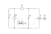
本実施形態における蓄電池10及び電池制御装置としての制御装置50を備える電気回路図を図1に示す。
An electric circuit diagram including the
蓄電池10及び制御装置50は、車両に搭載されている。蓄電池10は、交流−直流変換を行うインバータ21を介してモータジェネレータ22に接続されている。モータジェネレータ22に対して運動エネルギが供給され、モータジェネレータ22が発電機として機能する場合、蓄電池10はモータジェネレータ22から供給される電力によって充電される。また、モータジェネレータ22が動力源としてのモータとして機能する場合、蓄電池10はモータジェネレータ22に対して電力供給を行う。また、蓄電池10は、電気負荷20に接続され、電気負荷20に対し電力を供給する。なお、蓄電池10は、リチウムイオン蓄電池である。
The
蓄電池10と電気負荷20及びインバータ21とを接続する経路上には蓄電池10に流れる通電電流Iを検出するための電流センサ30が設けられており、蓄電池10の両端子には、その両端子間の電圧Vを検出するための電圧センサ40が設けられている。これら電流センサ30及び電圧センサ40はそれぞれ通電電流I及び端子間電圧Vに応じた検出信号を出力し、その検出信号は制御装置50に入力される。検出値取得手段としての制御装置50は、入力される信号に基づいて電流センサ30及び電圧センサ40による検出値を取得する。
A
制御装置50は、蓄電池10において充放電を開始する際、電流センサ30及び電圧センサ40から取得した検出値に基づいて、蓄電池10に対して充放電可能な電力の最大値である充放電可能電力を算出する。ここで充放電可能電力とは、蓄電池10に印加される端子間電圧を所定の目標電圧Vmとなるように調整した場合に蓄電池10において充放電される電力、及び、蓄電池10に流れる通電電流を所定の目標電流Imとなるように調整した場合に蓄電池10において充放電される電力のことを言う。目標電圧Vm、及び、目標電流Imは、例えば、蓄電池10が過充電及び過放電とならないような値に設定されている。そして、制御装置50は、充放電可能電力に基づいて、インバータ21の制御を行い、蓄電池10の端子間電圧V及び蓄電池10に流れる通電電流Iを調整する。
When the
蓄電池10の端子間電圧を充放電の開始時点(t=0)における電圧値V(0)から目標電圧Vmに変化させる場合に、充放電の開始時点からTa秒後(時刻Ta)における充放電可能電力を算出する方法を以下に示す。
When the voltage between the terminals of the
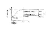
図2に示すように、端子間電圧VをV(0)からVmへと変化させる場合の電圧変化量ΔVは、通電電流の変化に伴う電圧変化量ΔVr、蓄電池10内部の容量成分の分極電圧の変化量ΔVc、開放電圧の変化量ΔOCVの和として表される。
ΔV=ΔVr+ΔVc+ΔOCV…(1)
以下、ΔVr,ΔVc,ΔOCVのそれぞれについて説明する。
As shown in FIG. 2, when the inter-terminal voltage V is changed from V (0) to Vm, the voltage change amount ΔV is the voltage change amount ΔVr accompanying the change in the energization current, and the polarization voltage of the capacity component inside the
ΔV = ΔVr + ΔVc + ΔOCV (1)
Hereinafter, each of ΔVr, ΔVc, and ΔOCV will be described.
蓄電池10の端子間電圧Vを変化させると、蓄電池10に流れる通電電流Iが変化する。この通電電流Iの変化によって、蓄電池10の内部抵抗における電圧降下が変化し、通電電流の変化に伴う電圧変化量ΔVrが生じる。その通電電流の変化に伴う電圧変化量ΔVrに応じて蓄電池10の端子間電圧Vが変化する。
When the inter-terminal voltage V of the
また、蓄電池10に電流が流れることで、蓄電池10の内部抵抗を構成する容量成分の分極状態が変化し、蓄電池10の端子間電圧Vが変化する。具体的には、蓄電池10の内部抵抗を構成する容量成分に対して電荷が蓄積又は放出されることで蓄電池10の内部の分極電圧Vcが変化し、その分極電圧の変化量ΔVcに応じて蓄電池10の端子間電圧Vが変化する。
In addition, when a current flows through the
また、充放電の開始時点から時刻Taまでの間、蓄電池10に電流Iが流れ、蓄電池10が充放電されることで、蓄電池10のSOC(State of Charge)が変化し、そのSOCの変化に応じて蓄電池10の開放電圧が変化する。そして、その開放電圧の変化量ΔOCVに応じて蓄電池10の端子間電圧Vが変化する。
In addition, the current I flows through the
つまり、所定期間において蓄電池10の端子間電圧Vが変化してΔV分の電圧変化が生じたとしても、その電圧変化量ΔVの全てが蓄電池10の通電電流(出力端子から入出力される電流)に相関がある訳でなく、電圧変化量ΔVには、電池内部の状態変化に伴い生じた電圧変化分も含まれる。この電圧変化分は、蓄電池10における電荷の蓄積に伴う電圧変化分(ΔVc,ΔOCV)に相当する。ここで、電圧変化量ΔVのうち、蓄電池10における電荷の蓄積に伴う電圧変化分を考慮せずに電流値や電圧値の予測を行い、その予測結果に基づいて電力制御を行う構成では、高精度な電力制御を実施できないものとなる。
That is, even if the voltage V between terminals of the
ここで、通電電流Iの変化量の予測値をΔI^、Ta秒後の蓄電池10の内部抵抗の値をRt(Ta)とする。この場合、下記式(2)のように、通電電流の変化に伴う電圧変化量ΔVrは、電流の変化量の予測値ΔI^とTa秒後の蓄電池10の内部抵抗の値Rt(Ta)の積として表すことができる。なお、ハット記号(^)は、対象の予測値を表すものとして用いている。
ΔVr=ΔI^・Rt(Ta)…(2)
充放電の開始時点において蓄電池10に流れる通電電流の検出値をI(0)とすると、時刻Taにおける蓄電池10に流れる電流の予測値I^(Ta)は、式(1)及び(2)を用いて、
I^(Ta)=I(0)+ΔI^
=I(0)+ΔVr/Rt(Ta)
=I(0)+(ΔV−ΔVc−ΔOCV)/Rt(Ta)…(3)
として表すことができる。つまり、通電電流の予測値I^(Ta)は、充放電の開始時点における電流の検出値I(0)及び電圧の検出値V(0)、開放電圧の変化量ΔOCV、分極電圧の変化量ΔVc、及び、時刻Taにおける蓄電池10の内部抵抗の値Rt(Ta)に基づいて算出できる。
Here, it is assumed that the predicted value of the change amount of the energization current I is ΔI ^, and the value of the internal resistance of the
ΔVr = ΔI ^ · Rt (Ta) (2)
Assuming that the detected value of the energization current flowing through the
I ^ (Ta) = I (0) + ΔI ^
= I (0) + ΔVr / Rt (Ta)
= I (0) + (ΔV−ΔVc−ΔOCV) / Rt (Ta) (3)
Can be expressed as That is, the predicted value I ^ (Ta) of the energization current is the detected current value I (0) and the detected voltage value V (0) at the start of charging / discharging, the open circuit voltage change amount ΔOCV, and the polarization voltage change amount. It can be calculated based on ΔVc and the value Rt (Ta) of the internal resistance of the
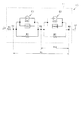
また、分極電圧Vcは、微少時間Δt秒前の分極電圧Vca及び蓄電池10に流れる通電電流Iに基づいて逐次的に算出することができる。以下、その方法を説明する。分極電圧Vcを算出するために用いる等価回路モデルを図3に示す。蓄電池10の等価回路は、容量成分を含む内部抵抗11と、内部抵抗11を除く電圧源12とから構成される。電圧源12の出力電圧は、定常状態において蓄電池10に電流が流れていない場合の蓄電池10の端子間電圧、即ち、開放電圧と等しい。
Further, the polarization voltage Vc can be sequentially calculated based on the polarization voltage Vca a minute time Δt seconds ago and the energization current I flowing through the
ここでは、内部抵抗11について、電流・電圧が変化した場合でも抵抗値が変化しない直流抵抗と、電流・電圧が変化した場合に抵抗値が変化する反応抵抗とから構成されることに着目し、モデル化を行っている。更に、蓄電池中での異なる反応に対応するべく、それぞれ時定数の異なる第1反応抵抗と第2反応抵抗とを用いて反応抵抗をモデル化している。具体的には、内部抵抗11は、直流抵抗を表すRs、第1反応抵抗を表すR1及びC1、第2反応抵抗を表すR2及びC2という3組の回路定数を備え、直流抵抗と、第1反応抵抗及び第2反応抵抗との直列接続体として構成されるようにモデル化している。
Here, it is noted that the
また、通電電流I及び端子間電圧Vが変化するとき、容量成分C1,C2は、擬似的な抵抗として働くとともに、電流変化を打ち消す方向に電流を流す。そこで、容量成分C1,C2を、電流源I1,I2及び容量性リアクタンス成分Geq1,Geq2の並列回路としてモデル化している。蓄電池10に電流Iが流れている場合に、容量成分C1,C2が備える電流源I1,I2はそれぞれ、通電電流Iと逆方向に電流Ieq1,Ieq2を出力する。
Further, when the energization current I and the inter-terminal voltage V change, the capacitance components C1 and C2 act as pseudo resistances and flow current in a direction that cancels the current change. Therefore, the capacitive components C1 and C2 are modeled as a parallel circuit of the current sources I1 and I2 and the capacitive reactance components Geq1 and Geq2. When the current I flows through the
また、直流抵抗Rsと第1反応抵抗R1,C1との接続点をノードN1とし、第1反応抵抗R1,C1と、第2反応抵抗R2,C2との接続点をノードN2とし、第2反応抵抗R2,C2と電圧源12との接続点をノードN3とする。ここで、ノードN1とノードN3との間の電圧(C1の分極電圧とC2の分極電圧の和)が分極電圧Vcである。また、ノードN2とノードN3との間の電圧(C2の分極電圧)をVc2とする。 A connection point between the DC resistance Rs and the first reaction resistances R1 and C1 is a node N1, and a connection point between the first reaction resistances R1 and C1 and the second reaction resistances R2 and C2 is a node N2. A connection point between the resistors R2 and C2 and the voltage source 12 is a node N3. Here, the voltage between the node N1 and the node N3 (the sum of the polarization voltage of C1 and the polarization voltage of C2) is the polarization voltage Vc. Further, the voltage between the node N2 and the node N3 (the polarization voltage of C2) is Vc2.
リアクタンス成分Geq1及びGeq2は、微少時間Δt及び容量成分C1,C2の容量を用いて、
Geq1=C1/Δt,Geq2=C2/Δt
と表すことができる。
The reactance components Geq1 and Geq2 use the minute time Δt and the capacitances of the capacitance components C1 and C2,
Geq1 = C1 / Δt, Geq2 = C2 / Δt
It can be expressed as.
また、電流源I1から流れる電流Ieq1及び電流源I2から流れる電流Ieq2は、微少時間Δt秒前の電圧Vca,Vc2a及び容量性リアクタンス成分Geq1,Geq2を用いて、
Ieq1=Geq1(Vca−Vc2a),Ieq2=Geq2・Vc2a
と表すことができる。
Further, the current Ieq1 flowing from the current source I1 and the current Ieq2 flowing from the current source I2 are obtained by using the voltages Vca and Vc2a and the capacitive reactance components Geq1 and Geq2 before a minute time Δt seconds,
Ieq1 = Geq1 (Vca−Vc2a), Ieq2 = Geq2 · Vc2a
It can be expressed as.
分極電圧Vcを求めるために、図3のノードN1においてキルヒホッフの電流法則を適用すると、
I=−Ieq1+Geq1(Vc−Vc2)+(Vc−Vc2)/R1
という式が得られ、この式を変形することで、
Vc(1/R1+Geq1)+Vc2(−1/R2−Geq1)=I+Ieq1…(4)
という式(4)が得られる。
In order to obtain the polarization voltage Vc, applying Kirchoff's current law at the node N1 in FIG.
I = −Ieq1 + Geq1 (Vc−Vc2) + (Vc−Vc2) / R1
The following formula is obtained, and by transforming this formula,
Vc (1 / R1 + Geq1) + Vc2 (-1 / R2-Geq1) = I + Ieq1 (4)
(4) is obtained.
ここで、
a11=1/R1+Geq1,a12=−1/R1−Geq1,I1=Is+Ieq1
と表すと、式(4)は、
Vc・a11+Vc2・a12=I1
と表すことができる。この式を変形することで、
Vc=(I1−Vc2・a12)/a11…(5)
式(5)が得られる。
here,
a11 = 1 / R1 + Geq1, a12 = -1 / R1-Geq1, I1 = Is + Ieq1
Equation (4) can be expressed as
Vc · a11 + Vc2 · a12 = I1
It can be expressed as. By transforming this equation,
Vc = (I1-Vc2 · a12) / a11 (5)
Equation (5) is obtained.
次に、式(5)におけるVc2を求めるために、図3のノードN2においてキルヒホッフの電流法則を適用すると、
Ieq1−Geq1(Vc−Vc2)−1/R1(Vc−Vc2)=Ieq2−Geq2(Vc2)−Vc2/R2
という式が得られる。この式を変形することで、
Vc(−1/R1―Geq1)+Vc2(1/R1+1/R2+Geq1+Geq2)=−Ieq1+Ieq2…(6)
という式(6)が得られる。
Next, when Kirchhoff's current law is applied to the node N2 in FIG. 3 in order to obtain Vc2 in the equation (5),
Ieq1-Geq1 (Vc-Vc2) -1 / R1 (Vc-Vc2) = Ieq2-Geq2 (Vc2) -Vc2 / R2
Is obtained. By transforming this equation,
Vc (−1 / R1−Geq1) + Vc2 (1 / R1 + 1 / R2 + Geq1 + Geq2) = − Ieq1 + Ieq2 (6)
(6) is obtained.
ここで、
a21=a12=−1/R1−Geq1,a22=1/R1+1/R2+Geq1+Geq2,I2=−Ieq1+Ieq2
と表すと、式(6)は、
Vc・a21+Vc2・a22=I2
と表すことができる。この式と、式(5)とを用いると、
Vc2=(I2−I1・a21/a11)/(a22−a12・a21/a11)…(7)
という式(7)が得られ、この式(7)によって得られる電圧Vc2を式(5)に代入することで、分極電圧Vcを求めることができる。
here,
a21 = a12 = -1 / R1-Geq1, a22 = 1 / R1 + 1 / R2 + Geq1 + Geq2, I2 = -Ieq1 + Ieq2
Is expressed as follows:
Vc · a21 + Vc2 · a22 = I2
It can be expressed as. Using this equation and equation (5),
Vc2 = (I2-I1 · a21 / a11) / (a22−a12 · a21 / a11) (7)
The following expression (7) is obtained, and the polarization voltage Vc can be obtained by substituting the voltage Vc2 obtained by the expression (7) into the expression (5).
つまり、等価回路の回路定数R1,C1,R2,C2と、微少時間Δt秒前の分極電圧Vca及び電圧Vc2aと、蓄電池10に流れる通電電流の検出値Iとに基づいて、分極電圧Vcの充放電開始時における値及び将来の予測値を逐次的に算出することができる。このように算出した分極電圧Vcの充放電開始時における値と時刻Taにおける分極電圧Vcの予測値との差から分極電圧の変化量ΔVcを算出することができる。
That is, the charging voltage Vc is charged based on the circuit constants R1, C1, R2, and C2 of the equivalent circuit, the polarization voltage Vca and the voltage Vc2a before the minute time Δt seconds, and the detected value I of the energization current flowing through the
また、開放電圧の変化量ΔOCVは、以下の方法によって算出できる。充放電が開始されてからTa秒経過するまでの間、蓄電池10に一定電流が流れると仮定して、蓄電池10に蓄積される電荷量を算出する。具体的には、蓄電池10に目標電流Imが流れるとして、蓄電池10に蓄積される電荷量Af=Im・Taを算出する。その電荷量Afに基づいて、蓄電池10のSOCの変化を算出する。そして、その算出されたSOCの変化、及び、SOCと開放電圧との関係を示すマップに基づいて開放電圧の変化量ΔOCVを算出する。
Further, the change amount ΔOCV of the open circuit voltage can be calculated by the following method. The amount of charge accumulated in the
また、時刻Taにおける蓄電池10の内部抵抗の値Rt(Ta)は、上記の回路定数Rs,R1,R2,C1,C2を用いて算出できる。具体的には、蓄電池10に流れる電流Iに増減変化が生じる場合、その電流変化の開始時点から時間Taが経過した時の内部抵抗値Rt(Ta)は、
Rt(Ta)=Rs+R1(1−exp(−Ta/τ1))+R2(1−exp(−Ta/τ2))…(8)
として算出することができる。ここで、時定数τ1及びτ2は、τ1=R1・C1,τ2=R2・C2であり、その値は、例えば、τ1は約0.01sec、τ2は約10secである。なお、直流抵抗は容量成分を持たないため、直流抵抗の時定数τsは0secである。
Further, the value Rt (Ta) of the internal resistance of the
Rt (Ta) = Rs + R1 (1-exp (−Ta / τ1)) + R2 (1−exp (−Ta / τ2)) (8)
Can be calculated as Here, the time constants τ1 and τ2 are τ1 = R1 · C1, τ2 = R2 · C2, and for example, τ1 is about 0.01 sec and τ2 is about 10 sec. Since the DC resistance has no capacitance component, the DC resistance time constant τs is 0 sec.
これら、分極電圧の変化量ΔVc、開放電圧の変化量ΔOCV、及び、時刻Taにおける蓄電池10の内部抵抗の値Rt(Ta)に基づいて、時刻Taにおいて蓄電池10に流れる通電電流の予測値I^(Ta)を算出することができる。通電電流の予測値I^(Ta)を算出すれば、時刻Taにおける充放電可能電力W(Ta)を目標電圧Vmと通電電流の予測値I^(Ta)の積として算出することができる(W(Ta)=Vm・I^(Ta))。
Based on the change amount ΔVc of the polarization voltage, the change amount ΔOCV of the open circuit voltage, and the internal resistance value Rt (Ta) of the
また、上述の方法によって算出された通電電流の予測値I^(Ta)が蓄電池10に流れる通電電流Iの目標電流Imより大きい場合、制御装置50は、蓄電池10に流れる電流Iを目標電流Imで制限する。この場合、制御装置50は、I(Ta)=Imで制限された場合の蓄電池10の端子間電圧の予測値V^(Ta)を算出する。
Further, when the predicted value I ^ (Ta) of the energization current calculated by the above method is larger than the target current Im of the energization current I flowing through the
端子間電圧の予測値V^(Ta)は、充放電の開始時点の端子間電圧の検出値V(0)と電圧変化量の予測値ΔV^との和として算出できる(V^(Ta)=V(0)+ΔV^)。電圧変化量の予測値ΔV^は、通電電流の変化に伴う電圧変化の予測値ΔVr^、開放電圧の変化量ΔOCV、及び、分極電圧の変化量ΔVcの和として算出できる(ΔV^=ΔVr^+ΔOCV+ΔVc)。 The predicted value V ^ (Ta) of the voltage between terminals can be calculated as the sum of the detected value V (0) of the voltage between terminals at the start of charging / discharging and the predicted value ΔV ^ of the voltage change amount (V ^ (Ta) = V (0) + ΔV ^). The predicted value ΔV ^ of the voltage change amount can be calculated as the sum of the predicted value ΔVr ^ of the voltage change accompanying the change of the energizing current, the change amount ΔOCV of the open circuit voltage, and the change amount ΔVc of the polarization voltage (ΔV ^ = ΔVr ^). + ΔOCV + ΔVc).
ここで、ΔVr^は、
ΔVr^=Rt(Ta)・ΔI=Rt(Ta)・(Im−I(0))
として算出することができる。つまり、電圧の予測値V^(Ta)は、
V^(Ta)=V(0)+Rt(Ta)・(Im−I(0))+ΔOCV+ΔVc
として算出できる。そして、充放電可能電力W(Ta)を、目標電流Imと電圧の予測値V^(Ta)との積として算出する(W(Ta)=Im・V^(Ta))。
Here, ΔVr ^ is
ΔVr ^ = Rt (Ta) · ΔI = Rt (Ta) · (Im−I (0))
Can be calculated as That is, the predicted voltage V ^ (Ta) is
V ^ (Ta) = V (0) + Rt (Ta). (Im−I (0)) + ΔOCV + ΔVc
Can be calculated as Then, chargeable / dischargeable power W (Ta) is calculated as the product of the target current Im and the predicted voltage value V ^ (Ta) (W (Ta) = Im · V ^ (Ta)).
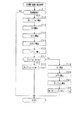
図4に本実施形態における充放電可能電力算出処理をフローチャートとして示す。この充放電可能電力算出処理は、制御装置50によって周期的に実施される。
FIG. 4 is a flowchart showing charge / dischargeable power calculation processing in the present embodiment. This chargeable / dischargeable power calculation process is periodically performed by the
ステップS11において、蓄電池10に対する充電・放電のいずれか一方が開始されるタイミングであるか否かを判定する。
In step S <b> 11, it is determined whether or not it is a timing at which one of charging and discharging of the
充放電の開始タイミングでないと判定された場合(S11:NO)、処理を終了する。充放電の開始タイミングであると判定された場合(S11:YES)、ステップS12において、内部抵抗値算出手段としての制御装置50は、式(8)を用いてTa秒後における抵抗の予測値Rt(Ta)を算出する。
When it is determined that it is not the charge / discharge start timing (S11: NO), the process is terminated. When it is determined that it is the charge / discharge start timing (S11: YES), in step S12, the
次に、ステップS13において、充放電の開始時における蓄電池10の電圧の検出値V(0)と、蓄電池10の目標電圧Vmとの差ΔVを算出する。次に、特定変化量算出手段としての制御装置50は、ステップS14及びS15において、特定変化量としての分極電圧の変化量ΔVc及び開放電圧の変化量ΔOCVを算出する。ステップS14において、式(5)及び(7)を用いて分極電圧の変化量ΔVcを算出する。次に、ステップS15において、充放電開始時からTa秒後までに充電に伴って増加する開放電圧の変化量ΔOCVを算出する。次に、ステップS16において、予測値算出手段としての制御装置50は、式(1)を用いて端子間電圧を目標電圧Vmまで変化させた場合にTa秒後に流れる通電電流の予測値I^(Ta)を算出する。
Next, in step S <b> 13, a difference ΔV between the detected value V (0) of the voltage of the
次に、ステップS17において、Ta秒後に流れる通電電流の予測値I^(Ta)が蓄電池10の目標電流Im以下か否かの判定を行う。端子間電圧Vを目標電圧Vmまで変化させた場合にTa秒後に流れる電流の予測値I^(Ta)が、目標電流Im以下の場合(S17:YES)、ステップS18において、電力算出手段としての制御装置50は、目標電圧Vmと電流の予測値I^(Ta)との積を充放電可能電力W(Ta)として処理を終了する(W(Ta)=Vm・I^(Ta))。
Next, in step S <b> 17, it is determined whether or not the predicted value I ^ (Ta) of the energization current that flows after Ta seconds is equal to or less than the target current Im of the
端子間電圧を目標電圧Vmまで変化させた場合にTa秒後に流れる電流の予測値I(Ta)が、目標電流Imを超える場合(S17:NO)、予測値算出手段としての制御装置50は、ステップS19〜S21の処理において、蓄電池10に目標電流Imを流した場合の蓄電池10の端子間電圧の予測値V^(Ta)を算出する。
When the predicted value I (Ta) of the current that flows after Ta seconds when the terminal voltage is changed to the target voltage Vm exceeds the target current Im (S17: NO), the
ステップS19において、充放電開始時におけるの電流の検出値I(0)と目標電流Imの差ΔIを算出する(ΔI=Im−I(0))。ステップS20において、蓄電池10に流れる電流がΔI変化することに伴う電圧変化の予測値ΔVr^を、ΔIとTa秒後の内部抵抗値R(Ta)との積として算出する(ΔVr^=ΔI・R(Ta))。
In step S19, a difference ΔI between the detected current value I (0) and the target current Im at the start of charge / discharge is calculated (ΔI = Im−I (0)). In step S20, the predicted value ΔVr ^ of the voltage change accompanying the change of the current flowing through the
ステップS21において、充放電の開始時点における蓄電池の端子間電圧の検出値V(0)に、ΔVr^、ΔVc及びΔOCVを加算することで、蓄電池10に目標電流Imを流した場合の蓄電池10の端子間電圧の予測値V^(Ta)を算出する(V^(Ta)=V(0)+ΔVr^+Vc+ΔOCV)。そして、ステップS22において、電力算出手段としての制御装置50は、充放電可能電力W(Ta)を目標電流Imと端子間電圧の予測値V^(Ta)との積として算出し、処理を終了する(W(Ta)=Im・V^(Ta))。
In step S21, by adding ΔVr ^, ΔVc, and ΔOCV to the detected value V (0) of the inter-terminal voltage of the storage battery at the start of charging / discharging, the
以下、本実施形態の奏する効果を述べる。 Hereinafter, the effect which this embodiment show | plays is described.
上記構成では、蓄電池10の充電又は放電を行う場合に、所定期間における端子間電圧Vの変化量ΔVのうち、蓄電池10における電荷の蓄積又は放出に伴う電圧変化分である特定変化量ΔVc及びΔOCVを算出し、その特定変化量ΔVc及びΔOCVを用いて、予測対象値としての通電電流(電流予測値I^(Ta))又は電圧変化量(電圧予測値V^(Ta))を算出するようにした。また、その予測対象値I^(Ta)及びV^(Ta)に基づいて充放電可能な電力を算出するようにした。この場合、蓄電池10における電荷の蓄積又は放出に伴う電圧変化分である特定変化量ΔVc及びΔOCVを考慮して電流予測又は電圧予測を行い、その予測結果に基づいて電力制御を実施できる。その結果、充放電可能な電力を精度良く算出することができる。
In the above configuration, when the
具体的には、蓄電池10の端子間電圧の検出値V(0)と蓄電池10の端子間電圧の目標電圧Vmとの差から、特定変化量を減算することで、蓄電池10の端子間電圧が目標電圧Vmに変化した場合における通電電流の変化に伴う電圧変化量ΔVrを算出する。そして、算出された通電電流の変化に伴う電圧変化量ΔVrを蓄電池10の内部抵抗値Rt(Ta)で除算した値を通電電流の検出値I(0)に加算することで、蓄電池10の端子間電圧Vが目標電圧Vmに変化する場合の通電電流の予測値I^(Ta)を精度よく算出することができる。そして、この通電電流の予測値I^(Ta)を用いることで、充放電電力を精度よく算出することができる。
Specifically, the inter-terminal voltage of the
また、端子間電圧の予測値V^(Ta)を算出する場合、蓄電池10に流れる電流の検出値と、目標電流Imとの差を算出し、その差分だけ電流が変化した場合にその変化に伴って変化する電圧変化の予測値ΔVr^を算出する。そして、その算出された通電電流の変化に伴う電圧変化の予測値ΔVr^、特定変化量ΔVc,ΔOCVに基づいて、端子間電圧の予測値V^(Ta)を算出することで、精度よく端子間電圧の予測値を算出することができ、ひいては、充放電可能電力を精度よく算出することが可能となる。
In addition, when calculating the predicted value V ^ (Ta) of the inter-terminal voltage, the difference between the detected value of the current flowing through the
蓄電池10の等価回路は容量成分を含み、この容量成分においては電荷の蓄積が生じる。そして、蓄電池10に対して電流が流れると、容量成分に蓄積される電荷の量が変化することで、容量成分の分極状態は変化する。この分極状態の変化を考慮して特定変化量としての分極電圧の変化量ΔVcを算出し、その分極電圧の変化量ΔVcを用いて、電圧予測又は電流予測を行う構成とした。これにより、蓄電池10に対して充放電可能な電力を精度よく算出することが可能となる。
The equivalent circuit of the
蓄電池10に対して充放電を行うと、蓄電池10の内部に正電荷又は負電荷が蓄積する。この電荷の蓄積によって、電圧源としての蓄電池10の開放電圧が増加又は減少する。そこで、特定変化量としての開放電圧の変化量ΔOCVを算出し、その開放電圧の変化量ΔOCVを用いて、電圧予測又は電流予測を行う構成とすることで、蓄電池10に対して充放電可能な電力を精度よく算出することが可能となる。
When the
端子間電圧又は通電電流が変化すると、その変化に伴って蓄電池10の内部抵抗Rt(t)が変化する。そこで、蓄電池10の等価回路を構成する回路定数に基づいて、所定時間経過後における蓄電池の内部抵抗を算出する。そして、その算出値Rt(Ta)を用いて、電流予測及び電圧予測を行うことで、精度よく充放電可能電力を算出することが可能となる。
When the inter-terminal voltage or the energization current changes, the internal resistance Rt (t) of the
蓄電池10の端子間電圧Vが目標電圧Vmに変化する場合の通電電流の予測値I^(Ta)が、蓄電池10に流れる通電電流の目標電流Im超えるか否かを判定する。通電電電流の予測値I^(Ta)が通電電流の目標電流Imを超える場合、つまり、通電電流が目標電流Imによって制限される場合に、蓄電池10に目標電流Imが流れる場合の蓄電池10の端子間電圧の予測値V^(Ta)を算出する構成とした。このような構成にすることで、蓄電池10の通電電流を目標電流Imに制限しつつ、充放電電力の算出を行うことが可能になる。
It is determined whether the predicted value I ^ (Ta) of the energization current when the inter-terminal voltage V of the
(他の実施形態)
・上記実施形態では、制御装置50が充放電可能電力及び放電可能電力の双方を算出する構成としたが、これに代えて、充放電可能電力及び放電可能電力のいずれか一方を算出する構成としてもよい。
(Other embodiments)
In the above-described embodiment, the
・上記実施形態では、通電電流の予測値I^(Ta)が目標電流Imを超える場合に、通電電流Iが目標電流Imに変化した場合の端子間電圧の予測値V^(Ta)を算出する構成としたが、これを省略してもよい。また、通電電流の予測値I^(Ta)が目標電流Imと異なる所定の基準電流を超える場合に、通電電流Iが目標電流Imに変化した場合の端子間電圧の予測値V^(Ta)を算出する構成としてもよい。また、通電電流Iが目標電流Imに変化した場合の端子間電圧の予測値V^(Ta)を算出し、その予測値V^(Ta)が目標電圧Vmを超える場合に、端子間電圧Vが目標電圧に変化した場合の通電電流の予測値I^(Ta)を算出する構成としてもよい。 In the above embodiment, when the predicted value I ^ (Ta) of the energized current exceeds the target current Im, the predicted value V ^ (Ta) of the inter-terminal voltage when the energized current I changes to the target current Im is calculated. However, this may be omitted. Further, when the predicted value I ^ (Ta) of the energized current exceeds a predetermined reference current different from the target current Im, the predicted value V ^ (Ta) of the inter-terminal voltage when the energized current I changes to the target current Im. It is good also as a structure which calculates. Further, a predicted value V ^ (Ta) of the inter-terminal voltage when the energization current I changes to the target current Im is calculated, and when the predicted value V ^ (Ta) exceeds the target voltage Vm, the terminal voltage V It is good also as a structure which calculates the predicted value I ^ (Ta) of the energization current when changes to the target voltage.
・特定変化量として、分極電圧の変化量ΔVc及び開放電圧の変化量ΔOCVの和を用いる構成としたが、これに代えて、特定変化量として、分極電圧の変化量ΔVc及び開放電圧の変化量ΔOCVのいずれか一方を用いる構成としてもよい。 Although the sum of the change amount ΔVc of the polarization voltage and the change amount ΔOCV of the open circuit voltage is used as the specific change amount, the change amount ΔVc of the polarization voltage and the change amount of the open circuit voltage are used as the specific change amount instead. It is good also as a structure using any one of (DELTA) OCV.
・蓄電池10の内部抵抗11の値を時間変化するものとして扱ったが、これに代えて、蓄電池10の内部抵抗11の値を時間変化しない一定値としてもよい。
-Although the value of the
・上記実施形態では、充放電の開始時に充放電可能電力を算出する構成としたが、これを変更してもよい。例えば、充放電の実施時において、所定期間毎に充放電可能電力を算出する構成としてもよい。 In the above embodiment, the chargeable / dischargeable power is calculated at the start of charging / discharging, but this may be changed. For example, it is good also as a structure which calculates charge / dischargeable electric power for every predetermined period at the time of implementation of charging / discharging.
・蓄電池10の内部抵抗11を直流抵抗と2つの反応抵抗の直列接続体とするモデルを用いて表したが、これを代えてもよい。例えば、1の直流抵抗と1つの反応抵抗の直列接続体としてもよいし、直列抵抗を含まない反応抵抗の直列接続体としてもよい。
-Although represented using the model which used the
・目標電圧Vm、及び、目標電流Imを蓄電池10が過充電及び過放電とならないような値に設定したが、これを変更してもよい。例えば、電気負荷20の駆動電圧や、インバータ21の直流交流変換性能などに基づいて設定してもよい。
Although the target voltage Vm and the target current Im are set to values that prevent the
・蓄電池10をリチウムイオン蓄電池としたが、これに代えて、鉛蓄電池やニッケル水素蓄電池を用いてもよい。
-Although the
10…蓄電池、50…制御装置。 10 ... storage battery, 50 ... control device.
Claims (7)
前記蓄電池の充電又は放電を行う場合に、前記所定期間における前記端子間電圧の変化量のうち、前記蓄電池の内部における電荷の蓄積に起因する電圧変化分である特定変化量を算出する特定変化量算出手段と、
前記所定期間の経過後に前記端子間電圧を所定電圧まで変化させるのに要する前記蓄電池に流れる通電電流と、前記所定期間において所定電流を流した場合に前記所定期間の経過後における前記蓄電池の端子間電圧とのいずれかを予測対象値とし、前記特定変化量算出手段により算出した特定変化量を用いて、前記予測対象値を算出する予測値算出手段と、
前記予測値算出手段により算出した予測対象値に基づいて、前記充放電可能な電力を算出する電力算出手段と、
を備えることを特徴とする電池制御装置。 When the storage battery (10) is charged or discharged by supplying a current for a predetermined period, and the voltage between the terminals of the storage battery changes due to the charging or discharging, the chargeable / dischargeable power after the lapse of the predetermined period is calculated. A battery control device (50) comprising:
A specific change amount that calculates a specific change amount that is a voltage change amount due to charge accumulation inside the storage battery among the change amount of the inter-terminal voltage during the predetermined period when the storage battery is charged or discharged. A calculation means;
An energizing current flowing through the storage battery required to change the inter-terminal voltage to a predetermined voltage after the predetermined period has elapsed, and between the terminals of the storage battery after the predetermined period when a predetermined current is passed during the predetermined period A prediction value calculation unit that calculates the prediction target value using the specific change amount calculated by the specific change amount calculation unit, with any of the voltage as a prediction target value;
Power calculating means for calculating the chargeable / dischargeable power based on the prediction target value calculated by the predicted value calculating means;
A battery control device comprising:
前記特定変化量算出手段は、前記等価回路の容量成分の分極状態の変化に基づいて、前記特定変化量を算出することを特徴とする請求項1に記載の電池制御装置。 The equivalent circuit of the storage battery includes capacity components (C1, C2),
The battery control device according to claim 1, wherein the specific change amount calculating unit calculates the specific change amount based on a change in a polarization state of a capacitance component of the equivalent circuit.
前記所定期間の開始時における前記端子間電圧の検出値と、前記所定期間の経過後の前記端子間電圧の目標値と、の差である変化電圧を算出する変化電圧算出手段と、を備え、
前記予測値算出手段は、前記変化電圧に対して前記特定変化量算出手段により算出された特定変化量を減算又は加算して求められた電圧値と、前記蓄電池の内部抵抗値と、前記通電電流の検出値とに基づいて、前記予測対象値としての前記通電電流の予測値を算出する電流予測値算出手段を備えることを特徴とする請求項1乃至3のいずれか1項に記載の電池制御装置。 Detection value acquisition means for acquiring detection values from a voltage detection means (40) for detecting a voltage between terminals of the storage battery and a current detection means (30) for detecting an energization current flowing through the storage battery;
Change voltage calculation means for calculating a change voltage that is a difference between a detected value of the voltage between the terminals at the start of the predetermined period and a target value of the voltage between the terminals after the predetermined period has elapsed,
The predicted value calculation means includes a voltage value obtained by subtracting or adding the specific change amount calculated by the specific change amount calculation means to the change voltage, an internal resistance value of the storage battery, and the energization current. 4. The battery control according to claim 1, further comprising a current predicted value calculation unit that calculates a predicted value of the energization current as the prediction target value based on the detected value of the current value. 5. apparatus.
前記所定期間の開始時における前記通電電流の検出値と、前記通電電流の目標値と、の差である変化電流を算出する変化電流算出手段と、を備え、
前記予測値算出手段は、前記通電電流の予測値が前記基準値を超えていると前記判定手段によって判定された場合に、前記変化電流と前記蓄電池の内部抵抗値とを積算することで求められる、前記蓄電池の内部抵抗に流れる通電電流が変化することで生じる電圧変化分と、前記特定変化量算出手段により算出された特定変化量と、前記端子間電圧の検出値とを減算又は加算して、前記予測対象値としての前記端子間電圧の予測値を算出する電圧予測値算出手段を備えることを特徴とする請求項4に記載の電池制御装置。 Determining means for determining whether or not the predicted value of the energization current calculated by the predicted current value calculating means exceeds a predetermined reference value;
Change current calculation means for calculating a change current that is a difference between a detected value of the energization current at the start of the predetermined period and a target value of the energization current; and
The predicted value calculation means is obtained by integrating the change current and the internal resistance value of the storage battery when the determination means determines that the predicted value of the energization current exceeds the reference value. Subtracting or adding the voltage change caused by the change in the energizing current flowing through the internal resistance of the storage battery, the specific change calculated by the specific change calculating means, and the detected value of the voltage between the terminals. The battery control device according to claim 4, further comprising: a predicted voltage value calculation unit that calculates a predicted value of the inter-terminal voltage as the prediction target value.
前記所定期間の開始時における前記通電電流の検出値と、前記所定期間の経過後の前記通電電流の目標値と、の差である変化電流を算出する変化電流算出手段と、を備え、
前記予測値算出手段は、前記変化電流と前記蓄電池の内部抵抗値とを積算することで求められる、前記蓄電池の内部抵抗に流れる通電電流が変化することで生じる電圧変化分と、前記特定変化量算出手段により算出された特定変化量と、前記端子間電圧の検出値とを減算又は加算して、前記予測対象値としての前記端子間電圧の予測値を算出する電圧予測値算出手段を備えることを特徴とする請求項1乃至3のいずれか1項に記載の電池制御装置。 Detection value acquisition means for acquiring detection values from a voltage detection means (40) for detecting a voltage between terminals of the storage battery and a current detection means (30) for detecting an energization current flowing through the storage battery;
Change current calculation means for calculating a change current that is a difference between a detection value of the energization current at the start of the predetermined period and a target value of the energization current after the elapse of the predetermined period;
The predicted value calculation means is obtained by integrating the change current and the internal resistance value of the storage battery, and a voltage change caused by a change in energization current flowing through the internal resistance of the storage battery, and the specific change amount A predicted voltage value calculating unit that calculates a predicted value of the inter-terminal voltage as the prediction target value by subtracting or adding the specific change amount calculated by the calculating unit and the detected value of the inter-terminal voltage; The battery control device according to any one of claims 1 to 3.
前記予測値算出手段は、前記内部抵抗値算出手段によって算出された前記所定期間の経過後の前記蓄電池の内部抵抗値を用いて、前記予測対象値を算出することを特徴とする請求項4乃至6のいずれか1項に記載の電池制御装置。 The internal resistance value of the storage battery that changes with the change of the inter-terminal voltage or the energization current in the predetermined period, and the circuit constants (Rs, R1, R2, C1, C2) that constitute the equivalent circuit of the storage battery An internal resistance value calculating means for calculating based on time,
5. The prediction value calculation unit calculates the prediction target value by using the internal resistance value of the storage battery after the predetermined period calculated by the internal resistance value calculation unit. The battery control device according to any one of 6.
Priority Applications (3)
| Application Number | Priority Date | Filing Date | Title |
|---|---|---|---|
| JP2013254548A JP5929880B2 (en) | 2013-12-09 | 2013-12-09 | Battery control device |
| DE102014116424.5A DE102014116424B4 (en) | 2013-12-09 | 2014-11-11 | Battery control device |
| US14/563,032 US9618584B2 (en) | 2013-12-09 | 2014-12-08 | Battery control device |
Applications Claiming Priority (1)
| Application Number | Priority Date | Filing Date | Title |
|---|---|---|---|
| JP2013254548A JP5929880B2 (en) | 2013-12-09 | 2013-12-09 | Battery control device |
Publications (2)
| Publication Number | Publication Date |
|---|---|
| JP2015114135A true JP2015114135A (en) | 2015-06-22 |
| JP5929880B2 JP5929880B2 (en) | 2016-06-08 |
Family
ID=53185404
Family Applications (1)
| Application Number | Title | Priority Date | Filing Date |
|---|---|---|---|
| JP2013254548A Active JP5929880B2 (en) | 2013-12-09 | 2013-12-09 | Battery control device |
Country Status (3)
| Country | Link |
|---|---|
| US (1) | US9618584B2 (en) |
| JP (1) | JP5929880B2 (en) |
| DE (1) | DE102014116424B4 (en) |
Cited By (7)
| Publication number | Priority date | Publication date | Assignee | Title |
|---|---|---|---|---|
| WO2018047258A1 (en) * | 2016-09-07 | 2018-03-15 | 日立化成株式会社 | Simulation method and simulation device |
| JP2018041622A (en) * | 2016-09-07 | 2018-03-15 | 日立化成株式会社 | Simulation method and simulation apparatus |
| JP2018186101A (en) * | 2015-07-02 | 2018-11-22 | 日立オートモティブシステムズ株式会社 | Battery control device and battery pack |
| WO2022244391A1 (en) * | 2021-05-18 | 2022-11-24 | 株式会社Gsユアサ | Determination method, determination device, and program |
| WO2023139973A1 (en) * | 2022-01-18 | 2023-07-27 | 株式会社Gsユアサ | Estimation device, power storage device, estimation method, and program |
| WO2024154520A1 (en) * | 2023-01-19 | 2024-07-25 | 株式会社Gsユアサ | Estimation method, estimation program, estimation device, and power storage device |
| WO2024257748A1 (en) * | 2023-06-15 | 2024-12-19 | 株式会社Gsユアサ | Prediction device, power storage device, prediction method, and prediction program |
Families Citing this family (4)
| Publication number | Priority date | Publication date | Assignee | Title |
|---|---|---|---|---|
| JP6588632B2 (en) * | 2016-05-18 | 2019-10-09 | 日立オートモティブシステムズ株式会社 | Battery control device |
| CN111934369B (en) * | 2019-05-13 | 2022-09-06 | Oppo广东移动通信有限公司 | Charging method and device, equipment, storage medium |
| JP7540403B2 (en) | 2021-06-29 | 2024-08-27 | 株式会社デンソー | Battery measurement device and battery measurement method |
| JP7775720B2 (en) * | 2022-01-20 | 2025-11-26 | 株式会社デンソー | Secondary Battery System |
Citations (9)
| Publication number | Priority date | Publication date | Assignee | Title |
|---|---|---|---|---|
| JP2003303627A (en) * | 2002-04-10 | 2003-10-24 | Hitachi Ltd | Status detecting device and various devices using the same |
| US20070159137A1 (en) * | 2003-02-18 | 2007-07-12 | Gm Global Technology Operations, Inc. | Method and apparatus for generalized recursive least-squares process for battery state of charge and state of health |
| JP2009512845A (en) * | 2005-10-21 | 2009-03-26 | ローベルト ボツシユ ゲゼルシヤフト ミツト ベシユレンクテル ハフツング | Method for predicting the power capacity of an electrical energy accumulator |
| JP2010169609A (en) * | 2009-01-26 | 2010-08-05 | Calsonic Kansei Corp | Battery system and i/o electric power estimation method |
| JP2010203935A (en) * | 2009-03-04 | 2010-09-16 | Nissan Motor Co Ltd | Device of estimating inputtable/outputtable power of secondary battery |
| US20110224928A1 (en) * | 2010-03-10 | 2011-09-15 | Gm Global Technology Operations, Inc. | Battery state estimator using multiple sampling rates |
| US20120179435A1 (en) * | 2011-01-10 | 2012-07-12 | Ford Global Technologies, Llc | Method For Determining A Power Capability For A Battery |
| JP2013507628A (en) * | 2009-10-16 | 2013-03-04 | バイエリッシェ モートーレン ウエルケ アクチエンゲゼルシャフト | Method for determining and / or predicting the maximum possible output of a battery |
| JP2013205021A (en) * | 2012-03-27 | 2013-10-07 | Denso Corp | Device for calculating equivalent amount of charging of secondary battery |
Family Cites Families (4)
| Publication number | Priority date | Publication date | Assignee | Title |
|---|---|---|---|---|
| JPH117984A (en) * | 1997-06-13 | 1999-01-12 | Sony Corp | Rechargeable battery capacity detection method |
| US6850038B2 (en) * | 2002-05-14 | 2005-02-01 | Yazaki Corporation | Method of estimating state of charge and open circuit voltage of battery, and method and device for computing degradation degree of battery |
| JP2007121030A (en) | 2005-10-26 | 2007-05-17 | Denso Corp | Device for detecting internal state of power storage device for vehicle |
| JP4375458B2 (en) | 2007-08-01 | 2009-12-02 | 株式会社デンソー | Secondary battery charge state estimation device and charge control system |
-
2013
- 2013-12-09 JP JP2013254548A patent/JP5929880B2/en active Active
-
2014
- 2014-11-11 DE DE102014116424.5A patent/DE102014116424B4/en active Active
- 2014-12-08 US US14/563,032 patent/US9618584B2/en active Active
Patent Citations (9)
| Publication number | Priority date | Publication date | Assignee | Title |
|---|---|---|---|---|
| JP2003303627A (en) * | 2002-04-10 | 2003-10-24 | Hitachi Ltd | Status detecting device and various devices using the same |
| US20070159137A1 (en) * | 2003-02-18 | 2007-07-12 | Gm Global Technology Operations, Inc. | Method and apparatus for generalized recursive least-squares process for battery state of charge and state of health |
| JP2009512845A (en) * | 2005-10-21 | 2009-03-26 | ローベルト ボツシユ ゲゼルシヤフト ミツト ベシユレンクテル ハフツング | Method for predicting the power capacity of an electrical energy accumulator |
| JP2010169609A (en) * | 2009-01-26 | 2010-08-05 | Calsonic Kansei Corp | Battery system and i/o electric power estimation method |
| JP2010203935A (en) * | 2009-03-04 | 2010-09-16 | Nissan Motor Co Ltd | Device of estimating inputtable/outputtable power of secondary battery |
| JP2013507628A (en) * | 2009-10-16 | 2013-03-04 | バイエリッシェ モートーレン ウエルケ アクチエンゲゼルシャフト | Method for determining and / or predicting the maximum possible output of a battery |
| US20110224928A1 (en) * | 2010-03-10 | 2011-09-15 | Gm Global Technology Operations, Inc. | Battery state estimator using multiple sampling rates |
| US20120179435A1 (en) * | 2011-01-10 | 2012-07-12 | Ford Global Technologies, Llc | Method For Determining A Power Capability For A Battery |
| JP2013205021A (en) * | 2012-03-27 | 2013-10-07 | Denso Corp | Device for calculating equivalent amount of charging of secondary battery |
Cited By (14)
| Publication number | Priority date | Publication date | Assignee | Title |
|---|---|---|---|---|
| JP2018186101A (en) * | 2015-07-02 | 2018-11-22 | 日立オートモティブシステムズ株式会社 | Battery control device and battery pack |
| US10680453B2 (en) | 2015-07-02 | 2020-06-09 | Hitachi Automotive Systems, Ltd. | Battery control device |
| US11247581B2 (en) | 2015-07-02 | 2022-02-15 | Vehicle Energy Japan, Inc. | Battery control device |
| WO2018047258A1 (en) * | 2016-09-07 | 2018-03-15 | 日立化成株式会社 | Simulation method and simulation device |
| JP2018041622A (en) * | 2016-09-07 | 2018-03-15 | 日立化成株式会社 | Simulation method and simulation apparatus |
| JPWO2018047258A1 (en) * | 2016-09-07 | 2019-06-24 | 日立化成株式会社 | Simulation method and simulation apparatus |
| WO2022244391A1 (en) * | 2021-05-18 | 2022-11-24 | 株式会社Gsユアサ | Determination method, determination device, and program |
| JP2022177666A (en) * | 2021-05-18 | 2022-12-01 | 株式会社Gsユアサ | Determination method, determination device, and program |
| DE112022002645T5 (en) | 2021-05-18 | 2024-02-29 | Gs Yuasa International Ltd. | Determination method, determination device and program |
| US12422489B2 (en) | 2021-05-18 | 2025-09-23 | Gs Yuasa International Ltd. | Determination method, determination device, and program |
| WO2023139973A1 (en) * | 2022-01-18 | 2023-07-27 | 株式会社Gsユアサ | Estimation device, power storage device, estimation method, and program |
| DE112022006426T5 (en) | 2022-01-18 | 2024-10-31 | Gs Yuasa International Ltd. | estimation device, energy storage device, estimation method and program |
| WO2024154520A1 (en) * | 2023-01-19 | 2024-07-25 | 株式会社Gsユアサ | Estimation method, estimation program, estimation device, and power storage device |
| WO2024257748A1 (en) * | 2023-06-15 | 2024-12-19 | 株式会社Gsユアサ | Prediction device, power storage device, prediction method, and prediction program |
Also Published As
| Publication number | Publication date |
|---|---|
| DE102014116424A1 (en) | 2015-06-11 |
| US20150160301A1 (en) | 2015-06-11 |
| US9618584B2 (en) | 2017-04-11 |
| DE102014116424B4 (en) | 2024-03-07 |
| JP5929880B2 (en) | 2016-06-08 |
Similar Documents
| Publication | Publication Date | Title |
|---|---|---|
| JP5929880B2 (en) | Battery control device | |
| JP6823162B2 (en) | Battery management device and method for calibrating the charge status of the battery | |
| US10408887B2 (en) | Method for estimating degradation of rechargeable battery, degradation estimation circuit, electronic apparatus and vehicle including same | |
| JP5393837B2 (en) | Battery charge rate estimation device | |
| CN109313239B (en) | Management device and power storage system | |
| JP5897701B2 (en) | Battery state estimation device | |
| JP6672743B2 (en) | Full charge capacity calculation device, computer program, and full charge capacity calculation method | |
| JP6200359B2 (en) | Secondary battery internal temperature estimation device and secondary battery internal temperature estimation method | |
| US20150222132A1 (en) | Storage battery management device, and storage battery management method | |
| CN110914696A (en) | Method and system for estimating battery open cell voltage, state of charge, and state of health during operation of a battery | |
| JP6534746B2 (en) | Battery control device and battery system | |
| CN106030326A (en) | secondary battery system | |
| JP6499075B2 (en) | Secondary battery state detection device and secondary battery state detection method | |
| CN104977544A (en) | Method and apparatus for evaluating residual available energy of battery of battery electric vehicle | |
| CN114080331A (en) | Management device and power supply system | |
| JP6183336B2 (en) | Charge rate calculation device | |
| JP6575308B2 (en) | Internal resistance calculation device, computer program, and internal resistance calculation method | |
| JPWO2017110578A1 (en) | Current monitoring circuit, coulomb counter circuit, battery management system using them, and automobile | |
| JP2014068468A (en) | Charge control device | |
| JP5832380B2 (en) | Apparatus for estimating cell state of battery pack | |
| JP2013108919A (en) | Soc estimator | |
| JP7172014B2 (en) | Device and method for estimating state of charge | |
| JP2015215272A (en) | Secondary battery state detection device and secondary battery state detection method | |
| JP2015206758A (en) | Device for estimating parameter of equivalent circuit of secondary battery for vehicle | |
| JP6868976B2 (en) | Deterioration estimation method for rechargeable batteries, deterioration estimation circuit, and electronic devices and automobiles using it |
Legal Events
| Date | Code | Title | Description |
|---|---|---|---|
| A621 | Written request for application examination |
Free format text: JAPANESE INTERMEDIATE CODE: A621 Effective date: 20150522 |
|
| A977 | Report on retrieval |
Free format text: JAPANESE INTERMEDIATE CODE: A971007 Effective date: 20151015 |
|
| A131 | Notification of reasons for refusal |
Free format text: JAPANESE INTERMEDIATE CODE: A131 Effective date: 20151027 |
|
| A521 | Request for written amendment filed |
Free format text: JAPANESE INTERMEDIATE CODE: A523 Effective date: 20151224 |
|
| A131 | Notification of reasons for refusal |
Free format text: JAPANESE INTERMEDIATE CODE: A131 Effective date: 20160119 |
|
| A521 | Request for written amendment filed |
Free format text: JAPANESE INTERMEDIATE CODE: A523 Effective date: 20160315 |
|
| TRDD | Decision of grant or rejection written | ||
| A01 | Written decision to grant a patent or to grant a registration (utility model) |
Free format text: JAPANESE INTERMEDIATE CODE: A01 Effective date: 20160405 |
|
| A61 | First payment of annual fees (during grant procedure) |
Free format text: JAPANESE INTERMEDIATE CODE: A61 Effective date: 20160418 |
|
| R151 | Written notification of patent or utility model registration |
Ref document number: 5929880 Country of ref document: JP Free format text: JAPANESE INTERMEDIATE CODE: R151 |
|
| R250 | Receipt of annual fees |
Free format text: JAPANESE INTERMEDIATE CODE: R250 |
|
| R250 | Receipt of annual fees |
Free format text: JAPANESE INTERMEDIATE CODE: R250 |
|
| R250 | Receipt of annual fees |
Free format text: JAPANESE INTERMEDIATE CODE: R250 |
|
| R250 | Receipt of annual fees |
Free format text: JAPANESE INTERMEDIATE CODE: R250 |
|
| R250 | Receipt of annual fees |
Free format text: JAPANESE INTERMEDIATE CODE: R250 |
|
| R250 | Receipt of annual fees |
Free format text: JAPANESE INTERMEDIATE CODE: R250 |
|
| R250 | Receipt of annual fees |
Free format text: JAPANESE INTERMEDIATE CODE: R250 |