JP2015114115A - Weigh scale and weight measuring method - Google Patents

Weigh scale and weight measuring method Download PDF

Info

Publication number
JP2015114115A
JP2015114115A JP2013254028A JP2013254028A JP2015114115A JP 2015114115 A JP2015114115 A JP 2015114115A JP 2013254028 A JP2013254028 A JP 2013254028A JP 2013254028 A JP2013254028 A JP 2013254028A JP 2015114115 A JP2015114115 A JP 2015114115A
Authority
JP
Japan
Prior art keywords
weight
scale
weighing scale
main body
load
Prior art date
Legal status (The legal status is an assumption and is not a legal conclusion. Google has not performed a legal analysis and makes no representation as to the accuracy of the status listed.)
Pending
Application number
JP2013254028A
Other languages
Japanese (ja)
Inventor
貴志 熊谷
Takashi Kumagai
貴志 熊谷
Current Assignee (The listed assignees may be inaccurate. Google has not performed a legal analysis and makes no representation or warranty as to the accuracy of the list.)
Tanita Corp
Original Assignee
Tanita Corp
Priority date (The priority date is an assumption and is not a legal conclusion. Google has not performed a legal analysis and makes no representation as to the accuracy of the date listed.)
Filing date
Publication date
Application filed by Tanita Corp filed Critical Tanita Corp
Priority to JP2013254028A priority Critical patent/JP2015114115A/en
Publication of JP2015114115A publication Critical patent/JP2015114115A/en
Pending legal-status Critical Current

Links

Images

Landscapes

  • Force Measurement Appropriate To Specific Purposes (AREA)

Abstract

【課題】底面に重量がかかっている状態であっても正確に測定対象の重量を測定することができる重量計および重量測定方法を提供する。【解決手段】本体と、荷重に応じた重量を測定する第1重量測定部と、本体の底面にかかる重量を測定する第2重量測定部と、第2重量測定部による測定結果を用いて、第1重量測定部による測定結果を補正する補正処理部とを備える重量計である。【選択図】図8Provided are a weigh scale and a weight measuring method capable of accurately measuring the weight of an object to be measured even when the weight is applied to the bottom surface. Using a measurement result of a main body, a first weight measuring unit for measuring a weight according to a load, a second weight measuring unit for measuring a weight applied to a bottom surface of the main body, and a second weight measuring unit, It is a weigh scale provided with the correction process part which correct | amends the measurement result by a 1st weight measurement part. [Selection] Figure 8

Description

本発明は、重量計および重量測定方法に関する。   The present invention relates to a weighing scale and a weight measuring method.

重量計におけるエラー状態のひとつに、「ボトミング」と呼ばれる状態がある。ボトミングは、荷重による負荷が加えられた場合に、重量計の本体の底面が床面などと接触する現象である。この現象は、例えば、重量計の一種である体重計の場合には、絨毯や畳などの柔軟な床面、又は平らでない床面に重量計を設置して体重を測定したときに発生しやすい。このボトミングが発生すると、重量計の底面に床からの反力が生じて重量計の底面に重量がかかるので、測定対象の重量は実際の重量よりも少なく測定されてしまう。そこで、このボトミングに対処するための技術として、重量計の底面と床面などとの距離を測定することによりボトミングの発生を検出する重量計が提案させている(特許文献1)。   One of the error states in the weigh scale is a state called “bottoming”. Bottoming is a phenomenon in which the bottom surface of the main body of the weighing scale comes into contact with the floor surface or the like when a load due to a load is applied. For example, in the case of a weight scale that is a kind of weight scale, this phenomenon is likely to occur when a weight scale is installed on a flexible floor surface such as a carpet or a tatami mat or an uneven floor surface and the weight is measured. . When this bottoming occurs, a reaction force from the floor is generated on the bottom surface of the weigh scale and the bottom surface of the weigh scale is weighted, so that the weight of the object to be measured is measured smaller than the actual weight. Therefore, as a technique for coping with this bottoming, a weight scale that detects the occurrence of bottoming by measuring the distance between the bottom surface of the weight scale and the floor surface has been proposed (Patent Document 1).

特開2010−25596号公報JP 2010-25596 A

しかし、特許文献1に記載の発明は、ボトミングの発生を検出するものであり、ボトミングが発生している場合における重量計の測定結果をどうするかという未解決の問題がある。   However, the invention described in Patent Document 1 detects the occurrence of bottoming, and there is an unsolved problem of what to do with the measurement result of the weighing scale when bottoming has occurred.

本発明はこのような問題点に鑑みなされたものであり、ボトミングが発生している状態であっても、正確に測定対象の重量を測定することができる重量計および重量測定方法を提供することを目的とする。   The present invention has been made in view of such problems, and provides a weight scale and a weight measurement method capable of accurately measuring the weight of a measurement object even when bottoming is occurring. With the goal.

上述した課題を解決するために、本発明は、本体と、荷重に応じた重量を測定する第1重量測定部と、本体の底面にかかる重量を測定する第2重量測定部と、第2重量測定部による測定結果を用いて、第1重量測定部による測定結果を補正する補正処理部とを備える重量計である。   In order to solve the above-described problems, the present invention includes a main body, a first weight measuring unit that measures a weight according to a load, a second weight measuring unit that measures a weight applied to the bottom surface of the main body, and a second weight. The weighing scale includes a correction processing unit that corrects the measurement result obtained by the first weight measurement unit using the measurement result obtained by the measurement unit.

また、本発明は、荷重に応じた重量を測定し、本体の底面にかかる重量を測定し、本体の底面にかかる重量の測定結果を用いて、荷重に応じた重量の測定結果を補正する重量測定方法である。   Further, the present invention measures the weight according to the load, measures the weight applied to the bottom surface of the main body, and uses the measurement result of the weight applied to the bottom surface of the main body to correct the measurement result of the weight according to the load. This is a measurement method.

本発明によれば、ボトミングが発生している状態、すなわち、重量計の底面に重量がかかっている状態であっても、正確に測定対象の重量を測定することができる。なお、ここに記載された効果は必ずしも限定されるものではなく、明細書中に記載されたいずれかの効果であってもよい。   According to the present invention, it is possible to accurately measure the weight of an object to be measured even in a state where bottoming is occurring, that is, a state where a weight is applied to the bottom surface of the weighing scale. In addition, the effect described here is not necessarily limited, and may be any effect described in the specification.

図1は、重量計の底面と絨毯との接触によるボトミングの発生の態様の例を示す図である。図1Aは、絨毯の上に設置された重量計が無負荷状態である場合を示す図であり、図1Bは、絨毯の上に設置された重量計が負荷状態である場合を示す図である。FIG. 1 is a diagram showing an example of an aspect of bottoming caused by contact between a bottom surface of a weight scale and a carpet. FIG. 1A is a diagram illustrating a case where the weight scale installed on the carpet is in an unloaded state, and FIG. 1B is a diagram illustrating a case in which the weight scale installed on the carpet is in a loaded state. . 図2は、重量計の底面と畳との接触によるボトミングの発生の態様の例を示す図である。図2Aは、畳の上に設置された重量計が無負荷状態である場合を示す図であり、図2Bは、畳の上に設置された重量計が負荷状態である場合を示す図である。FIG. 2 is a diagram illustrating an example of a mode of occurrence of bottoming due to contact between the bottom surface of the weight scale and the tatami mat. FIG. 2A is a diagram illustrating a case where the weight scale installed on the tatami is in an unloaded state, and FIG. 2B is a diagram illustrating a case in which the weight scale installed on the tatami is in a loaded state. . 図3は、重量計の底面と平坦でない床面との接触によるボトミングの発生の態様の例を示す図である。図3Aは、平坦でない床面の上に設置された重量計が無負荷状態である場合を示す図であり、図3Bは、平坦でない床面の上に設置された重量計が負荷状態である場合を示す図である。FIG. 3 is a diagram illustrating an example of an aspect of bottoming occurring due to contact between the bottom surface of the weighing scale and the non-flat floor surface. FIG. 3A is a diagram illustrating a case where a weight scale installed on a non-flat floor surface is in an unloaded state, and FIG. 3B is a diagram in which a weight scale installed on a non-flat floor surface is in a loaded state. It is a figure which shows a case. 図4は、重量計の底面と平坦で硬い床面との接触によるボトミングの発生の態様の例を示す図である。図4Aは、平坦で硬い床面の上に設置された重量計が無負荷状態である場合を示す図であり、図4Bは、平坦で硬い床面の上に設置された重量計が負荷状態である場合を示す図である。FIG. 4 is a diagram illustrating an example of an aspect of bottoming caused by contact between the bottom surface of the weighing scale and the flat and hard floor surface. FIG. 4A is a diagram showing a case where a weight scale installed on a flat and hard floor surface is in an unloaded state, and FIG. 4B is a diagram showing a state in which the weight scale installed on a flat and hard floor surface is in a loaded state. It is a figure which shows the case where it is. 図5は、本発明の第1の実施の形態に係る重量計の構成を示す図である。図5Aは、重量計の平面図であり、図5Bは、重量計の正面図である。FIG. 5 is a diagram showing the configuration of the weighing scale according to the first embodiment of the present invention. FIG. 5A is a plan view of the weighing scale, and FIG. 5B is a front view of the weighing scale. 図6は、重量計の構成を示すブロック図である。FIG. 6 is a block diagram showing the configuration of the weighing scale. 図7は、第1の実施の形態に係る重量計の構成を示す図である。図7Aは、重量計の底面図であり、図7Bは、無負荷状態の重量計を示す正面図であり、図7Cは、負荷により重量計が撓んでいる状態を示す正面図である。FIG. 7 is a diagram illustrating the configuration of the weighing scale according to the first embodiment. FIG. 7A is a bottom view of the weighing scale, FIG. 7B is a front view showing the weighing scale in an unloaded state, and FIG. 7C is a front view showing a state in which the weighing scale is bent by the load. 図8は、重量計により行われる重量測定処理の流れを示すフローチャートである。FIG. 8 is a flowchart showing the flow of the weight measurement process performed by the weigh scale. 図9は、本発明の第2の実施の形態に係る重量計の分解斜視図である。FIG. 9 is an exploded perspective view of the weigh scale according to the second embodiment of the present invention. 図10は、第2の実施の形態に係る重量計の構成を示す図である。図10Aは、重量計の平面図であり、図10Bは、重量計の正面図である。FIG. 10 is a diagram illustrating a configuration of a weighing scale according to the second embodiment. FIG. 10A is a plan view of the weighing scale, and FIG. 10B is a front view of the weighing scale. 図11は、第2の実施の形態に係る重量計の構成を示す図である。図11Aは、無負荷状態の重量計を示す、図10AにおけるXI−XI断面図であり、図11Bは、負荷により重量計が撓んでいる状態を示す、図10AにおけるXI−XI断面図である。FIG. 11 is a diagram illustrating a configuration of a weighing scale according to the second embodiment. 11A is a cross-sectional view taken along the line XI-XI in FIG. 10A showing the weight scale in an unloaded state, and FIG. 11B is a cross-sectional view taken along the line XI-XI in FIG. 10A showing a state where the weight scale is bent due to the load. . 図12は、本発明の第3の実施の形態に係る重量計の構成を示す図である。図12Aは、重量計の底面図であり、図12Bは、無負荷状態の重量計を示す正面図であり、図12Cは、負荷により重量計が撓んでいる状態を示す正面図である。FIG. 12 is a diagram showing a configuration of a weighing scale according to the third embodiment of the present invention. 12A is a bottom view of the weighing scale, FIG. 12B is a front view showing the weighing scale in an unloaded state, and FIG. 12C is a front view showing a state in which the weighing scale is bent by the load.

以下、本発明の実施の形態について図面を参照しながら説明する。ただし、本発明は以下の実施例のみに限定されるものではない。なお、説明は以下の順序で行う。
<1.ボトミングについて>
<2.第1の実施の形態>
<3.第2の実施の形態>
<4.第3の実施の形態>
<5.変形例>
Hereinafter, embodiments of the present invention will be described with reference to the drawings. However, the present invention is not limited only to the following examples. The description will be given in the following order.
<1. About bottoming>
<2. First Embodiment>
<3. Second Embodiment>
<4. Third Embodiment>
<5. Modification>

<1.ボトミングについて>
まず、本発明の説明の前に、重量計の使用におけるボトミングの発生について説明する。ボトミングが発生すると重量計の底面に重量がかかり、測定対象の重量が実際の重量よりも少なく測定されてしまう。すなわち、重量の正確な測定が不可能となる。
<1. About bottoming>
First, before the description of the present invention, the occurrence of bottoming in the use of a weighing scale will be described. When bottoming occurs, a weight is applied to the bottom surface of the weighing scale, and the weight of the object to be measured is measured less than the actual weight. That is, it is impossible to accurately measure the weight.

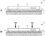
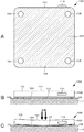
図1乃至図4を参照して、ボトミングの具体例について説明する。図1乃至図4は、重量計の正面図である。なお、図1乃至図4における重量計10は、いずれも重量計本体11を複数の脚部13が支持する構成になっている。重量計10は、例えば、被測定者が上から乗ることにより体重を測定することが可能な体重計である。   A specific example of bottoming will be described with reference to FIGS. 1 to 4 are front views of the weighing scale. 1 to 4 is configured so that the weight main body 11 is supported by a plurality of legs 13. The weight scale 10 is, for example, a weight scale that can measure the weight of the person to be measured who rides from above.

図1は、重量計10が毛足が長い絨毯Cの上に設置されている例である。なお、絨毯Cは、床面F上に敷かれているものである。この例では、図1Aに示されるように、荷重による負荷がない場合には、重量計10の脚部13は絨毯Cの毛の上に載っており、重量計10の底面12は絨毯Cに接触していない。しかし、図1Bに示されるように、重量計10の所定の位置に荷重による負荷が加えられると、重量計10の脚部13が絨毯Cの毛足に沈み込み、重量計10の底面12と絨毯Cの毛足が接触し、ボトミングが発生する場合がある。   FIG. 1 is an example in which the weight scale 10 is installed on a carpet C having long hairs. The carpet C is laid on the floor surface F. In this example, as shown in FIG. 1A, when there is no load due to the load, the leg portion 13 of the weighing scale 10 is placed on the hair of the carpet C, and the bottom surface 12 of the weighing scale 10 is placed on the carpet C. There is no contact. However, as shown in FIG. 1B, when a load due to a load is applied to a predetermined position of the scale 10, the legs 13 of the scale 10 sink into the fur feet of the carpet C, and the bottom surface 12 of the scale 10 The hair feet of the carpet C may come into contact with each other to cause bottoming.

図2は、重量計10が畳Tの上に設置されている例である。この例では、図2Aに示されるように、重量計10に荷重による負荷がない場合には、重量計10の底面12は畳Tに接触してない。しかし、図2Bに示されるように、重量計10の所定位置に荷重による負荷が加えられると、畳Tにおける重量計10の脚部13が接地する部分が変形して窪んで、重量計10が沈み、畳Tの窪んだ部分以外の部分が盛り上がることになる。その結果、重量計10の底面12と畳Tの盛り上がった部分とが接触してボトミングが発生する。なお、畳Tの他にも、毛足が短いカーペットでも同様の現象が発生する場合がある。   FIG. 2 is an example in which the weight scale 10 is installed on the tatami T. In this example, as shown in FIG. 2A, when the weight scale 10 is not loaded by a load, the bottom surface 12 of the weight scale 10 is not in contact with the tatami T. However, as shown in FIG. 2B, when a load due to a load is applied to a predetermined position of the scale 10, the portion of the tatami T where the leg 13 of the scale 10 contacts the ground is deformed and recessed, so that the scale 10 is The part other than the sunken and recessed part of the tatami T will rise. As a result, the bottom surface 12 of the weighing scale 10 and the raised portion of the tatami T come into contact with each other, and bottoming occurs. In addition to the tatami T, the same phenomenon may occur even in a carpet with short hairs.

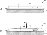
図3は、重量計10が平坦でなく凹凸がある硬い床面Fに設置されている例である。図3Aに示されるように、重量計10は脚部13を備えていることにより、荷重による負荷がない場合には、底面12は床面Fと接触していない。しかし、図3Bに示されるように、重量計10の所定位置に荷重による負荷が加えられると、重量計本体11が撓んで、底面21と床面Fの凸部とが接触してボトミングが発生する場合がある。   FIG. 3 shows an example in which the weighing scale 10 is installed on a hard floor surface F that is not flat and has irregularities. As shown in FIG. 3A, the weight scale 10 includes the leg portion 13, so that the bottom surface 12 is not in contact with the floor surface F when there is no load due to a load. However, as shown in FIG. 3B, when a load due to a load is applied to a predetermined position of the weighing scale 10, the weighing scale main body 11 bends and the bottom surface 21 and the convex portion of the floor surface F come into contact with each other to cause bottoming. There is a case.

重量計10では、平坦で硬い床面Fに重量計10が設置された状態で負荷が加えられて重量計本体11の底面12が撓んでも、その撓みにより、底面12と床面Fとが接触しないように設計されている。しかしながら、床面Fに凹凸がある場合には、床面Fの凸部において、底面12と床面Fとの距離が設計時の想定よりも短くなるため、ボトミングが生じやすくなる。   In the weighing scale 10, even if a load is applied in a state where the weighing scale 10 is installed on a flat and hard floor surface F and the bottom surface 12 of the weighing scale body 11 is bent, the bending causes the bottom surface 12 and the floor surface F to be bent. Designed not to touch. However, if the floor surface F is uneven, the distance between the bottom surface 12 and the floor surface F at the convex portion of the floor surface F is shorter than expected at the time of design, so bottoming is likely to occur.

図4は、重量計10が平坦で硬い床面Fに設置されている例である。図4Aに示されるように、荷重による負荷がない場合には、重量計10の底面12は絨毯Cに接触していない。しかし、図4Bに示されるように、荷重による大きな負荷が重量計10の中央付近に加えられると、重量計本体11が撓んで、底面21と床面Fとが接触してボトミングが発生する場合がある。重量計10は、平坦で硬い床面Fに重量計10を設置して荷重が所定位置に負荷された場合に、重量計本体11の撓み量を勘案して、床面Fに接触しないように設計がなされる。しかし、被測定者が足を中央付近に配置して乗った場合など、所定位置とは異なる位置に荷重が集中した場合にボトミングが生じてしまうことがある。   FIG. 4 shows an example in which the weighing scale 10 is installed on a flat and hard floor surface F. As shown in FIG. 4A, the bottom surface 12 of the weight scale 10 is not in contact with the carpet C when there is no load due to the load. However, as shown in FIG. 4B, when a heavy load due to the load is applied near the center of the weighing scale 10, the weighing scale body 11 bends and the bottom surface 21 and the floor surface F contact to cause bottoming. There is. When the weight scale 10 is installed on a flat and hard floor surface F and a load is applied to a predetermined position, the weight scale 10 is not touched to the floor surface F in consideration of the amount of deflection of the weight scale body 11. Design is made. However, bottoming may occur when the load concentrates at a position different from the predetermined position, such as when the person to be measured rides with his / her foot positioned near the center.

<1.第1の実施の形態>
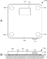
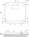
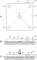
次に、本発明の第1の実施の形態について説明する。図5Aは、本発明の第1の実施の形態に係る重量計100の平面図であり、図5Bは、重量計100の正面図である。図6は、重量計100の機能的構成を示すブロック図である。図7Aは、重量計100の底面図である。図7Bは、重量計100に荷重による負荷がかかっていない状態を示す正面図であり、図7Cは、荷重による負荷により重量計100が撓んでいる状態を示す正面図である。
<1. First Embodiment>
Next, a first embodiment of the present invention will be described. FIG. 5A is a plan view of the weighing scale 100 according to the first embodiment of the present invention, and FIG. 5B is a front view of the weighing scale 100. FIG. 6 is a block diagram showing a functional configuration of the weighing scale 100. FIG. 7A is a bottom view of the weighing scale 100. FIG. 7B is a front view showing a state where a load due to a load is not applied to the weigh scale 100, and FIG. 7C is a front view showing a state where the weight scale 100 is bent due to a load due to the load.

重量計100は、例えば、被測定者が上から乗ることにより体重を測定することが可能な体重計である。なお、下記の第1乃至第3の実施の形態の説明は、重量計が平坦で硬い床面Fの上に載置されており、中央付近に荷重による負荷が加えられた場合を想定して行う。ただし、重量計は絨毯、畳、凹凸がある硬い床面などの面の上でも使用可能であり、それらの上に重量計を設置し、所定位置に荷重による負荷がかかった場合でも同様の効果を奏することができる。   The weight scale 100 is a weight scale that can measure the weight of the person to be measured, for example, by riding from above. In the following description of the first to third embodiments, it is assumed that the weighing scale is placed on a flat and hard floor surface F and a load due to a load is applied near the center. Do. However, weigh scales can also be used on surfaces such as carpets, tatami mats, and hard floors with irregularities, and the same effect can be obtained even if a weight scale is installed on them and a load is applied to a predetermined position. Can be played.

図5Aおよび図5Bに示されるように、重量計100は、上面部102、側面部103および底面部104とから平面視略正方形状に構成された重量計本体101と、四隅において重量計本体101を下から支持する4本の脚部105とを備える。また、重量計100は、底面部104に補正用重量センサ107を備える。なお、重量計本体101の構造についての詳細な説明は省略するが、公知となっている種々の重量計の構造を採用することが可能である。   As shown in FIGS. 5A and 5B, the weighing scale 100 includes a weighing scale body 101 configured in a substantially square shape in plan view from the upper surface portion 102, the side surface portion 103, and the bottom surface portion 104, and the weighing scale body 101 at the four corners. And four leg portions 105 that support from below. The weighing scale 100 includes a correction weight sensor 107 on the bottom surface portion 104. Although a detailed description of the structure of the weighing scale main body 101 is omitted, various known weighing scale structures can be employed.

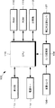
重量計100は、重量センサ106、補正用重量センサ107、A/D(Analog/Digital)変換部108、CPU(Central Processing Unit)109、RAM(Random Access Memory)110、ROM(Read Only Memory)111、記憶部112、表示部113および電源キー114を備える。   The weight scale 100 includes a weight sensor 106, a correction weight sensor 107, an A / D (Analog / Digital) converter 108, a CPU (Central Processing Unit) 109, a RAM (Random Access Memory) 110, and a ROM (Read Only Memory) 111. A storage unit 112, a display unit 113, and a power key 114.

重量センサ106は、上から重量計100にかかる測定対象の重量を測定するものである。重量センサ106は、重量に相当するアナログの電気信号をA/D変換部108に出力する。図5Aにおいて破線で示されるように、重量センサ106は重量計100の内部において、脚部105に対応する位置である重量計100の四隅のそれぞれに設けられている。重量センサ106は、例えば、起歪体と歪ゲージとを有し、荷重による負荷が重量計100にかかったときの荷重に応じて歪む起歪体の歪量を、歪ゲージの抵抗値の変化により測定する。なお、重量センサ106の数はあくまで例示であり、その数は4つに限られるものではない。重量センサ106は、特許請求の範囲における第1重量測定部に相当するものである。   The weight sensor 106 measures the weight of the measuring object applied to the weighing scale 100 from above. The weight sensor 106 outputs an analog electrical signal corresponding to the weight to the A / D converter 108. As indicated by broken lines in FIG. 5A, the weight sensors 106 are provided in each of the four corners of the weighing scale 100, which are positions corresponding to the legs 105, inside the weighing scale 100. The weight sensor 106 includes, for example, a strain-generating body and a strain gauge, and the strain amount of the strain-generating body that is distorted according to the load when the load due to the load is applied to the weight scale 100 is changed by the change in the resistance value of the strain gauge. Measure with The number of weight sensors 106 is merely an example, and the number is not limited to four. The weight sensor 106 corresponds to the first weight measurement unit in the claims.

補正用重量センサ107は、重量計100の底面部104側(脚部を除く)が床面Fに接した際に底面部104側(脚部を除く)にかかる重量を測定するものである。補正用重量センサ107は、重量計100の底面部104において外部に露出するように設けられている。補正用重量センサ107の測定値は、重量センサ106の測定値の補正に用いられる。補正用重量センサ107は、底面部104側(脚部を除く)にかかる重量に相当するアナログの電気信号をA/D変換部108に出力する。補正用重量センサ107は、特許請求の範囲における第2重量測定部に相当するものである。   The correction weight sensor 107 measures the weight applied to the bottom surface portion 104 side (excluding the leg portion) when the bottom surface portion 104 side (excluding the leg portion) of the weighing scale 100 contacts the floor surface F. The correction weight sensor 107 is provided so as to be exposed to the outside at the bottom surface portion 104 of the weighing scale 100. The measurement value of the correction weight sensor 107 is used to correct the measurement value of the weight sensor 106. The correction weight sensor 107 outputs an analog electrical signal corresponding to the weight applied to the bottom surface portion 104 side (excluding the leg portion) to the A / D conversion unit 108. The correction weight sensor 107 corresponds to the second weight measurement unit in the claims.

第1の実施の形態において、補正用重量センサ107は、広範囲において重量を検出/測定することができるシート状の面圧センサを用いて構成されている。第1の実施の形態においては、補正用重量センサ107として面圧センサを用いることにより、図7Aに示されるように、重量計本体101の底面部104の略全面(斜線部分)において重量の測定が可能となっている。重量計本体101の底面部104の略全面において重量の測定が可能なことにより、重量計本体101の底面部104側(脚部を除く)のどの位置が床面Fに接しても底面部104側(脚部を除く)にかかる重量を測定することが可能である。よって、重量計100がどのように撓んでも底面部104側(脚部を除く)にかかる重量を測定することができる。   In the first embodiment, the correction weight sensor 107 is configured using a sheet-like surface pressure sensor capable of detecting / measuring weight over a wide range. In the first embodiment, by using a surface pressure sensor as the correction weight sensor 107, as shown in FIG. 7A, the weight is measured on the substantially entire surface (shaded portion) of the bottom surface portion 104 of the weighing scale body 101. Is possible. Since the weight can be measured on substantially the entire surface of the bottom surface portion 104 of the weighing scale main body 101, the bottom surface portion 104 can be measured regardless of the position on the bottom surface 104 side (excluding the leg portion) of the weighing scale main body 101. It is possible to measure the weight on the side (excluding the legs). Therefore, it is possible to measure the weight applied to the bottom surface portion 104 side (excluding the leg portion) regardless of how the weighing scale 100 is bent.

なお、補正用重量センサ107の測定方式は、重量計本体101の底面で広範囲において測定が可能なものであればどのようなものを採用してもよい。   As the measuring method of the correction weight sensor 107, any method may be adopted as long as the measurement can be performed in a wide range on the bottom surface of the weight main body 101.

A/D変換部108は、重量センサ106および補正用重量センサ107が出力するアナログの信号をデジタルの信号に変換してCPU109に供給するものである。   The A / D converter 108 converts analog signals output from the weight sensor 106 and the correction weight sensor 107 into digital signals and supplies them to the CPU 109.

重量計100は、内部に設けられた制御回路基板(図示せず。)上にCPU109、RAM110、ROM111および記憶部112を備える。CPU109は、RAM110をワークメモリとしてROM111に記憶されたプログラムを実行することにより重量計100の全体および各部の制御、さらに本発明に係る処理を行うものである。ROM111は不揮発性メモリであり、CPU109により読み込まれ動作されるプログラムなどが記憶される。RAM110は、CPU109のワークメモリとして用いられる。記憶部112は、被測定者の体重の測定履歴、被測定者の身長、年齢などの各種データなどを記憶保持する。なお、被測定者は1人に限られず、記憶部112は、複数の被測定者の体重、身長、年齢などをユーザ―データとして記憶保持する事が可能である。   The weigh scale 100 includes a CPU 109, a RAM 110, a ROM 111, and a storage unit 112 on a control circuit board (not shown) provided inside. The CPU 109 executes a program stored in the ROM 111 using the RAM 110 as a work memory, thereby controlling the entire weighing scale 100 and each part, and further performing processing according to the present invention. A ROM 111 is a non-volatile memory, and stores a program read and operated by the CPU 109. The RAM 110 is used as a work memory for the CPU 109. The storage unit 112 stores and holds various data such as the measurement history of the weight of the person to be measured, the height and age of the person to be measured. Note that the measurement subject is not limited to one person, and the storage unit 112 can store and hold the weight, height, age, and the like of a plurality of measurement subjects as user data.

CPU109は、補正用重量センサ107の測定値を用いて重量センサ106の測定値を補正する処理を行う。図7Cに示されるように、重量計100の底面部104側(脚部を除く)が床面Fに接触し、底面部104側(脚部を除く)に重量がかかると、重量センサ106の測定値は実際の測定対象の重量より減少することになる。よって、測定対象の正確な重量を得るために、CPU109は、下記の式(1)を用いて重量センサ106の測定値の補正処理を行う。なお、式(1)において、Wは重量センサ106の測定値の補正後の値であり、w1は重量センサ106の測定値である。また、w2は補正用重量センサ107の測定値であり、aは、補正用重量センサ107の出力感度を重量センサ106の出力感度に整合させるための係数である。   The CPU 109 performs processing for correcting the measurement value of the weight sensor 106 using the measurement value of the correction weight sensor 107. As shown in FIG. 7C, when the bottom surface portion 104 side (excluding the leg portion) of the weighing scale 100 comes into contact with the floor surface F and the bottom surface portion 104 side (excluding the leg portion) is subjected to weight, the weight sensor 106 The measured value will be smaller than the actual weight of the object to be measured. Therefore, in order to obtain an accurate weight of the measurement target, the CPU 109 performs correction processing of the measurement value of the weight sensor 106 using the following formula (1). In Equation (1), W is a value after the measurement value of the weight sensor 106 is corrected, and w1 is a measurement value of the weight sensor 106. Further, w2 is a measurement value of the correction weight sensor 107, and a is a coefficient for matching the output sensitivity of the correction weight sensor 107 with the output sensitivity of the weight sensor 106.

[数1]
W=w1+a・w2・・・・・(1)
[Equation 1]
W = w1 + a · w2 (1)

このように、CPU109は特許請求の範囲における補正処理部に相当するものである。なお、このCPU109により行われる処理は、プログラムによって実現されるのみでなく、同様の処理機能を有するハードウェアによる専用の装置、回路などを組み合わせて実現されてもよい。   Thus, the CPU 109 corresponds to the correction processing unit in the claims. Note that the processing performed by the CPU 109 is not only realized by a program, but may also be realized by combining a dedicated device or circuit using hardware having the same processing function.

表示部113は、例えば、LCD(Liquid Crystal Display)、PDP(Plasma Display Panel)、有機EL(Electro Luminescence)パネルなどにより構成された表示手段である。表示部113は、重量計本体101の上面部102に設けられており、CPU109の制御のもと、測定結果やエラーメッセージなどの各種情報を表示する。   The display unit 113 is a display unit configured by, for example, an LCD (Liquid Crystal Display), a PDP (Plasma Display Panel), an organic EL (Electro Luminescence) panel, or the like. The display unit 113 is provided on the upper surface portion 102 of the weighing scale main body 101 and displays various information such as measurement results and error messages under the control of the CPU 109.

電源キー114は、重量計100の電源をオン/オフを切り替えるための入力手段である。なお、重量計本体101上に荷重による負荷がかかると自動で重量計100の電源がオンとなり、一定期間経過後自動で電源がオフとなるように構成してもよい。   The power key 114 is an input means for switching on / off the power of the weighing scale 100. Note that the weight scale 100 may be automatically turned on when a load due to a load is applied to the weight main body 101 and automatically turned off after a certain period of time.

以上のようにして、第1の実施の形態に係る重量計100が構成されている。   As described above, the weighing scale 100 according to the first embodiment is configured.

次に、図8を参照して、重量計100において行われる重量測定処理について説明する。図8は、重量計100により行われる処理の流れを示すフローチャートである。   Next, the weight measurement process performed in the weighing scale 100 will be described with reference to FIG. FIG. 8 is a flowchart showing a flow of processing performed by the weighing scale 100.

図8に示す動作は、重量計100の電源がオンになることにより開始される。電源がオンになると、重量計100は重量を計測可能な状態になる。まず、表示部113における表示が開始される。このとき、表示部113には、例えば、「0.00kg」と表示される。   The operation shown in FIG. 8 is started when the power of the weighing scale 100 is turned on. When the power is turned on, the weighing scale 100 is ready to measure weight. First, display on the display unit 113 is started. At this time, for example, “0.00 kg” is displayed on the display unit 113.

次に、ステップS11において、重量センサ106により測定対象(例えば、人)の重量が測定される。測定においては、重量センサ106からA/D変換部108を介して供給されたデジタルの信号によって測定結果がCPU109に供給される。次にステップS12で、CPU109により、重量センサ106による測定結果が安定したか否かが判定される。   Next, in step S11, the weight sensor 106 measures the weight of the measurement target (for example, a person). In the measurement, the measurement result is supplied to the CPU 109 by a digital signal supplied from the weight sensor 106 via the A / D conversion unit 108. Next, in step S12, the CPU 109 determines whether or not the measurement result by the weight sensor 106 is stable.

ステップS12で、重量センサ106の測定結果が安定していると判定された場合、処理はステップS13に進む(ステップS12のYes)。次にステップS13で、補正用重量センサ107からA/D変換部108を介して供給されたデジタルの信号で示される補正用重量センサ107の測定値が0であるか否かが判定される。   If it is determined in step S12 that the measurement result of the weight sensor 106 is stable, the process proceeds to step S13 (Yes in step S12). Next, in step S13, it is determined whether or not the measured value of the correction weight sensor 107 indicated by the digital signal supplied from the correction weight sensor 107 via the A / D converter 108 is zero.

補正用重量センサ107による測定値が0である場合、処理はステップS14に進む(ステップS13のYes)。次にステップS14で、CPU109の制御により表示部113に重量センサ106の測定値が測定対象の重量として表示される。そして、重量の測定は終了となる。   If the value measured by the correction weight sensor 107 is 0, the process proceeds to step S14 (Yes in step S13). Next, in step S14, the measurement value of the weight sensor 106 is displayed on the display unit 113 as the weight of the measurement target under the control of the CPU 109. And the measurement of a weight is complete | finished.

補正用重量センサ107の測定値が0であるということは、重量計100の底面部104側(脚部を除く)は床面Fに接触していないということであるため、重量センサ106の測定値に床面Fからの反力による変動はない。よって、重量センサ106の測定結果をそのまま測定対象の重量として表示することができる。   The measurement value of the correction weight sensor 107 being zero means that the bottom surface portion 104 side (excluding the leg portion) of the weighing scale 100 is not in contact with the floor surface F. The value does not vary due to the reaction force from the floor F. Therefore, the measurement result of the weight sensor 106 can be displayed as it is as the weight of the measurement object.

一方、補正用重量センサ107による測定値が0ではない場合、処理はステップS15に進む(ステップS13のNo)。補正用重量センサ107の測定値が0ではないということは、重量計100の底面部104側(脚部を除く)が床面Fに接触していることにより、底面部104側(脚部を除く)に重量がかかっているということである。   On the other hand, when the measured value by the correction weight sensor 107 is not 0, the process proceeds to step S15 (No in step S13). The measurement value of the correction weight sensor 107 is not zero because the bottom surface 104 side (excluding the leg portion) of the weighing scale 100 is in contact with the floor surface F, so (Excluding) is heavy.

次にステップS15で、CPU109により、重量センサ106の測定値の補正処理が行われる。補正処理は、CPU109の説明において上述したものである。重量センサ106の測定値の補正後の値は、RAM110または記憶部112に保存される。   Next, in step S15, the CPU 109 performs correction processing for the measurement value of the weight sensor 106. The correction process has been described above in the description of the CPU 109. The corrected value of the measurement value of the weight sensor 106 is stored in the RAM 110 or the storage unit 112.

次にステップS16で、CPU109の制御によりRAM110または記憶部112に一旦記憶された重量情報が読み出され、重量センサ106の測定値の補正後の値が測定対象の重量として表示部113に表示される。そして、重量の測定は終了となる。   Next, in step S16, the weight information once stored in the RAM 110 or the storage unit 112 is read by the control of the CPU 109, and the corrected value of the measurement value of the weight sensor 106 is displayed on the display unit 113 as the weight of the measurement target. The And the measurement of a weight is complete | finished.

説明はステップS12に戻る。ステップS12で、重量センサ106の測定値が安定していないと判定された場合、処理はステップS17に進む(ステップS12のNo)。重量センサ106の測定値が安定していない場合には、正確な測定値を得ることができないため、ステップS17で、CPU109の制御により、表示部113にエラーを示す旨の表示がなされる。エラー表示としては例えば、「ERROR」という文字列を表示することが考えられる。   The description returns to step S12. If it is determined in step S12 that the measurement value of the weight sensor 106 is not stable, the process proceeds to step S17 (No in step S12). If the measurement value of the weight sensor 106 is not stable, an accurate measurement value cannot be obtained. Therefore, in step S17, the CPU 109 controls the display unit 113 to display an error. As an error display, for example, it is conceivable to display a character string “ERROR”.

なお、重量計100に音声を出力するスピーカーを設けて、表示部113における表示に代えてまたは併せて、「測定エラーです。再測定してください」のような音声ガイダンス、ビーブ音でエラー通知を行ってもよい。また、表示部113にエラーを示す文字列を表示せず、LED(Light Emitting Diode)などの点灯装置(図示略)を設けて、その点灯によりエラーが発生したことを通知するようにしてもよい。   In addition, a speaker for outputting sound is provided in the weigh scale 100, and instead of or in addition to the display on the display unit 113, an error notification is given by a voice guidance such as “Measurement error. You may go. Further, instead of displaying a character string indicating an error on the display unit 113, a lighting device (not shown) such as an LED (Light Emitting Diode) may be provided to notify that an error has occurred due to the lighting. .

以上のようにして、本発明の第1の実施の形態における重量の測定が行われる。第1の実施の形態によれば、重量計100の底面部104側(脚部を除く)にかかる重量を測定する補正用重量センサ107の測定値を用いて重量センサ106の測定値を補正することにより、ボトミングが生じた場合でも正確な重量の測定を行うことができる。   As described above, the weight is measured in the first embodiment of the present invention. According to the first embodiment, the measurement value of the weight sensor 106 is corrected using the measurement value of the correction weight sensor 107 that measures the weight applied to the bottom surface portion 104 side (excluding the leg portion) of the weight scale 100. Thus, even when bottoming occurs, accurate weight measurement can be performed.

また、補正用重量センサ107は、重量計100の底面部104側(脚部を除く)のどの位置が床面Fに接触しても重量計100の底面部104側(脚部を除く)にかかる重量を測定することができるため、重量計100の底面部104側(脚部を除く)のどの位置が床面Fに接しても、正確な重量の測定を行うことができる。   Further, the correction weight sensor 107 is provided on the bottom surface portion 104 side (excluding the leg portion) of the weight scale 100 no matter which position on the bottom surface portion 104 side (excluding the leg portion) of the weight scale 100 contacts the floor surface F. Since such weight can be measured, accurate weight measurement can be performed regardless of the position on the bottom surface 104 side (excluding the leg portion) of the scale 100 in contact with the floor surface F.

<3.第2の実施の形態>
次に、本発明の第2の実施の形態について説明する。なお、第1の実施の形態と同様の構成については同一の符号を援用し、その説明を省略する。
<3. Second Embodiment>
Next, a second embodiment of the present invention will be described. In addition, about the structure similar to 1st Embodiment, the same code | symbol is used and the description is abbreviate | omitted.

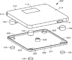
第2の実施の形態における重量計200を構成する重量計本体201は、上側カバー部210と下側カバー部220とを組み合わせることにより構成されている。図9は、上側カバー部210と下側カバー部220の構成を示す分解斜視図である。図10Aは重量計200の平面図であり、図10Bは重量計200の正面図である。   The weight main body 201 constituting the weight scale 200 in the second embodiment is configured by combining the upper cover portion 210 and the lower cover portion 220. FIG. 9 is an exploded perspective view showing configurations of the upper cover part 210 and the lower cover part 220. FIG. 10A is a plan view of the weighing scale 200, and FIG. 10B is a front view of the weighing scale 200.

上側カバー部210は、平面視略長方形状の上面部211と、その上面部211の全周の縁から下方に向かって延出する側面部212とにより、下方が開口した略箱状に構成されている。   The upper cover portion 210 is configured in a substantially box shape having an open bottom by an upper surface portion 211 having a substantially rectangular shape in plan view and a side surface portion 212 extending downward from an edge of the entire periphery of the upper surface portion 211. ing.

下側カバー部220は、平面視略長方形状の底面部221と、その底面部221の全周の縁から上方に向かって延出する側面部222とにより、上方が開口した略箱状に構成されている。下側カバー部220の底面部221は可撓性を有するように構成されている。   The lower cover part 220 is configured in a substantially box-like shape with an open top by a bottom face part 221 having a substantially rectangular shape in plan view and a side face part 222 extending upward from an edge of the entire circumference of the bottom face part 221. Has been. The bottom surface part 221 of the lower cover part 220 is configured to have flexibility.

下側カバー部220の四隅にはそれぞれ、脚部105が挿通するための脚挿通穴223が形成されている。各脚部105は、脚挿通穴223を通り、重量計本体201内部において各重量センサ106のそれぞれに固定されている。なお、下側カバー部220と脚部105とが接触しないように、脚挿通穴223の直径は、脚部105の直径よりもわずかに大きく構成されている。   Leg insertion holes 223 through which the leg portions 105 are inserted are formed at the four corners of the lower cover portion 220, respectively. Each leg 105 passes through the leg insertion hole 223 and is fixed to each weight sensor 106 inside the weighing scale body 201. In addition, the diameter of the leg insertion hole 223 is configured to be slightly larger than the diameter of the leg part 105 so that the lower cover part 220 and the leg part 105 do not contact each other.

上側カバー部210の上面部211は、下側カバー部220の底面部221よりわずかに大きく構成されている。上側カバー部210の内部に下側カバー部220を配置し、上側カバー部210の側面部212と下側カバー部220の側面部222とを固定することにより、重量計本体201が構成されている。上側カバー部210の側面部212と下側カバー部220の側面部222とを固定する方法としては、ねじによる固定、ボルト・ナットによる固定、接着による固定、爪状部材同士の嵌合による固定などがある。ただし、上側カバー部210と下側カバー部220とを固定することができれば固定方法はどのような方法であってもよい。重量センサ106は上側カバー部210と下側カバー部220との間に設けられている。   The upper surface portion 211 of the upper cover portion 210 is configured to be slightly larger than the bottom surface portion 221 of the lower cover portion 220. The weight main body 201 is configured by disposing the lower cover portion 220 inside the upper cover portion 210 and fixing the side surface portion 212 of the upper cover portion 210 and the side surface portion 222 of the lower cover portion 220. . As a method of fixing the side surface portion 212 of the upper cover portion 210 and the side surface portion 222 of the lower cover portion 220, fixing by screws, fixing by bolts and nuts, fixing by adhesion, fixing by fitting between nail-like members, etc. There is. However, any fixing method may be used as long as the upper cover portion 210 and the lower cover portion 220 can be fixed. The weight sensor 106 is provided between the upper cover part 210 and the lower cover part 220.

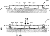
図11Aは、重量計200に荷重による負荷がかかっていない状態を示す、図10AにおけるXI−XI断面図である。図11Bは、荷重による負荷で重量計200が撓んでいる状態を示す、図10AにおけるXI−XI断面図である。   FIG. 11A is a cross-sectional view taken along the line XI-XI in FIG. 10A, showing a state where the weight scale 200 is not loaded with a load. FIG. 11B is a cross-sectional view taken along the line XI-XI in FIG. 10A, showing a state where the weight scale 200 is bent due to a load due to a load.

図11Aに示されるように、重量センサ106は、上端が上側カバー部210に固定され、下端が脚部105に固定されている。さらに、上側カバー部210と下側カバー部220とに挟まれるように補正用重量センサ202が設けられている。本実施の形態においては、補正用重量センサ202は、重量計本体201の略中央に設けられている。   As shown in FIG. 11A, the weight sensor 106 has an upper end fixed to the upper cover portion 210 and a lower end fixed to the leg portion 105. Further, a correction weight sensor 202 is provided so as to be sandwiched between the upper cover part 210 and the lower cover part 220. In the present embodiment, the correction weight sensor 202 is provided substantially at the center of the weight main body 201.

このように重量計200を構成することにより、図11Bに示されるように、ボトミングにより重量計200の底面部221が床面Fと接触すると、床面Fからの反力により、可撓性を有する下側カバー部220の底面部221が上方向に変形して補正用重量センサ202を上方向に押圧することになる。これにより、補正用重量センサ202で底面部221にかかる重量を測定することが可能となる。   By configuring the weighing scale 200 in this way, as shown in FIG. 11B, when the bottom surface portion 221 of the weighing scale 200 comes into contact with the floor surface F by bottoming, the reaction force from the floor surface F causes flexibility. The bottom surface portion 221 of the lower cover portion 220 having the above deforms upward and presses the correction weight sensor 202 upward. As a result, the weight applied to the bottom surface portion 221 can be measured by the correction weight sensor 202.

重量計本体201の底面、すなわち下側カバー部220の底面部221のどの位置が床面Fに接触しても下側カバー部220の底面部221は上方向に変形することになる。よって、ボトミングにより重量計本体201の底面のどの位置が床面Fに接触しても、重量計200の底面部221にかかる重量を測定することが可能である。   Regardless of the position of the bottom surface of the weight main body 201, that is, the bottom surface portion 221 of the lower cover portion 220, the bottom surface portion 221 of the lower cover portion 220 is deformed upward. Therefore, it is possible to measure the weight applied to the bottom surface portion 221 of the weighing scale 200 no matter which position on the bottom surface of the weighing scale body 201 is in contact with the floor surface F by bottoming.

重量計200の機能的構成は図6を参照して説明した第1の実施の形態におけるものと同様である。重量計200により行われる重量測定処理は、図8を参照して説明した第1の実施の形態におけるものと同様である。重量計200の底面部221が床面Fと接触した場合、CPU109は補正用重量センサ202による測定値を用いて重量センサ106による測定値を補正して、補正後の値を正確な重量として表示部113に表示させる。CPU109による重量の補正処理も第1の実施の形態に係るものと同様である。   The functional configuration of the weigh scale 200 is the same as that in the first embodiment described with reference to FIG. The weight measurement process performed by the weigh scale 200 is the same as that in the first embodiment described with reference to FIG. When the bottom surface portion 221 of the weighing scale 200 comes into contact with the floor surface F, the CPU 109 corrects the measurement value by the weight sensor 106 using the measurement value by the correction weight sensor 202 and displays the corrected value as an accurate weight. Displayed on the unit 113. The weight correction process by the CPU 109 is the same as that according to the first embodiment.

本発明の第2の実施の形態によれば、下側カバー部220で補正用重量センサ202が押圧されることにより、重量計200の底面部221のどの場所が床面Fに接しても、重量計200の底面部221にかかる重量を測定することが可能である。これにより、重量計200の底面部221のどの場所が床面Fに接しても、重量センサ106による測定値を補正して、測定対象の正確な重量を得ることができる。   According to the second embodiment of the present invention, the correction weight sensor 202 is pressed by the lower cover portion 220, so that no matter where the bottom surface portion 221 of the weighing scale 200 is in contact with the floor surface F, It is possible to measure the weight applied to the bottom surface part 221 of the weighing scale 200. Thereby, no matter where the bottom surface portion 221 of the weighing scale 200 is in contact with the floor surface F, the measurement value by the weight sensor 106 can be corrected and the accurate weight of the measurement object can be obtained.

<4.第3の実施の形態>
次に、本発明の第3の実施の形態について説明する。なお、第1の実施の形態と同様の構成については同一の符号を援用し、その説明を省略する。
<4. Third Embodiment>
Next, a third embodiment of the present invention will be described. In addition, about the structure similar to 1st Embodiment, the same code | symbol is used and the description is abbreviate | omitted.

図12Aは、第3の実施の形態における重量計300の構成を示す底面図である。図12Bは、荷重による負荷がかかってない状態を示す重量計300の正面図であり、図12Cは、荷重による負荷で重量計300が撓んでいる状態を示す正面図である。なお、重量計300の上面の構成は図5Aに示される第1の実施の形態におけるものと同様である。   FIG. 12A is a bottom view showing the configuration of the weighing scale 300 according to the third embodiment. FIG. 12B is a front view of the weighing scale 300 showing a state where no load is applied due to the load, and FIG. 12C is a front view showing a state where the weighing scale 300 is bent due to the load caused by the load. The configuration of the upper surface of the weighing scale 300 is the same as that in the first embodiment shown in FIG. 5A.

重量計300を構成する重量計本体101は、上面部102、側面部103、底面部104とから箱状に構成されており、第1の実施の形態におけるものと同様のものである。また、重量センサ106は第1の実施の形態と同様に脚部105に対応する位置である重量計300の四隅のそれぞれに設けられている。   A weight main body 101 constituting the weight scale 300 is formed in a box shape from an upper surface portion 102, a side surface portion 103, and a bottom surface portion 104, and is the same as that in the first embodiment. Further, the weight sensors 106 are provided at the four corners of the weighing scale 300, which are positions corresponding to the legs 105, as in the first embodiment.

第3の実施の形態においては、図12Aの破線で示されるように、補正用重量センサ301は、底面部104の4つの脚部105の略中心の位置(各脚部105から等距離の位置)において外部に露出するように設けられている。   In the third embodiment, as indicated by a broken line in FIG. 12A, the correction weight sensor 301 is positioned at substantially the center of the four leg portions 105 of the bottom surface portion 104 (positions equidistant from each leg portion 105. ) To be exposed to the outside.

重量計本体101は、4本の脚部105により支持されている。したがって、重量計本体101は、4つの脚部105の中心位置(各脚部105から等距離の位置)において最も撓みやすいといえる。すなわち、重量計本体101の底面部104側(脚部を除く)は、その中心位置において床面Fと接触する可能性が最も高いといえる。そこで、第3の実施形態では、重量計本体101の底面部104側(脚部を除く)の最も床面Fと接触する可能性が高い位置である、4つの脚部105の中心位置に補正用重量センサ301が設けられている。これにより、底面部104側(脚部を除く)と床面Fとが接触した際に、底面部104側(脚部を除く)にかかる重量を測定することができる。   The weight main body 101 is supported by four leg portions 105. Therefore, it can be said that the weighing scale main body 101 is most easily bent at the center position of the four leg portions 105 (a position equidistant from each leg portion 105). That is, it can be said that the bottom surface portion 104 side (excluding the leg portion) of the weighing scale main body 101 is most likely to come into contact with the floor surface F at the center position. Therefore, in the third embodiment, correction is made to the center position of the four legs 105, which is the position most likely to contact the floor surface F on the bottom face 104 side (excluding the legs) of the scale body 101. A weight sensor 301 is provided. Thereby, when the bottom face part 104 side (except a leg part) and the floor surface F contact, the weight concerning the bottom face part 104 side (except a leg part) can be measured.

なお、重量計300の機能的構成は図6を参照して説明した第1の実施の形態におけるものと同様である。また、重量計300により行われる重量測定処理は、図8を参照して説明した第1の実施の形態におけるものと同様である。重量計300の底面部104側(脚部を除く)が床面Fと接触した場合、CPU109は補正用重量センサ301による測定値を用いて重量センサ106による測定値を補正して、補正後の値を正確な重量として表示部113に表示させる。CPU109による重量の補正処理は、第1の実施の形態におけるものと同様である。   The functional configuration of the weighing scale 300 is the same as that in the first embodiment described with reference to FIG. The weight measurement process performed by the weigh scale 300 is the same as that in the first embodiment described with reference to FIG. When the bottom surface 104 side (excluding the legs) of the weighing scale 300 comes into contact with the floor surface F, the CPU 109 corrects the measurement value obtained by the weight sensor 106 using the measurement value obtained by the correction weight sensor 301, and after the correction. The value is displayed on the display unit 113 as an accurate weight. The weight correction process by the CPU 109 is the same as that in the first embodiment.

第3の実施の形態によれば、重量計100の底面部104側(脚部を除く)の4つの脚部105の中心位置が床面Fと接触して、重量計の底面に重量がかかった場合であっても、重量センサ106の値を補正して測定対象の正確な重量を得ることができる。また、補正用重量センサ301を、重量計本体101を支持する複数の脚部105の中心位置に設けることにより、重量計300の部品点数を少なくし、コスト削減、製造工程の簡略化、さらに重量計300の軽量化などを図ることができる。   According to the third embodiment, the center positions of the four leg portions 105 on the bottom surface portion 104 side (excluding the leg portions) of the weighing scale 100 are in contact with the floor surface F, and the weight is applied to the bottom surface of the weighing scale. Even in this case, the value of the weight sensor 106 can be corrected to obtain an accurate weight of the measurement object. Further, by providing the correction weight sensor 301 at the center position of the plurality of legs 105 that support the weighing scale body 101, the number of parts of the weighing scale 300 can be reduced, the cost can be reduced, the manufacturing process can be simplified, and the weight can be reduced. A total of 300 can be reduced in weight.

本発明の第1乃至第3の実施の形態のいずれにおいても、重量計の底面と床面とが接触しないように脚部を長くするなどして底面と床面との距離を広げる必要がないため、重量計の薄型化を図ることができる。   In any of the first to third embodiments of the present invention, it is not necessary to increase the distance between the bottom surface and the floor surface by elongating the leg portion so that the bottom surface of the weighing scale does not contact the floor surface. For this reason, it is possible to reduce the thickness of the weighing scale.

なお、上述した第1乃至第3の実施の形態における説明は、重量計が平坦で硬い床面Fの上に載置されており、中央付近に荷重による負荷が加わる場合を想定して行った。ただし、重量計が絨毯、畳、凹凸がある硬い床面などの面の上に載置され、中央付近以外の所定位置に荷重を負荷された場合でも実施の形態における説明と同様に測定値の補正を行うことが可能である。   Note that the description in the first to third embodiments described above was made assuming that the weighing scale is placed on a flat and hard floor surface F and a load due to a load is applied near the center. . However, even when the weighing scale is placed on a carpet, tatami mat, or a hard floor with irregularities, and the load is applied to a predetermined position other than the vicinity of the center, the measured value is the same as described in the embodiment. Correction can be performed.

<5.変形例>
以上、本発明の実施の形態について具体的に説明したが、本発明は上述の実施の形態に限定されるものではなく、本発明の技術的思想に基づく各種の変形が可能である。
<5. Modification>
Although the embodiments of the present invention have been specifically described above, the present invention is not limited to the above-described embodiments, and various modifications based on the technical idea of the present invention are possible.

重量計100の形状は、図1などに示される四角形状に限られず、その他の形状、例えば円形状であってもよい。また、上述した実施形態では、脚部105の形状は円柱であるが、脚部105の形状はこれに限られず、例えば、平たい細長の脚部105が2本設けられてもよい。よって、脚部105の本数も4本に限られず、任意の本数でよい。   The shape of the weigh scale 100 is not limited to the quadrangular shape shown in FIG. 1 or the like, but may be other shapes, for example, a circular shape. In the above-described embodiment, the shape of the leg portion 105 is a cylinder, but the shape of the leg portion 105 is not limited to this, and for example, two flat elongated leg portions 105 may be provided. Therefore, the number of leg portions 105 is not limited to four, and may be an arbitrary number.

本発明は、人の体重を計測する体重計の他に、動物用体重計、工業用はかり、料理用はかりなどのはかりや、体重計付の体脂肪計、体重計付の体組織計などのはかりの測定機能を用いた生体測定装置にも適用することが可能である。   The present invention, in addition to a weight scale for measuring a person's weight, such as an animal weight scale, an industrial scale, a cooking scale, a body fat scale with a weight scale, a body tissue scale with a weight scale, etc. The present invention can also be applied to a biometric apparatus that uses a measuring function of a scale.

また、重量に加えて、測定対象である人の体脂肪率、筋肉量などを測定可能な体重計に本発明を適用し、表示部113に、重量以外にも体脂肪率、筋肉量などが表示されるようにすることも可能である。   In addition to the weight, the present invention is applied to a weight scale that can measure the body fat percentage, muscle mass, etc. of the person to be measured, and the display unit 113 displays the body fat percentage, muscle mass, etc. in addition to the weight. It can also be displayed.

上述した重量計により行われる処理はハードウェア、またはソフトウェアにより実行可能である。ソフトウェアによる処理を実行する場合は、処理シーケンスを記録したプログラムを、重量計のROMにインストールして実行させる。プログラムは記憶部としてのハードディスク、メモリまたはROMなどにあらかじめ記録しておくことができる。または、プログラムはCD−ROM(Compact Disc Read Only Memory)、DVD(Digital Versatile Disc)、半導体メモリなどの記録媒体に記録しておくことも可能である。   The processing performed by the above-described weighing scale can be executed by hardware or software. In the case of executing processing by software, a program in which a processing sequence is recorded is installed in the ROM of the weigh scale and executed. The program can be recorded in advance in a hard disk, memory, or ROM as a storage unit. Alternatively, the program can be recorded on a recording medium such as a CD-ROM (Compact Disc Read Only Memory), a DVD (Digital Versatile Disc), or a semiconductor memory.

また、本発明の係る処理を行うプログラムを格納した記録媒体は、パッケージソフトウェアとして提供することができる。使用者はそのパッケージソフトウェアを撮像装置にインストールする。さらに、プログラムは記録媒体からにインストールするほかに、重量計100をインターネットに接続し、インターネットにおいてアプリケーションとして提供されるものをインストールすることも可能である。   A recording medium storing a program for performing the processing according to the present invention can be provided as package software. The user installs the package software on the imaging apparatus. Further, in addition to installing the program from the recording medium, it is also possible to connect the weigh scale 100 to the Internet and install what is provided as an application on the Internet.

100、200、300・・・重量計
101、201・・・・・・・重量計本体
105・・・・・・・・・・・脚部
106・・・・・・・・・・・重量センサ
107、202、301・・・補正用重量センサ
109・・・・・・・・・・・CPU
210・・・・・・・・・・・上側カバー部
220・・・・・・・・・・・下側カバー部
100, 200, 300 ... Weigh scales 101, 201 ················································· Weight Sensors 107, 202, 301 ... Weight sensor 109 for correction ... CPU
210 ... upper cover part 220 ... lower cover part

Claims (6)

本体と、
荷重に応じた重量を測定する第1重量測定部と、
前記本体の底面にかかる重量を測定する第2重量測定部と、
前記第2重量測定部による測定結果を用いて、前記第1重量測定部による測定結果を補正する補正処理部と
を備える重量計。
The body,
A first weight measuring unit for measuring a weight according to a load;
A second weight measuring unit for measuring the weight applied to the bottom surface of the main body;
A weighing scale comprising: a correction processing unit that corrects a measurement result obtained by the first weight measurement unit using a measurement result obtained by the second weight measurement unit.
床面上に起立し、前記本体を前記床面から離間した状態で支持する複数の脚部を備え、
前記第2重量測定部は、前記本体にかかる荷重によって前記本体と前記床面とが接触することにより前記本体の底面にかかる重量を測定する
請求項1に記載の重量計。
A plurality of legs that stand on the floor and support the body in a state of being separated from the floor;
The weighing machine according to claim 1, wherein the second weight measuring unit measures a weight applied to a bottom surface of the main body when the main body and the floor surface come into contact with each other by a load applied to the main body.
前記第2重量測定部は、前記本体の底面の全面に設けられている
請求項1または2に記載の重量計。
The weight scale according to claim 1, wherein the second weight measuring unit is provided on the entire bottom surface of the main body.
前記本体の上側を構成する上側カバー部と、
前記本体の下側を構成し、前記本体の底面にかかる重量により上方向に変形可能な下側カバー部と
を備え、
前記第2重量測定部は、前記上側カバー部と前記下側カバー部との間に設けられており、前記下側カバー部が上方向に変形することにより前記第2重量測定部にかかる重量を測定する
請求項1または2に記載の重量計。
An upper cover part constituting the upper side of the main body;
Comprising the lower side of the main body, and a lower cover part that can be deformed upward by the weight applied to the bottom surface of the main body,
The second weight measuring part is provided between the upper cover part and the lower cover part, and the weight applied to the second weight measuring part when the lower cover part is deformed upward. The weighing scale according to claim 1 or 2, which is measured.
前記第2重量測定部は、前記本体の底面における前記複数の脚部から等距離の位置に設けられている
請求項2に記載の重量計。
The weight scale according to claim 2, wherein the second weight measuring unit is provided at a position equidistant from the plurality of legs on the bottom surface of the main body.
荷重に応じた重量を測定し、
本体の底面にかかる重量を測定し、
前記本体の底面にかかる重量の測定結果を用いて、前記荷重に応じた重量の測定結果を補正する
重量測定方法。
Measure the weight according to the load,
Measure the weight on the bottom of the body,
A weight measurement method for correcting a weight measurement result according to the load using a weight measurement result applied to a bottom surface of the main body.
JP2013254028A 2013-12-09 2013-12-09 Weigh scale and weight measuring method Pending JP2015114115A (en)

Priority Applications (1)

Application Number Priority Date Filing Date Title
JP2013254028A JP2015114115A (en) 2013-12-09 2013-12-09 Weigh scale and weight measuring method

Applications Claiming Priority (1)

Application Number Priority Date Filing Date Title
JP2013254028A JP2015114115A (en) 2013-12-09 2013-12-09 Weigh scale and weight measuring method

Publications (1)

Publication Number Publication Date
JP2015114115A true JP2015114115A (en) 2015-06-22

Family

ID=53528061

Family Applications (1)

Application Number Title Priority Date Filing Date
JP2013254028A Pending JP2015114115A (en) 2013-12-09 2013-12-09 Weigh scale and weight measuring method

Country Status (1)

Country Link
JP (1) JP2015114115A (en)

Cited By (3)

* Cited by examiner, † Cited by third party
Publication number Priority date Publication date Assignee Title
JP2022112809A (en) * 2021-01-22 2022-08-03 パナソニックIpマネジメント株式会社 Weight sensor unit
JP2022112810A (en) * 2021-01-22 2022-08-03 パナソニックIpマネジメント株式会社 Weight sensor unit
CN116124267A (en) * 2022-12-28 2023-05-16 深圳市晨北科技有限公司 Method, device, equipment and storage medium for determining weighing result

Cited By (5)

* Cited by examiner, † Cited by third party
Publication number Priority date Publication date Assignee Title
JP2022112809A (en) * 2021-01-22 2022-08-03 パナソニックIpマネジメント株式会社 Weight sensor unit
JP2022112810A (en) * 2021-01-22 2022-08-03 パナソニックIpマネジメント株式会社 Weight sensor unit
JP7437770B2 (en) 2021-01-22 2024-02-26 パナソニックIpマネジメント株式会社 weight sensor unit
JP7437769B2 (en) 2021-01-22 2024-02-26 パナソニックIpマネジメント株式会社 weight sensor unit
CN116124267A (en) * 2022-12-28 2023-05-16 深圳市晨北科技有限公司 Method, device, equipment and storage medium for determining weighing result

Similar Documents

Publication Publication Date Title
CN101629844B (en) Weighing scale and method of controlling weighing scale
JP5097562B2 (en) Electronic weighing scale
US9366588B2 (en) Devices, systems and methods to determine area sensor
EP2327968B1 (en) Weight measuring apparatus for use as an input device of a game apparatus
US10088937B2 (en) Touch input device including a moment compensated bending sensor for load measurement on platform supported by bending beams
US9759599B2 (en) Weighing device having inductive sensing elements
US20150177899A1 (en) Elastomeric shear Material Providing Haptic Response Control
JP5107388B2 (en) Mobile communication terminal
JP2010078439A (en) Electronic weight meter and method for detecting inclination
US9395234B2 (en) Stabilizing base for scale
CN103354921B (en) touch sensitive display
JP5898779B2 (en) INPUT DEVICE AND METHOD FOR DETECTING MULTI-POINT LOAD USING THE INPUT DEVICE
JP2015114115A (en) Weigh scale and weight measuring method
WO2017143358A9 (en) Height measuring device
US20170030765A1 (en) Self-leveling scale
JP6170774B2 (en) MEASUREMENT SYSTEM, MEASUREMENT DEVICE MEASUREMENT METHOD, MEASUREMENT DEVICE, AND MEASUREMENT DEVICE CONTROL PROGRAM
JP5992698B2 (en) Load measuring system and information processing apparatus
CN106456027A (en) Measuring device and measuring method
JP4982462B2 (en) Weight scale
JP5893966B2 (en) Load measuring system and information processing apparatus
KR20160141922A (en) Apparatus for testing skin friction
KR20140050233A (en) Load measurement apparatus and capacitive-type load sensing unit therefor
JP2012200262A (en) Biological information measuring apparatus
HK1128520A (en) Weighing scale