JP2015114107A - Radiation shielding wall construction form and radiation shielding wall construction method using the same - Google Patents
Radiation shielding wall construction form and radiation shielding wall construction method using the same Download PDFInfo
- Publication number
- JP2015114107A JP2015114107A JP2013253833A JP2013253833A JP2015114107A JP 2015114107 A JP2015114107 A JP 2015114107A JP 2013253833 A JP2013253833 A JP 2013253833A JP 2013253833 A JP2013253833 A JP 2013253833A JP 2015114107 A JP2015114107 A JP 2015114107A
- Authority
- JP
- Japan
- Prior art keywords
- radiation shielding
- shielding wall
- wall construction
- vertical
- reinforcing bar
- Prior art date
- Legal status (The legal status is an assumption and is not a legal conclusion. Google has not performed a legal analysis and makes no representation as to the accuracy of the status listed.)
- Granted
Links
Images


Landscapes
- Building Environments (AREA)
Abstract
Description
本発明は、病院のレントゲン室や低濃度放射物汚染物質を保管する保管室の放射線遮蔽壁等の構築に用いる放射線遮蔽壁構築用型枠およびそれを用いた放射線遮蔽壁構築工法に関する。 The present invention relates to a radiation shielding wall construction form used for construction of a radiation shielding wall or the like of a storage room for storing a radiological room or a low-concentration radioactive contaminant, and a radiation shielding wall construction method using the same.
従来、放射線遮蔽壁を構築するため、開口部に型枠を設置し、放射線遮蔽材を混入したコンクリートを打設して固化させた後、型枠を除去する工法や、鋼板で補強された放射線遮蔽ボードを鋼板で補強したものを積層し、これらを組み立てて構築する工法等が提案されている。 Conventionally, in order to build a radiation shielding wall, a formwork is installed in the opening, and after placing concrete with radiation shielding material and solidifying it, a method of removing the formwork or radiation reinforced with steel plates A construction method has been proposed in which shielding boards reinforced with steel plates are laminated and assembled.
しかしながら、従来の放射線遮蔽壁構築は、型枠組立て作業に時間を要し、壁厚を厚くしない十分な放射線遮蔽ができないという問題と、耐震性能が十分でないという問題を有していた。 However, the conventional radiation shielding wall construction has a problem that it takes time to assemble the formwork, the radiation cannot be sufficiently shielded without increasing the wall thickness, and the seismic performance is not sufficient.
本発明は、従来技術のもつ課題を解決する、構造が簡単で組み立て作業が容易で、耐震性能が高く、確実に放射線遮蔽が可能な放射線遮蔽壁を構築することが可能なコンクリートと一体化する放射線遮蔽壁構築用型枠とそれを用いた放射線遮蔽壁構築工法を提供することを目的とする。 The present invention solves the problems of the prior art and is integrated with concrete capable of constructing a radiation shielding wall that is simple in structure, easy to assemble, has high earthquake resistance, and can reliably shield radiation. An object of the present invention is to provide a radiation shielding wall construction form and a radiation shielding wall construction method using the same.
本発明の放射線遮蔽壁構築用型枠は、前記課題を解決するために、縦方向及び横方向に複数連設し、一定間隔をおいて向かい合うように縦方向及び横方向に複数連設して放射線遮蔽壁を構築する空間を形成する放射線遮蔽壁構築用型枠において、平板部の両端部に前記平板部に対して直角に伸びる側壁部を形成した水平切断面がコ字形の型枠本体と、前記型枠本体の上下に内側に水平に伸びるように形成される上下フランジ部と、前記上下フランジ部間に形成される垂直部と、前記上下フランジ部の前端から垂直に上下又はいずれか一方に伸びる複数の上下位置決め用爪部材と、前記垂直部の側端から水平に左右またはいずれか一方に伸びる複数の左右位置決め用爪部材と、前記平板部の内側面に配置される放射線遮蔽材と、を備えることを特徴とする。 In order to solve the above-described problem, the form for constructing a radiation shielding wall according to the present invention includes a plurality of columns in the vertical direction and the horizontal direction, and a plurality of columns in the vertical direction and the horizontal direction so as to face each other at a predetermined interval. In a radiation shielding wall construction mold for forming a space for constructing a radiation shielding wall, a horizontal cutting plane in which a side wall portion extending at right angles to the flat plate portion is formed at both ends of the flat plate portion is a U-shaped mold body. An upper and lower flange portion formed so as to extend horizontally inwardly on the upper and lower sides of the mold body, a vertical portion formed between the upper and lower flange portions, and vertically up or down from the front end of the upper and lower flange portion A plurality of vertical positioning claw members extending horizontally, a plurality of left and right positioning claw members extending horizontally from the side end of the vertical portion to either the left or right, and a radiation shielding material disposed on the inner surface of the flat plate portion, To provide And butterflies.
また、本発明の放射線遮蔽壁構築用型枠は、前記放射線遮蔽材の上に断熱材を配置することを特徴とする。 The radiation shielding wall construction mold according to the present invention is characterized in that a heat insulating material is disposed on the radiation shielding material.
また、本発明の放射線遮蔽壁構築用型枠は、前記上下フランジ部に縦鉄筋を挿通する縦鉄筋用孔を複数形成し、前記側壁部に横鉄筋を挿通する横鉄筋用孔を複数形成し、前記垂直部に幅方向の鉄筋を挿通する幅鉄筋用孔を複数形成することを特徴とする。 The radiation shielding wall construction mold according to the present invention has a plurality of vertical reinforcing bar holes through which the vertical reinforcing bars are inserted in the upper and lower flange parts, and a plurality of horizontal reinforcing bar holes through which the horizontal reinforcing bars are inserted. A plurality of width reinforcing bar holes through which the reinforcing bars in the width direction are inserted are formed in the vertical portion.
また、本発明の放射線遮蔽壁構築用型枠は、縦鉄筋、横鉄筋及び幅鉄筋を螺旋鉄筋とし、縦方向に連設される複数の放射線遮蔽壁構築用型枠の一番下と一番上に位置する縦鉄筋用孔の周囲及び横方向に連設される複数の放射線遮蔽壁構築用型枠の右端と左端に位置する横鉄筋用孔の周囲に螺旋鉄筋と螺着するナットを収容する凹部を形成することを特徴とする。 The radiation shielding wall construction form of the present invention includes a vertical reinforcing bar, a horizontal reinforcing bar, and a width reinforcing bar that are helical reinforcing bars, and the lowest and first of the plurality of radiation shielding wall construction forms that are arranged in the vertical direction. Accommodates nuts to be screwed to the spiral reinforcing bars around the vertical reinforcing bar holes located above and around the horizontal reinforcing bar holes located at the right and left ends of a plurality of radiation shielding wall construction molds arranged in the horizontal direction. A concave portion to be formed is formed.
また、本発明の放射線遮蔽壁構築工法は、一方の側に請求項1ないし請求項4のいずれかの放射線遮蔽壁構築用型枠を縦方向及び横方向に複数連設し、一定間隔をおいてする他方の側に向かい合わせて放射線遮蔽壁構築用型枠を縦方向及び横方向に複数連設して放射線遮蔽壁構築用空間を形成し、幅鉄筋用孔、縦鉄筋用孔および横鉄筋用孔に幅鉄筋、縦鉄筋および幅鉄筋を挿通し、各鉄筋の両端にナットを螺着して連設した複数の放射線遮蔽壁構築用型枠を固定し、放射線遮蔽壁構築用空間にコンクリートを打設して固化させて、連設した複数の放射線遮蔽壁構築用型枠とコンクリートを一体化することを特徴とする。
In the radiation shielding wall construction method of the present invention, a plurality of radiation shielding wall construction molds according to any one of
また、本発明の放射線遮蔽壁構築工法は、連設した放射線遮蔽壁構築用型枠の平板部の外側表面に繊維シートを張り付けることを特徴とする。 Further, the radiation shielding wall construction method of the present invention is characterized in that a fiber sheet is attached to the outer surface of the flat plate portion of the continuous radiation shielding wall construction form.
縦方向及び横方向に複数連設し、一定間隔をおいて向かい合うように縦方向及び横方向に複数連設して放射線遮蔽壁を構築する空間を形成する放射線遮蔽壁構築用型枠において、平板部の両端部に前記平板部に対して直角に伸びる側壁部を形成した水平切断面がコ字形の型枠本体と、前記型枠本体の上下に内側に水平に伸びるように形成される上下フランジ部と、前記上下フランジ部間に形成される垂直部と、前記上下フランジ部の前端から垂直に上下又はいずれか一方に伸びる複数の上下位置決め用爪部材と、前記垂直部の側端から水平に左右またはいずれか一方に伸びる複数の左右位置決め用爪部材と、前記平板部の内側面に配置される放射線遮蔽材と、を備えることで、組立て作業が容易で、コンクリートと一体化して放射線遮蔽性能の高い放射線遮蔽壁を構築することが可能となる。
放射線遮蔽材の上に断熱材を配置することで、型枠内にコンクリートを打設する際、放射線遮蔽材の破損を防止し、構築された放射線遮蔽壁表面の温度差による結露を防止することが可能となる。
上下フランジ部に縦鉄筋を挿通する縦鉄筋用孔を複数形成し、前記側壁部に横鉄筋を挿通する横鉄筋用孔を複数形成し、前記垂直部に幅方向の鉄筋を挿通する幅鉄筋用孔を複数形成することで、連設された複数の放射線型枠を固定することができ、コンクリート一体化して耐震性能の高い放射線遮蔽壁を構築することが可能となる。
縦鉄筋、横鉄筋及び幅鉄筋を螺旋鉄筋とし、縦方向に連設される複数の放射線遮蔽壁構築用型枠の一番下と一番上に位置する縦鉄筋用孔の周囲及び横方向に連設される複数の放射線遮蔽壁構築用型枠の右端と左端に位置する横鉄筋用孔の周囲に螺旋鉄筋と螺着するナットを収容する凹部を形成することで、連設した放射線遮蔽壁構築用型枠の上下、左右の表面に突出物が存在しないようにすることが可能となる。
一方の側に請求項1ないし請求項4のいずれかの放射線遮蔽壁構築用型枠を縦方向及び横方向に複数連設し、一定間隔をおいてする他方の側に向かい合わせて放射線遮蔽壁構築用型枠を縦方向及び横方向に複数連設して放射線遮蔽壁構築用空間を形成し、幅鉄筋用孔、縦鉄筋用孔および横鉄筋用孔に幅鉄筋、縦鉄筋および幅鉄筋を挿通し、各鉄筋の両端にナットを螺着して連設した複数の放射線遮蔽壁構築用型枠を固定し、放射線遮蔽壁構築用空間にコンクリートを打設して固化させて、連設した複数の放射線遮蔽壁構築用型枠とコンクリートを一体化することで、連設した複数の放射線遮蔽壁構築用型枠を固定し、打設したコンクリートと一体化し、放射線遮蔽性能及び耐震性能の高い放射線遮蔽壁を短い作業時間で構築することが可能となる。
連設した放射線遮蔽壁構築用型枠の平板部の外側表面に繊維シートを張り付けることで、放射線遮蔽壁表面の美観を向上させると共に放射線遮蔽壁の強度を向上させることが可能となる。
In a radiation shielding wall construction form that forms a space for constructing a radiation shielding wall by continuously arranging a plurality of longitudinal and lateral directions and facing each other at a predetermined interval in the longitudinal direction and the lateral direction. A horizontal cut surface in which side wall portions extending at right angles to the flat plate portion are formed at both ends of the flat portion, and a vertical flange formed so as to extend horizontally inwardly above and below the mold body A vertical portion formed between the upper and lower flange portions, a plurality of vertical positioning pawl members extending vertically up or down from the front end of the upper and lower flange portions, and horizontally from the side end of the vertical portion Equipped with a plurality of left and right positioning claw members that extend to the left and right or either side, and a radiation shielding material disposed on the inner surface of the flat plate portion, making it easy to assemble and radiation shielding performance integrated with concrete It is possible to construct a high radiation shielding wall.
By placing a heat insulating material on the radiation shielding material, when concrete is placed in the formwork, the radiation shielding material is prevented from being damaged and dew condensation due to the temperature difference of the constructed radiation shielding wall surface is prevented. Is possible.
For vertical reinforcing bars, multiple vertical reinforcing bar holes for inserting vertical reinforcing bars are formed in the upper and lower flange parts, multiple horizontal reinforcing bar holes for inserting horizontal reinforcing bars are formed in the side wall parts, and reinforcing bars in the width direction are inserted in the vertical part. By forming a plurality of holes, it is possible to fix a plurality of continuous radiation molds, and it is possible to construct a radiation shielding wall having high earthquake resistance by integrating concrete.
Vertical reinforcing bars, horizontal reinforcing bars and width reinforcing bars are spiral reinforcing bars, and around the vertical reinforcing bar holes located at the bottom and top of a plurality of radiation shielding wall construction forms arranged in the vertical direction. A radiation shielding wall provided continuously by forming a recess that accommodates a nut that is screwed to the spiral reinforcing bar around the holes for the horizontal reinforcing bars located at the right end and the left end of the plurality of radiation shielding wall construction molds that are provided continuously. It is possible to prevent protrusions on the upper and lower surfaces and the left and right surfaces of the building form.
A plurality of the radiation shielding wall construction molds according to any one of
By sticking the fiber sheet on the outer surface of the flat plate portion of the radiation shielding wall construction form that is continuously provided, the appearance of the radiation shielding wall surface can be improved and the strength of the radiation shielding wall can be improved.
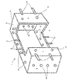
本発明の実施形態を図により説明する。図1は、本発明の放射線遮蔽壁構築用型枠1の斜視図、図2は、上面図、図3は正面図、図4は、図3の切断面図である。
An embodiment of the present invention will be described with reference to the drawings. 1 is a perspective view of a radiation shielding
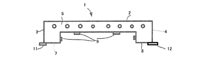
放射線遮蔽壁構築用型枠1は、矩形の平板部2の両側端から直角に伸びる左側壁部3と右側壁部4を有する水平切断面がコ字形の型枠本体を有する。型枠本体の上下に内側に水平に伸びる上フランジ部5と下フランジ部6が形成される。左側壁部3の先端部と上下フランジ部5、6とが接する部分に左垂直部7が形成され、右側壁部4と上下フランジ部5,6とが接する部分に右垂直部8が形成される。
The radiation shielding
上フランジ部5の先端に垂直に上方に伸びる上位置決め用爪部材9が複数固定される。下フランジ部6の先端に垂直に下方に伸びる下位置決め用爪部材10が複数固定される。上位置決め爪部材9と下位置決め用爪部材10は縦方向に連設する際互いが干渉しない位置に固定される。また、複数の放射線遮蔽壁構築用型枠1を縦方向に連設する場合、一番下に位置する放射線遮蔽壁構築用型枠1の下フランジ部6には下位置決め用爪部材10を配置せず、一番上に位置する放射線遮蔽壁構築用型枠1の上フランジ部5には上位置決め用爪部材9を配置しない。
A plurality of upper
左垂直部7の側端に水平に横方向に伸びる左位置決め爪部材11が複数固定される。右垂直部8の側端に水平に横方向に伸びる右位置決め爪部材12が固定される。左位置決め爪部材11と右位置決め爪部材12は横方向に連設する際互いが干渉しない位置に固定される。また、放射線遮蔽壁構築用型枠1を横方向い連設する場合、左端に位置する放射線遮蔽壁型枠構築用型枠1の左垂直部7には左位置決め爪部材11を配置せず、右端に位置する放射線遮蔽壁型枠構築用型枠1の右垂直部8には右位置決め爪部材12を配置しない。
A plurality of left
上下フランジ部5、6には、平板部2に平行に縦鉄筋用孔13が複数形成される。左右側壁部3、4には、横鉄筋用孔14が縦方向に複数形成される。縦鉄筋用孔13と横鉄筋用孔14は、縦鉄筋と横鉄筋が互いに干渉しない位置に形成される。左垂直部7と右垂直部8に幅鉄筋用孔15が縦方向に複数形成される。
A plurality of vertical
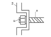
図4に示されるように、型枠本体の平板部2の内側に放射線遮蔽材16を配置する。放射線遮蔽材16としては、鉛板や無鉛ボード等である。無鉛ボードは、硫酸バリウムを石膏と混合し、ガラス繊維で補強した硫酸バリウム混合石膏ボードを素材として形成されており、放射線遮蔽の効果が高く軽量であるのが特徴である。
As shown in FIG. 4, the
放射線遮蔽材16の上には断熱材17を配置する。断熱材17としては発泡スチロール等である。断熱材17は、型枠内にコンクリート打設の際、放射線遮蔽材16がコンクリート打設により破損するのを防止すると共に、構築された放射線遮蔽壁表面の温度の変化による結露を防止する機能を有する。
A
放射線遮蔽壁構築用型枠1を用いた放射線遮蔽壁構築工法について図5、図6、図7、図8により説明する。
A radiation shielding wall construction method using the radiation shielding
先ず、一方の側の放射線遮蔽型枠1と他方側に向き合うように配置した放射線遮蔽型枠1との左垂直部7、右垂直部8に形成した複数の幅鉄筋用孔15に螺旋鉄筋からなる幅鉄筋18を挿入し、左垂直部7、右垂直部8の表裏にナット21、21を螺着し、放射線遮蔽壁構築用型枠1,1間の間隔を設計された放射線遮蔽壁の厚みになるように保持する。
First, a spiral reinforcing bar is used to form a plurality of width reinforcing bar holes 15 formed in the left
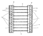
図5に示す実施形態では、幅鉄筋18により間隔が保持された1対の放射線遮蔽壁構築用型枠1を、横方向に3個、縦方向に3個連設する。複数の放射線遮蔽壁構築用型枠1を縦方向と横方向に連設する際、上下位置決め用爪部材9、10と左右位置決め用爪部材11、12が正確に位置決めする。連設する放射線遮蔽壁構築用型枠1の内、一番上に位置するものには上位置決め用爪部材9を配置せず、一番下に位置するものには下位置決め用爪部材10を配置しない。また、左端に位置するものには左位置決め爪部材11を配置せず、右端に位置するものには右位置決め爪部材12を配置しない。このようにすることにより連設した複数の放射線遮蔽壁構築用型枠1の上下、左右に位置決め爪部材を突出させない。
In the embodiment shown in FIG. 5, three pairs of radiation shielding
放射線遮蔽壁構築用型枠1の連設個数は構築される放射線遮蔽壁の大きさにより変化する。縦方向、横方向に連設した放射線遮蔽壁構築用型枠1の上下フランジ部5、6に形成した縦鉄筋用孔13に螺旋鉄筋からなる縦鉄筋13を挿入し、縦鉄筋13の両端部をナット21で螺着し固定する。
The number of the radiation shielding
図7に示すように、連設する放射線遮蔽壁構築用型枠1の内、一番上に位置する上フランジ部5に形成した縦鉄筋用孔13の周囲と、一番下には位置する下フランジ部6に形成した縦鉄筋用孔13の周囲にナット21を収容し、縦鉄筋13の上端部及び下端部が上フランジ部5及び下フランジ部6の表面から突出しないようにする凹部を形成する。
As shown in FIG. 7, it is located in the periphery of the
図6に示すよう、連設する放射線遮蔽壁構築用型枠1の内、左端に位置する左側壁部35に形成した横鉄筋用孔14の周囲と、右端には位置する右側壁部4に形成した横鉄筋用孔14の周囲にナット21を収容し、横鉄筋14の端部が左側壁部3及び右側壁部4の表面から突出しないようにする凹部を形成する。このようにすることにより連設した複数の放射線遮蔽壁構築用型枠1の上下、左右表面から突出する部材を無くすことが可能となる。
As shown in FIG. 6, in the radiation shielding
図8は、連設した複数の放射線遮蔽壁構築用型枠1に幅鉄筋18、縦鉄筋19及び横鉄筋20は配置しナット21で固定した状態を示す水平切断面を示す図である。この状態では、連設された複数の放射線遮蔽壁構築用型枠1は固定されているので、大きさ、重量等から運搬可能ならば、図8に示す状態まで工場で組み立て、放射線遮蔽壁構築現場まで搬送し、構築位置に嵌め込むことで作業効率を上げることができる。コンクリートを打設し、コンクリートと幅鉄筋18、縦鉄筋19及び横鉄筋20は配置した複数の放射線遮蔽壁構築用型枠1とを一体化した後、壁面となる連設された放射線遮蔽壁構築用型枠1の平板部2上に繊維シートを張り付ける。繊維シートを張り付けることで放射線遮蔽壁の美観を向上させ、強度も向上させることが可能となる。
FIG. 8 is a view showing a horizontal cut surface showing a state in which the
以上のように、本発明の放射線遮蔽壁構築用型枠とそれを用いた放射線遮蔽壁構築方法によれば、構造が簡単で組み立て作業が容易で、耐震性能が高く、確実に放射線遮蔽が可能な放射線遮蔽壁を構築することが可能となる。 As described above, according to the radiation shielding wall construction form of the present invention and the radiation shielding wall construction method using the same, the structure is simple, the assembling work is easy, the seismic performance is high, and the radiation shielding can be surely performed. It becomes possible to construct a simple radiation shielding wall.
1:放射線遮蔽壁構築用型枠、2:平板部、3:左側壁部、4:右側壁部、5:上フランジ部、6:下フランジ部、7:左垂直部、8:右垂直部、9:上位置決め用爪部材、10:下位置決め用爪部材、11:左位置決め爪部材、12:右位置決め爪部材、13:縦鉄筋用孔、14:横鉄筋用孔、15:幅鉄筋用孔、16:放射線遮蔽材、17:断熱材、18:幅鉄筋、19:縦鉄筋、20:横鉄筋、21:ナット、 1: Radiation shielding wall construction form, 2: Flat plate part, 3: Left side wall part, 4: Right side wall part, 5: Upper flange part, 6: Lower flange part, 7: Left vertical part, 8: Right vertical part 9: Upper positioning claw member, 10: Lower positioning claw member, 11: Left positioning claw member, 12: Right positioning claw member, 13: Vertical reinforcing bar hole, 14: Horizontal reinforcing bar hole, 15: For wide reinforcing bar Hole, 16: radiation shielding material, 17: heat insulating material, 18: width reinforcing bar, 19: vertical reinforcing bar, 20: horizontal reinforcing bar, 21: nut,
本発明の放射線遮蔽壁構築用型枠は、前記課題を解決するために、縦方向及び横方向に複数連設し、一定間隔をおいて向い合せに縦方向及び横方向に複数連設して放射線遮蔽壁を構築する空間を形成する放射線遮蔽壁構築用型枠において、矩形の平板部の両側端に前記平板部に対して直角に伸びる側壁部を形成した水平切断面がコ字形の型枠本体と、前記型枠本体の上下に内側に水平に伸びるように形成される上下フランジ部と、前記上下フランジ部間に形成される垂直部と、前記上下フランジ部の前端から垂直に上下又はいずれか一方に伸びる複数の上下位置決め用爪部材と、前記垂直部の側端から水平に左右またはいずれか一方に伸びる複数の左右位置決め用爪部材と、前記平板部の内側面に配置される放射線遮蔽材と、前記放射線遮蔽材の上に配置される断熱材と、を備え、前記上下フランジ部に縦鉄筋を挿通する縦鉄筋用孔を複数形成し、前記側壁部に横鉄筋を挿通する横鉄筋用孔を複数形成し、前記垂直部に幅方向の鉄筋を挿通する幅鉄筋用孔を複数形成することを特徴とする。 In order to solve the above-described problem, the form for building a radiation shielding wall according to the present invention includes a plurality of continuous lines in the vertical direction and the horizontal direction, and a plurality of lines in the vertical direction and the horizontal direction facing each other at regular intervals. In a radiation shielding wall construction form for forming a space for constructing a radiation shielding wall, a horizontal cut surface in which a side wall portion extending at right angles to the flat plate portion is formed on both side ends of a rectangular flat plate portion is a U-shaped form A main body, an upper and lower flange portion formed so as to extend horizontally in the upper and lower sides of the mold main body, a vertical portion formed between the upper and lower flange portions, and vertically up or down from the front end of the upper and lower flange portion A plurality of vertical positioning claw members extending to one side, a plurality of left and right positioning claw members extending horizontally from the side end of the vertical portion to the left or right, and a radiation shield disposed on the inner surface of the flat plate portion and wood, the radiation shielding And a heat insulating material disposed on the, the vertical rebar hole for inserting the longitudinal reinforcing bars to said upper and lower flanges to form a plurality, a horizontal reinforcing bar holes for inserting the transverse reinforcing bars plurality formed in the side wall portion, A plurality of width reinforcing bar holes through which the reinforcing bars in the width direction are inserted are formed in the vertical portion .
また、本発明の放射線遮蔽壁構築用型枠は、縦方向に連設される複数の放射線遮蔽壁構築用型枠の一番下と一番上に位置する縦鉄筋用孔の周囲及び横方向に連設される複数の放射線遮蔽壁構築用型枠の右端と左端に位置する横鉄筋用孔の周囲にナットを収容する凹部を形成することを特徴とする。 Further, the radiation shielding wall construction mold of the present invention is a peripheral and lateral direction of the vertical reinforcing bar holes positioned at the bottom and top of a plurality of radiation shielding wall construction molds arranged in the vertical direction. A recess for accommodating a nut is formed around a hole for a horizontal reinforcing bar located at the right end and the left end of a plurality of radiation shielding wall construction molds that are connected to the frame.
また、本発明の放射線遮蔽壁構築工法は、一方の側に請求項1又は2に記載の放射線遮蔽壁構築用型枠を縦方向及び横方向に複数連設し、一定間隔をおいて他方の側に向かい合わせて請求項1又は2に記載の放射線遮蔽壁構築用型枠を縦方向及び横方向に複数連設して放射線遮蔽壁構築用空間を形成し、幅鉄筋用孔、縦鉄筋用孔および横鉄筋用孔に幅鉄筋、縦鉄筋および横幅鉄筋を挿通し、各鉄筋を螺旋筋とし各鉄筋の両端にナットを螺着して連設した複数の放射線遮蔽壁構築用型枠を固定し、放射線遮蔽壁構築用空間にコンクリートを打設して固化させて、連設した複数の放射線遮蔽壁構築用型枠とコンクリートを一体化することを特徴とする。
In the radiation shielding wall construction method of the present invention, a plurality of radiation shielding wall construction molds according to
縦方向及び横方向に複数連設し、一定間隔をおいて向い合せに縦方向及び横方向に複数連設して放射線遮蔽壁を構築する空間を形成する放射線遮蔽壁構築用型枠において、矩形の平板部の両側端に前記平板部に対して直角に伸びる側壁部を形成した水平切断面がコ字形の型枠本体と、前記型枠本体の上下に内側に水平に伸びるように形成される上下フランジ部と、前記上下フランジ部間に形成される垂直部と、前記上下フランジ部の前端から垂直に上下又はいずれか一方に伸びる複数の上下位置決め用爪部材と、前記垂直部の側端から水平に左右またはいずれか一方に伸びる複数の左右位置決め用爪部材と、前記平板部の内側面に配置される放射線遮蔽材と、前記放射線遮蔽材の上に配置される断熱材と、を備え、前記上下フランジ部に縦鉄筋を挿通する縦鉄筋用孔を複数形成し、前記側壁部に横鉄筋を挿通する横鉄筋用孔を複数形成し、前記垂直部に幅方向の鉄筋を挿通する幅鉄筋用孔を複数形成することで、組立て作業が容易で、コンクリートと一体化して放射線遮蔽性能の高い放射線遮蔽壁を構築することが可能となり、連設された複数の放射線型枠を固定することができ、コンクリート一体化して耐震性能の高い放射線遮蔽壁を構築することが可能となり、放射線遮蔽壁構築用型枠内にコンクリートを打設する際、放射線遮蔽材の破損を防止し、構築された放射線遮蔽壁表面の温度差による結露を防止することが可能となる。
縦方向に連設される複数の放射線遮蔽壁構築用型枠の一番下と一番上に位置する縦鉄筋用孔の周囲及び横方向に連設される複数の放射線遮蔽壁構築用型枠の右端と左端に位置する横鉄筋用孔の周囲にナットを収容する凹部を形成することで、連設する際放射線遮蔽壁構築用型枠の上下、左右の表面に突出物が存在しないようにすることが可能となる。
一方の側に請求項1又は2に記載の放射線遮蔽壁構築用型枠を縦方向及び横方向に複数連設し、一定間隔をおいて他方の側に向かい合わせて請求項1又は2に記載の放射線遮蔽壁構築用型枠を縦方向及び横方向に複数連設して放射線遮蔽壁構築用空間を形成し、幅鉄筋用孔、縦鉄筋用孔および横鉄筋用孔に幅鉄筋、縦鉄筋および横幅鉄筋を挿通し、各鉄筋を螺旋筋とし各鉄筋の両端にナットを螺着して連設した複数の放射線遮蔽壁構築用型枠を固定し、放射線遮蔽壁構築用空間にコンクリートを打設して固化させて、連設した複数の放射線遮蔽壁構築用型枠とコンクリートを一体化することで、連設した複数の放射線遮蔽壁構築用型枠を固定し、打設したコンクリートと一体化し、放射線遮蔽性能及び耐震性能の高い放射線遮蔽壁を短い作業時間で構築することが可能となる。
連設した放射線遮蔽壁構築用型枠の平板部の外側表面に繊維シートを張り付けることで、放射線遮蔽壁表面の美観を向上させると共に放射線遮蔽壁の強度を向上させることが可能となる。
In a radiation shielding wall construction form that forms a space for constructing a radiation shielding wall by providing a plurality of longitudinal and lateral directions in a row and a plurality of longitudinal and lateral directions facing each other at regular intervals. A horizontal cut surface in which side wall portions extending at right angles to the flat plate portion are formed on both side ends of the flat plate portion is formed so as to extend horizontally inwardly above and below the mold main body. An upper and lower flange portion, a vertical portion formed between the upper and lower flange portions, a plurality of vertical positioning pawl members extending vertically and / or vertically from a front end of the upper and lower flange portions, and a side end of the vertical portion A plurality of left and right positioning claw members extending horizontally to the left or right, or a radiation shielding material disposed on the inner surface of the flat plate portion, and a heat insulating material disposed on the radiation shielding material , Vertical iron on the upper and lower flanges The vertical reinforcement holes forming a plurality of through, the horizontal reinforcing bar holes for inserting the transverse reinforcing bars to said side wall portion forming a plurality, forming a plurality of width rebar hole for inserting the width direction of reinforcing bars to the vertical section that As a result, it is easy to assemble, and it is possible to construct a radiation shielding wall with high radiation shielding performance by integrating with concrete. Ri Do is possible to construct a high-performance radiation shield wall, when concrete is to the radiation shield walls structuring mold inside, to prevent breakage of the radiation shielding material, the temperature of the constructed radiation shield wall surface Condensation due to the difference can be prevented.
A plurality of radiation shielding wall construction molds connected in the periphery and in the lateral direction around the vertical rebar holes located at the bottom and top of a plurality of radiation shielding wall construction molds arranged in the vertical direction By forming recesses for accommodating nuts around the holes for the horizontal reinforcing bars located at the right and left ends of the frame, there are no protrusions on the top, bottom, left and right surfaces of the radiation shielding wall construction form when connecting them. It becomes possible to do.
The radiation shielding wall construction mold according to
By sticking the fiber sheet on the outer surface of the flat plate portion of the radiation shielding wall construction form that is continuously provided, the appearance of the radiation shielding wall surface can be improved and the strength of the radiation shielding wall can be improved.
Claims (6)
Priority Applications (1)
| Application Number | Priority Date | Filing Date | Title |
|---|---|---|---|
| JP2013253833A JP5570085B1 (en) | 2013-12-09 | 2013-12-09 | Radiation shielding wall construction form and radiation shielding wall construction method using the same |
Applications Claiming Priority (1)
| Application Number | Priority Date | Filing Date | Title |
|---|---|---|---|
| JP2013253833A JP5570085B1 (en) | 2013-12-09 | 2013-12-09 | Radiation shielding wall construction form and radiation shielding wall construction method using the same |
Publications (2)
| Publication Number | Publication Date |
|---|---|
| JP5570085B1 JP5570085B1 (en) | 2014-08-13 |
| JP2015114107A true JP2015114107A (en) | 2015-06-22 |
Family
ID=51427257
Family Applications (1)
| Application Number | Title | Priority Date | Filing Date |
|---|---|---|---|
| JP2013253833A Expired - Fee Related JP5570085B1 (en) | 2013-12-09 | 2013-12-09 | Radiation shielding wall construction form and radiation shielding wall construction method using the same |
Country Status (1)
| Country | Link |
|---|---|
| JP (1) | JP5570085B1 (en) |
Cited By (2)
| Publication number | Priority date | Publication date | Assignee | Title |
|---|---|---|---|---|
| WO2019212391A1 (en) * | 2018-05-03 | 2019-11-07 | Общество с ограниченной ответственностью Научно-производственное предприятие "Эксорб" | Shielding system for protection against radiation |
| JP2020148584A (en) * | 2019-03-13 | 2020-09-17 | 清水建設株式会社 | Radiation shielding wall |
Families Citing this family (1)
| Publication number | Priority date | Publication date | Assignee | Title |
|---|---|---|---|---|
| JP5832053B1 (en) * | 2015-04-27 | 2015-12-16 | 株式会社フジモト | Formwork structure for earthquake resistant wall |
Family Cites Families (13)
| Publication number | Priority date | Publication date | Assignee | Title |
|---|---|---|---|---|
| JPS6139754U (en) * | 1984-08-18 | 1986-03-13 | 株式会社 伸和技研 | Radioactive sierta wall structure |
| JPS61144102U (en) * | 1985-02-26 | 1986-09-05 | ||
| JPS63233133A (en) * | 1987-03-19 | 1988-09-28 | 鹿島建設株式会社 | Steel plate/concrete panel structure |
| JPH0647041Y2 (en) * | 1988-08-03 | 1994-11-30 | 鹿島建設株式会社 | Steel plate concrete floor slab and steel plate concrete wall slab |
| JP3265054B2 (en) * | 1993-05-31 | 2002-03-11 | 戸田建設株式会社 | PC board |
| JPH07268813A (en) * | 1994-03-31 | 1995-10-17 | Shimizu Corp | Construction method for concrete structures |
| JPH09268580A (en) * | 1996-03-27 | 1997-10-14 | Touyoko Giken Kk | Construction method of retaining wall |
| JP3841531B2 (en) * | 1997-10-16 | 2006-11-01 | フリー工業株式会社 | Discarded formwork |
| JP2005273161A (en) * | 2004-03-23 | 2005-10-06 | Masao Sugiyama | Residual form and its setting-up method |
| JP4590536B2 (en) * | 2005-12-05 | 2010-12-01 | 独立行政法人 日本原子力研究開発機構 | Construction method of neutron beam shielding structure |
| JP2008008090A (en) * | 2006-06-30 | 2008-01-17 | Daisan Seiko Kk | Strip-shaped steel plate for reinforcing column body |
| JP2008232845A (en) * | 2007-03-20 | 2008-10-02 | Materras Oume Kogyo Kk | Precast block for radiation shield, radiation shielding structure and method for constructing it |
| JP2011058922A (en) * | 2009-09-09 | 2011-03-24 | Japan Atomic Energy Agency | Neutron beam shielding structure and room equipped with radiation source |
-
2013
- 2013-12-09 JP JP2013253833A patent/JP5570085B1/en not_active Expired - Fee Related
Cited By (3)
| Publication number | Priority date | Publication date | Assignee | Title |
|---|---|---|---|---|
| WO2019212391A1 (en) * | 2018-05-03 | 2019-11-07 | Общество с ограниченной ответственностью Научно-производственное предприятие "Эксорб" | Shielding system for protection against radiation |
| JP2020148584A (en) * | 2019-03-13 | 2020-09-17 | 清水建設株式会社 | Radiation shielding wall |
| JP7228419B2 (en) | 2019-03-13 | 2023-02-24 | 清水建設株式会社 | Radiation shielding wall |
Also Published As
| Publication number | Publication date |
|---|---|
| JP5570085B1 (en) | 2014-08-13 |
Similar Documents
| Publication | Publication Date | Title |
|---|---|---|
| US8276340B2 (en) | Concrete wall formwork module | |
| EP1583873B1 (en) | Thermal insulated building element | |
| KR101422076B1 (en) | Flat tie and method for constructing concrete forms using the same | |
| JP5570085B1 (en) | Radiation shielding wall construction form and radiation shielding wall construction method using the same | |
| JP5965544B2 (en) | H-bar, and method for installing form using this H-bar and non-metallic plate | |
| KR101203298B1 (en) | Form for construction work | |
| KR101269281B1 (en) | Fixing structure of form pannel | |
| KR20090106914A (en) | Double insulated formwork | |
| KR20120124623A (en) | A prefabricated molding panel | |
| JP6989301B2 (en) | Panel loading unit | |
| JP5832053B1 (en) | Formwork structure for earthquake resistant wall | |
| KR101247837B1 (en) | Form for construction work | |
| KR200464558Y1 (en) | Profile edge assembly stiffener | |
| KR101476665B1 (en) | Both-sided insulated form for construction work integrating insulation | |
| JP2017031646A (en) | Concrete structure construction method and concrete installation formwork | |
| KR20160042374A (en) | Assembly type frame | |
| US20160032613A1 (en) | Panel securing mechanism for a game court enclosure | |
| KR101791545B1 (en) | Prefabricating wall for exterior insulation and using the method for constructing outer wall | |
| KR20100031310A (en) | Wall structure of building | |
| CN107663950A (en) | A kind of component leveling and precast wall body structure applied to precast wall body structure | |
| KR102261341B1 (en) | Assembly type block | |
| JP5702412B2 (en) | Formwork | |
| JP3144648U (en) | Concrete formwork | |
| KR101210855B1 (en) | Forms for standard type house | |
| RU99039U1 (en) | MODULAR CONSTRUCTION PANEL |
Legal Events
| Date | Code | Title | Description |
|---|---|---|---|
| TRDD | Decision of grant or rejection written | ||
| A01 | Written decision to grant a patent or to grant a registration (utility model) |
Free format text: JAPANESE INTERMEDIATE CODE: A01 Effective date: 20140618 |
|
| A61 | First payment of annual fees (during grant procedure) |
Free format text: JAPANESE INTERMEDIATE CODE: A61 Effective date: 20140623 |
|
| R150 | Certificate of patent or registration of utility model |
Ref document number: 5570085 Country of ref document: JP Free format text: JAPANESE INTERMEDIATE CODE: R150 |
|
| R154 | Certificate of patent or utility model (reissue) |
Free format text: JAPANESE INTERMEDIATE CODE: R154 |
|
| R250 | Receipt of annual fees |
Free format text: JAPANESE INTERMEDIATE CODE: R250 |
|
| R250 | Receipt of annual fees |
Free format text: JAPANESE INTERMEDIATE CODE: R250 |
|
| R250 | Receipt of annual fees |
Free format text: JAPANESE INTERMEDIATE CODE: R250 |
|
| R250 | Receipt of annual fees |
Free format text: JAPANESE INTERMEDIATE CODE: R250 |
|
| R250 | Receipt of annual fees |
Free format text: JAPANESE INTERMEDIATE CODE: R250 |
|
| R250 | Receipt of annual fees |
Free format text: JAPANESE INTERMEDIATE CODE: R250 |
|
| R250 | Receipt of annual fees |
Free format text: JAPANESE INTERMEDIATE CODE: R250 |
|
| R250 | Receipt of annual fees |
Free format text: JAPANESE INTERMEDIATE CODE: R250 |
|
| LAPS | Cancellation because of no payment of annual fees |