JP2015102769A - Image forming apparatus, temperature control method of fixing device, and program - Google Patents
Image forming apparatus, temperature control method of fixing device, and program Download PDFInfo
- Publication number
- JP2015102769A JP2015102769A JP2013244440A JP2013244440A JP2015102769A JP 2015102769 A JP2015102769 A JP 2015102769A JP 2013244440 A JP2013244440 A JP 2013244440A JP 2013244440 A JP2013244440 A JP 2013244440A JP 2015102769 A JP2015102769 A JP 2015102769A
- Authority
- JP
- Japan
- Prior art keywords
- temperature
- heat transfer
- transfer body
- image forming
- unit
- Prior art date
- Legal status (The legal status is an assumption and is not a legal conclusion. Google has not performed a legal analysis and makes no representation as to the accuracy of the status listed.)
- Granted
Links
Images


Classifications
-
- G—PHYSICS
- G03—PHOTOGRAPHY; CINEMATOGRAPHY; ANALOGOUS TECHNIQUES USING WAVES OTHER THAN OPTICAL WAVES; ELECTROGRAPHY; HOLOGRAPHY
- G03G—ELECTROGRAPHY; ELECTROPHOTOGRAPHY; MAGNETOGRAPHY
- G03G15/00—Apparatus for electrographic processes using a charge pattern
- G03G15/20—Apparatus for electrographic processes using a charge pattern for fixing, e.g. by using heat
- G03G15/2003—Apparatus for electrographic processes using a charge pattern for fixing, e.g. by using heat using heat
- G03G15/2014—Apparatus for electrographic processes using a charge pattern for fixing, e.g. by using heat using heat using contact heat
- G03G15/2039—Apparatus for electrographic processes using a charge pattern for fixing, e.g. by using heat using heat using contact heat with means for controlling the fixing temperature
- G03G15/205—Apparatus for electrographic processes using a charge pattern for fixing, e.g. by using heat using heat using contact heat with means for controlling the fixing temperature specially for the mode of operation, e.g. standby, warming-up, error
Abstract
Description
本発明は、定着装置を備えた画像形成装置、定着装置の温度制御方法、及び画像形成装置を制御するプログラムに関する。 The present invention relates to an image forming apparatus including a fixing device, a temperature control method for the fixing device, and a program for controlling the image forming apparatus.
従来、複写機やプリンター、ファクシミリ等の電子写真方式を採用した画像形成装置が知られている。この画像形成装置は、シートの表面にトナー像を転写させた後に、定着装置によって、トナーを加熱加圧してトナー像をシートに定着させる。このような定着装置は、ヒーター等の熱源を内蔵する定着ローラーと、これに対向して外周面が定着ローラーに圧接する加圧ローラーとからなる一対の回転体を備えている。 2. Description of the Related Art Conventionally, an image forming apparatus employing an electrophotographic method such as a copying machine, a printer, or a facsimile is known. In this image forming apparatus, after the toner image is transferred to the surface of the sheet, the toner is heated and pressed by the fixing device to fix the toner image on the sheet. Such a fixing device includes a pair of rotating bodies including a fixing roller having a built-in heat source such as a heater and a pressure roller having an outer peripheral surface pressed against the fixing roller so as to face the fixing roller.
一般に、定着装置は、画像形成時に定着可能な状態を維持するために、定着ローラーを予め設定された定着温度に維持するように温度制御される。前記定着装置を加熱するために消費される電力は、前記画像形成装置で消費される電力の70%〜80%を占める。前記画像形成装置で消費される電力を減らして省電力化を実現するために、前記定着装置は、その温度を非画像形成時に前記定着温度よりも低い待機温度に維持するように温度制御される。この場合の具体的な温度制御は、前記待機温度未満になると前記熱源を稼働して加熱し、前記待機温度以上になると前記熱源を非稼働にして加熱を停止する。なお、前記待機温度は、非加熱時の温度から前記定着温度の範囲内で任意に設定された温度であり、画像形成指示等が入力された場合に、画像形成のために前記熱源によって前記定着ローラーを前記定着温度まで迅速に加熱することが可能な温度に設定されている。 Generally, the fixing device is temperature-controlled so as to maintain a fixing roller at a preset fixing temperature in order to maintain a state in which fixing can be performed during image formation. The power consumed to heat the fixing device accounts for 70% to 80% of the power consumed by the image forming apparatus. In order to reduce power consumed by the image forming apparatus and realize power saving, the fixing device is temperature-controlled so that the temperature is maintained at a standby temperature lower than the fixing temperature during non-image formation. . In the specific temperature control in this case, when the temperature is lower than the standby temperature, the heat source is operated and heated, and when the temperature is equal to or higher than the standby temperature, the heat source is disabled and heating is stopped. The standby temperature is a temperature arbitrarily set within the range of the fixing temperature from the non-heating temperature, and when the image formation instruction or the like is input, the fixing is performed by the heat source for image formation. The temperature is set so that the roller can be rapidly heated to the fixing temperature.
また、省電力のために、予め定められた一定時間内に印刷用の画像データが前記画像形成装置に入力されない場合には、前記定着装置は、前記定着ローラーの温度を前記定着温度から前記待機温度に移行する温度制御をする。前記温度制御に関連する技術として、例えば、特許文献1には、待機状態からの復帰時に定着ローラーの温度を前記待機温度から前記定着温度に変更し、且つ感光ドラムに画像データを走査させることによって、一枚目の印刷を開始する迄に要する時間を短くする技術が開示されている。また、前記温度制御に関連する技術として、特許文献2には、電源投入直後に初期化処理が必要か否かを判別して、初期化処理が必要な場合には定着装置をウォームアップする技術が開示されている。 In addition, in order to save power, when the image data for printing is not input to the image forming apparatus within a predetermined time, the fixing device sets the temperature of the fixing roller from the fixing temperature to the standby time. Temperature control to shift to temperature. As a technique related to the temperature control, for example, Patent Document 1 discloses that the temperature of the fixing roller is changed from the standby temperature to the fixing temperature when returning from the standby state, and the photosensitive drum is scanned with image data. A technique for shortening the time required for starting the printing of the first sheet is disclosed. Further, as a technique related to the temperature control, Patent Document 2 discloses a technique for determining whether or not an initialization process is necessary immediately after the power is turned on and warming up the fixing device when the initialization process is necessary. Is disclosed.
前記定着装置は、前記画像形成装置に画像形成指示が入力された場合に、短時間で前記待機状態から印刷可能な状態に移行する必要がある。そのため、前記定着ローラーは、短時間で前記待機温度から前記定着温度まで昇温可能なように、熱容量が小さい金属等によって形成されている。一方、前記加圧ローラーは、適正なニップ幅及び適正な圧力でシートを加圧するために、柔軟性があるシリコン樹脂等によって形成されている。一般に、シリコン樹脂等は、金属に比べて熱容量が大きい。このような前記定着装置では、前記定着ローラーの温度が前記待機温度よりも低くなっても、前記加圧ローラーの温度が前記待機温度よりも高い場合がある。この場合、前記待機状態における前記温度制御がなされると、前記定着ローラーは、前記熱源からの加熱に加えて、回転する前記加圧ローラーからニップ部を経由して伝えられる熱によっても温められる。この場合、前記定着ローラーの温度が前記待機温度に達するまでに必要な熱量が回転する前記加圧ローラーから得られる場合があり、前記熱源の加熱が無駄となり、前記画像形成装置において無駄に電力を消費することになる。 When the image forming instruction is input to the image forming apparatus, the fixing device needs to shift from the standby state to a printable state in a short time. Therefore, the fixing roller is formed of a metal having a small heat capacity so that the temperature can be raised from the standby temperature to the fixing temperature in a short time. On the other hand, the pressure roller is formed of a flexible silicon resin or the like in order to press the sheet with an appropriate nip width and an appropriate pressure. In general, silicon resin or the like has a larger heat capacity than metal. In such a fixing device, even if the temperature of the fixing roller is lower than the standby temperature, the temperature of the pressure roller may be higher than the standby temperature. In this case, when the temperature control in the standby state is performed, the fixing roller is also warmed by the heat transmitted from the rotating pressure roller via the nip portion in addition to the heating from the heat source. In this case, the amount of heat required until the temperature of the fixing roller reaches the standby temperature may be obtained from the pressure roller that rotates, and heating of the heat source is wasted, and power is wasted in the image forming apparatus. Will consume.
本発明の目的は、定着ローラーの温度を待機温度に維持する温度制御中における無駄な消費電力を抑制することが可能な画像形成装置、定着装置の温度制御方法、及び画像形成装置を制御するプログラムを提供することにある。 An object of the present invention is to provide an image forming apparatus, a fixing apparatus temperature control method, and a program for controlling the image forming apparatus capable of suppressing wasteful power consumption during temperature control for maintaining the temperature of the fixing roller at a standby temperature. Is to provide.
本発明の一の局面に係る画像形成装置は、熱伝達体、加熱部、加圧ローラー、駆動部、温度検知部、第1温度制御部及び第2温度制御部を備える。前記熱伝達体は、トナー像が転写されたシートに熱を伝達する回転可能に支持されている。前記加熱部は、前記熱伝達体を加熱する。前記加圧ローラーは、前記熱伝達体よりも熱容量が大きい材質で形成され、前記熱伝達体に圧接して圧接部分を形成するとともに前記圧接部分を通過する前記シートに圧力を加える。前記駆動部は、前記熱伝達体及び前記加圧ローラーの何れか一方又は双方を回転駆動する。前記温度検知部は、前記熱伝達体の表面温度を検知する。前記第1温度制御部は、画像形成時に前記トナー像が前記シートに定着可能な第1温度に前記熱伝達体を維持するように前記加熱部を制御する画像形成モードと非画像形成時に前記第1温度よりも低い第2温度に前記熱伝達体を維持するように前記加熱部を制御する省電力モードとのいずれかのモードで前記熱伝達体の温度を制御する。前記第2温度制御部は、前記第1温度制御部が前記画像形成モードから前記省電力モードに移行するときに、前記温度検知部の検知した温度が前記第1温度よりも低く前記第2温度以上の予め定められた第3温度以下になった場合に、前記加熱部を停止させた状態で前記駆動部によって前記熱伝達体を少なくとも1回転させる。 An image forming apparatus according to one aspect of the present invention includes a heat transfer body, a heating unit, a pressure roller, a driving unit, a temperature detection unit, a first temperature control unit, and a second temperature control unit. The heat transfer body is rotatably supported to transfer heat to the sheet on which the toner image is transferred. The heating unit heats the heat transfer body. The pressure roller is formed of a material having a heat capacity larger than that of the heat transfer body, presses against the heat transfer body to form a pressure contact portion, and applies pressure to the sheet passing through the pressure contact portion. The drive unit rotationally drives either one or both of the heat transfer body and the pressure roller. The temperature detection unit detects a surface temperature of the heat transfer body. The first temperature control unit controls the heating unit to maintain the heat transfer body at a first temperature at which the toner image can be fixed to the sheet during image formation, and the first temperature control unit during non-image formation. The temperature of the heat transfer body is controlled in any one of a power saving mode in which the heating unit is controlled to maintain the heat transfer body at a second temperature lower than one temperature. The second temperature control unit is configured such that when the first temperature control unit shifts from the image forming mode to the power saving mode, the temperature detected by the temperature detection unit is lower than the first temperature. When the temperature becomes equal to or lower than the above-described third temperature, the heat transfer unit is rotated at least once by the drive unit while the heating unit is stopped.
また、本発明の他の局面に係る定着装置の温度制御方法は、熱伝達体、及び加圧ローラーを備える定着装置の温度制御方法において、以下の第1ステップ乃至第2ステップを含む。前記熱伝達体は、加熱部によって加熱され、トナー像が転写されたシートに熱を伝達する回転可能に支持されている。前記加圧ローラーは、前記熱伝達体よりも熱容量が大きい材質で形成され、前記熱伝達体に圧接して圧接部分を形成するとともに前記圧接部分を通過する前記シートに圧力を加える。前記第1ステップは、前記トナー像が前記シートに定着可能な第1温度に前記熱伝達体の温度を維持する画像形成モードから前記第1温度よりも低い第2温度に前記熱伝達体の温度を維持する省電力モードに移行するときに、前記熱伝達体の表面温度を検知する温度検知部の検知した温度が前記第1温度よりも低く前記第2温度以上の予め定められた第3温度以下になったか否かを判定する。前記第2ステップは、前記第1ステップによって前記検知した温度が前記第3温度以下になったと判定された場合に、前記加熱部を停止させた状態で前記熱伝達体を少なくとも1回転させる。 A fixing device temperature control method according to another aspect of the present invention includes the following first step to second step in a fixing device temperature control method including a heat transfer body and a pressure roller. The heat transfer body is heated by a heating unit and is rotatably supported to transfer heat to the sheet on which the toner image is transferred. The pressure roller is formed of a material having a heat capacity larger than that of the heat transfer body, presses against the heat transfer body to form a pressure contact portion, and applies pressure to the sheet passing through the pressure contact portion. In the first step, the temperature of the heat transfer body is changed from an image forming mode in which the temperature of the heat transfer body is maintained at a first temperature at which the toner image can be fixed to the sheet to a second temperature lower than the first temperature. The temperature detected by the temperature detection unit that detects the surface temperature of the heat transfer body is lower than the first temperature and is equal to or higher than the second temperature when the transition is made to the power saving mode for maintaining the temperature. It is determined whether or not the following has occurred. In the second step, when it is determined that the detected temperature is equal to or lower than the third temperature in the first step, the heat transfer body is rotated at least once while the heating unit is stopped.
また、本発明の他の局面に係るプログラムは、熱伝達体、加圧ローラー、駆動部、及び温度制御部を備える画像形成装置を制御するコンピューターに、以下の第1ステップ乃至第2ステップを実行させるためのものである。前記熱伝達体は、加熱部によって加熱され、トナー像が転写されたシートに熱を伝達する回転可能に支持されている。前記加圧ローラーは、前記熱伝達体よりも熱容量が大きい材質で形成され、前記熱伝達体に圧接して圧接部分を形成するとともに前記圧接部分を通過する前記シートに圧力を加える。前記駆動部は、前記熱伝達体及び前記加圧ローラーの何れか一方又は双方を回転駆動する。前記温度検知部は、前記熱伝達体の表面温度を検知する。前記第1ステップは、前記トナー像が前記シートに定着可能な第1温度に前記熱伝達体の温度を維持する画像形成モードから前記第1温度よりも低い第2温度に前記熱伝達体の温度を維持する省電力モードに移行するときに、前記温度検知部の検知した温度が前記第1温度よりも低く前記第2温度以上の予め定められた第3温度以下になったか否かを判定する。前記第2ステップは、前記第1ステップによって前記検知した温度が前記第3温度以下になったと判定された場合に、前記加熱部を停止させた状態で前記駆動部によって前記熱伝達体を少なくとも1回転させる。 A program according to another aspect of the present invention executes the following first to second steps on a computer that controls an image forming apparatus including a heat transfer body, a pressure roller, a drive unit, and a temperature control unit. It is for making it happen. The heat transfer body is heated by a heating unit and is rotatably supported to transfer heat to the sheet on which the toner image is transferred. The pressure roller is formed of a material having a heat capacity larger than that of the heat transfer body, presses against the heat transfer body to form a pressure contact portion, and applies pressure to the sheet passing through the pressure contact portion. The drive unit rotationally drives either one or both of the heat transfer body and the pressure roller. The temperature detection unit detects a surface temperature of the heat transfer body. In the first step, the temperature of the heat transfer body is changed from an image forming mode in which the temperature of the heat transfer body is maintained at a first temperature at which the toner image can be fixed to the sheet to a second temperature lower than the first temperature. Determining whether the temperature detected by the temperature detection unit is lower than the first temperature and lower than a predetermined third temperature that is equal to or higher than the second temperature. . In the second step, when it is determined that the temperature detected in the first step is equal to or lower than the third temperature, at least one of the heat transfer bodies is moved by the driving unit while the heating unit is stopped. Rotate.
本発明によれば、定着ローラーの温度を待機温度に維持する温度制御中における無駄な消費電力を抑制することができる。 According to the present invention, it is possible to suppress wasteful power consumption during temperature control for maintaining the temperature of the fixing roller at the standby temperature.
[実施形態]
以下、適宜図面を参照しながら、本発明の実施形態について説明する。なお、以下の実施形態は、本発明を具体化した一例にすぎず、本発明の技術的範囲を限定するものではない。
[Embodiment]
Embodiments of the present invention will be described below with reference to the drawings as appropriate. In addition, the following embodiment is only an example which actualized this invention, and does not limit the technical scope of this invention.
[画像形成装置1の概略構成]
まず、図1を参照して、本発明の実施形態に係る画像形成装置1(本発明の画像形成装置の一例)の概略構成について説明する。
[Schematic Configuration of Image Forming Apparatus 1]
First, a schematic configuration of an image forming apparatus 1 (an example of an image forming apparatus of the present invention) according to an embodiment of the present invention will be described with reference to FIG.
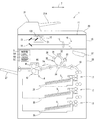
図1に示される画像形成装置1は、プリンター、複写機、ファクシミリ等の各機能を備えた画像形成装置である。この画像形成装置1は、入力された画像データに基づいてトナー等の現像剤を用いて印刷用紙S(本発明のシートの一例)に画像を印刷する。画像形成装置1は、原稿の画像を読み取る画像読取部10を上部に備え、電子写真方式の画像形成部22を下部に備える。なお、本実施形態では、本発明の画像形成装置の一例として画像形成装置1を例示して説明するが、これに限られず、例えばプリンター、ファクシミリ装置、複写機も本発明の画像形成装置に該当する。
An image forming apparatus 1 shown in FIG. 1 is an image forming apparatus having various functions such as a printer, a copying machine, and a facsimile. The image forming apparatus 1 prints an image on the printing paper S (an example of the sheet of the present invention) using a developer such as toner based on the input image data. The image forming apparatus 1 includes an
[画像読取部10]
画像読取部10は、原稿載置面を構成するコンタクトガラス11と、コンタクトガラス11に対して開閉する原稿カバー20とを備える。画像形成装置1が複写機として機能する場合は、コンタクトガラス11に原稿がセットされて原稿カバー20が閉じられた後に、不図示の操作パネルからコピー開始指示が入力されると、画像読取部10による読取動作が開始されて、原稿の画像データが読み取られる。画像読取部10の内部には、LED光源121及びミラー122を備えた読取ユニット12、ミラー13、ミラー14、光学レンズ15、及びCCD16等の光学系機器が設けられている。モーター等によって読取ユニット12が副走査方向7へ移動され、その移動中にLED光源121からコンタクトガラス11へ向けて照射される光が副走査方向7へ走査され、この反射光がCCD16に入力される。これにより、コンタクトガラス11上の原稿の画像が読み取られる。
[Image Reading Unit 10]
The
なお、原稿カバー20には、ADF21が設けられている。ADF21は、原稿セット部21Aにセットされた複数の原稿を複数の搬送ローラー(不図示)によって順次搬送して、コンタクトガラス11上に定められた読取位置を副走査方向7の右向きへ通過するように原稿を移動させる。ADF21による原稿の移動時は、前記読取位置の下方に読取ユニット12が配置され、この位置で読取ユニット12によって移動中の原稿の画像が読み取られる。
The document cover 20 is provided with an
[画像形成部22]
画像形成部22は、画像読取部10で読み取られた画像データ、又は外部の情報処理装置から入力された画像データに基づいて画像形成処理(印刷処理)を実行する電子写真方式の画像形成部である。画像形成部22は、図1に示されるように、給紙カセット25、感光体ドラム31、帯電装置32、現像装置33、転写装置34、クリーニングブレード35、除電装置36、定着装置4、露光装置37、及び用紙排出部27等を備えている。
[Image forming unit 22]
The
図1に示されるように、給紙カセット25は、画像形成部22の下方に設けられている。本実施形態では3つの給紙カセット25が上下方向に配置されている。各給紙カセット25には、複数のシート状の印刷用紙S(シート)が積層された状態で収容される。給紙カセット25に収容された印刷用紙Sは、給送ローラー等を含む給送機構17によって一枚ずつ取り出された後に、画像形成部22の内部の搬送路18を通って転写装置34へ向けて搬送される。
As shown in FIG. 1, the
感光体ドラム31は、ドラム形状に形成された回転体であり、画像形成部22の内部のフレーム等に回転可能に支持されている。感光体ドラム31は、図示しないモーター等の駆動源から駆動力が伝達されて、図1における時計回転方向へ回転駆動される。
The
感光体ドラム31の外周面に沿うように、帯電装置32、現像装置33、転写装置34、クリーニングブレード35、及び除電装置36の順に配置されている。
A charging
帯電装置32は、感光体ドラム31の上方において、感光体ドラム31の外周面に対向するように設けられている。帯電装置32は、画像形成時に感光体ドラム31の外周面の感光層を所定の極性の表面電位となるように一様に帯電させる。現像装置33は、帯電装置32よりも感光体ドラム31の回転方向の下流側に設けられている。現像装置33は、表面電位よりも低いバイアス電圧が印加された現像ローラーを有している。現像ローラーによって、図示しないトナーコンテナから運ばれたトナーが感光体ドラム31へ供給される。
The charging
露光装置37は、帯電装置32と現像装置33との間から感光体ドラム31へ向けてレーザービームを照射して、感光体ドラム31の外周面を露光する。これにより、レーザービームに含まれる画像情報に応じた静電潜像が感光体ドラム31の外周面に形成される。感光体ドラム31の外周面にレーザービームが照射されると、その照射された露光部分の電位が放電し、その露光部分によって静電潜像が形成される。現像装置33によって感光体ドラム31にトナーが供給されると、そのトナーは、静電潜像とバイアス電圧との電位差による静電気力によって静電潜像に付着することで、感光体ドラム31の外周面にトナー像が形成される。
The
転写装置34は、現像装置33よりも感光体ドラム31の回転方向の下流側に設けられている。転写装置34は、感光体ドラム31の下方において、感光体ドラム31の外周面に対向するように設けられている。転写装置34は、感光体ドラム31の外周面に接触して回転する転写ローラーを有している。画像形成時に感光体ドラム31と転写ローラーとのニップ部に印刷用紙Sが挟持された状態になると、感光体ドラム31の外周面に形成されたトナー像が印刷用紙Sの表面に付着(転写)する。
The
クリーニングブレード35は、転写装置34よりも感光体ドラム31の回転方向の下流側に設けられている。クリーニングブレード35は、用紙に転写されずに感光体ドラム31の外周面上に残存したトナーを除去するものであり、シリコンゴム等によって形成されている。
The
除電装置36は、クリーニングブレード35よりも感光体ドラム31の回転方向の下流側に設けられている。除電装置36は、感光体ドラム31の感光層に残った電荷を除去する。
The
[定着装置4]
図1に示されるように、定着装置4は、転写装置34よりも印刷用紙Sの搬送方向7Aの下流側に設けられている。定着装置4は、印刷用紙Sに転写されたトナー像をその印刷用紙Sに定着させる。定着装置4を通過した印刷用紙Sは、用紙排出部27へ排出される。図2及び図3に示されるように、定着装置4は、定着ローラー41(本発明の熱伝達体の一例)、加圧ローラー42(本発明の加圧ローラーの一例)、温度センサー44(本発明の温度検知部の一例)、及び駆動モーター45(本発明の駆動部の一例)等を備えている。
[Fixing device 4]
As shown in FIG. 1, the fixing
定着ローラー41は、トナー像が転写された印刷用紙Sに熱を伝達するものであり、回転可能に支持されている。定着ローラー41は、筒状のステンレス鋼等の金属によってローラー形状に形成されている。そのため、定着ローラー41は、熱容量が小さく比較的短時間でその温度が昇温される。
The fixing
ハロゲンランプ43(本発明の加熱部の一例)は、定着ローラー41の内部に設けられており、定着ローラー41を内側から加熱する。ハロゲンランプ43は、タングステン等の抵抗発熱体によって定着ローラー41を内側から加熱する。ハロゲンランプ43は、点灯(稼働)されると定着ローラー41を加熱し、消灯(非稼働又は停止)されると定着ローラー41に熱を与えない。ハロゲンランプ43が消灯されて熱が伝達されなくなると、定着ローラー41は、周囲の空気により熱が奪われて室温まで徐々に冷やされる。なお、本発明の加熱部は、ハロゲンランプ43に限らず、セラミックヒーター等でもよい。
The halogen lamp 43 (an example of the heating unit of the present invention) is provided inside the fixing
加圧ローラー42は、定着ローラー41に対向する位置に定着ローラー41に圧接して配置されている。定着ローラー41と加圧ローラー42との圧接部分である定着ニップ部48を通過する印刷用紙Sに、加圧ローラー42は圧力を加えてトナー像を印刷用紙Sに定着させる。加圧ローラー42は、ステンレス鋼等の円筒型の芯金と、芯金上に形成される例えばシリコン樹脂の弾性層と、弾性層の表面を覆うフッ素樹脂等からなる離型層と、を備える。これによって、加圧ローラー42は、適正なニップ幅及び適正な圧力で印刷用紙Sを加圧することができる。また、熱容量が大きい材質であるシリコン樹脂等で形成される加圧ローラー42は、金属等で形成される定着ローラー41よりも熱を保持しやすい。
The
駆動モーター45は、加圧ローラー42に駆動力を付与し、加圧ローラー42を回転させる。定着ローラー41は、定着ニップ部48で圧接する加圧ローラー42から駆動力が伝達されて従動する。なお、駆動モーター45は、定着ローラー41に駆動力を付与し、定着ローラー41を回転させ、加圧ローラー42を従動させるものや、定着ローラー41及び加圧ローラー42の双方に駆動力を付与して、双方を回転駆動するものでもよい。
The
温度センサー44は、定着ローラー41の表面温度を検知して、検知温度(本発明の検知結果の一例)を制御部5に出力する。温度センサー44は、温度の上昇に伴って抵抗が比例的に減少するNTCサーミスターを用いている。温度センサー44の検出部分は、定着ローラー41による印刷用紙Sの搬送方向7Aの上流側に配置されている。
The
[制御部5の構成]
制御部5は、画像形成装置1を統括制御する。図1に示されるように、制御部5は、CPU5A、ROM5B、及びRAM5C等を主な構成要素とするマイクロコンピュータとして構成されている。なお、制御部5は、集積回路(ASIC、DSP)等の電子回路で構成されたものであってもよい。
[Configuration of Control Unit 5]
The
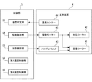
制御部5は、画像形成装置1の内部において、画像読取部10、ADF21、画像形成部22、及び給送機構17等に接続されており、これらの構成要素を制御する。また、図3に示されるように、制御部5は、画像形成部22に含まれる定着装置4を構成する各要素、具体的には、温度センサー44、駆動モーター45、及びハロゲンランプ43等にも接続されている。ROM5Bには、画像形成処理を実行するためのプログラムが記憶されている。CPU5Aは、ROM5B内の制御プログラムを実行することによって、制御部5に接続された各要素を制御して、印刷用紙Sに画像を印刷する。
The
本実施形態では、制御部5のROM5Bに、後述する温度制御処理を実行するためのプログラム等が記憶されている。CPU5Aは、このプログラムを実行することにより、前記温度制御処理を実行する。また、CPU5Aが前記プログラムを実行することにより、前記温度制御処理において、制御部5は、温度判定部51、駆動制御部52、加熱制御部53、第1温度制御部54(本発明の第1温度制御部の一例)、及び第2温度制御部55(本発明の第2温度制御部の一例)として機能する(図3参照)。
In the present embodiment, a program for executing a temperature control process described later is stored in the
また、ROM5Bには、前記プログラムの他に、前記温度制御処理に用いられる温度値、回転時間等が記憶されている。例えば、温度判定部51で比較対象となる定着温度T1(本発明の第1温度の一例)、待機温度T2(本発明の第2温度の一例)、モーター回転開始温度T3(本発明の第3温度の一例)等の設定値がROM5Bに記憶されている。なお、定着温度T1は、トナー像が印刷用紙Sに定着可能な温度であり、例えば180度から200度である。待機温度T2は、非加熱時の温度から定着温度T1の範囲内で任意に設定された温度であり、画像形成指示等が入力された場合に、ハロゲンランプ43によって定着ローラー41を画像形成のために定着温度T1まで迅速に加熱することが可能な非画像形成時の温度であり、例えば50度である。モーター回転開始温度T3は、定着温度T1よりも低く待機温度T2以上の予め定められた温度であり、例えば51度である。また、駆動制御部52が定着ローラー41及び加圧ローラー42を回転駆動させるために必要な通電時間等の設置値がROM5Bに記憶されている。また、加熱制御部53がハロゲンランプ43を点灯させる点灯時間等の設定値がROM5Bに記憶されている。なお、RAM5Cには、温度判定部51が判定した温度、駆動制御部52が稼働している稼働時間、及び加熱制御部53がハロゲンランプ43を点灯している点灯時間等が一時的に記憶される。
In addition to the program, the
温度判定部51は、温度センサー44の検知温度を定着温度T1、待機温度T2、及びモーター回転開始温度T3と比較して、検知温度が定着温度T1、待機温度T2、及びモーター回転開始温度T3よりも高いか又は低いかを判定する。なお、温度判定部51による具体的な温度判定については後述する。
The
駆動制御部52は、定着ローラー41及び加圧ローラー42を回転駆動及び停止させる。駆動制御部52は、温度判定部51の判定結果がモーター回転開始温度T3以下になったと判定した場合に、少なくとも定着ローラー41を1回転させる。駆動制御部52が、定着ローラー41及び加圧ローラー42を回転駆動させる回数及び時間は、予め定めておくことも可能である。なお、駆動制御部52による具体的な駆動制御については後述する。
The
加熱制御部53は、温度判定部51による温度センサー44の検知温度が待機温度T2より高いと判定された場合には、ハロゲンランプ43を消灯する。加熱制御部53は、温度判定部51により温度センサー44の検知温度が待機温度T2より高くないと判定された場合には、ハロゲンランプ43を点灯し、定着ローラー41が待機温度T2以下にならないように維持する。なお、加熱制御部53による具体的な加熱制御については後述する。
When it is determined that the temperature detected by the
第1温度制御部54は、画像形成時に定着ローラー41を定着温度T1に維持するように加熱制御部53にハロゲンランプ43の点灯及び消灯を制御させる画像形成モードを実行する。また、第1温度制御部54は、非画像形成時に定着ローラー41を待機温度T2に維持するように加熱制御部53にハロゲンランプ43の点灯及び消灯を制御させる省電力モードを実行する。第1温度制御部54は、前記画像形成モードと前記省電力モードとのいずれかのモードで定着装置4の温度を制御する。
The first
第2温度制御部55は、第1温度制御部54が前記画像形成モードから前記省電力モードに移行するときに、温度判定部51により温度センサー44の検知温度がモーター回転開始温度T3以下であると判定された場合に、駆動制御部52によって駆動モーター45に定着ローラー41を少なくとも1回転させる。その間、加熱制御部53はハロゲンランプ43を消灯(停止)させた状態を維持させる。また、第2温度制御部55は、駆動制御部52によって駆動モーター45に定着ローラー41を少なくとも1回転させた後に、温度判定部51により温度センサー44の検知温度が待機温度T2よりも低くないと判定された場合に、駆動制御部52に駆動モーター45の回転駆動を停止させる。なお、第2温度制御部55による具体的な温度制御については後述する。
When the first
[温度制御処理]
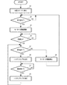
次に、図4のフローチャートを参照して、制御部5によって実行される温度制御処理の手順とともに、本発明の定着装置の温度制御方法及びプログラムについて説明する。図中のS1、S2、・・・は処理手順(ステップ)の番号を表している。各ステップにおける処理は、制御部5によって、より詳細にはCPU5AがROM5B内のプログラムを実行することによって行われる。ここに、前記温度制御処理を実行するときの制御部5が本発明に係る第2温度制御部の一例である。
[Temperature control processing]
Next, the temperature control method and program for the fixing device of the present invention will be described with reference to the flowchart of FIG. In the figure, S1, S2,... Represent processing procedure (step) numbers. Processing in each step is performed by the
以下の説明においては、ステップS1の時点で、画像形成装置1が印刷可能な前記画像形成モードから前記省電力モードに移行するものとする。言い換えると、設定された所定の省電力モード移行時間内に、ファクスの送受信やパソコンからの印刷、コピー等が行なわれなかったため、画像形成装置1は、前記画像形成モードから前記省電力モードに移行するものとする。なお、制御部5が前記温度制御処理を実行している最中に画像を形成する指示が入力されると、制御部5は、前記温度制御処理を中断して、画像形成装置1を前記省電力モードから前記画像形成モードに移行させる。
In the following description, at the time of step S1, it is assumed that the image forming apparatus 1 shifts from the image forming mode in which printing is possible to the power saving mode. In other words, because the transmission / reception of a fax, printing or copying from a personal computer, or the like has not been performed within a set predetermined power saving mode transition time, the image forming apparatus 1 shifts from the image forming mode to the power saving mode. It shall be. When an instruction to form an image is input while the
(ステップS1)
まず、ステップS1では、制御部5は、画像形成装置1に対して所定の前記省電力モード移行時間内に画像形成の指示が無かったため、画像形成装置1を前記画像形成モードから前記省電力モードに移行する。制御部5は、ハロゲンランプ43を消灯し、駆動モーター45を停止して定着ローラー41及び加圧ローラー42の回転駆動を停止させる。これによって、定着ローラー41の表面温度は、定着温度T1から徐々に低くなる。
(Step S1)
First, in step S1, the
(ステップS2)
ステップS2では、制御部5は、温度センサー44の検知温度である定着ローラー41の表面温度を取得し、取得した定着ローラー41の表面温度がモーター回転開始温度T3以下になったか否かを判定する。ステップS2において、制御部5は、モーター回転開始温度T3以下になるまで待ち続ける(S2のNO側)。一方、モーター回転開始温度T3以下になったと判定すると、制御部5は、処理をステップS3に移行させる(S2のYES側)。ここで、ステップS1及びステップS2は、本発明の第1ステップの一例である。
(Step S2)
In step S <b> 2, the
(ステップS3)
ステップS3では、制御部5は、駆動モーター45を駆動させて定着ローラー41及び加圧ローラー42を回転駆動させる。定着ローラー41の熱容量が加圧ローラー42の熱容量よりも小さいため、前記省電力モードに移行後の一定時間において、定着ローラー41の表面温度は、加圧ローラー42の表面温度よりも早く低下する。定着ローラー41の表面温度は、モーター回転開始温度T3よりも低いが、加圧ローラー42の表面温度は、モーター回転開始温度T3よりも高い場合がある。そのため、定着ローラー41は、少なくとも1回転させられると、定着ニップ部48で圧接する加圧ローラー42から定着ローラー41へ熱が伝搬し、定着ローラー41の全外周表面の温度が上昇する。なお、ステップS3を実行する制御部5は、ハロゲンランプ43を消灯し続ける。
(Step S3)
In step S <b> 3, the
(ステップS4)
ステップS4では、制御部5は、駆動モーター45によって回転駆動させられた定着ローラー41の回転数が、予め定められた設定回転数H1になったか否かを判定する。ステップS4において、制御部5は、設定回転数H1になるまで待ち続ける(S4のNO側)。一方、設定回転数H1になったと判定すると、制御部5は、処理をステップS5に移行させる(S4のYES側)。なお、設定回転数H1は、加圧ローラー42から定着ローラー41に熱を伝えるために必要な回転数であり、定着ローラー41及び加圧ローラー42の材質、厚さ、大きさ、回転速度等により予め定められる。設定回転数H1は、少なくとも定着ローラー41が1回転するように設定されていれば、後述するステップS9で停止するまで回転駆動し続けるものでもよい。ここで、ステップS3及びステップS4は、本発明の第2ステップの一例である。
(Step S4)
In step S <b> 4, the
(ステップS5)
ステップS5では、制御部5は、温度センサー44の検知温度である定着ローラー41の表面温度を取得し、取得した定着ローラー41の表面温度が待機温度T2より低いか否かを判定する。ステップS5において、制御部5は、定着ローラー41の表面温度が待機温度T2より低くないと判定すると、制御部5は、処理をステップS9に移行させる(S5のNO側)。一方、待機温度T2より低いと判定すると、制御部5は、処理をステップS6に移行させる(S5のYES側)。
(Step S5)
In step S <b> 5, the
(ステップS6)
ステップS6では、制御部5は、ハロゲンランプ43を点灯させる。先のステップS3において、制御部5は、駆動モーター45によって定着ローラー41及び加圧ローラー42を回転駆動させているため、ハロゲンランプ43から放射される熱は、定着ローラー41の表面に均等に伝わり、定着ニップ部48を介して加圧ローラー42にも熱が伝わる。
(Step S6)
In step S <b> 6, the
(ステップS7)
ステップS7では、制御部5は、温度センサー44の検知温度である定着ローラー41の表面温度を取得し、取得した定着ローラー41の表面温度が待機温度T2より高くなったか否かを判定する。ステップS7において、制御部5は、定着ローラー41の表面温度が待機温度T2より高くなるまで待ち続ける(S7のNO側)。一方、待機温度T2より高くなったと判定すると、制御部5は、処理をステップS8に移行させる(S7のYES側)。これによって、制御部5は、定着ローラー41の表面温度が、待機温度T2より低くなることを防止して、画像を形成する指示が入力されたことに応じて、直ちに画像形成装置1が前記省電力モードから前記画像形成モードに移行できる状態を維持する。
(Step S7)
In step S <b> 7, the
(ステップS8)
ステップS8では、制御部5は、ハロゲンランプ43を消灯させる。制御部5は、定着ローラー41の表面温度が待機温度T2より高くなることを防止して、定着ローラー41の表面温度を維持するために余分な電力が消費されることを防ぐ。ステップS8を実行した後に、制御部5は、処理をステップS5に移行する。なお、ステップS8を経てステップS5に移行された場合、定着ローラー41の表面温度は待機温度T2より高いため(S5のNO側)、ステップS5において、制御部5は、処理をステップS9へ移行する。
(Step S8)
In step S8, the
(ステップS9)
ステップS5において、定着ローラー41の表面温度が待機温度T2より低くないと判定すると(S5のNO側)、ステップS9において、制御部5は、駆動モーター45の駆動を停止することで、定着ローラー41及び加圧ローラー42の回転駆動を停止させる。この場合、定着ローラー41の表面温度が待機温度T2以上であるため、制御部5は、定着ローラー41及び加圧ローラー42を回転駆動させる必要がない。制御部5は、画像形成装置1の電力消費を抑えるために、定着ローラー41及び加圧ローラー42の回転駆動を停止する。ステップS9を実行した制御部5は、処理をステップS2に移行する。
(Step S9)
If it is determined in step S5 that the surface temperature of the fixing
制御部5は、画像を形成する指示が入力されるまで、ステップS2乃至ステップS9の処理を繰り返し実行する。ステップS2乃至ステップS5及びステップS9の処理を実行する制御部5が、本発明の第2温度制御部55の一例に相当する。これらの処理の場合に、制御部5は、ハロゲンランプ43を点灯させずに、駆動モーター45によって、定着ローラー41及び加圧ローラー42を回転駆動させて、定着ローラー41の表面温度が待機温度T2に低下するまでの時間を長くする。
The
上述したように、本実施形態では、制御部5による前記温度制御処理の際に、定着ローラー41の表面温度は、モーター回転開始温度T3よりも低いが、加圧ローラー42の表面温度は、モーター回転開始温度T3よりも高い場合がある。この場合に、制御部5が、駆動モーター45によって定着ローラー41を少なくとも1回転させると、加圧ローラー42から定着ローラー41へ熱が伝搬し、定着ローラー41の表面温度が上昇する。これによって、制御部5は、ハロゲンランプ43を点灯させて電力を消費することなく、定着ローラー41の表面温度が待機温度T2に低下するまでの時間を長くすることができる。
As described above, in the present embodiment, during the temperature control process by the
同様に、制御部5による前記温度制御処理の際に、定着ローラー41の表面温度は、待機温度T2よりも低いが、加圧ローラー42の表面温度は、待機温度T2よりも高い場合がある。この場合に、制御部5が、駆動モーター45によって定着ローラー41を少なくとも1回転させると、加圧ローラー42から定着ローラー41へ熱が伝搬し、定着ローラー41の表面温度が上昇する。これによって、制御部5は、ハロゲンランプ43を点灯せて電力を消費することなく、定着ローラー41の表面温度を待機温度T2以上に維持することができる。
Similarly, during the temperature control process by the
[温度制御処理の他の例]
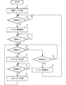
上述した実施形態の説明では、温度センサー44の検知温度が待機温度T2であることを条件に、制御部5は、駆動モーター45の回転駆動を停止させる場合について説明したが、この例に限るものではない。例えば、制御部5は、温度センサー44の検知温度が予め定められたモーター停止温度T4(本発明の第4温度の一例)になった場合に、制御部5は、駆動モーター45の回転駆動を停止させることが考えられる。
[Other examples of temperature control processing]
In the description of the above-described embodiment, the
実施形態と異なり、制御部5が、温度センサー44の検知温度が予め定められたモーター停止温度T4以上であるか否かを判定する処理が必要である。その他の部分は実施形態の構成及び処理と共通するため、ここでは、異なる部分だけ説明して、共通する部分の説明は省略する。
Unlike the embodiment, the
実施形態の変形例では、温度判定部51は、温度センサー44の検知温度をモーター停止温度T4と比較して、検知温度がモーター停止温度T4以上か否かを判定する。なお、モーター停止温度T4は、定着温度T1よりも低くモーター回転開始温度T3以上の温度であり、例えば55度である。
In the modification of the embodiment, the
(ステップS11)
前記温度制御処理のステップS5において、待機温度T2より低くないと判定すると(S5のNO側)、ステップS11において、制御部5は、温度センサー44から検知温度である定着ローラー41の表面温度を取得し、取得した定着ローラー41の表面温度がモーター停止温度T4以上か否かを判定する。ステップS11において、制御部5は、モーター停止温度T4以上でないと判定すると、処理をステップS5に移行する(S11のNO側)。そのため、制御部5は、定着ローラー41の表面温度が待機温度T2以上でありモーター停止温度T4未満の間、駆動モーター45によって、定着ローラー41及び加圧ローラー42を回転駆動させる。一方、モーター停止温度T4以上であると判定すると、制御部5は、処理をステップS9に移行する(S11のYES側)。続く、ステップS9において、制御部5は、駆動モーター45の駆動を停止することで、定着ローラー41及び加圧ローラー42を停止させる。
(Step S11)
If it is determined in step S5 of the temperature control process that the temperature is not lower than the standby temperature T2 (NO side of S5), in step S11, the
このように、モーター停止温度T4をモーター回転開始温度T3よりも高い温度にすることによって、駆動モーター45は、待機温度T2より高くモーター停止温度T4未満の間では、駆動し続けることになる。仮に、モーター停止温度T4を待機温度T2に近い温度に設定された場合に、定着ローラー41の表面温度が待機温度T2付近になると、制御部5は、駆動モーター45の駆動と停止とを繰り返し実行する可能性がある。一般的に、駆動モーター45は、一定速度で回転駆動し続けている定常回転時の消費電力よりも駆動開始時の電力消費の方が大きくなる特性がある。そのため、駆動モーター45の停止時間が短い場合には、駆動モーター45が回転駆動し続けた方が消費される電力が低い。これによって、制御部5は、少ない電力によって定着ローラー41の表面温度が待機温度T2に低下するまでの時間を長くすることができる。
Thus, by setting the motor stop temperature T4 to a temperature higher than the motor rotation start temperature T3, the
[実施形態の第1変形例]
上述の実施形態では、定着ローラー41の内部にハロゲンランプ43が設けられた場合について説明したが、この例に限るものではない。例えば、図6に示されるように、定着装置4のハロゲンランプ43の代わりに、定着装置4Bには、ローラー形状に形成された定着ローラー41の表面を誘導加熱するIHコイル43Bを定着ローラー41の外側に設けられている。一般的に、IHコイル43Bは、ハロゲンランプ43よりも定着ローラー41を加熱する時間が短く、消費電力が小さいため、画像形成装置1の消費電力を少なくすることができる。
[First Modification of Embodiment]
In the above-described embodiment, the case where the
[実施形態の第2変形例]
また、上述の実施形態では、定着ローラー41の内部にハロゲンランプ43が設けられた場合について説明したが、この例に限るものではない。例えば、図7に示されるように、定着装置4Cは、定着装置4の定着ローラー41及びハロゲンランプ43の代わりに、加熱ローラー47、ハロゲンランプ43C、定着ベルト46(本発明の熱伝達体の一例)、及び加圧パッド41C(本発明の押圧部の一例)を備える。ハロゲンランプ43Cは、加熱ローラー47の内部に設けられており、フィラメント等の抵抗発熱体によって加熱ローラー47を内側から加熱する。加熱ローラー47は、ハロゲンランプ43Cによって加熱された熱を定着ベルト46に伝達する。定着ベルト46は、回動可能に支持された無端状のベルトであり、加熱ローラー47と加圧パッド41Cにより懸架されている。定着ベルト46は、加熱ローラー47を介してハロゲンランプ43Cにより加熱される。加圧パッド41Cは、定着ベルト46に内接し、定着ベルト46を加圧ローラー42に押圧する。なお、加圧ローラー42は、定着ベルト46の外周面に対向して配置されている。画像形成装置1がカラーの画像を形成するものであり、各色の定着装置4Cが定着ベルト46によって搬送路上に配置されている場合に適した構成である。なお、第2適用例の加熱部は、ハロゲンランプ43Cの代わりに誘導加熱により定着ベルト46を直接加熱するものでもよい。また、第2適用例の前記加熱部は、定着ベルト46を外部から加熱するものでも、内部から加熱するものでもよい。
[Second Modification of Embodiment]
In the above-described embodiment, the case where the
[実施形態の第3変形例]
また、上述の実施形態では、定着ローラー41の内部にハロゲンランプ43が設けられた場合について説明したが、この例に限るものではない。例えば、図8に示されるように、定着装置4Dは、定着装置4の定着ローラー41及びハロゲンランプ43の代わりに、IHコイル43D、定着ベルト46、及びプーリー41D(本発明のプーリーの一例)を備える。IHコイル43Dは、誘導加熱によって定着ベルト46の表面を加熱する。定着ベルト46は、回動可能に支持された無端状のベルトであり、ローラー47Dと加圧パッド41Cにより懸架されている。プーリー41Dは、定着ベルト46に内接し、定着ベルト46を加圧ローラー42に押圧しながら回転駆動する。なお、加圧ローラー42は、定着ベルト46の外周面に対向して配置されている。画像形成装置1がカラーの画像を形成するものであり、各色の定着装置4Dが定着ベルト46によって搬送路上に配置されている場合に適した構成である。なお、第3適用例の加熱部は、IHコイル43Dの代わりに、ハロゲンランプにより定着ベルト46を加熱するものでもよい。
[Third Modification of Embodiment]
In the above-described embodiment, the case where the
なお、前記実施形態の前記温度制御処理及び実施形態の他の一例の前記温度制御処理では、制御部5は、ステップS3において駆動モーター45の駆動を開始させ、ステップS9において駆動モーター45の駆動を停止させる制御をする場合について説明したがこの場合に限るものではない。例えば、制御部5は、ステップS4において、定着ローラー41の回転数が設定回転数H1になった場合に、駆動モーター45の駆動を停止させるものでもよい。
In the temperature control process of the embodiment and the temperature control process of another example of the embodiment, the
1:画像形成装置
4:定着装置
5:制御部
5A:CPU
5B:ROM
5C:RAM
41:定着ローラー
42:加圧ローラー
43:ハロゲンランプ
44:温度センサー
45:駆動モーター
48:定着ニップ部
51:温度判定部
52:駆動制御部
53:加熱制御部
54:第1温度制御部
55:第2温度制御部
1: Image forming device 4: Fixing device 5:
5B: ROM
5C: RAM
41: fixing roller 42: pressure roller 43: halogen lamp 44: temperature sensor 45: drive motor 48: fixing nip 51: temperature determination unit 52: drive control unit 53: heating control unit 54: first temperature control unit 55: Second temperature controller
Claims (5)
前記熱伝達体を加熱する加熱部と、
前記熱伝達体よりも熱容量が大きい材質で形成され、前記熱伝達体に圧接して圧接部分を形成するとともに前記圧接部分を通過する前記シートに圧力を加える加圧ローラーと、
前記熱伝達体及び前記加圧ローラーの何れか一方又は双方を回転駆動する駆動部と、
前記熱伝達体の表面温度を検知する温度検知部と、
画像形成時に前記トナー像が前記シートに定着可能な第1温度に前記熱伝達体を維持するように前記加熱部を制御する画像形成モードと非画像形成時に前記第1温度よりも低い第2温度に前記熱伝達体を維持するように前記加熱部を制御する省電力モードとのいずれかのモードで前記熱伝達体の温度を制御する第1温度制御部と、
前記第1温度制御部が前記画像形成モードから前記省電力モードに移行するときに、前記温度検知部の検知した温度が前記第1温度よりも低く前記第2温度以上の予め定められた第3温度以下になった場合に、前記加熱部を停止させた状態で前記駆動部によって前記熱伝達体を少なくとも1回転させる第2温度制御部と、
を備えた画像形成装置。 A heat transfer body rotatably supported to transfer heat to the sheet on which the toner image is transferred;
A heating unit for heating the heat transfer body;
A pressure roller that is formed of a material having a larger heat capacity than the heat transfer body, presses the heat transfer body to form a pressure contact portion, and applies pressure to the sheet passing through the pressure contact portion;
A drive unit that rotationally drives either one or both of the heat transfer body and the pressure roller;
A temperature detector for detecting the surface temperature of the heat transfer body;
An image forming mode in which the heating unit is controlled to maintain the heat transfer body at a first temperature at which the toner image can be fixed to the sheet during image formation, and a second temperature lower than the first temperature during non-image formation. A first temperature control unit for controlling the temperature of the heat transfer body in any of a power saving mode for controlling the heating unit to maintain the heat transfer body;
When the first temperature control unit shifts from the image forming mode to the power saving mode, a temperature detected by the temperature detection unit is lower than the first temperature and is equal to or higher than the second temperature. A second temperature control unit for rotating the heat transfer body at least once by the driving unit in a state where the heating unit is stopped when the temperature is equal to or lower than a temperature;
An image forming apparatus.
前記熱伝達体よりも熱容量が大きい材質で形成され、前記熱伝達体に圧接して圧接部分を形成するとともに前記圧接部分を通過する前記シートに圧力を加える加圧ローラーと、
を備える定着装置の温度制御方法であって、
前記トナー像が前記シートに定着可能な第1温度に前記熱伝達体の温度を維持する画像形成モードから前記第1温度よりも低い第2温度に前記熱伝達体の温度を維持する省電力モードに移行するときに、前記熱伝達体の表面温度を検知する温度検知部の検知した温度が前記第1温度よりも低く前記第2温度以上の予め定められた第3温度以下になったか否かを判定する第1ステップと、
前記第1ステップによって前記検知した温度が前記第3温度以下になったと判定された場合に、前記加熱部を停止させた状態で前記熱伝達体を少なくとも1回転させる第2ステップと、
を含む定着装置の温度制御方法。 A heat transfer body rotatably supported to transfer heat to the sheet to which the toner image is transferred by being heated by the heating unit;
A pressure roller that is formed of a material having a larger heat capacity than the heat transfer body, presses the heat transfer body to form a pressure contact portion, and applies pressure to the sheet passing through the pressure contact portion;
A temperature control method for a fixing device comprising:
A power saving mode in which the temperature of the heat transfer body is maintained at a second temperature lower than the first temperature from an image forming mode in which the temperature of the heat transfer body is maintained at a first temperature at which the toner image can be fixed to the sheet. Whether or not the temperature detected by the temperature detection unit that detects the surface temperature of the heat transfer body is lower than the first temperature and lower than a predetermined third temperature that is equal to or higher than the second temperature. A first step of determining
A second step of rotating the heat transfer body at least once in a state where the heating unit is stopped when it is determined that the detected temperature is equal to or lower than the third temperature in the first step;
A temperature control method for a fixing device including:
前記熱伝達体よりも熱容量が大きい材質で形成され、前記熱伝達体に圧接して圧接部分を形成するとともに前記圧接部分を通過する前記シートに圧力を加える加圧ローラーと、
前記熱伝達体及び前記加圧ローラーの何れか一方又は双方を回転駆動する駆動部と、
前記熱伝達体の表面温度を検知する温度検知部と、
を備える画像形成装置を制御するコンピューターに、
前記トナー像が前記シートに定着可能な第1温度に前記熱伝達体の温度を維持する画像形成モードから前記第1温度よりも低い第2温度に前記熱伝達体の温度を維持する省電力モードに移行するときに、前記温度検知部の検知した温度が前記第1温度よりも低く前記第2温度以上の予め定められた第3温度以下になったか否かを判定する第1ステップと、
前記第1ステップによって前記検知した温度が前記第3温度以下になったと判定された場合に、前記加熱部を停止させた状態で前記駆動部によって前記熱伝達体を少なくとも1回転させる第2ステップと、
を実行させるためのプログラム。 A heat transfer body rotatably supported to transfer heat to the sheet to which the toner image is transferred by being heated by the heating unit;
A pressure roller that is formed of a material having a larger heat capacity than the heat transfer body, presses the heat transfer body to form a pressure contact portion, and applies pressure to the sheet passing through the pressure contact portion;
A drive unit that rotationally drives either one or both of the heat transfer body and the pressure roller;
A temperature detector for detecting the surface temperature of the heat transfer body;
A computer for controlling an image forming apparatus comprising:
A power saving mode in which the temperature of the heat transfer body is maintained at a second temperature lower than the first temperature from an image forming mode in which the temperature of the heat transfer body is maintained at a first temperature at which the toner image can be fixed to the sheet. A first step of determining whether or not the temperature detected by the temperature detection unit is lower than the first temperature and is equal to or lower than a predetermined third temperature that is equal to or higher than the second temperature,
A second step of rotating the heat transfer body at least once by the drive unit in a state in which the heating unit is stopped when it is determined that the detected temperature is equal to or lower than the third temperature in the first step; ,
A program for running
Priority Applications (3)
| Application Number | Priority Date | Filing Date | Title |
|---|---|---|---|
| JP2013244440A JP6025695B2 (en) | 2013-11-26 | 2013-11-26 | Image forming apparatus, temperature control method for fixing apparatus, and program |
| CN201410680051.3A CN104678731B (en) | 2013-11-26 | 2014-11-24 | Image forming apparatus and temperature control method for use in fixing device |
| US14/552,198 US9335682B2 (en) | 2013-11-26 | 2014-11-24 | Image forming apparatus, temperature control method for use in fixing device, and non-transitory recording medium |
Applications Claiming Priority (1)
| Application Number | Priority Date | Filing Date | Title |
|---|---|---|---|
| JP2013244440A JP6025695B2 (en) | 2013-11-26 | 2013-11-26 | Image forming apparatus, temperature control method for fixing apparatus, and program |
Publications (2)
| Publication Number | Publication Date |
|---|---|
| JP2015102769A true JP2015102769A (en) | 2015-06-04 |
| JP6025695B2 JP6025695B2 (en) | 2016-11-16 |
Family
ID=53182769
Family Applications (1)
| Application Number | Title | Priority Date | Filing Date |
|---|---|---|---|
| JP2013244440A Expired - Fee Related JP6025695B2 (en) | 2013-11-26 | 2013-11-26 | Image forming apparatus, temperature control method for fixing apparatus, and program |
Country Status (3)
| Country | Link |
|---|---|
| US (1) | US9335682B2 (en) |
| JP (1) | JP6025695B2 (en) |
| CN (1) | CN104678731B (en) |
Families Citing this family (4)
| Publication number | Priority date | Publication date | Assignee | Title |
|---|---|---|---|---|
| US20170060058A1 (en) * | 2015-08-31 | 2017-03-02 | K.K. Endo Seisakusho | Fixing device using stainless steel material |
| JP2017090855A (en) | 2015-11-17 | 2017-05-25 | 株式会社東芝 | Fixing device |
| JP2019043008A (en) * | 2017-08-31 | 2019-03-22 | キヤノン株式会社 | Information processing device, power control method and program in information processing device |
| JP7025869B2 (en) * | 2017-09-08 | 2022-02-25 | キヤノンファインテックニスカ株式会社 | Image forming device |
Citations (2)
| Publication number | Priority date | Publication date | Assignee | Title |
|---|---|---|---|---|
| JPH11102140A (en) * | 1997-09-25 | 1999-04-13 | Minolta Co Ltd | Fixing device |
| JP2012118409A (en) * | 2010-12-02 | 2012-06-21 | Canon Inc | Image forming apparatus |
Family Cites Families (3)
| Publication number | Priority date | Publication date | Assignee | Title |
|---|---|---|---|---|
| JPH07114292A (en) | 1993-10-20 | 1995-05-02 | Brother Ind Ltd | Electrophotographic device |
| JP3901077B2 (en) * | 2002-11-14 | 2007-04-04 | ブラザー工業株式会社 | Image forming apparatus |
| JP5206650B2 (en) | 2009-11-18 | 2013-06-12 | カシオ電子工業株式会社 | Image forming apparatus |
-
2013
- 2013-11-26 JP JP2013244440A patent/JP6025695B2/en not_active Expired - Fee Related
-
2014
- 2014-11-24 CN CN201410680051.3A patent/CN104678731B/en not_active Expired - Fee Related
- 2014-11-24 US US14/552,198 patent/US9335682B2/en active Active
Patent Citations (2)
| Publication number | Priority date | Publication date | Assignee | Title |
|---|---|---|---|---|
| JPH11102140A (en) * | 1997-09-25 | 1999-04-13 | Minolta Co Ltd | Fixing device |
| JP2012118409A (en) * | 2010-12-02 | 2012-06-21 | Canon Inc | Image forming apparatus |
Also Published As
| Publication number | Publication date |
|---|---|
| US9335682B2 (en) | 2016-05-10 |
| US20150147077A1 (en) | 2015-05-28 |
| CN104678731A (en) | 2015-06-03 |
| CN104678731B (en) | 2017-05-10 |
| JP6025695B2 (en) | 2016-11-16 |
Similar Documents
| Publication | Publication Date | Title |
|---|---|---|
| JP4999444B2 (en) | Fixing apparatus and image forming apparatus | |
| JP5257691B2 (en) | Fixing apparatus and image forming apparatus | |
| US7292801B2 (en) | Fixing device, fixing method, image forming apparatus, image forming method | |
| JP4314247B2 (en) | Image heating device | |
| JP2009265154A (en) | Image forming apparatus, printing method in image forming apparatus and computer program for functioning print processing in image forming apparatus | |
| JP2007272032A (en) | Image heating device | |
| JP6025695B2 (en) | Image forming apparatus, temperature control method for fixing apparatus, and program | |
| JP2015064548A (en) | Fixing apparatus and image forming apparatus | |
| JP4598970B2 (en) | Image forming apparatus | |
| JP2011123235A (en) | Image forming apparatus | |
| US20160252852A1 (en) | Image forming apparatus | |
| JP2009265387A (en) | Fuser | |
| JP2010102210A (en) | Image forming apparatus | |
| JP2005301070A (en) | Image forming apparatus | |
| JP2006084835A (en) | Heat fixing device, and image forming apparatus, and control method thereof | |
| JP2006171480A (en) | Image forming apparatus | |
| JP3125569B2 (en) | Image heating device | |
| JP2010002670A (en) | Image forming device | |
| JP2020197593A (en) | Image forming apparatus | |
| JP2006047398A (en) | Image forming apparatus | |
| US20230408972A1 (en) | Image forming apparatus | |
| JP2009058774A (en) | Image forming apparatus | |
| JP5239486B2 (en) | Image forming apparatus | |
| JP2023163684A (en) | Image formation device | |
| JP2006337488A (en) | Control method of fixing device, and fixing device and image forming apparatus |
Legal Events
| Date | Code | Title | Description |
|---|---|---|---|
| A621 | Written request for application examination |
Free format text: JAPANESE INTERMEDIATE CODE: A621 Effective date: 20150925 |
|
| A977 | Report on retrieval |
Free format text: JAPANESE INTERMEDIATE CODE: A971007 Effective date: 20160217 |
|
| A131 | Notification of reasons for refusal |
Free format text: JAPANESE INTERMEDIATE CODE: A131 Effective date: 20160301 |
|
| A521 | Request for written amendment filed |
Free format text: JAPANESE INTERMEDIATE CODE: A523 Effective date: 20160401 |
|
| TRDD | Decision of grant or rejection written | ||
| A01 | Written decision to grant a patent or to grant a registration (utility model) |
Free format text: JAPANESE INTERMEDIATE CODE: A01 Effective date: 20160913 |
|
| A61 | First payment of annual fees (during grant procedure) |
Free format text: JAPANESE INTERMEDIATE CODE: A61 Effective date: 20161011 |
|
| R150 | Certificate of patent or registration of utility model |
Ref document number: 6025695 Country of ref document: JP Free format text: JAPANESE INTERMEDIATE CODE: R150 |
|
| LAPS | Cancellation because of no payment of annual fees |