JP2015102190A - Vehicle control device - Google Patents
Vehicle control device Download PDFInfo
- Publication number
- JP2015102190A JP2015102190A JP2013244042A JP2013244042A JP2015102190A JP 2015102190 A JP2015102190 A JP 2015102190A JP 2013244042 A JP2013244042 A JP 2013244042A JP 2013244042 A JP2013244042 A JP 2013244042A JP 2015102190 A JP2015102190 A JP 2015102190A
- Authority
- JP
- Japan
- Prior art keywords
- vehicle
- clutch
- continuously variable
- control
- variable transmission
- Prior art date
- Legal status (The legal status is an assumption and is not a legal conclusion. Google has not performed a legal analysis and makes no representation as to the accuracy of the status listed.)
- Pending
Links
Images

Classifications
-
- Y—GENERAL TAGGING OF NEW TECHNOLOGICAL DEVELOPMENTS; GENERAL TAGGING OF CROSS-SECTIONAL TECHNOLOGIES SPANNING OVER SEVERAL SECTIONS OF THE IPC; TECHNICAL SUBJECTS COVERED BY FORMER USPC CROSS-REFERENCE ART COLLECTIONS [XRACs] AND DIGESTS
- Y02—TECHNOLOGIES OR APPLICATIONS FOR MITIGATION OR ADAPTATION AGAINST CLIMATE CHANGE
- Y02T—CLIMATE CHANGE MITIGATION TECHNOLOGIES RELATED TO TRANSPORTATION
- Y02T10/00—Road transport of goods or passengers
- Y02T10/60—Other road transportation technologies with climate change mitigation effect
Abstract
Description
本発明は、ベルト式無段変速機を備える車両の制御装置に関するものである。 The present invention relates to a control device for a vehicle including a belt type continuously variable transmission.
ベルト式無段変速機を備える車両において、その車両の前進走行中にエンジンを停止させるアイドリングストップ制御を実行する、車両の制御装置が良く知られている。例えば、特許文献1に記載されたアイドルストップ車の制御装置がそれである。特許文献1には、車両の減速中に所定のエンジン停止条件を満足した場合には、プライマリプーリに伝達されるクラッチ伝達トルクが無段変速機の伝達トルク(特にはプライマリプーリの伝達トルク)を上回らないように、プライマリプーリへの供給油圧を保持して急速な低下を防止すると共に発進クラッチの実クラッチ圧を強制的に(急速に)下げることによって、減速中アイドルストップ突入時(すなわちエンジン停止に伴う機械式オイルポンプの発生油圧の低下時)におけるベルト滑りの発生を防止又は抑制することが開示されている。 2. Description of the Related Art A vehicle control apparatus that performs idling stop control for stopping an engine while a vehicle is traveling forward is well known in a vehicle including a belt type continuously variable transmission. For example, this is the control device for an idle stop vehicle described in Patent Document 1. In Patent Document 1, when a predetermined engine stop condition is satisfied during vehicle deceleration, the clutch transmission torque transmitted to the primary pulley is the transmission torque of the continuously variable transmission (particularly, the transmission torque of the primary pulley). In order not to exceed, the supply hydraulic pressure to the primary pulley is maintained to prevent a rapid decrease, and the actual clutch pressure of the starting clutch is forcibly (rapidly) reduced, so that when the idle stop enters during deceleration (i.e., the engine stops) To prevent or suppress the occurrence of belt slip when the hydraulic pressure generated by a mechanical oil pump is reduced.
ところで、車両の前進走行中にエンジンのアイドリングストップ制御を実行しているときに、ドライバにより車両を急減速させる急減速操作が行われる可能性がある。このような急減速操作において、車速が高車速である程或いは減速操作が急である程或いは路面が低μ路である程、車輪の制動(回転低下)が急となり易く、回転慣性体による大きなイナーシャトルクが無段変速機へ入力され易くなる。このとき、入力されるイナーシャトルクが無段変速機のトルク容量(ベルト挟圧力)を上回って、ベルト滑りが発生する恐れがある。一方で、車両走行中にエンジンのアイドリングストップ制御を実行しているときには、エンジンにより回転駆動される機械式オイルポンプの代替として、電動式オイルポンプにより無段変速機等に油圧を供給することが考えられる。しかしながら、一時的に電動式オイルポンプを用いる場合には、配置スペースやコスト等を勘案すれば、機械式オイルポンプよりも吐出流量が少ない小型の電動式オイルポンプを備えることになる。その為、アイドリングストップ制御中には、依然としてベルト滑りが発生する恐れがある。尚、上述したような課題は未公知である。 By the way, when the idling stop control of the engine is being executed while the vehicle is traveling forward, there is a possibility that an abrupt deceleration operation for suddenly decelerating the vehicle by the driver may be performed. In such a sudden deceleration operation, the higher the vehicle speed, the more rapid the deceleration operation, or the lower the road surface, the easier the braking (rotation reduction) of the wheels, and the greater the speed of the rotating inertial body. The inertia torque is easily input to the continuously variable transmission. At this time, the input inertia torque exceeds the torque capacity (belt clamping pressure) of the continuously variable transmission, and belt slipping may occur. On the other hand, when engine idling stop control is being performed while the vehicle is running, hydraulic pressure can be supplied to a continuously variable transmission or the like by an electric oil pump as an alternative to a mechanical oil pump driven to rotate by the engine. Conceivable. However, when the electric oil pump is temporarily used, a small electric oil pump having a smaller discharge flow rate than the mechanical oil pump is provided in consideration of the arrangement space and cost. For this reason, belt slip may still occur during idling stop control. The above-described problem is not known.
本発明は、以上の事情を背景として為されたものであり、その目的とするところは、車両の前進走行中におけるアイドリングストップ制御の実行中に車両の急制動が行われたとしても、ベルト式無段変速機のベルト滑りを抑制乃至防止することができる車両の制御装置を提供することにある。 The present invention has been made against the background of the above circumstances, and the object of the present invention is that even if the vehicle is suddenly braked during the idling stop control while the vehicle is traveling forward, the belt type An object of the present invention is to provide a vehicle control device capable of suppressing or preventing belt slippage of a continuously variable transmission.
前記目的を達成する為の第1の発明の要旨とするところは、(a) エンジンと、ロックアップクラッチを有する流体式伝動装置と、遊星歯車装置と前記遊星歯車装置を選択的に一体回転させるクラッチ要素と前記遊星歯車装置の回転要素のうちの1つの回転要素を選択的に非回転部材に連結するブレーキ要素とを有して前記クラッチ要素の係合及び前記ブレーキ要素の解放により前進用動力伝達経路を成立させる一方で前記クラッチ要素の解放及び前記ブレーキ要素の係合により後進用動力伝達経路を成立させる前後進切換装置と、前記前後進切換装置と駆動輪との間の動力伝達経路の一部を構成するベルト式無段変速機とを備えた車両において、前記車両の前進走行中に前記エンジンを停止させるアイドリングストップ制御を実行することができる、車両の制御装置であって、(b) 前記アイドリングストップ制御の実行中に前記車両の急制動が行われた場合は、前記ロックアップクラッチ及び前記ブレーキ要素のうちの少なくとも一方を係合することにある。 The gist of the first invention for achieving the above object is that (a) an engine, a fluid transmission device having a lock-up clutch, a planetary gear device and the planetary gear device are selectively rotated integrally. A forward drive power having a clutch element and a brake element for selectively connecting one of the rotating elements of the planetary gear unit to a non-rotating member, and engaging the clutch element and releasing the brake element A forward / reverse switching device that establishes a reverse power transmission path by disengaging the clutch element and engaging the brake element while establishing a transmission path; and a power transmission path between the forward / backward switching device and the drive wheels. In a vehicle including a belt type continuously variable transmission that constitutes a part of the vehicle, it is possible to execute an idling stop control that stops the engine while the vehicle is traveling forward. A vehicle control device capable of engaging at least one of the lock-up clutch and the brake element when the vehicle is suddenly braked during execution of the idling stop control; There is.
このようにすれば、車両の急制動に合わせて、ベルト式無段変速機の入力側の回転慣性体の回転を強制的に停止させられる。或いは、車両の急制動時に、ベルト式無段変速機の入力側の回転慣性体によるイナーシャトルクを前記ロックアップクラッチ及び/又は前記ブレーキ要素に分担させられる。これにより、ベルト式無段変速機へ入力される上記イナーシャトルクを軽減することができる。よって、車両の前進走行中におけるアイドリングストップ制御の実行中に車両の急制動が行われたとしても、ベルト式無段変速機のベルト滑りを抑制乃至防止することができる。 In this way, the rotation of the rotary inertia body on the input side of the belt type continuously variable transmission can be forcibly stopped in accordance with the sudden braking of the vehicle. Alternatively, when the vehicle is suddenly braked, an inertia torque due to a rotary inertia body on the input side of the belt type continuously variable transmission is shared by the lockup clutch and / or the brake element. As a result, the inertia torque input to the belt type continuously variable transmission can be reduced. Therefore, even if the vehicle is suddenly braked during the idling stop control while the vehicle is traveling forward, belt slippage of the belt type continuously variable transmission can be suppressed or prevented.
ここで、第2の発明は、前記第1の発明に記載の車両の制御装置において、前記車両は、前記エンジンにより回転駆動される機械式オイルポンプ、及び前記機械式オイルポンプの吐出流量よりも少ない吐出流量とされた電動式オイルポンプを備え、前記アイドリングストップ制御の実行中は、前記電動式オイルポンプが吐出する油圧を元圧とする作動油により、前記ベルト式無段変速機のベルト挟圧が発生させられると共に、前記ロックアップクラッチ及び/又は前記ブレーキ要素が係合させられることにある。このようにすれば、電動式オイルポンプからの吐出油圧によって、アイドリングストップ制御の実行中にベルト式無段変速機のベルト滑りを適切に抑制乃至防止することができる。 The second aspect of the invention is the vehicle control apparatus according to the first aspect of the invention, wherein the vehicle has a mechanical oil pump that is driven to rotate by the engine, and a discharge flow rate of the mechanical oil pump. An electric oil pump having a small discharge flow rate is provided. During the idling stop control, the belt of the belt-type continuously variable transmission is clamped by hydraulic oil with a hydraulic pressure discharged from the electric oil pump as a base pressure. Pressure is generated and the lock-up clutch and / or the brake element is engaged. In this way, the belt slip of the belt-type continuously variable transmission can be appropriately suppressed or prevented by the hydraulic pressure discharged from the electric oil pump during the idling stop control.
また、第3の発明は、前記第1の発明又は第2の発明に記載の車両の制御装置において、前記アイドリングストップ制御の実行中に前記車両の走行路が低μ路であると判断された場合は、前記車両の急制動が行われた場合に係合する、前記ロックアップクラッチ及び/又は前記ブレーキ要素に対してトルク容量が生じない程度の所定油圧を供給することにある。このようにすれば、車両の急制動が行われた場合の前記ロックアップクラッチ及び/又は前記ブレーキ要素の係合時の応答性が向上させられる。 According to a third aspect of the present invention, in the vehicle control device according to the first or second aspect of the present invention, it is determined that the traveling path of the vehicle is a low μ road during the execution of the idling stop control. In this case, a predetermined hydraulic pressure is applied to the lock-up clutch and / or the brake element, which is engaged when the vehicle is suddenly braked so that no torque capacity is generated. In this way, the responsiveness when the lockup clutch and / or the brake element is engaged when the vehicle is suddenly braked is improved.
また、第4の発明は、前記第1の発明乃至第3の発明の何れか1つに記載の車両の制御装置において、前記アイドリングストップ制御において前記エンジンの停止と併せて前記クラッチ要素を解放する場合に、前記アイドリングストップ制御の実行中に前記車両の急制動が行われた場合には、前記ロックアップクラッチ及び前記ブレーキ要素のうちの少なくとも一方を係合することと併せて前記クラッチ要素を係合することにある。このようにすれば、車両の急制動に合わせて、ベルト式無段変速機の入力側の回転慣性体の回転を適切に停止させられる。或いは、車両の急制動時に、ベルト式無段変速機の入力側の回転慣性体によるイナーシャトルクを前記ロックアップクラッチ及び/又は前記ブレーキ要素に適切に分担させられる。 According to a fourth aspect of the present invention, in the vehicle control device according to any one of the first to third aspects of the invention, the idling stop control releases the clutch element together with the stop of the engine. If the vehicle is suddenly braked during the idling stop control, the clutch element is engaged together with engaging at least one of the lock-up clutch and the brake element. There is to match. In this way, the rotation of the rotary inertia body on the input side of the belt type continuously variable transmission can be appropriately stopped in accordance with the sudden braking of the vehicle. Alternatively, when the vehicle is suddenly braked, an inertia torque due to the rotary inertia body on the input side of the belt-type continuously variable transmission is appropriately assigned to the lockup clutch and / or the brake element.
本発明において、好適には、例えば前記ベルト式無段変速機は、固定シーブと可動シーブとそれら固定及び可動シーブの間の溝幅を変更する為の推力を付与する油圧アクチュエータとを各々有する入力側及び出力側のプーリと、前記入力側及び出力側のプーリの間に巻き掛けられた伝動ベルトとを備える。前記油圧アクチュエータに供給される作動油圧(プーリ圧)をそれぞれ独立に制御するように油圧制御回路が構成される。或いは、例えば前記油圧アクチュエータへの作動油の流量を制御することにより結果的にプーリ圧を生じるように油圧制御回路が構成される。このような油圧制御回路により、前記入力側及び出力側のプーリにおける推力が各々直接的に或いは間接的に(結果的に生じるように)制御されることで、伝動ベルトの滑りを防止しつつ目標の変速が実現されるように変速制御が実行される。尚、本明細書で「油圧を供給する」という場合は、「油圧を作用させ」或いは「その油圧に制御された作動油を供給する」ことを意味する。 In the present invention, for example, the belt-type continuously variable transmission preferably includes an input having a fixed sheave, a movable sheave, and a hydraulic actuator that applies a thrust for changing a groove width between the fixed sheave and the movable sheave. Side pulleys and output side pulleys, and a transmission belt wound between the input side and output side pulleys. A hydraulic control circuit is configured to independently control the operating hydraulic pressure (pulley pressure) supplied to the hydraulic actuator. Alternatively, for example, the hydraulic control circuit is configured so as to generate pulley pressure as a result of controlling the flow rate of hydraulic oil to the hydraulic actuator. By such a hydraulic control circuit, the thrust in the pulley on the input side and the output side is controlled directly or indirectly (as a result), thereby preventing the transmission belt from slipping. Shift control is executed so that the following shift is realized. In this specification, “supplying hydraulic pressure” means “applying hydraulic pressure” or “supplying hydraulic oil controlled to the hydraulic pressure”.
また、好適には、前記エンジンは、例えば内燃機関等のガソリンエンジンやディーゼルエンジン等であるが、駆動力源として、電動機等を前記エンジンと組み合わせて採用することもできる。 Preferably, the engine is, for example, a gasoline engine such as an internal combustion engine, a diesel engine, or the like, but an electric motor or the like can be used in combination with the engine as a driving force source.
以下、本発明の実施例を図面を参照しつつ詳細に説明する。 Hereinafter, embodiments of the present invention will be described in detail with reference to the drawings.
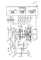
図1は、本発明が適用される車両10の概略構成を説明する図であると共に、車両10における各種制御の為の制御機能及び制御系統の要部を説明する図である。図1において、車両10は、走行用駆動力源としてのエンジン12、流体式伝動装置としてのトルクコンバータ14、前後進切換装置16、ベルト式無段変速機18(以下、無段変速機18という)、減速歯車装置20、差動歯車装置22、左右の駆動輪24などを備えている。車両10では、エンジン12から出力される動力は、トルクコンバータ14、前後進切換装置16、無段変速機18、減速歯車装置20、差動歯車装置22などを順次介して、左右の駆動輪24へ伝達される。
FIG. 1 is a diagram illustrating a schematic configuration of a
トルクコンバータ14は、エンジン12に連結されたポンプ翼車14p、及びタービン軸26を介して前後進切換装置16に連結されたタービン翼車14tを備えており、流体を介して動力伝達を行う。又、トルクコンバータ14には、ポンプ翼車14p及びタービン翼車14tの間(すなわちトルクコンバータ14の入出力回転部材間)を直結可能な公知のロックアップクラッチLU(以下、クラッチLUという)が設けられている。クラッチLUの作動状態としては、例えばクラッチLUが解放される所謂ロックアップ解放(ロックアップオフ)、クラッチLUが滑りを伴って半係合(スリップ作動)される所謂ロックアップスリップ状態(スリップ状態)、及びクラッチLUが完全係合される所謂ロックアップ状態(係合状態、ロックアップオン)の3状態に大別される。クラッチLUがロックアップオフさせられることにより、トルクコンバータ14はトルク増幅作用が得られる。又、クラッチLUがロックアップオンさせられることにより、ポンプ翼車14p及びタービン翼車14tが一体回転させられてエンジン12の動力が前後進切換装置16側へ直接的に伝達される。又、クラッチLUがスリップ作動させられることにより、車両10の駆動(パワーオン)時には所定のスリップ量でタービン軸26がエンジン12のクランク軸に対して追従回転させられる一方、車両の非駆動(パワーオフ)時には所定のスリップ量でエンジン12のクランク軸がタービン軸26に対して追従回転させられる。又、ポンプ翼車14pには、機械式オイルポンプ28が連結されている。
The
前後進切換装置16は、前進用クラッチC1及び後進用ブレーキB1とダブルピニオン型の遊星歯車装置16pとを主体として構成されている。遊星歯車装置16pのサンギヤ16sにはトルクコンバータ14のタービン軸26が一体的に連結され、遊星歯車装置16pのキャリア16cには無段変速機18の入力軸30が一体的に連結されている。又、キャリア16cとサンギヤ16sとは前進用クラッチC1を介して選択的に連結され、キャリア16cとサンギヤ16sとが連結されると遊星歯車装置16pは一体回転させられる。つまり、前進用クラッチC1は、遊星歯車装置16pを選択的に一体回転させるクラッチ要素である。遊星歯車装置16pのリングギヤ16rは後進用ブレーキB1を介して非回転部材としてのハウジング32に選択的に固定される。つまり、後進用ブレーキB1は、遊星歯車装置16pの回転要素(サンギヤ16s、キャリア16c、リングギヤ16r)のうちの1つの回転要素(リングギヤ16r)を選択的にハウジング32に連結するブレーキ要素である。前進用クラッチC1及び後進用ブレーキB1は、公知の油圧式摩擦係合装置である。
The forward /
このように構成された前後進切換装置16では、前進用クラッチC1が係合されると共に後進用ブレーキB1が解放されると、タービン軸26が入力軸30に直結され、前進用動力伝達経路が成立(達成)させられる。又、後進用ブレーキB1が係合されると共に前進用クラッチC1が解放されると、前後進切換装置16は後進用動力伝達経路が成立させられて、入力軸30はタービン軸26に対して逆方向へ回転させられる。又、前進用クラッチC1及び後進用ブレーキB1が共に解放されると、前後進切換装置16は動力伝達を遮断するニュートラル状態(動力伝達遮断状態)とされる。
In the forward /
無段変速機18は、入力軸30に設けられた入力側部材である有効径が可変の入力側のプーリ(プライマリプーリ、プライマリシーブ)34及び出力軸36に設けられた出力側部材である有効径が可変の出力側のプーリ(セカンダリプーリ、セカンダリシーブ)38と、入力側及び出力側のプーリ34,38の間に巻き掛けられた伝動ベルト40とを備えており、前後進切換装置16と駆動輪24との間の動力伝達経路の一部を構成し、入力側及び出力側のプーリ34,38と伝動ベルト40との間の摩擦力を介して動力伝達が行われる。
The continuously
プライマリプーリ34は、入力軸30に固定された入力側固定回転体としての固定シーブ34aと、入力軸30に対して軸回りの相対回転不能且つ軸方向の移動可能に設けられた入力側可動回転体としての可動シーブ34bと、それら固定及び可動シーブ34a,34bの間のV溝幅を変更する為のプライマリプーリ34における入力側の推力(プライマリ推力)Win(=プライマリ圧Pin×受圧面積)を付与する入力側の油圧アクチュエータ(油圧シリンダ)34cとを備えている。又、セカンダリプーリ38は、出力軸36に固定された出力側固定回転体としての固定シーブ38aと、出力軸36に対して軸回りの相対回転不能且つ軸方向の移動可能に設けられた出力側可動回転体としての可動シーブ38bと、それら固定及び可動シーブ38a,38bの間のV溝幅を変更する為のセカンダリプーリ38における出力側の推力(セカンダリ推力)Wout(=セカンダリ圧Pout×受圧面積)を付与する出力側の油圧アクチュエータ38cとを備えている。
The
そして、入力側の油圧アクチュエータ34cへ供給される作動油圧であるプライマリ圧Pin及び出力側の油圧アクチュエータ38cへ供給される作動油圧であるセカンダリ圧Poutが油圧制御回路72(図2参照)によって各々調圧制御されることにより、プライマリ推力Win及びセカンダリ推力Woutが制御される。これにより、入力側及び出力側のプーリ34,38のV溝幅が変化して伝動ベルト40の掛かり径(有効径)が変更され、変速比(ギヤ比)γ(=入力軸回転速度Nin/出力軸回転速度Nout)が連続的に変化させられると共に、伝動ベルト40が滑りを生じないように入力側及び出力側のプーリ34,38と伝動ベルト40との間の摩擦力(ベルト挟圧力)が制御される。このように、プライマリ推力Win及びセカンダリ推力Woutが各々制御されることで伝動ベルト40の滑りが防止されつつ実際の変速比γが目標変速比γtgtとされる。
Then, a primary pressure Pin, which is a working hydraulic pressure supplied to the input-side
又、車両10には、例えば後述するアイドリングストップ制御を実行する車両10の制御装置を含む電子制御装置50が備えられている。電子制御装置50は、例えばCPU、RAM、ROM、入出力インターフェース等を備えた所謂マイクロコンピュータを含んで構成されており、CPUはRAMの一時記憶機能を利用しつつ予めROMに記憶されたプログラムに従って信号処理を行うことにより車両10の各種制御を実行する。例えば、電子制御装置50は、エンジン12の出力制御、無段変速機18の変速制御やベルト挟圧力制御等を実行するようになっており、必要に応じてエンジン制御用、無段変速機18の油圧制御用等に分けて構成される。又、電子制御装置50には、車両10に設けられた各種センサ(例えば各回転速度センサ52,54,56,58、アクセル開度センサ60、ブレーキ操作量センサ62など)により検出された検出値に基づく各種入力信号(例えばエンジン回転速度Ne、タービン回転速度Nt、入力軸回転速度Nin、車速Vに対応する出力軸回転速度Nout、アクセル開度θacc、公知のホイールブレーキ装置を作動させる為に運転者により操作されるブレーキ操作部材の操作量であるブレーキ操作量Qbraなど)が供給される。又、電子制御装置50からは、車両10に設けられた各装置(例えばエンジン12、油圧制御回路72など)に各種出力信号(例えばエンジン12の出力制御の為のエンジン出力制御指令信号Se、無段変速機18の変速等に関する油圧制御の為のCVT油圧制御指令信号Scvt、クラッチLUや前進用クラッチC1や後進用ブレーキB1の係合作動に関する油圧制御の為の係合油圧制御指令信号Scなど)が供給される。
In addition, the
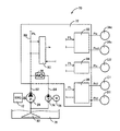
図2は、車両10に備えられた、無段変速機18、クラッチLU、前進用クラッチC1、及び後進用ブレーキB1に関わる作動を制御する油圧システム70の概略構成を説明する図である。図2において、油圧システム70は、油圧制御回路72に加え、機械式オイルポンプ28及び電動式オイルポンプ74を備えている。
FIG. 2 is a diagram illustrating a schematic configuration of a
機械式オイルポンプ28は、エンジン12に機械的に連結されており、そのエンジン12よって回転駆動されることにより、無段変速機18を変速制御したり、無段変速機18におけるベルト挟圧力を発生させたり、前後進切換装置16における動力伝達経路を切り換えたり、クラッチLUの作動状態を切り替えたり、車両10の動力伝達経路の各部に潤滑油を供給したりする為の作動油圧の元圧となる油圧を発生する(吐出する)。電動式オイルポンプ74は、機械式オイルポンプ28とは並列に配置されて、電動モータ76によって回転駆動されることにより、エンジン12の回転状態に拘わらず(例えばエンジン12の回転停止時に)、上記作動油圧の元圧となる油圧を発生する(吐出する)ことができる。機械式オイルポンプ28は、例えば後述するエンジン12の自動停止再始動制御(エコラン制御)においてエンジン12が自動停止させられると、作動油を吐出できない。その為、電動式オイルポンプ74は、例えば車両10の減速走行中乃至停車中に実行されるようなエコラン制御におけるエンジン自動停止時に作動させられる。このように、電動式オイルポンプ74は、専ら、機械式オイルポンプ28の代替として一時的に用いられるので、例えば定格上の最大吐出流量が、機械式オイルポンプの吐出流量よりも少ない吐出流量とされて、小型化が図られている。
The
機械式オイルポンプ28及び電動式オイルポンプ74は、ハウジング32(トランスミッションケース)の下部に設けられたオイルパン78に還流した作動油を、共通の吸い込み口(ストレーナ)80から吸い上げて、各々吐出油路82,84へ吐出する。吐出油路82は直接的に、吐出油路84は油圧制御回路72内に設けられた逆止弁86を介して、各々、油圧制御回路72内の油路(例えばライン圧PLが流通するライン圧油路88)に連結されている。逆止弁86は、吐出油路82と吐出油路84との間に設けられており、機械式オイルポンプ28から出力された油圧が吐出油路84側へ流入することを防止する。
The
油圧制御回路72は、機械式オイルポンプ28及び/又は電動式オイルポンプ74から吐出される油圧を元圧としてライン圧PLを調圧するレギュレータ弁90、ライン圧PLを元圧として無段変速機18の変速作動及びベルト挟圧力を制御するCVT油圧制御系92、ライン圧PLを元圧としてクラッチLUの係合解放作動を制御するLU油圧制御系94、ライン圧PLを元圧として前進用クラッチC1及び後進用ブレーキB1の係合解放作動を制御するC1/B1油圧制御系96などを備えている。
The
CVT油圧制御系92は、例えば油圧アクチュエータ34cへ供給する作動油圧であるプライマリ圧Pinを調圧するコントロール弁やそのコントロール弁を作動させる電磁弁、油圧アクチュエータ38cへ供給する作動油圧であるセカンダリ圧Poutを調圧するコントロール弁やそのコントロール弁を作動させる電磁弁等を備えている。従って、CVT油圧制御系92は、オイルポンプ28,74が吐出する油圧を元圧として、油圧アクチュエータ34c,38cへ作動油圧を供給することができる。
For example, the CVT
LU油圧制御系94は、例えばクラッチLUの作動状態を切り替える為の切替弁、クラッチLUへ供給する作動油圧であるロックアップクラッチ圧(LUクラッチ圧)Pluを調圧するコントロール弁、その切替弁及びコントロール弁を作動させる1つ乃至複数の電磁弁等を備えている。従って、LU油圧制御系94は、オイルポンプ28,74が吐出する油圧を元圧として、クラッチLUへ作動油圧を供給することができる。
The LU
C1/B1油圧制御系96は、例えば前進用クラッチC1へ供給する作動油圧であるC1クラッチ圧Pc1を調圧制御して出力する電磁弁、後進用ブレーキB1へ供給する作動油圧であるB1ブレーキ圧Pb1を調圧制御して出力する電磁弁等を備えている。従って、C1/B1油圧制御系96は、オイルポンプ28,74が吐出する油圧を元圧として、前進用クラッチC1及び後進用ブレーキB1へ作動油圧を供給することができる。
The C1 / B1
図1に戻り、本実施例の電子制御装置50は、イグニッションキーやイグニッションスイッチ等のユーザ操作によるエンジン12の始動/停止とは別に、例えば車両10が交差点等で一時停止した際に、又は低車速にて前進走行(例えば減速走行)している際に、燃費の向上、排気ガスの低減、騒音の低減等の為に、ユーザ操作に因らず、エンジン12を自動的に一時停止し、その後にエンジン12を自動的に再始動するエンジン12の自動停止再始動制御(エコラン制御、アイドリングストップ制御)を実行する。その為、電子制御装置50は、エコラン制御を実行するエコラン制御手段すなわちエコラン制御部64を機能的に備えている。
Returning to FIG. 1, the
エコラン制御部64は、例えば所定のエンジン停止条件(アイドリングストップ開始条件)が成立した場合には、フューエルカット制御等を実行してエンジン12を一時的に停止する。この際、エコラン制御部64は、電動式オイルポンプ74を回転駆動して油圧を出力する為に電動モータ76を駆動し、油圧制御回路72へ油圧を供給する。一方、エコラン制御部64は、所定のエンジン再始動条件が成立した場合には、不図示のスタータによりエンジン12を回転駆動(クランキング)すると共に、そのクランキングに連動して、電子スロットル弁の開閉制御や燃料供給制御や点火時期制御を実行してエンジン12を再始動する。又、エコラン制御部64は、エンジン12の再始動後には(例えばエンジン12が完爆した(自律回転した)と判断できる為の予め定められた所定回転速度以上にエンジン回転速度Neが上昇した後には)、電動式オイルポンプ74の駆動を停止する。これにより、エンジン12の停止時には電動式オイルポンプ74に基づく作動油圧が油圧アクチュエータ34c,38cや前進用クラッチC1へ供給される。
For example, when a predetermined engine stop condition (idling stop start condition) is satisfied, the
上記所定のエンジン停止条件は、例えばシフトポジション(シフトレンジ)が「P」,「N」,「D」ポジション(レンジ)の何れかであり、且つアクセル開度Accが零と判定されるアクセルオフであり、且つ車速Vが零と判定される車両停止中(或いは車速Vが予め定められたエコラン許可車速以下と判定される低速走行中)あるなどの条件である。更に、シフトポジションが「D」ポジションであるときには、ホイールブレーキがオン状態(ブレーキオン)であるという条件が、所定のエンジン停止条件として加えられる。一方で、上記所定のエンジン再始動条件は、例えば上記所定のエンジン停止条件の成立後に、その所定のエンジン停止条件が成立しなくなったことで成立させられる。 The predetermined engine stop condition is, for example, that the shift position (shift range) is any one of “P”, “N”, and “D” positions (range) and the accelerator opening Acc is determined to be zero. The vehicle speed is determined to be zero and the vehicle is stopped (or the vehicle speed V is determined to be equal to or lower than the predetermined eco-run permission vehicle speed). Further, when the shift position is the “D” position, a condition that the wheel brake is on (brake on) is added as a predetermined engine stop condition. On the other hand, the predetermined engine restart condition is satisfied when, for example, the predetermined engine stop condition is not satisfied after the predetermined engine stop condition is satisfied.
ところで、車両10の前進走行中にエコラン制御部64によるエコラン制御を実行しているときに、運転者により車両10を急減速させる急減速操作が行われる可能性がある。このような急減速操作では、駆動輪24から伝動ベルト40までは回転速度が急低下させられ、入力軸30上における回転慣性体(すなわち入力軸30に連結されている状態にある回転慣性体、例えば入力軸30自身、タービン翼車14t、遊星歯車装置16p、プライマリプーリ34など)による大きなイナーシャトルクが無段変速機18へ入力され易くなる。エコラン制御の実行中は、電動式オイルポンプ74による油圧供給に切り替わる為、ベルト挟圧力がエンジン運転中に比べて低くなり、入力されるイナーシャトルクが無段変速機18のトルク容量(ベルト挟圧力)を上回って、ベルト滑りが発生する恐れがある。このことは、より高車速域からエコラン制御を実行し難いということに繋がり、エコラン制御による燃費向上効果が得られ難くなる。
By the way, when the eco-run control by the
そこで、本実施例の電子制御装置50は、車両10の前進走行中におけるエコラン制御の実行中に車両10の急制動が行われた場合(例えば車両10が急制動された場合や駆動輪24の回転速度が急低下した場合等)は、クラッチLU及び後進用ブレーキB1のうちの少なくとも一方を係合する。これは、入力軸30上における回転慣性体によるイナーシャトルクの発生が抑制乃至防止されるように、車両10の急制動に合わせてその回転慣性体の回転を強制的に低下乃至停止させる為、或いは車両10の急制動時にその回転慣性体によるイナーシャトルクをクラッチLU及び/又は後進用ブレーキB1に分担させる為である。例えば、急制動が為された前進走行中に(すなわち前進用クラッチC1の係合によりタービン軸26(タービン翼車14t)が入力軸30に直結された状態で)クラッチLUを係合すれば、回転低下乃至回転停止したエンジン12の慣性によって、急制動に合わせて入力軸30上における回転慣性体の回転を強制的に低下乃至停止させられるか、或いは急制動に伴うその回転慣性体によるイナーシャトルクをクラッチLUに分担させられる。又、急制動が為された前進走行中に(すなわち前進用クラッチC1の係合により遊星歯車装置16pが一体回転させられた状態で)後進用ブレーキB1を係合すれば、非回転部材であるハウジング32に遊星歯車装置16pが連結されることによって、急制動に合わせて入力軸30上における回転慣性体の回転を強制的に停止させられるか、或いは急制動に伴うその回転慣性体によるイナーシャトルクを後進用ブレーキB1に分担させられる。
In view of this, the
又、低μ路走行中の急減速操作では、車輪の制動(回転低下)が急となり易い。従って、低μ路走行中には急減速操作に備えて、事前にクラッチLU及び/又は後進用ブレーキB1に油圧を供給しておいても良い。そこで、本実施例の電子制御装置50は、車両10の急制動が行われた場合のクラッチLU及び/又は後進用ブレーキB1の係合時の応答性を向上させる為に、エコラン制御の実行中に車両10の走行路が低μ路であると判断された場合は、車両10の急制動が行われた場合に係合する、クラッチLU及び/又は後進用ブレーキB1に対してトルク容量が生じない程度の所定油圧を供給する。この所定油圧は、例えばクラッチLUや後進用ブレーキB1毎に、供給油圧を増やせば速やかにトルク容量を発生させられる油圧として予め実験的に或いは設計的に求められて記憶された(すなわち予め定められた)トルク容量発生直前の充填油圧値である。
Further, in a sudden deceleration operation while traveling on a low μ road, the braking (reduction in rotation) of the wheels tends to be sudden. Therefore, the hydraulic pressure may be supplied to the clutch LU and / or the reverse brake B1 in advance in preparation for a sudden deceleration operation while traveling on a low μ road. Therefore, the
より具体的には、電子制御装置50は、更に、走行状態判断手段すなわち走行状態判断部66、及びクラッチ油圧制御手段すなわちクラッチ油圧制御部68を備えている。
More specifically, the
走行状態判断部66は、例えば車両10の走行路が低μ路であるか否かを判定する。例えば、走行状態判断部66は、不図示の車輪速センサにより検出された各車輪の回転速度を用いて、前後輪の回転速度差が所定回転速度差以上であるか否かに基づいて車両10の走行路が低μ路であるか否かを判定する。或いは、走行状態判断部66は、アクセルオン時に駆動輪24の回転速度の変化速度がアクセルオン時所定変化速度以上であるか否かに基づいて車両10の走行路が低μ路であるか否かを判定する。或いは、走行状態判断部66は、ブレーキオン時に何れかの車輪の回転速度の変化速度がブレーキオン時所定変化速度以上であるか否かに基づいて車両10の走行路が低μ路であるか否かを判定する。走行状態判断部66は、例えば車両10の走行路が低μ路であると判定した場合には、低μ路フラグをオフからオンへ切り替える。前記所定回転速度差、前記アクセルオン時所定変化速度、及び前記ブレーキオン時所定変化速度は、各々、例えばそのときのアクセル開度θacc或いはブレーキ操作量Qbraにおいて走行路が低μ路であると判断する為の予め定められた下限の判定閾値である。
For example, the traveling
又、走行状態判断部66は、例えば車両10の前進走行中(すなわちアクセルオフの減速走行中)においてエコラン制御の実行中であるか否かを、エコラン制御部64によるエンジン12のフューエルカット制御等が実行されているか否かに基づいて判定する。走行状態判断部66は、例えば減速走行中のエコラン制御(すなわち減速時エコラン制御)の実行中であると判定した場合には、低μ路フラグがオンであるか否かに基づいて、低μ路走行中であるか否かを判定する。
Further, the traveling
又、走行状態判断部66は、例えば車両10の急制動が行われたか否かを判定(検知)する。例えば、走行状態判断部66は、ブレーキ操作量Qbraが所定操作量以上であり、且つブレーキ操作量Qbraの変化速度が所定操作量変化速度以上であるか否かに基づいて、車両10の急制動が行われたか否かを判定する。前記所定操作量及び前記所定操作量変化速度は、例えば運転者による制動操作が急操作であると判断する為の予め定められた下限の判定閾値である。
The traveling
クラッチ油圧制御部68は、例えば走行状態判断部66により減速時エコラン制御の実行中且つ低μ路走行中と判定された場合には、走行状態判断部66による急制動判定時に係合する、クラッチLU及び/又は後進用ブレーキB1に対して所定油圧を供給する指令を油圧制御回路72へ出力する。又、クラッチ油圧制御部68は、例えば走行状態判断部66により減速時エコラン制御の実行中且つ低μ路走行中且つ車両10が急制動と判定された場合には、上記所定油圧を供給した、クラッチLU及び/又は後進用ブレーキB1を係合する指令を油圧制御回路72へ出力する。
The clutch hydraulic
図3は、電子制御装置50の制御作動の要部すなわち減速時エコラン制御の実行中に車両10の急制動が行われたとしても無段変速機18のベルト滑りを抑制乃至防止する為の制御作動を説明するフローチャートであり、例えば数msec乃至数十msec程度の極めて短いサイクルタイムで繰り返し実行される。
FIG. 3 shows a control part for controlling or preventing belt slippage of the continuously
図3において、先ず、走行状態判断部66に対応するステップ(以下、ステップを省略する)S10において、例えば減速時エコラン制御の実行中であるか否かが判定される。このS10の判断が否定される場合は本ルーチンが終了させられるが肯定される場合は走行状態判断部66に対応するS20において、例えば低μ路走行中であるか否かが判定される。このS20の判断が否定される場合は本ルーチンが終了させられるが肯定される場合はクラッチ油圧制御部68に対応するS30において、例えば後述するS50にて係合する、クラッチLU及び/又は後進用ブレーキB1に対して所定油圧を供給(充填)する指令が油圧制御回路72へ出力される。次いで、走行状態判断部66に対応するS40において、例えば車両10の急制動が行われたか否かが判定される。このS40の判断が否定される場合は本ルーチンが終了させられるが肯定される場合はクラッチ油圧制御部68に対応するS50において、例えば上記S30にて所定油圧が充填された、クラッチLU及び/又は後進用ブレーキB1を係合する指令が油圧制御回路72へ出力される。
In FIG. 3, first, in step (hereinafter, step is omitted) S10 corresponding to the traveling
上述のように、本実施例によれば、車両10の急制動に合わせて無段変速機18の入力側の回転慣性体(すなわち入力軸30上における回転慣性体)の回転を強制的に停止させられるか、或いは車両10の急制動時に無段変速機18の入力側の回転慣性体によるイナーシャトルクをクラッチLU及び/又は後進用ブレーキB1に分担させられる。これにより、無段変速機18へ入力される上記イナーシャトルクを軽減することができる。よって、減速時エコラン制御の実行中に車両10の急制動が行われたとしても、無段変速機18のベルト滑りを抑制乃至防止することができる。又、減速時エコラン制御を実施できる車速Vが高車速領域まで拡大されて、更なる燃費向上に寄与する。尚、クラッチLU及び後進用ブレーキB1を係合する場合は、クラッチLU又は後進用ブレーキB1を係合する場合と比べて、上述した効果が得られ易い。
As described above, according to the present embodiment, the rotation of the rotary inertia body on the input side of the continuously variable transmission 18 (that is, the rotary inertia body on the input shaft 30) is forcibly stopped in accordance with the sudden braking of the
以上、本発明の実施例を図面に基づいて詳細に説明したが、本発明はその他の態様においても適用される。 As mentioned above, although the Example of this invention was described in detail based on drawing, this invention is applied also in another aspect.
例えば、前述の実施例では、エコラン制御部64による減速時エコラン制御時には、前進用クラッチC1は係合したままであったが、燃費向上効果がより得られるように、エンジン12の停止(フューエルカット制御)と併せて、前進用クラッチC1を解放してニュートラル状態としても良い。そして、このようにエコラン制御時においてエンジン12の停止と併せて前進用クラッチC1を解放する場合に、エコラン制御の実行中に車両10の急制動が行われた場合には、クラッチLU及び/又は後進用ブレーキB1を係合することと併せて前進用クラッチC1を係合する。このようにすることで、車両10の急制動に合わせて無段変速機18の入力側の回転慣性体の回転を適切に停止させられるか、或いは車両10の急制動時に無段変速機18の入力側の回転慣性体によるイナーシャトルクをクラッチLU及び/又は後進用ブレーキB1に適切に分担させられる。
For example, in the above-described embodiment, during the eco-run control during deceleration by the
また、前述の実施例では、走行状態判断部66は、ブレーキ操作量Qbraに基づいて車両10の急制動が行われたか否かを判定したが、この判定方法に限らない。例えば、そのときのブレーキ操作量Qbraに対する車輪の回転速度の変化速度が判定閾値を超えているか否かに基づいて車両10の急制動が行われたか否かを判定するなど、種々の判定方法(検知方法)が用いられる。
In the above-described embodiment, the traveling
また、前述の実施例における図3のフローチャートにおいて、S20及びS30が備えられなくても本発明は成立させられるなど、各ステップは差し支えのない範囲で適宜変更することができる。 Further, in the flowchart of FIG. 3 in the above-described embodiment, each step can be appropriately changed within a range that does not interfere with the present invention, for example, the present invention can be established even if S20 and S30 are not provided.
また、前述の実施例において、例えばトルクコンバータ14に替えて、トルク増幅作用のない流体継手(フルードカップリング)などの他の流体式伝動装置が用いられても良い。又、前後進切換装置16の遊星歯車装置16pはダブルピニオン型であったが、シングルピニオン型の遊星歯車装置であっても良い。
In the above-described embodiment, for example, instead of the
尚、上述したのはあくまでも一実施形態であり、本発明は当業者の知識に基づいて種々の変更、改良を加えた態様で実施することができる。 The above description is only an embodiment, and the present invention can be implemented in variously modified and improved forms based on the knowledge of those skilled in the art.
10:車両
12:エンジン
14:トルクコンバータ(流体式伝動装置)
16:前後進切換装置
16p:遊星歯車装置
16s:サンギヤ(回転要素)
16c:キャリア(回転要素)
16r:リングギヤ(回転要素)
18:ベルト式無段変速機
24:駆動輪
32:ハウジング(非回転部材)
50:電子制御装置(制御装置)
LU:ロックアップクラッチ
C1:前進用クラッチ(クラッチ要素)
B1:後進用ブレーキ(ブレーキ要素)
10: Vehicle 12: Engine 14: Torque converter (fluid transmission)
16: Forward /
16c: Carrier (rotating element)
16r: Ring gear (rotating element)
18: Belt type continuously variable transmission 24: Drive wheel 32: Housing (non-rotating member)
50: Electronic control device (control device)
LU: lock-up clutch C1: forward clutch (clutch element)
B1: Reverse brake (brake element)
Claims (1)
前記アイドリングストップ制御の実行中に前記車両の急制動が行われた場合は、前記ロックアップクラッチ及び前記ブレーキ要素のうちの少なくとも一方を係合することを特徴とする車両の制御装置。 An engine, a fluid transmission device having a lock-up clutch, a planetary gear device, a clutch element that selectively rotates the planetary gear device integrally, and a rotating element of the planetary gear device selectively. A brake element connected to a non-rotating member, and a forward power transmission path is established by engaging the clutch element and releasing the brake element, while moving backward by releasing the clutch element and engaging the brake element. A vehicle comprising: a forward / reverse switching device that establishes a power transmission path for a vehicle; and a belt-type continuously variable transmission that forms part of a power transmission path between the forward / backward switching device and a drive wheel. A vehicle control device capable of executing idling stop control for stopping the engine during forward traveling,
When the vehicle is suddenly braked during the idling stop control, at least one of the lockup clutch and the brake element is engaged.
Priority Applications (1)
| Application Number | Priority Date | Filing Date | Title |
|---|---|---|---|
| JP2013244042A JP2015102190A (en) | 2013-11-26 | 2013-11-26 | Vehicle control device |
Applications Claiming Priority (1)
| Application Number | Priority Date | Filing Date | Title |
|---|---|---|---|
| JP2013244042A JP2015102190A (en) | 2013-11-26 | 2013-11-26 | Vehicle control device |
Publications (1)
| Publication Number | Publication Date |
|---|---|
| JP2015102190A true JP2015102190A (en) | 2015-06-04 |
Family
ID=53378051
Family Applications (1)
| Application Number | Title | Priority Date | Filing Date |
|---|---|---|---|
| JP2013244042A Pending JP2015102190A (en) | 2013-11-26 | 2013-11-26 | Vehicle control device |
Country Status (1)
| Country | Link |
|---|---|
| JP (1) | JP2015102190A (en) |
Cited By (2)
| Publication number | Priority date | Publication date | Assignee | Title |
|---|---|---|---|---|
| JP2017044307A (en) * | 2015-08-28 | 2017-03-02 | ダイハツ工業株式会社 | Control device for vehicle |
| JP2017137949A (en) * | 2016-02-04 | 2017-08-10 | アイシン・エィ・ダブリュ株式会社 | Transmission |
Citations (2)
| Publication number | Priority date | Publication date | Assignee | Title |
|---|---|---|---|---|
| JP2005121140A (en) * | 2003-10-16 | 2005-05-12 | Honda Motor Co Ltd | Hydraulic controller of power transmission device |
| WO2013057781A1 (en) * | 2011-10-17 | 2013-04-25 | トヨタ自動車株式会社 | Vehicle control device |
-
2013
- 2013-11-26 JP JP2013244042A patent/JP2015102190A/en active Pending
Patent Citations (2)
| Publication number | Priority date | Publication date | Assignee | Title |
|---|---|---|---|---|
| JP2005121140A (en) * | 2003-10-16 | 2005-05-12 | Honda Motor Co Ltd | Hydraulic controller of power transmission device |
| WO2013057781A1 (en) * | 2011-10-17 | 2013-04-25 | トヨタ自動車株式会社 | Vehicle control device |
Cited By (4)
| Publication number | Priority date | Publication date | Assignee | Title |
|---|---|---|---|---|
| JP2017044307A (en) * | 2015-08-28 | 2017-03-02 | ダイハツ工業株式会社 | Control device for vehicle |
| JP2017137949A (en) * | 2016-02-04 | 2017-08-10 | アイシン・エィ・ダブリュ株式会社 | Transmission |
| WO2017134965A1 (en) * | 2016-02-04 | 2017-08-10 | アイシン・エィ・ダブリュ株式会社 | Speed shift device |
| CN108474469A (en) * | 2016-02-04 | 2018-08-31 | 爱信艾达株式会社 | Speed change gear |
Similar Documents
| Publication | Publication Date | Title |
|---|---|---|
| JP6256378B2 (en) | Control device for automatic transmission for vehicle | |
| US10001179B2 (en) | Control apparatus for power transmission system | |
| WO2014136280A1 (en) | Vehicle hydraulic control device | |
| JP2010078090A (en) | Vehicle controller | |
| JP5862803B2 (en) | Transmission control apparatus and control method | |
| JP2014052034A (en) | Hydraulic control device for automatic transmission | |
| JP6708307B2 (en) | Power transmission device and control method thereof | |
| JP2015102190A (en) | Vehicle control device | |
| JP6139302B2 (en) | Control device for vehicle lock-up clutch | |
| JP6485311B2 (en) | Vehicle eco-run control device | |
| JP6441565B2 (en) | Continuously variable transmission for vehicle | |
| JP6663511B2 (en) | Vehicle oil pump control device and control method | |
| JP5515974B2 (en) | Hydraulic control device | |
| JP2019203527A (en) | Vehicle control device | |
| JP2011106505A (en) | Control device for vehicular continuously variable transmission | |
| JP2005350017A (en) | Vehicle controller | |
| JP6149335B2 (en) | Vehicle control device | |
| JP2017003007A (en) | Control device of vehicle | |
| JP5515973B2 (en) | Power transmission device | |
| JP6654862B2 (en) | Vehicle control device and vehicle control method | |
| JP2017187064A (en) | Control apparatus for power transmission device | |
| JP6666693B2 (en) | Vehicle control device and vehicle control method | |
| JP5790185B2 (en) | Hydraulic control device for vehicle | |
| JP5387419B2 (en) | Control device for continuously variable transmission for vehicle | |
| JP2014163349A (en) | Control device of internal combustion engine |
Legal Events
| Date | Code | Title | Description |
|---|---|---|---|
| A621 | Written request for application examination |
Free format text: JAPANESE INTERMEDIATE CODE: A621 Effective date: 20160126 |
|
| A131 | Notification of reasons for refusal |
Free format text: JAPANESE INTERMEDIATE CODE: A131 Effective date: 20161213 |
|
| A02 | Decision of refusal |
Free format text: JAPANESE INTERMEDIATE CODE: A02 Effective date: 20170613 |