JP2015102124A - Conduit connection device and conduit connection method - Google Patents
Conduit connection device and conduit connection method Download PDFInfo
- Publication number
- JP2015102124A JP2015102124A JP2013241794A JP2013241794A JP2015102124A JP 2015102124 A JP2015102124 A JP 2015102124A JP 2013241794 A JP2013241794 A JP 2013241794A JP 2013241794 A JP2013241794 A JP 2013241794A JP 2015102124 A JP2015102124 A JP 2015102124A
- Authority
- JP
- Japan
- Prior art keywords
- tube
- pipe
- flexible
- connection
- conduit
- Prior art date
- Legal status (The legal status is an assumption and is not a legal conclusion. Google has not performed a legal analysis and makes no representation as to the accuracy of the status listed.)
- Pending
Links
Images


Abstract
Description
本発明は、位置の異なる第1の導管と第2の導管とを接続する導管接続装置及び導管接続方法に関する。 The present invention relates to a conduit connecting apparatus and a conduit connecting method for connecting a first conduit and a second conduit that are located at different positions.
近年、種々の配管、例えば水道配管において、地震対策、地盤沈下対策として、伸縮可撓管が使用されている。しかし、古い施設では、伸縮可撓管は使用されておらず、多くの施設において地盤沈下による配管の撓みから漏水が発生している。同様に、伸縮可撓管が使用されている施設においても伸縮可撓管の定格性能を超える地盤沈下が発生して漏水に至る例が増えてきている。このため、現在配管が撓んだり、定格性能を超える地盤沈下を吸収した伸縮可撓管を、配管の耐震性能を高める観点から新しい伸縮可撓管に取り替える工事が増えてきている。本件特許出願人は、耐震化に使用可能な伸縮可撓管として、例えば下記のような特許出願を行っている。 In recent years, in various pipes, for example, water pipes, telescopic flexible pipes have been used as countermeasures against earthquakes and ground subsidence. However, in the old facilities, the expansion / contraction flexible tube is not used, and in many facilities, water leakage occurs due to the bending of the piping due to the ground subsidence. Similarly, even in facilities where telescopic flexible tubes are used, there are increasing examples of ground subsidence exceeding the rated performance of telescopic flexible tubes and leading to water leakage. For this reason, the work which replaces the expansion-contraction flexible pipe which absorbed the ground subsidence exceeding the rated performance now with a new expansion-contraction flexible pipe from the viewpoint of improving the seismic performance of piping is increasing. The present patent applicant has filed the following patent application, for example, as an elastic flexible tube that can be used for earthquake resistance.
従来の伸縮可撓管は、直線配管を前提にしたものとなっている。したがって、既に湾曲した配管に対して伸縮可撓管を使用する場合には、本来の変位吸収量を消費して、すなわち伸縮可撓管を湾曲させて位置の異なる既設の水道管の端部間を接続するようにしている。例えば、地盤が100mmの不等沈下を起こしている場合には、例えば性能限界が200mmの伸縮可撓管を使用して、既に地盤沈下している100mm分変位させて使用している。したがって、使用された伸縮可撓管の残存する変位可能能力は、残り100mmになってしまう。したがって、本来であれば、性能限界が変位量100mmの伸縮可撓管を使用すれば良いところ、ここでは、性能限界が変位量200mmの伸縮可撓管を使用しなければならない。大きな変位を吸収することができる伸縮可撓管は、製品全長も長く、既存の配管長、或いは既存の伸縮可撓管の長さを超えるために、その部分だけの取り替えではなく、その前後の配管も動かさなければならなくなる。このため、工事が大がかりとなり、工事日数も増えて、工事費用も嵩んでしまう。従来の伸縮可撓管の使用では、以上のような問題点があった。 Conventional telescopic flexible tubes are premised on straight piping. Therefore, when using an expansion / contraction flexible pipe with respect to an already curved pipe, the original displacement absorption amount is consumed, that is, between the ends of existing water pipes having different positions by bending the expansion / contraction flexible pipe. To connect. For example, when the ground has caused unequal subsidence of 100 mm, for example, an expansion / contraction flexible tube having a performance limit of 200 mm is used and is displaced by 100 mm already subsidized. Therefore, the remaining displaceable ability of the used telescopic flexible tube becomes the remaining 100 mm. Therefore, originally, an elastic flexible tube having a performance limit of 100 mm may be used, but here, an elastic flexible tube having a performance limit of 200 mm must be used. The expansion / contraction flexible tube that can absorb a large displacement has a long product overall length and exceeds the existing piping length or the length of the existing expansion / contraction flexible tube. The piping will also have to be moved. For this reason, construction becomes large, construction days increase, and construction costs increase. The use of the conventional telescopic flexible tube has the above problems.
本発明は、このような従来の事情に鑑みて提案されたものであり、可撓管が本来有する変位吸収量の全てを新たな地盤沈下や地震対策に使用することができ、更に、工事費用を大幅に削減することができる導管接続装置及び導管接続方法を提供することを目的とする。 The present invention has been proposed in view of such conventional circumstances, and all of the displacement absorption inherent in the flexible tube can be used for new ground subsidence and earthquake countermeasures. It is an object of the present invention to provide a conduit connecting device and a conduit connecting method capable of greatly reducing the above.
上述した目的を達成するために、本発明に係る導管接続装置は、第1の可撓管及び第2の可撓管と、上記第1の可撓管と上記第2の可撓管とを接続する接続管とを備え、上記第1の可撓管、上記第2の可撓管の少なくとも一方は、一端部に凸状球面部を有するスリーブ管と、該凸状球面部を摺動可能に支持する凹状球面部を有する外装管とを有し、上記第1の可撓管の管軸と上記第2の可撓管の管軸とはズレがあり、上記接続管は、当該接続管の管軸が上記第1及び第2の可撓管の管軸に対して傾斜した状態で、上記第1の可撓管と上記第2の可撓管とを接続する。 In order to achieve the above-described object, a conduit connection device according to the present invention includes a first flexible tube, a second flexible tube, the first flexible tube, and the second flexible tube. A connecting tube to be connected, and at least one of the first flexible tube and the second flexible tube is slidable on a sleeve tube having a convex spherical portion at one end, and the convex spherical portion And a tube axis of the first flexible tube is misaligned with a tube axis of the second flexible tube, and the connection tube is connected to the connection tube. The first flexible tube and the second flexible tube are connected in a state where the tube shaft is inclined with respect to the tube axes of the first and second flexible tubes.
更に、上記第1の可撓管のスリーブ管、上記第2の可撓管のスリーブ管のそれぞれの端部には、端管が設けられ、接続される上記端管の端部、上記接続管の端部の両方は、対応する斜めの端面を有し、上記端管の斜めの端面と上記接続管の斜めの端面とが接続されるようにしても良い。 Furthermore, an end tube is provided at each end of the sleeve tube of the first flexible tube and the sleeve tube of the second flexible tube, and the end portion of the end tube to be connected, the connection tube Both of the end portions may have corresponding oblique end surfaces, and the oblique end surface of the end tube may be connected to the oblique end surface of the connection tube.
更に、上記第1の可撓管のスリーブ管、上記第2の可撓管のスリーブ管のそれぞれの端部には、上記接続管と接続される端管が設けられ、上記端管又は上記接続管は、滑らかな曲線状に設けられているようにしても良い。 Furthermore, an end tube connected to the connection tube is provided at each end of the sleeve tube of the first flexible tube and the sleeve tube of the second flexible tube, and the end tube or the connection The tube may be provided in a smooth curved shape.
更に、上記第1の可撓管は、第1の位置にある第1の導管と接続され、上記第2の可撓管は、上記第1の位置からズレた第2の位置にある第2の導管と接続されるようにしても良い。 Furthermore, the first flexible tube is connected to a first conduit in a first position, and the second flexible tube is in a second position that is shifted from the first position. You may make it connect with the conduit | pipe.
更に、上記接続管は、管軸方向に伸縮可能に設けられているようにしても良い。 Furthermore, the connecting pipe may be provided so as to be extendable and contractible in the pipe axis direction.
更に、上記接続管は、上記第1の可撓管と上記第2の可撓管とのうちの一方と接続される第1の接続管と、他方と接続される第2の接続管とを有し、該第1の接続管に該第2の接続管が挿入され、該第1の接続管に対して該第2の接続管が管軸方向に摺動可能に設けられているようにしても良い。 Furthermore, the connection pipe includes a first connection pipe connected to one of the first flexible pipe and the second flexible pipe, and a second connection pipe connected to the other. And the second connecting pipe is inserted into the first connecting pipe, and the second connecting pipe is slidable in the pipe axis direction with respect to the first connecting pipe. May be.
更に、上記第1の可撓管と上記第2の可撓管の少なくとも一方は、可撓性及び伸縮性を有する伸縮可撓管であるようにしても良い。 Further, at least one of the first flexible tube and the second flexible tube may be a telescopic flexible tube having flexibility and stretchability.
また、本発明に係る導管接続方法は、第1の位置にある第1の導管と上記第1の位置からズレた第2の位置にある第2の導管とを接続する導管接続方法において、第1の可撓管及び第2の可撓管と、上記第1の可撓管と上記第2の可撓管とを接続する接続管とを備え、上記第1の可撓管、上記第2の可撓管の少なくとも一方は、一端部に凸状球面部を有するスリーブ管と、該凸状球面部を摺動可能に支持する凹状球面部を有する外装管とを有し、上記第1の可撓管の管軸と上記第2の可撓管の管軸とはズレがあり、上記接続管は、当該接続管の管軸が上記第1及び第2の可撓管の管軸に対して傾斜した状態で、上記第1の可撓管と上記第2の可撓管とを接続している導管接続装置を、上記第1の導管と上記第2の導管との間に配置し、上記第1の可撓管を上記第1の導管に接続し、上記第2の可撓管を上記第2の導管に接続する。 The conduit connection method according to the present invention is the conduit connection method for connecting the first conduit in the first position and the second conduit in the second position shifted from the first position. A first flexible tube, a second flexible tube, and a connection tube connecting the first flexible tube and the second flexible tube, the first flexible tube and the second flexible tube. At least one of the flexible tubes has a sleeve tube having a convex spherical portion at one end, and an outer tube having a concave spherical portion that slidably supports the convex spherical portion, and the first tube The tube axis of the flexible tube is misaligned with the tube axis of the second flexible tube, and the connection tube has a tube axis of the connection tube with respect to the tube axes of the first and second flexible tubes. A conduit connection device that connects the first flexible tube and the second flexible tube in a tilted state between the first conduit and the second conduit; Above Connect the flexible tube to the first conduit, connecting the second flexible tube into the second conduit.
また、本発明に係る導管接続装置は、一の可撓管と、上記一の可撓管と他の可撓管とを接続する接続管とを備え、上記一の可撓管は、一端部に凸状球面部を有するスリーブ管と、該凸状球面部を摺動可能に支持する凹状球面部を有する外装管とを有し、上記接続管は、当該接続管の管軸が上記一の可撓管の管軸に対して傾斜した状態で上記一の可撓管と接続されており、上記接続管の他端は、上記他の可撓管と接続される。 The conduit connection device according to the present invention includes one flexible tube and a connection tube that connects the one flexible tube and another flexible tube, and the one flexible tube has one end portion. A sleeve tube having a convex spherical portion and an outer tube having a concave spherical portion that slidably supports the convex spherical portion, and the connecting tube has a tube axis of the connecting tube The flexible tube is connected to the one flexible tube while being inclined with respect to the tube axis of the flexible tube, and the other end of the connection tube is connected to the other flexible tube.
更に、上記一の可撓管のスリーブ管には、端管が設けられ、上記端管の斜めの端面と上記接続管の斜めの端面とが接続されるようにしても良い。 Furthermore, the sleeve tube of the one flexible tube may be provided with an end tube, and the oblique end surface of the end tube may be connected to the oblique end surface of the connection tube.
更に、上記一の可撓管のスリーブ管には、端管が設けられ、上記端管又は上記接続管は、滑らかな曲線状に設けられているようにしても良い。 Furthermore, the sleeve tube of the one flexible tube may be provided with an end tube, and the end tube or the connection tube may be provided in a smooth curved shape.
更に、上記一の可撓管は、第1の位置にある第1の導管と接続され、上記接続管の他端は、上記第1の位置からズレた第2の位置にある第2の導管と接続された上記他の可撓管と接続されるようにしても良い。 The one flexible tube is connected to a first conduit in a first position, and the other end of the connection tube is a second conduit in a second position shifted from the first position. You may make it connect with the said other flexible tube connected.
更に、上記接続管は、管軸方向に伸縮可能に設けられているようにしても良い。 Furthermore, the connecting pipe may be provided so as to be extendable and contractible in the pipe axis direction.
更に、上記接続管は、上記一の可撓管と上記他の可撓管とのうちの一方と接続される第1の接続管と、他方と接続される第2の接続管とを有し、該第1の接続管に該第2の接続管が挿入され、該第1の接続管に対して該第2の接続管が管軸方向に摺動可能に設けられているようにしても良い。 Further, the connection pipe has a first connection pipe connected to one of the one flexible pipe and the other flexible pipe, and a second connection pipe connected to the other. The second connection pipe may be inserted into the first connection pipe, and the second connection pipe may be slidable in the tube axis direction with respect to the first connection pipe. good.
本発明によれば、第1の可撓管と第2の可撓管とを斜めの接続管を介して接続することによって、予め可撓管を変位させる必要がなくなる。したがって、可撓管が本来有する変位吸収量の全てを新たな地盤沈下や地震対策に使用することができる。加えて、導管接続装置の製品長を短くすることができる。 According to the present invention, it is not necessary to displace the flexible tube in advance by connecting the first flexible tube and the second flexible tube via the oblique connection tube. Therefore, all of the amount of displacement that the flexible tube originally has can be used for new ground subsidence and earthquake countermeasures. In addition, the product length of the conduit connection device can be shortened.
以下、本発明を適用した導管接続装置について、図面を参照して説明する。 Hereinafter, a conduit connection device to which the present invention is applied will be described with reference to the drawings.
<導管接続装置の概説>
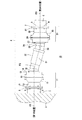
図1に示すように、本発明を適用した導管接続装置10は、地盤沈下等によって高低差や水平方向のズレが発生した第1の導管1と第2の導管2との間を接続する。例えば、第1の導管1は、上水道の管路の途中に設けられるポンプ場や橋梁等の構造物の基礎3に設けられている。このような既設の構造物の基礎3は、一般に強固に設けられ、地盤沈下が少なく、第1の位置にある。これに対して、第2の導管2は、道路等4に埋設され、地盤沈下により沈降する。すなわち、不等沈下が発生して第1の位置よりズレた第2の位置となっており、第1の導管1と第2の導管2との間に高低差や水平方向のズレが発生している。導管接続装置10は、第1の導管1の端部と第2の導管2の端部との間の導管に代えて配設される。
<Outline of conduit connection device>
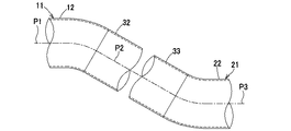
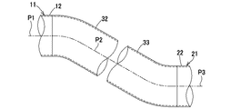
As shown in FIG. 1, a
なお、ここでの導管1,2は、水道管であり、鋼管、鋳鉄管等の金属管、塩化ビニール製の合成樹脂管等が用いられている。
The
<導管接続装置の構成の説明>
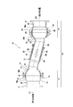
この導管接続装置10は、図1及び図2に示すように、可動部となる第1の可撓管11及び第2の可撓管21と、第1の可撓管11と第2の可撓管21とを接続する接続管31とを備えている。
<Description of configuration of conduit connection device>
As shown in FIGS. 1 and 2, the
<第1の可撓管の説明>
図1及び図2に示すように、第1の可撓管11は、例えばダクタイル鋳鉄製であり、端管12の一端部に第1の凸状球面部13を有する第1のスリーブ管14と、第1の凸状球面部13を受ける第1の凹状球面部15を有する第1の外装管16とで構成されている。
<Description of the first flexible tube>
As shown in FIGS. 1 and 2, the first
第1の外装管16は、前方部材16aと後方部材16bとの二部材で構成されている。前方部材16aには、一端側に形成されたフランジ部17を介して第1の導管1が接合される。更に、第1の外装管16は、前方部材16aと後方部材16bとを組み合わせて第1の凹状球面部15の内部に第1の凸状球面部13を収納した状態で、前方部材16aと後方部材16bとをボルト及びナット等の締結部材18や溶接等の周知の接続方法によって接続して、第1の凹状球面部15でボール状の第1の凸状球面部13を半分以上覆うことで、第1のスリーブ管14の脱落を防止している。更に、第1の凸状球面部13と第1の凹状球面部15との間は、ゴムパッキン19によってシールされている。
The first
したがって、第1の可撓管11は、第1の凸状球面部13が第1の凹状球面部15に対して摺動することで回転屈曲することができる。
Therefore, the first
<第2の可撓管の説明>
図1及び図2に示すように、第2の可撓管21は、例えばダクタイル鋳鉄製であり、端管22の他端部に第2の凸状球面部23を有する第2のスリーブ管24と、第2の凸状球面部23を受ける第2の凹状球面部25を有する第2の外装管26とで構成されている。
<Description of the second flexible tube>
As shown in FIGS. 1 and 2, the second
第2の外装管26は、前方部材26aと後方部材26bとの二部材で構成されている。前方部材26aには、他端側に形成されたフランジ部27を介して第2の導管2が接合される。更に、第2の外装管26は、前方部材26aと後方部材26bとを組み合わせて第2の凹状球面部25の内部に第2の凸状球面部23を収納した状態で、前方部材26aと後方部材26bとをボルト及びナット等の締結部材28や溶接等の周知の接続方法によって接続して、第2の凹状球面部25でボール状の第2の凸状球面部23を半分以上覆うことで、第2のスリーブ管24の脱落を防止している。更に、第2の凸状球面部23と第2の凹状球面部25との間は、ゴムパッキン29によってシールされている。
The second
したがって、第2の可撓管21は、第2の凸状球面部23が第2の凹状球面部25に対して摺動することで回転屈曲することができる。
Therefore, the second
<接続管の説明>
第1の可撓管11と第2の可撓管21との間には、図1及び図2に示すように、接続管31が配設される。接続管31は、第1の可撓管11の端管12と第2の可撓管21の端管22との間に接続されるものであり、端管12,22の内径とほぼ等しい内径を有する直管である。
<Description of connecting pipe>
Between the first
更に、接続管31は、例えば、第1の可撓管11の端管12と接続される第1の接続管32と、第2の可撓管21の端管22と接続される第2の接続管33とを有する。第1の接続管32が太径で、第2の接続管33が小径で、第1の接続管32に第2の接続管33が挿入可能に構成されている。更に、大径の第1の接続管32の内周面には、第1の係合突起34が形成され、小径の第2の接続管33の外周面には、第2の係合突起35が形成されている。小径の第2の接続管33は、外周面に形成された第2の係合突起35と大径の第1の接続管32の内周面に形成された第1の係合突起34とが係合することで、大径の第1の接続管32の内部に必要以上に入り込まないように構成されている。更に、第1の接続管32と第2の接続管33との間は、ゴムパッキン36によってシールされている。
Further, the
したがって、導管接続装置10は、第1の接続管32に対して第2の接続管33が直線的に摺動することで伸縮することができる。すなわち、導管接続装置10は、第1及び第2の凸状球面部13,23が第1及び第2の凹状球面部15,25に対して摺動することで回転屈曲することができることに加え、第1の接続管32に対して第2の接続管33が直線的に摺動することで伸縮することができる。
Therefore, the
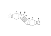
更に、上述した第1の可撓管11と第2の可撓管21は、共に、図1及び図2に示すように、第1の可撓管11の第1の凸状球面部13と第1の凹状球面部15との部分が湾曲されず、第2の可撓管21の第2の凸状球面部23と第2の凹状球面部25との部分が湾曲されず、管軸P1,P3が真っ直ぐで略水平の状態とされている。接続管31は、第1の可撓管11と第2の可撓管21との間に発生する高低差といった鉛直方向のズレや水平方向のズレを埋める。このため、接続管31は、第1の可撓管11と第2の可撓管21との間に、それぞれの可撓管11,21の管軸P1,P3に対して斜めに配設される。
Furthermore, both the first
そこで、第1の可撓管11の端管12の端部と第1の接続管32の端管12側の端部は、図3に示すように、第1の接続管32の傾斜に合わせて、斜めに加工される。具体的に、端管12の端部の直径と第1の接続管32の端管12側の端部との直径は同じである。そして、端管12は、管軸P1に対して角度a1だけ斜めに加工され、第1の接続管32の端部は、管軸P2に対して角度b1だけ斜めに加工される(a1=b1)。すなわち、端管12の端部と第1の接続管32の端部の開口端(端面)は、楕円状となるように形成される。そして、端管12の端部と第1の接続管32の端部とは、溶接等によって接合される。これにより、第1の可撓管11と第1の接続管32とは、第1の可撓管11の管軸に対して斜めになるように接続される。
Therefore, the end portion of the
また、第2の可撓管21の端管22の端部と第2の接続管33の端管22側の端部も、第2の接続管33の傾斜に合わせて、斜めに加工される。具体的に、端管22の端部の直径と第2の接続管33の端管22側の端部との直径は同じである。そして、端管22は、管軸P3に対して角度a2だけ斜めに加工され、第2の接続管33の端部は、管軸P2に対して角度b2だけ斜めに加工される(a2=b2)。すなわち、端管22の端部と第2の接続管33の端部の開口端(端面)は、楕円状となるように形成される。そして、端管22の端部と第2の接続管33の端部とは、溶接等によって接合される。これにより、第2の可撓管21と第2の接続管33とは、第2の可撓管21の管軸に対して斜めになるように接続される。
The end portion of the
なお、接続管31は、第1の接続管32が第1の可撓管11の端管12と接続され、第2の接続管33が第2の可撓管21の端管22と接続されることに限定されるものではなく、第2の接続管33が第1の可撓管11の端管12と接続され、第1の接続管32が第2の可撓管21の端管22と接続されるようにしても良い。
The
<導管接続方法の説明>
以上のように構成された導管接続装置10は、第1の可撓管11の端管12と第2の可撓管21の端管22に接続管31を接続した状態でユニット化されて、工事現場へと運搬される。例えば、接続管31の第1の可撓管11や第2の可撓管21に対する傾斜角や長さは、個々の工事現場の第1の導管1と第2の導管2の位置関係によって決められ、導管接続装置10は、この位置関係に従って製造される。なお、導管接続装置10は、接続管31の第1の可撓管11や第2の可撓管21に対する傾斜角や長さが個々の工事現場の第1の導管1と第2の導管2の位置関係に従って製造される他に、個々の工事現場に従って製造されるのではなく、45°や30°等、予め所定の傾斜角や長さで規格化して製造されるようにしても良い。このような導管接続装置10は、第1の可撓管11と第2の可撓管21とを湾曲させないように、出荷用金具(不図示)等で固定される。
<Description of conduit connection method>
The
工事現場では、敷設溝が切削され、第1の導管1の端部と第2の導管2の端部とを接続している旧導管が露出される。旧導管が第1及び第2の導管1,2から取り外されると、導管接続装置10が代わりに配設される。すなわち、図1に示すように、第1の導管1は、例えば第1の導管1のフランジ部5が第1の可撓管11のフランジ部17とボルト及びナット等の締結部材6や溶接等の周知の接続方法によって接続され、第2の導管2は、例えば第2の導管2のフランジ部7が第2の可撓管21のフランジ部27とボルト及びナット等の締結部材8や溶接等の周知の接続方法によって接続される。この後、導管接続装置10からは、出荷用金具の締結部材が取り外され、第1及び第2の可撓管11,21が湾曲及び伸縮可能な状態にされる。導管接続装置10が第1及び2の導管1,2の間に接続されると、敷設溝は埋め戻しされる。
At the construction site, the laying groove is cut to expose the old conduit connecting the end of the
以上のように構成された導管接続装置10では、第1の導管1と第2の導管2との距離に合わせて接続管31が設けられているので、第1及び第2の可撓管11,21を湾曲(可撓変位)させない状態で、第1の導管1と第2の導管2との間に設置することができる。したがって、第1及び第2の可撓管11,21が本来有する変位吸収量を従前のように損なうことなく、本来有する変位吸収量の全てを新たな地盤沈下や地震対策に使用することができる。更に、導管接続装置10は、接続管31を傾斜させているので、従前より製品長を短くすることができ、全体の構成の軽量化や小型化等を図ることができる。したがって、新規工事の場合だけでなく、配管の交換作業等が行われる狭い場所での利便性を向上させることができる。したがって、配管全体において、耐震化できる箇所が多くなり、配管全体や施設全体の安全性を向上させることができる。
In the
<変形例の説明>
なお、導管接続装置10は、接続管31が第1の接続管32と第2の接続管33とを有し、第1の接続管32に第2の接続管33が挿入され、第1の接続管32に対して第2の接続管33が管軸方向に摺動可能に設けられることで、接続管31が軸線方向に伸縮可能に設けられることに限定されるものではなく、図4に示すように、接続管31の中途部に、可撓性、伸縮性、更には密閉性を有するベローズ管等の伸縮可撓管41を設けることで、接続管31が軸線方向に伸縮可能に設けられるようにしても良い。このような例であっても、接続管31が第1の接続管32と第2の接続管33とで構成された場合と同様に、接続管31が伸縮することができる。更に、このような例であれば、接続管31も湾曲(可撓変位)して変位吸収することができるので、より大きな地盤沈下や地震に対して耐え得ることができる。なお、伸縮可撓管41は、従来公知のベローズ管等、可撓性、伸縮性、更には密閉性を有する管であれば、従来公知の如何なる管であっても良い。
<Description of modification>
In the
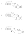
また、導管接続装置10は、図5及び図6に示すように、第1の可撓管11又は第2の可撓管21の何れか一方を、可撓性、伸縮性、更には密閉性を有するベローズ管等の伸縮可撓管41とするようにしても良い。例えば、伸縮可撓管41としては、可撓性や伸縮性、更には密閉性を有するベローズ管42と、ベローズ管42の一端部に一体に接合される端管43と、ベローズ管42の他端部に一体に接合される端管44とを備える。なお、図5及び図6では、何れも第1の可撓管11を伸縮可撓管41としているが、上述したようにこれに限定されるものではなく、第2の可撓管21を伸縮可撓管41とするようにしても良い。更に、伸縮可撓管41は、従来公知のベローズ管等、可撓性、伸縮性、更には密閉性を有する管であれば、従来公知の如何なる管であっても良い。
In addition, as shown in FIGS. 5 and 6, the
更に、第1の可撓管11又は第2の可撓管21の何れか一方が伸縮可撓管41とされる場合であっても、接続管31が、第1の接続管32に対して第2の接続管33が摺動可能に設けられることによって、又は、中途部に伸縮可撓管41が設けられることによって、伸縮性を有するようにしても良い。
Furthermore, even if either the first
また、第1の可撓管11又は第2の可撓管21の何れか一方が伸縮可撓管41とされる場合においては、伸縮可撓管41が伸縮性を有しているので、伸縮不可の接続管31を用いるようにしても良い。
When either the first
例えば、導管接続装置10は、図5(A)に示すように、接続管31が直管で設けられるようにしても良い。
For example, as shown in FIG. 5A, the
更に、接続管31は、図5(B)に示すように、伸縮可撓管41の端管44又は第2の可撓管21の端管22(第1の可撓管11の端管12)と一体であっても良い。このような場合は、例えば、90°、45°、22.5°、11.25°といったベント管51を用いれば良い。このように、接続管31と端管44又は端管22(端管12)の代わりにベント管51を用いたときには、接続管31と端管44又は端管22(端管12)との溶接作業が不要となり、製造工程の簡素化を実現することができる。なお、ベント管51は、接続管31と端管44及び端管22(端管12)とを一体にしたものであっても良い。
Further, as shown in FIG. 5B, the connecting
更に、図5(C)に示すように、伸縮可撓管41の端管44と第2の可撓管21の端管22(第1の可撓管11の端管12)にベント管52a,52bを使用して、傾斜部分で、フランジ接続するようにしても良い。勿論、ベント管52a,52bとの接続は溶接等の周知の接続方法によって行っても良い。この場合、伸縮可撓管41とベント管52aの部分、第2の可撓管21(第1の可撓管11)とベント管52bの部分、又はこれらを合体した状態を一のユニットとして取り扱うことができる。
Further, as shown in FIG. 5C, the
更に、図5(D)に示すように、接続管にS型のベント管53を使用しても良い。この場合、伸縮可撓管41とベント管53の部分、第2の可撓管21(第1の可撓管11)と端管22(端管12)の部分、又はこれらを合体した状態を一のユニットとして取り扱うことができる。なお、図5(D)では、伸縮可撓管41の端管44と接続管31とを一体にしたS型ベント管53を使用したが、第2の可撓管21の端管22(第1の可撓管11の端管12)と接続管31とを一体にしたS型ベント管53を使用しても良い。なお、他方の可撓管との接続は、フランジ接続であっても良いし、溶接等の周知の接続方法であっても良い。
Further, as shown in FIG. 5D, an S-shaped
更に、図5(E)に示すように、伸縮可撓管41の端管44と第2の可撓管21の端管22(第1の可撓管11の端管12)にベント管52a,52bを用い、傾斜した接続管となる部分(直管部分)で溶接により、2つのベント管を接合するようにしても良い。溶接線は、接続管となる部分(直管部分)の軸線に対して直角であっても良いし、軸線に対して斜めであっても良い。図5(E)では、溶接線が接続管となる部分(直管部分)の軸線に対して直角の例を示している。
Further, as shown in FIG. 5E, the
更に、図6(A)に示すように、導管接続装置10は、異径の第1の導管1と第2の導管2とを接続する際にも用いることができる。この場合、接続管31には、異径管54を用い、一端を、伸縮可撓管41と接続し、他端を、第2の可撓管21(第1の可撓管11)と接続する。なお、伸縮可撓管41と異径管である接続管31の一端との接続及び第2の可撓管21(第1の可撓管11)と接続管31の他端との接続は、フランジ接続であっても良いし、溶接等の周知の接続方法であっても良い。
Furthermore, as shown in FIG. 6 (A), the
また、第1の導管1と第2の導管2とのズレ量が大きい場合には、図5(C)及び図5(E)の場合のように、直接ベント管同士を接続できないこともある。このような場合、図6(B)に示すように、伸縮可撓管41の端管44と第2の可撓管21の端管22(第1の可撓管11の端管12)にベント管52a,52bを用い、ベント管52a,52bの間に直管55を介在させ、接続管となる傾斜した部分を長くすることもできる。なお、ベント管52a,52bと直管55との接続は、フランジ接続であっても良いし、溶接等の周知の接続方法であっても良い。
In addition, when the amount of displacement between the
更に、図6(C)に示すように、伸縮可撓管41の端管44と接続管31とを一体にすると共に、第2の可撓管21の端管22(第1の可撓管11の端管12)と接続管31とを一体にしたS型ベント管56を用いている。これによって、伸縮可撓管41とベント管56と第2の可撓管21(第1の可撓管11)との部分を合体した状態を一のユニットとして取り扱うことができる。
Further, as shown in FIG. 6C, the
また、導管接続装置10は、図3に示すように、第1の可撓管11の端管12の端部と第1の接続管32の端管12側の端部とが斜めに加工され、端管12の端部と第1の接続管32の端部の開口端(端面)が楕円状に形成されて溶接等によって接合されることに限定されるものではなく、図7に示すように、端管12の端部側が滑らかな曲線状に湾曲して製造され、さらに、端管12の端部と第1の接続管32の端管12側の端部とが管軸P2に対して直角に形成され、端管12の端部と第1の接続管32の端部の開口端(端面)が円形状に形成されて溶接等によって接合されるようにしても良い。
Further, as shown in FIG. 3, the
更に、導管接続装置10は、図3に示すように、第2の可撓管21の端管22の端部と第2の接続管33の端管22側の端部とが斜めに加工され、端管22の端部と第2の接続管33の端部の開口端(端面)が楕円状に形成されて溶接等によって接合されることに限定されるものではなく、図7に示すように、端管22の端部側が滑らかな曲線状に湾曲して製造され、さらに、端管22の端部と第2の接続管33の端管22側の端部とが管軸P2に対して直角に形成され、端管22の端部と第2の接続管33の端部の開口端(端面)が円形状に形成されて溶接等によって接合されるようにしても良い。
Furthermore, as shown in FIG. 3, the
また、導管接続装置10は、図8に示すように、第1の接続管32の端管12側が滑らかな曲線状に湾曲して製造され、さらに、端管12の端部と第1の接続管32の端管12側の端部とが管軸P1に対して直角に形成され、端管12の端部と第1の接続管32の端部の開口端(端面)が円形状に形成されて溶接等によって接合されるようにしても良い。更に、導管接続装置10は、図8に示すように、第2の接続管33の端管22側が滑らかな曲線状に湾曲して製造され、さらに、端管22の端部と第2の接続管33の端管22側の端部とが管軸P3に対して直角に形成され、端管22の端部と第2の接続管33の端部の開口端(端面)が円形状に形成されて溶接等によって接合されるようにしても良い。
Further, as shown in FIG. 8, the
同様に、導管接続装置10は、図4、図5(A)、図5(B)、図6(A)等に示すように、端管12,22,44の端部側又は接続管31の端部側が滑らかな曲線状に湾曲して製造され、さらに、端管12,22,44の端部と接続管31の端部とが軸線に対して直角に形成され、端管12,22,44の端部と接続管31の端部の開口端(端面)が円形状に形成されて溶接等によって接合されるようにしても良い。
Similarly, as shown in FIGS. 4, 5 (A), 5 (B), 6 (A), etc., the
また、導管接続装置10は、図9に示すように、端管12と第1の接続管32とが一体に製造されると共に、滑らかな曲線状に湾曲して製造されるようにしても良い。更に、導管接続装置10は、図9に示すように、端管22と第2の接続管33とが一体に製造されると共に、滑らかな曲線状に湾曲して製造されるようにしても良い。
Further, as shown in FIG. 9, the
また、導管接続装置10は、第1の可撓管11、第2の可撓管21、接続管31等の管がダクタイル鋳鉄管であることに限定されるものではなく、鋼管、その他の鋳鉄管、塩化ビニール製の合成樹脂管等であっても良い。
Further, the
更に、本発明は、埋設型の水道管の配管として適用可能である他、水道橋、橋梁、高架水槽等の構造体に添架される露出型の水道管の配管としても適用可能である。また、本発明は、中水導管や下水管の配管工事にも適用可能であり、更に、都市ガスや冷却ガス等の気体又は粉体、粒体、ゲル状体等の固体からなる流体が流れる全ての導管の配管工事にも適用可能である。 Furthermore, the present invention is applicable not only as a buried water pipe, but also as an exposed water pipe connected to a structure such as an aqueduct, a bridge, and an elevated water tank. The present invention is also applicable to plumbing work for middle water conduits and sewage pipes, and further, a fluid such as a gas such as city gas or cooling gas, or a solid such as a powder, granule or gel is flowing. It can also be applied to piping work for all conduits.
1 第1の導管、2 第2の導管、3 基礎、4 道路等、5 フランジ部、6 締結部材、7 フランジ部、8 締結部材、10 導管接続装置、11 第1の可撓管、12 端管、13 第1の凸状球面部、14 第1のスリーブ管、15 第1の凹状球面部、16 第1の外装管、16a 前方部材、16b 後方部材、17 フランジ部、18 締結部材、19 ゴムパッキン、21 第2の可撓管、22 端管、23 第2の凸状球面部、24 第2のスリーブ管、25 第2の凹状球面部、26 第2の外装管、26a 前方部材、26b 後方部材、27 フランジ部、28 締結部材、29 ゴムパッキン、31 接続管、32 第1の接続管、33 第2の接続管、34 第1の係合突起、35 第2の係合突起、36 ゴムパッキン、41 伸縮可撓管、42 ベローズ管、43 端管、44 端管、51 ベント管、52a ベント管、52b ベント管、53 S型ベント管、54 異径管、55 直管、56 S型ベント管
DESCRIPTION OF
Claims (14)
上記第1の可撓管と上記第2の可撓管とを接続する接続管とを備え、
上記第1の可撓管、上記第2の可撓管の少なくとも一方は、一端部に凸状球面部を有するスリーブ管と、該凸状球面部を摺動可能に支持する凹状球面部を有する外装管とを有し、
上記第1の可撓管の管軸と上記第2の可撓管の管軸とはズレがあり、
上記接続管は、当該接続管の管軸が上記第1及び第2の可撓管の管軸に対して傾斜した状態で、上記第1の可撓管と上記第2の可撓管とを接続することを特徴とする導管接続装置。 A first flexible tube and a second flexible tube;
A connection tube connecting the first flexible tube and the second flexible tube;
At least one of the first flexible tube and the second flexible tube has a sleeve tube having a convex spherical portion at one end and a concave spherical portion that slidably supports the convex spherical portion. An outer tube,
There is a deviation between the tube axis of the first flexible tube and the tube axis of the second flexible tube,
The connection pipe is formed by connecting the first flexible pipe and the second flexible pipe in a state where the pipe axis of the connection pipe is inclined with respect to the pipe axes of the first and second flexible pipes. A conduit connection device characterized by connecting.
接続される上記端管の端部、上記接続管の端部の両方は、対応する斜めの端面を有し、
上記端管の斜めの端面と上記接続管の斜めの端面とが接続されることを特徴とする請求項1に記載の導管接続装置。 An end tube is provided at each end of the sleeve tube of the first flexible tube and the sleeve tube of the second flexible tube,
Both the end of the end tube to be connected and the end of the connection tube have corresponding oblique end faces,
2. The conduit connection device according to claim 1, wherein an oblique end surface of the end tube is connected to an oblique end surface of the connection tube.
上記端管又は上記接続管は、滑らかな曲線状に設けられていることを特徴とする請求項1に記載の導管接続装置。 An end tube connected to the connection tube is provided at each end of the sleeve tube of the first flexible tube and the sleeve tube of the second flexible tube,
The conduit connection device according to claim 1, wherein the end pipe or the connection pipe is provided in a smooth curved shape.
上記第2の可撓管は、上記第1の位置からズレた第2の位置にある第2の導管と接続されることを特徴とする請求項1−3の何れかに記載の導管接続装置。 The first flexible tube is connected to a first conduit in a first position;
The said 2nd flexible tube is connected with the 2nd conduit | pipe in the 2nd position shifted | deviated from the said 1st position, The conduit connection apparatus in any one of Claims 1-3 characterized by the above-mentioned. .
第1の可撓管及び第2の可撓管と、上記第1の可撓管と上記第2の可撓管とを接続する接続管とを備え、上記第1の可撓管、上記第2の可撓管の少なくとも一方は、一端部に凸状球面部を有するスリーブ管と、該凸状球面部を摺動可能に支持する凹状球面部を有する外装管とを有し、上記第1の可撓管の管軸と上記第2の可撓管の管軸とはズレがあり、上記接続管は、当該接続管の管軸が上記第1及び第2の可撓管の管軸に対して傾斜した状態で、上記第1の可撓管と上記第2の可撓管とを接続している導管接続装置を、上記第1の導管と上記第2の導管との間に配置し、
上記第1の可撓管を上記第1の導管に接続し、上記第2の可撓管を上記第2の導管に接続する導管接続方法。 In a conduit connection method for connecting a first conduit in a first position and a second conduit in a second position shifted from the first position,
A first flexible tube, a second flexible tube, and a connection tube connecting the first flexible tube and the second flexible tube; At least one of the two flexible tubes has a sleeve tube having a convex spherical portion at one end and an outer tube having a concave spherical portion that slidably supports the convex spherical portion, The tube axis of the flexible tube and the tube axis of the second flexible tube are misaligned, and the tube axis of the connection tube is aligned with the tube axis of the first and second flexible tubes. A conduit connection device connecting the first flexible tube and the second flexible tube in an inclined state with respect to the first conduit and the second conduit. ,
A conduit connection method for connecting the first flexible tube to the first conduit and connecting the second flexible tube to the second conduit.
上記一の可撓管と他の可撓管とを接続する接続管とを備え、
上記一の可撓管は、一端部に凸状球面部を有するスリーブ管と、該凸状球面部を摺動可能に支持する凹状球面部を有する外装管とを有し、
上記接続管は、当該接続管の管軸が上記一の可撓管の管軸に対して傾斜した状態で上記一の可撓管と接続されており、
上記接続管の他端は、上記他の可撓管と接続されることを特徴とする導管接続装置。 A flexible tube;
A connecting pipe for connecting the one flexible pipe to another flexible pipe,
The one flexible tube has a sleeve tube having a convex spherical portion at one end, and an outer tube having a concave spherical portion that slidably supports the convex spherical portion,
The connecting pipe is connected to the one flexible pipe in a state where the pipe axis of the connecting pipe is inclined with respect to the pipe axis of the one flexible pipe,
The other end of the connection pipe is connected to the other flexible pipe.
上記端管の斜めの端面と上記接続管の斜めの端面とが接続されることを特徴とする請求項9に記載の導管接続装置。 The sleeve tube of the one flexible tube is provided with an end tube,
The conduit connection device according to claim 9, wherein the oblique end surface of the end tube is connected to the oblique end surface of the connection tube.
上記端管又は上記接続管は、滑らかな曲線状に設けられていることを特徴とする請求項9に記載の導管接続装置。 The sleeve tube of the one flexible tube is provided with an end tube,
10. The conduit connection device according to claim 9, wherein the end tube or the connection tube is provided in a smooth curved shape.
上記接続管の他端は、上記第1の位置からズレた第2の位置にある第2の導管と接続された上記他の可撓管と接続されることを特徴とする請求項9−11の何れかに記載の導管接続装置。 The one flexible tube is connected to a first conduit in a first position;
The other end of the connection pipe is connected to the other flexible pipe connected to the second conduit at the second position shifted from the first position. The conduit connection device according to any one of the above.
Priority Applications (1)
| Application Number | Priority Date | Filing Date | Title |
|---|---|---|---|
| JP2013241794A JP2015102124A (en) | 2013-11-22 | 2013-11-22 | Conduit connection device and conduit connection method |
Applications Claiming Priority (1)
| Application Number | Priority Date | Filing Date | Title |
|---|---|---|---|
| JP2013241794A JP2015102124A (en) | 2013-11-22 | 2013-11-22 | Conduit connection device and conduit connection method |
Publications (1)
| Publication Number | Publication Date |
|---|---|
| JP2015102124A true JP2015102124A (en) | 2015-06-04 |
Family
ID=53378000
Family Applications (1)
| Application Number | Title | Priority Date | Filing Date |
|---|---|---|---|
| JP2013241794A Pending JP2015102124A (en) | 2013-11-22 | 2013-11-22 | Conduit connection device and conduit connection method |
Country Status (1)
| Country | Link |
|---|---|
| JP (1) | JP2015102124A (en) |
Cited By (2)
| Publication number | Priority date | Publication date | Assignee | Title |
|---|---|---|---|---|
| CN113819321A (en) * | 2021-09-10 | 2021-12-21 | 四川宏华石油设备有限公司 | Hard tube connecting device and manifold system thereof |
| CN117662881A (en) * | 2024-01-29 | 2024-03-08 | 沧州兴源铸业有限公司 | Telescopic pipe connector |
-
2013
- 2013-11-22 JP JP2013241794A patent/JP2015102124A/en active Pending
Cited By (3)
| Publication number | Priority date | Publication date | Assignee | Title |
|---|---|---|---|---|
| CN113819321A (en) * | 2021-09-10 | 2021-12-21 | 四川宏华石油设备有限公司 | Hard tube connecting device and manifold system thereof |
| CN113819321B (en) * | 2021-09-10 | 2023-08-15 | 四川宏华石油设备有限公司 | Hard pipe connecting device and manifold system thereof |
| CN117662881A (en) * | 2024-01-29 | 2024-03-08 | 沧州兴源铸业有限公司 | Telescopic pipe connector |
Similar Documents
| Publication | Publication Date | Title |
|---|---|---|
| US20060208486A1 (en) | Pipe joint device by flange | |
| KR101290291B1 (en) | Drain pipe joint structure having slip joint for cope with work in place | |
| KR101318774B1 (en) | Ball type expansion joint | |
| JP2015102124A (en) | Conduit connection device and conduit connection method | |
| EP3601864B1 (en) | Positive lock system for restrained joints of ductile iron spun pipes and fittings | |
| JP5819179B2 (en) | Repair expansion / contraction flexible joint | |
| JP2010261485A (en) | Differential settlement countermeasure piping structure | |
| CN205048033U (en) | Anti macroseism universal drainage sub -assembly for building | |
| CN210372529U (en) | Auxiliary anti-falling device for half joint | |
| JP2001248774A (en) | Ribbed pipe joint | |
| JP2014156920A (en) | Device and method for connecting conduit | |
| JP5998003B2 (en) | Branch pipe connection device | |
| KR101161717B1 (en) | Pipe jonint | |
| KR101256888B1 (en) | Expansion Joint of Construction Plumbing | |
| JP7203384B2 (en) | Double pipe joint structure | |
| JP6799659B2 (en) | How to install pipe fittings | |
| CN213065051U (en) | Underground pipeline thrust stopping structure | |
| JP4903497B2 (en) | Telescopic tube device | |
| KR20030060559A (en) | a flange coupling tube | |
| JP2008185206A (en) | Flexible pipe joint structure | |
| JPH10220645A (en) | Piping structure around construction | |
| CN105202289A (en) | Universal drainage assembly with strong earthquake resistance for buildings | |
| JP2024007947A (en) | Expandable flexible joint to prevent uneven settlement | |
| KR200216640Y1 (en) | Pipe Joint Device | |
| JP2023150827A (en) | Piping structure |
Legal Events
| Date | Code | Title | Description |
|---|---|---|---|
| A711 | Notification of change in applicant |
Free format text: JAPANESE INTERMEDIATE CODE: A711 Effective date: 20151106 |