JP2015100897A - Reciprocation working tool - Google Patents
Reciprocation working tool Download PDFInfo
- Publication number
- JP2015100897A JP2015100897A JP2013244446A JP2013244446A JP2015100897A JP 2015100897 A JP2015100897 A JP 2015100897A JP 2013244446 A JP2013244446 A JP 2013244446A JP 2013244446 A JP2013244446 A JP 2013244446A JP 2015100897 A JP2015100897 A JP 2015100897A
- Authority
- JP
- Japan
- Prior art keywords
- handle
- work tool
- main body
- reciprocating work
- main
- Prior art date
- Legal status (The legal status is an assumption and is not a legal conclusion. Google has not performed a legal analysis and makes no representation as to the accuracy of the status listed.)
- Granted
Links
Images


Classifications
-
- B—PERFORMING OPERATIONS; TRANSPORTING
- B25—HAND TOOLS; PORTABLE POWER-DRIVEN TOOLS; MANIPULATORS
- B25D—PERCUSSIVE TOOLS
- B25D16/00—Portable percussive machines with superimposed rotation, the rotational movement of the output shaft of a motor being modified to generate axial impacts on the tool bit
-
- B—PERFORMING OPERATIONS; TRANSPORTING
- B25—HAND TOOLS; PORTABLE POWER-DRIVEN TOOLS; MANIPULATORS
- B25D—PERCUSSIVE TOOLS
- B25D17/00—Details of, or accessories for, portable power-driven percussive tools
- B25D17/04—Handles; Handle mountings
- B25D17/043—Handles resiliently mounted relative to the hammer housing
-
- B—PERFORMING OPERATIONS; TRANSPORTING
- B25—HAND TOOLS; PORTABLE POWER-DRIVEN TOOLS; MANIPULATORS
- B25D—PERCUSSIVE TOOLS
- B25D17/00—Details of, or accessories for, portable power-driven percussive tools
- B25D17/24—Damping the reaction force
-
- B—PERFORMING OPERATIONS; TRANSPORTING
- B25—HAND TOOLS; PORTABLE POWER-DRIVEN TOOLS; MANIPULATORS
- B25F—COMBINATION OR MULTI-PURPOSE TOOLS NOT OTHERWISE PROVIDED FOR; DETAILS OR COMPONENTS OF PORTABLE POWER-DRIVEN TOOLS NOT PARTICULARLY RELATED TO THE OPERATIONS PERFORMED AND NOT OTHERWISE PROVIDED FOR
- B25F5/00—Details or components of portable power-driven tools not particularly related to the operations performed and not otherwise provided for
- B25F5/006—Vibration damping means
-
- B—PERFORMING OPERATIONS; TRANSPORTING
- B25—HAND TOOLS; PORTABLE POWER-DRIVEN TOOLS; MANIPULATORS
- B25D—PERCUSSIVE TOOLS
- B25D2211/00—Details of portable percussive tools with electromotor or other motor drive
- B25D2211/06—Means for driving the impulse member
- B25D2211/061—Swash-plate actuated impulse-driving mechanisms
Abstract
Description
本発明は、先端工具が駆動して所定の作業を行う往復動式作業工具に関する。 The present invention relates to a reciprocating work tool in which a tip tool is driven to perform a predetermined work.
国際公開第2007/068535号には、駆動ユニットとトランスミッションユニットを有するロータリーハンマが記載されている。駆動ユニットのトルクは、トランスミッションユニットに伝達されて作業が行われる。このロータリーハンマは、トランスミッションユニットを収容するハウジングユニットと、駆動ユニットを収容するハウジングユニットを備えている。駆動ユニットを収容するハウジングユニットは、メインハンドルと一体に形成されている。そして、トランスミッションユニットを収容するハウジングユニットと、駆動ユニットを収容するハウジングユニットが、互いに相対移動するように構成されており、これにより、ハウジングユニット間の振動伝達を低減している。 International Publication No. 2007/068535 describes a rotary hammer having a drive unit and a transmission unit. The torque of the drive unit is transmitted to the transmission unit for work. The rotary hammer includes a housing unit that houses a transmission unit and a housing unit that houses a drive unit. The housing unit that houses the drive unit is formed integrally with the main handle. The housing unit that accommodates the transmission unit and the housing unit that accommodates the drive unit are configured to move relative to each other, thereby reducing vibration transmission between the housing units.
上記のロータリーハンマにおいては、トランスミッションユニットと駆動ユニットが互いに相対移動してハウジング間の振動伝達を低減する。そのため、当該相対移動を許容しつつ、駆動ユニットの動力をトランスミッションユニットに伝達するために、蛇腹状に形成された特別な伝達部材を設けている。しかしながら、特別な伝達部材を用いることで、伝達部材が高価になるだけでなく、動力伝達のロスが大きくなる。そこで、本発明は、上記に鑑みてなされたものであり、本体部に対して相対移動可能なメインハンドルを備えた往復動式作業工具において、モータの動力伝達とメインハンドルに対する防振を合理的に両立する往復動式作業工具を提供することを目的とする。 In the rotary hammer, the transmission unit and the drive unit move relative to each other to reduce vibration transmission between the housings. Therefore, in order to transmit the power of the drive unit to the transmission unit while allowing the relative movement, a special transmission member formed in a bellows shape is provided. However, the use of a special transmission member not only makes the transmission member expensive, but also increases the power transmission loss. Therefore, the present invention has been made in view of the above, and in a reciprocating work tool provided with a main handle that can move relative to the main body, rational transmission of motor power and vibration isolation for the main handle are provided. An object of the present invention is to provide a reciprocating work tool compatible with the above.
上記課題は、請求項1に記載された発明によって達成される。本発明に係る往復動式作業工具の好ましい形態によれば、可動部材が所定の長軸方向に往復移動して先端工具を駆動する。当該往復動式作業工具は、長軸方向と平行に出力軸が配置されたモータと、可動部材を有し、出力軸に連接されてモータに駆動される駆動機構と、モータと駆動機構を収容する本体部と、本体部に対して相対移動可能なメインハンドルと、本体部に対してメインハンドルが長軸方向にのみ移動するようにメインハンドルを案内するガイド要素と、本体部からメインハンドルに対して長軸方向の付勢力を作用させる付勢部材とを有する。そして、メインハンドルは、付勢部材に付勢された状態で、本体部に対して移動することで、本体部からメインハンドルへの所定の作業時に生じる振動の伝達が低減される。なお、往復動式作業工具においては、可動部材が移動する所定の長軸方向と、先端工具の長軸方向が一致していることが好ましい。 The above object is achieved by the invention described in claim 1. According to a preferred embodiment of the reciprocating work tool according to the present invention, the movable member reciprocates in a predetermined major axis direction to drive the tip tool. The reciprocating work tool includes a motor having an output shaft arranged parallel to the long axis direction, a movable member, a drive mechanism connected to the output shaft and driven by the motor, and the motor and the drive mechanism. Main body, a main handle that can move relative to the main body, a guide element that guides the main handle so that the main handle moves only in the longitudinal direction relative to the main body, and the main body to the main handle. And a biasing member that applies a biasing force in the long axis direction. Then, the main handle is moved with respect to the main body while being urged by the urging member, so that transmission of vibration generated during a predetermined operation from the main body to the main handle is reduced. In the reciprocating work tool, it is preferable that the predetermined long axis direction in which the movable member moves coincides with the long axis direction of the tip tool.
本発明によれば、モータが本体部に収容されている。そのため、モータの動力を本体部に保持された先端工具に伝達するために、特別な伝達部材を用いる必要がない。また、メインハンドルは、付勢部材に付勢された状態で、本体部に対して相対移動可能である。そのため、メインハンドルへの振動の伝達が低減される。したがって、モータの動力伝達とメインハンドルへの振動の伝達低減が合理的に達成される。また、メインハンドルは、ガイド要素によって長軸方向にのみ移動される。換言すると、ガイド要素は、メインハンドルの長軸方向以外の移動を規制する。そのため、本体部に対してメインハンドルが複数の方向に移動する構成に比べて、付勢部材が当該長軸方向の振動を効果的に低減する。さらに、本体部に対してメインハンドルが複数の方向に移動する構成に比べて、往復動式作業工具の操作性が向上する。 According to the present invention, the motor is accommodated in the main body. Therefore, it is not necessary to use a special transmission member in order to transmit the power of the motor to the tip tool held in the main body. Further, the main handle is movable relative to the main body while being urged by the urging member. Therefore, transmission of vibration to the main handle is reduced. Therefore, it is possible to rationally reduce the power transmission of the motor and the vibration transmission to the main handle. The main handle is moved only in the long axis direction by the guide element. In other words, the guide element restricts the movement of the main handle other than in the long axis direction. Therefore, the biasing member effectively reduces vibration in the major axis direction compared to a configuration in which the main handle moves in a plurality of directions with respect to the main body. Furthermore, the operability of the reciprocating work tool is improved as compared with the configuration in which the main handle moves in a plurality of directions with respect to the main body.
本発明に係る往復動式作業工具の更なる形態によれば、モータは、円筒状に形成されている。そして、ガイド要素は、モータの径方向に関して、モータの外表面よりも外側の領域に配置されている。典型的には、メインハンドルが本体部の外側に配置され、ガイド要素がモータを収容する本体部の外側表面とメインハンドルの内側表面に設けられる。 According to the further form of the reciprocating work tool according to the present invention, the motor is formed in a cylindrical shape. And the guide element is arrange | positioned in the area | region outside the outer surface of the motor regarding the radial direction of the motor. Typically, the main handle is disposed outside the main body, and the guide element is provided on the outer surface of the main body that houses the motor and the inner surface of the main handle.
本形態によれば、ガイド要素が、モータの外側の領域に配置されている。そのため、先端工具の長軸方向に関して、本体部とメインハンドルの摺動領域がモータと重なるように設定される。したがって、モータの外側の領域が有効に利用される。 According to this embodiment, the guide element is disposed in the region outside the motor. Therefore, the sliding area of the main body and the main handle is set so as to overlap the motor with respect to the long axis direction of the tip tool. Therefore, the area outside the motor is effectively used.
本発明に係る往復動式作業工具の更なる形態によれば、ガイド要素は、一対のガイド要素構成部材で構成されている。典型的には、一対のガイド要素構成部材は、凸部と凹部によって構成されていることが好ましい。したがって、凸部と凹部が互いに摺動することで、メインハンドルの移動が案内される。すなわち、凸部と凹部が長軸方向に平行に配置されることで、メインハンドルの移動が長軸方向に限定される。さらに、複数のガイド要素が、長軸周りの周方向に関して、複数の位置に配置されることが好ましい。さらに、それぞれのガイド要素構成部材は、長軸方向に関して、複数の位置に配置されていることが好ましい。 According to the further form of the reciprocating work tool which concerns on this invention, the guide element is comprised by a pair of guide element structural member. Typically, the pair of guide element constituting members is preferably constituted by a convex portion and a concave portion. Therefore, the movement of the main handle is guided when the convex portion and the concave portion slide relative to each other. That is, the movement of the main handle is limited to the long axis direction by arranging the convex part and the concave part in parallel to the long axis direction. Furthermore, it is preferable that the plurality of guide elements are arranged at a plurality of positions in the circumferential direction around the long axis. Furthermore, it is preferable that each guide element structural member is arrange | positioned in several positions regarding the major axis direction.
本形態によれば、ガイド要素が、長軸周りの周方向に関して、複数の位置に配置されるため、メインハンドルの周方向に関する移動が規制される。したがって、メインハンドルの移動が長軸方向に安定的に案内される。 According to this embodiment, since the guide element is disposed at a plurality of positions in the circumferential direction around the long axis, the movement of the main handle in the circumferential direction is restricted. Therefore, the movement of the main handle is stably guided in the long axis direction.
本発明に係る往復動式作業工具の更なる形態によれば、一対のガイド要素構成部材は、本体部とメインハンドルのうちの一方の構成要素に設けられた金属製ガイドと、本体部とメインハンドルのうちの他方の構成要素に設けられた樹脂製ガイドで構成されている。 According to the further form of the reciprocating work tool according to the present invention, the pair of guide element constituent members includes a metal guide provided on one of the main body part and the main handle, the main body part, and the main part. It is composed of a resin guide provided on the other component of the handle.
本形態によれば、一対のガイド要素構成部材は、金属製ガイドと樹脂製ガイドで構成されている。すなわち、異種材料間の摺動によってメインハウジングの移動が案内される。したがって、異種材料によって接触面の摺動抵抗が低減されるため、メインハンドルが本体部に対してスムーズに移動する。これにより、本体部からメインハンドルへの振動伝達が効果的に低減される。 According to this form, a pair of guide element constituent member is constituted by a metal guide and a resin guide. That is, the movement of the main housing is guided by sliding between different materials. Accordingly, since the sliding resistance of the contact surface is reduced by the different material, the main handle moves smoothly with respect to the main body. Thereby, vibration transmission from the main body to the main handle is effectively reduced.
本発明に係る往復動式作業工具の更なる形態によれば、ガイド要素は、長軸方向に関して、本体部に対するメインハンドルの移動量を規定する規定部を有する。 According to the further form of the reciprocating work tool according to the present invention, the guide element has a defining portion that defines the amount of movement of the main handle with respect to the main body portion in the major axis direction.
本形態によれば、規定部によって、作業時に生じる振動の伝達を抑制するためのメインハンドルの移動量が所定量に設定される。したがって、作業者の操作性を確保するとともに、メインハンドルに対する振動伝達が低減される。 According to this embodiment, the moving amount of the main handle for suppressing the transmission of vibration generated during work is set to a predetermined amount by the defining portion. Therefore, the operator's operability is ensured and vibration transmission to the main handle is reduced.
本発明に係る往復動式作業工具の更なる形態によれば、メインハンドルは、作業者に把持される把持部と、補助ハンドルが着脱可能に装着される補助ハンドル装着部を有する。そして、把持部と補助ハンドル装着部は一体で、長軸方向に関して、本体部に対して相対移動する。 According to the further form of the reciprocating work tool according to the present invention, the main handle has a grip portion to be gripped by an operator and an auxiliary handle mounting portion to which the auxiliary handle is detachably mounted. The grip portion and the auxiliary handle mounting portion are integrated and move relative to the main body portion in the major axis direction.
本形態によれば、把持部と補助ハンドル装着部が一体で移動するため、補助ハンドル装着部に取り付けられた補助ハンドルと把持部が一体に移動する。したがって、往復動式作業工具の操作性が向上する。 According to this embodiment, since the gripping part and the auxiliary handle mounting part move together, the auxiliary handle attached to the auxiliary handle mounting part and the gripping part move together. Therefore, the operability of the reciprocating work tool is improved.
本発明に係る往復動式作業工具の更なる形態によれば、本体部に対して補助ハンドル装着部を案内するガイド部を有する。典型的には、補助ハンドル装着部が本体部の外側に配置され、ガイド部が本体部の外側表面と補助ハンドル装着部の内側表面に設けられる。 According to the further form of the reciprocating work tool which concerns on this invention, it has a guide part which guides an auxiliary | assistant handle mounting part with respect to a main-body part. Typically, the auxiliary handle mounting portion is disposed outside the main body portion, and the guide portion is provided on the outer surface of the main body portion and the inner surface of the auxiliary handle mounting portion.
本形態によれば、補助ハンドル装着部を案内するガイド部が設けられている。したがって、ガイド部とガイド要素によって、メインハンドルが安定的にガイドされる。 According to this form, the guide part which guides an auxiliary handle mounting part is provided. Therefore, the main handle is stably guided by the guide portion and the guide element.
本発明に係る往復動式作業工具の更なる形態によれば、補助ハンドル装着部は、本体部を囲むように形成された環状部を有している。そして、環状部は、当該環状部の外周部に補助ハンドルが取り付けられる。典型的には、補助ハンドルが環状部の外側を囲むように当該環状部に装着される。 According to the further form of the reciprocating work tool which concerns on this invention, the auxiliary | assistant handle mounting part has the cyclic | annular part formed so that the main-body part might be enclosed. The annular portion has an auxiliary handle attached to the outer peripheral portion of the annular portion. Typically, the auxiliary handle is attached to the annular part so as to surround the outside of the annular part.
本形態によれば、補助ハンドル装着部が環状部を有しているため、補助ハンドル装着部の強度が向上する。また、補助ハンドルが環状部を囲むように装着される構成においては、補助ハンドルが補助ハンドル装着部に安定的に装着される。 According to this embodiment, since the auxiliary handle mounting portion has the annular portion, the strength of the auxiliary handle mounting portion is improved. In the configuration in which the auxiliary handle is mounted so as to surround the annular portion, the auxiliary handle is stably mounted on the auxiliary handle mounting portion.
本発明に係る往復動式作業工具の更なる形態によれば、メインハンドルは、把持部と補助ハンドル装着部を連結する連結部を有する。そして、補助ハンドル装着部は、長軸方向に関して、先端工具側に配置され、把持部は、長軸方向に関して、補助ハンドル装着部に対して先端工具とは反対側に配置される。 According to the further form of the reciprocating work tool according to the present invention, the main handle has a connecting portion for connecting the grip portion and the auxiliary handle mounting portion. The auxiliary handle mounting portion is disposed on the tip tool side with respect to the long axis direction, and the grip portion is disposed on the side opposite to the tip tool with respect to the auxiliary handle mounting portion with respect to the long axis direction.
本形態によれば、先端工具側に配置される補助ハンドル装着部と、先端工具とは反対側に配置される把持部が連結部によって連結される。したがって、補助ハンドル装着部が本体部に対して先端工具側から組み付けられ、把持部が本体部に対して先端工具とは反対側から組み付けられる。本体部に対して組み付けられた補助ハンドル装着部と把持部が連結部によって連結されるため、メインハンドルの本体部に対する組み付け性が向上する。 According to this embodiment, the auxiliary handle mounting portion disposed on the tip tool side and the grip portion disposed on the side opposite to the tip tool are coupled by the coupling portion. Therefore, the auxiliary handle mounting part is assembled to the main body part from the tip tool side, and the gripping part is assembled to the main body part from the side opposite to the tip tool. Since the auxiliary handle mounting portion and the gripping portion assembled to the main body portion are connected by the connecting portion, the assembling property of the main handle to the main body portion is improved.
本発明に係る往復動式作業工具の更なる形態によれば、本体部は、モータと駆動機構を収容するハウジング部材を有している。また、補助ハンドル装着部は、ハウジング部材と当接する当接部を有している。そして、当接部が、長軸方向に関して、先端工具から離れる方向へのメインハンドルの移動量を規定する。すなわち、当接部がハウジング部材に当接して、先端工具から離れる方向へのメインハンドルの移動が規制される。 According to the further form of the reciprocating work tool which concerns on this invention, the main-body part has a housing member which accommodates a motor and a drive mechanism. In addition, the auxiliary handle mounting portion has a contact portion that contacts the housing member. The abutting portion defines the amount of movement of the main handle in the direction away from the tip tool with respect to the major axis direction. That is, the abutment portion abuts on the housing member, and movement of the main handle in a direction away from the tip tool is restricted.
本形態によれば、当接部によって、作業時に生じる振動の伝達を低減するためのメインハンドルの移動量が所定量に設定される。したがって、作業者の操作性が確保されるとともに、メインハンドルに対する振動伝達が低減される。 According to this embodiment, the amount of movement of the main handle for reducing the transmission of vibration generated during work is set to a predetermined amount by the contact portion. Therefore, the operator's operability is ensured and vibration transmission to the main handle is reduced.
本発明に係る往復動式作業工具の更なる形態によれば、付勢部材は、複数の付勢要素で構成されている。そして、複数の付勢要素は、長軸周りの周方向に関して、互いに異なる位置に配置されている。付勢部材は、少なくとも3つの付勢要素で構成されていることが好ましい。また、付勢要素は、周方向に関して等間隔に配置されていることが好ましい。 According to the further form of the reciprocating work tool which concerns on this invention, the biasing member is comprised by the several biasing element. The plurality of biasing elements are arranged at different positions in the circumferential direction around the major axis. The urging member is preferably composed of at least three urging elements. Moreover, it is preferable that the urging | biasing element is arrange | positioned at equal intervals regarding the circumferential direction.
本形態によれば、付勢部材が複数の付勢要素で構成されているため、メインハンドルを均等に付勢することができる。すなわち、メインハンドルが本体部に対してバランスよく付勢される。これにより、本体部に対するメインハンドルの移動が安定化する。 According to this embodiment, since the urging member is composed of a plurality of urging elements, the main handle can be urged equally. That is, the main handle is urged with a good balance with respect to the main body. Thereby, the movement of the main handle with respect to the main body is stabilized.
本発明に係る往復動式作業工具の更なる形態によれば、メインハンドルと本体部の間の隙間を塞ぐシール部材が設けられている。 According to the further form of the reciprocating work tool according to the present invention, the seal member for closing the gap between the main handle and the main body is provided.
本形態によれば、メインハンドルが本体部に対して相対移動するためにメインハンドルと本体部の間には隙間が形成されている。そして、当該隙間をシール部材が塞ぐことで、メインハンドルと本体部の間への粉塵の混入が抑制される。 According to this embodiment, since the main handle moves relative to the main body, a gap is formed between the main handle and the main body. And since the sealing member closes the said clearance gap, mixing of the dust between a main handle and a main-body part is suppressed.
本発明によれば、本体部に対して相対移動可能なメインハンドルを備えた往復動式作業工具において、モータの動力伝達とメインハンドルに対する防振が合理的に両立される。 According to the present invention, in a reciprocating work tool provided with a main handle that can move relative to the main body, the power transmission of the motor and the vibration isolation with respect to the main handle are both rationally achieved.
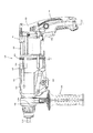
代表的な実施形態につき、図1〜図10を参照して説明する。本実施形態は、往復動式作業工具の一例として電動式のハンマドリルを用いて説明する。図1に示すように、ハンマドリル101は、本体部103と、ハンドル109と、ハンマビット119を主体として構成されている。図2および図3に示すように、本体部103の先端領域(図2の左側)にツールホルダ137が設けられており、ハンマビット119はツールホルダ137に着脱可能に取付けられる。ハンドル109のグリップ部151は、本体部103の先端領域とは反対側の後方領域に設けられている。
A representative embodiment will be described with reference to FIGS. The present embodiment will be described using an electric hammer drill as an example of a reciprocating work tool. As shown in FIG. 1, the
[駆動機構]
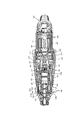
図2〜図4に示すように、本体部103は、駆動モータ111を収容したモータハウジング105と、運動変換機構113、打撃要素115及び動力伝達機構117を収容したギアハウジング107を主体として構成されている。ギアハウジング107は、先端領域にツールホルダ137を保持するベアリング137aを支持するためのベアリング支持部107aと、ギアハウジング107の内部と外部を連通する開口部107bを有している。駆動モータ111は、本発明における「モータ」に対応する実施構成例である。また、運動変換機構113、打撃要素115及び動力伝達機構117が、本発明における「駆動機構」に対応する実施構成例である。また、本体部103が、本発明における「本体部」に対応する実施構成例である。
[Drive mechanism]
As shown in FIGS. 2 to 4, the
駆動モータ111は、回転軸線がハンマビット119の長軸方向と平行になるように配置されている。駆動モータ111の前方には、冷却ファン112が駆動モータ111の回転軸に取り付けられている。すなわち、冷却ファン112は、ハンマビット119の長軸方向に関して、駆動機構と駆動モータ111の間に設けられている。したがって、駆動モータ111の駆動によって、冷却ファン112が回転し、冷却風が発生する。この冷却ファン112は、遠心ファンとして形成されている。そのため、ギアハウジング107内部を流通した冷却風が、冷却ファン112に対応した位置であるギアハウジング107の側面に設けられたギアハウジング107の開口部107bから排出される。駆動モータ111の回転出力は、駆動モータ111の前方に配置された運動変換機構113によって直線動作に変換されて打撃要素115に伝達され、ハンマビット119の長軸方向(図1における左右方向)の衝撃力を発生させる。また、駆動モータ111の回転出力は、駆動モータ111の前方に配置された動力伝達機構117によって減速されてハンマビット119に伝達され、ハンマビット119を周方向に回転させる。駆動モータ111は、ハンドル109に配置されたトリガ109aの引き操作によって通電駆動される。なお説明の便宜上、ハンマビット119側を前、ハンドル109側を後という。
The
運動変換機構113は、中間軸125と、揺動リング129と、筒状ピストン131を主体として構成されている。中間軸125は、駆動モータ111によって回転される。揺動リング129は、中間軸125の回転に伴い、回転体127を介してハンマビット119の長軸方向に搖動される。筒状ピストン131は、揺動リング129の揺動に伴い、ハンマビット119の長軸方向に直線状に往復移動される。
The
動力伝達機構117は、複数のギアからなるギア減速機構を主体として構成されている。このギア減速機構は、中間軸125と一体に回転する小径ギア133、小径ギア133と噛み合い係合する大径ギア135を有する。動力伝達機構117は、駆動モータ111の回転をツールホルダ137に伝達する。ツールホルダ137は、ベアリング保持部107aに支持されたベアリング137aによって回転可能に保持されている。これにより、ツールホルダ137が回転され、ツールホルダ137に保持されたハンマビット119が回転される。なお、ベアリング保持部107aは、アルミなどの金属製の円筒状部材として形成されている。
The
打撃要素115は、ストライカ143と、インパクトボルト145を主体として構成されている。ストライカ143は、筒状ピストン131内に摺動可能に配置された打撃子として構成されている。インパクトボルト145は、ツールホルダ137内に摺動可能に配置された中間子として構成されている。ストライカ143は、筒状ピストン131の摺動に伴う空気室131aの空気バネ(圧力変動)を介して駆動され、インパクトボルト145に衝突する。これにより、ハンマビット119が打撃力を発生する。このインパクトボルト145が、本発明における「可動部材」に対応する実施構成例である。
The
上記のハンマドリル101においては、駆動モータ111が通電駆動されると、駆動モータ111の回転が運動変換機構113を介して直線運動に変換された後、打撃要素115を介してハンマビット119に伝達される。これにより、ハンマビット119が打撃動作する。また、駆動モータ111の回転は、動力伝達機構117を介してハンマビット119に伝達される。これにより、ハンマビット119は、長軸方向の打撃動作と周方向の回転動作を行い、被加工材にハンマドリル作業を遂行する。
In the
なお、図1に示すように、ハンマドリル101は、作業モードを切替えるためのモード切替スイッチ110を備えている。そして、作業者がモード切替スイッチ110を操作することにより、作業モードとしてのハンマドリルモードとドリルモードが切り替えられる。ハンマドリルモードにおいては、ハンマビット119が打撃動作と回転動作を行う。ドリルモードにおいては、ハンマビット119が回転動作のみを行う。
As shown in FIG. 1, the
[ハンドル]
図4に示すように、ハンドル109は、作業者がハンマドリル101を保持するための樹脂製のメインハンドルとして形成されており、ハンドル後側部分150とハンドル前側部分155を主体として構成されている。ハンドル後側部分150は、作業者が把持するグリップ部151と、グリップ部151の前方に配置された円筒状のハウジング部152を主体として構成されている。グリップ部151は、ハウジング部152の後端部からハンマビット119の長軸方向に交差する下方に向かって延在するように設けられている。グリップ部151の先端部は、自由端として構成され、駆動モータ111に電気を供給するための電源ケーブルが設けられている。なお、ハウジング部152には、前方に突出する係合凸部153が設けられている。このグリップ部151が、本発明における「把持部」に対応する実施構成例である。
[handle]
As shown in FIG. 4, the
ハンドル前側部分155は、補助ハンドル190が取り付けられる補助ハンドル装着部156と、補助ハンドル装着部156の後方に配置された延在部157を主体として構成されている。補助ハンドル装着部156は、ギアハウジング107のベアリング保持部107aを囲む環状部材として構成されている。すなわち、図7に示すように、ギアハウジング107の先端領域(ハンマビット119側領域)には、ベアリング保持部107aが設けられており、ベアリング保持部107aの外側には、周方向に所定間隔で複数の凸部107bが形成されている。そして、補助ハンドル装着部156には、凸部107bの外側表面と当接するように補強リング156aが設けられている。また、図4に示すように、延在部157には、係合凸部152と係合可能な係合凹部158が設けられている。この補助ハンドル装着部156が、本発明における「補助ハンドル装着部」に対応する実施構成例である。また、補強リング156aが、本発明における「環状部」に対応する実施構成例である。また、延在部157が、本発明における「連結部」に対応する実施構成例である。
The handle
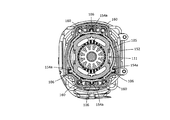
また、図4に示すように、モータハウジング105には、複数の摺動ガイド106が設けられている。複数の摺動ガイド106は、ハンマビット119の長軸方向周りの周方向に関して、モータハウジング105(駆動モータ111)の外周の複数の位置に配置されている。また、摺動ガイド106は、ハンマビット119の長軸方向に関して、前方と後方の2箇所に配置されている。すなわち、前方の摺動ガイド106と後方の摺動ガイド106は、ハンマビット119の長軸方向周りの周方向に関して、モータハウジング105(駆動モータ111)の外周の複数の位置にそれぞれ配置されている。この摺動ガイド106は、モータハウジング105の表面に形成された樹脂製の凸部を覆う金属製のカバーで形成されている。この金属製のカバーは、炭素鋼、アルミニウム、マグネシウム、チタンなどの金属で形成されている。さらに、モータハウジング105の外周には、複数のコイルスプリング160が配置されている。この摺動ガイド106が、本発明における「金属製ガイド」に対応する実施構成例である。
As shown in FIG. 4, the
図5および図6に示すように、ハウジング部152の内周面には、それぞれの摺動ガイド106に対応して複数の凹部154aと、それぞれのコイルスプリング160に対応して複数の押圧部154bが形成されている。この凹部154aは、ハウジング部152の一部として、樹脂によって形成されている。この凹部154a(ハウジング部152)は、PA6ナイロン等の樹脂材料で形成されている。また、図2に示すように、凹部154aの後端部には、摺動ガイド106と当接可能な当接部154cが形成されている。さらに、補助ハンドル装着部156の前端部には、ギアハウジング107の前端部と当接可能な当接部159aが形成されている。また、図4に示すように、補助ハンドル装着部156には、貫通孔159bが形成されている。この凹部154aが、本発明における「樹脂製ガイド」に対応する実施構成例である。
As shown in FIGS. 5 and 6, a plurality of
以上のハンドル109は、図1〜図3に示すように、ハンドル後側部分150が本体部103に対して後方から移動され、ハンドル前側部分155が本体部130に対して前方から移動されて、係合凸部153と係合凹部158によって連結されることで、ハンドル109が、本体部103の外側に組み付けられる。すなわち、ハンドル109は、ハウジング部152が、モータハウジング105を覆うように配置され、延在部157が、ギアハウジング107に沿うように配置される。この延在部157は、ギアハウジング107との間に、開口部107bから補助ハンドル装着部156の貫通孔159bまでの冷却風流路157Aを形成している。すなわち、延在部157は、ハンマドリル119の長軸方向に直交する断面に関して、略U字状の断面形状を有している。これにより、ギアハウジング107の側面に形成された開口部107bから、ハンマビット119が装着されるギアハウジング107の先端領域に至る冷却風流路157Aが形成されている。また、凹部154aが摺動ガイド106に係合し、押圧部154bがコイルスプリング160を押圧するように、ハウジング部152がモータハウジング105の外側に配置される。すなわち、コイルスプリング160は、一端がモータハウジング105に当接し、他端がハウジング部152の押圧部154bに当接して、ハンドル後側部分150を付勢した状態で支持される。ハンドル後側部分150はコイルスプリング160によって後方に向かって押圧されており、このときハンドル前側部分155の当接部159aがギアハウジング107の前端部に当接する。これにより、ハンドル109の後方への移動が規制される。このコイルスプリング160が、本発明における「付勢部材」に対応する実施構成例である。また、ハンドル109が、本発明における「メインハンドル」に対応する実施構成例である。
1-3, the handle
ギアハウジング107とハンドル後側部分150の間には、蛇腹部材108が配置されている。この蛇腹部材108は、ギアハウジング107を囲むように配置された環状部材であり、ハンマビット119の長軸方向に伸縮可能に形成されている。これにより、ハンマビット119の長軸方向に関して、ギアハウジング107に対するハンドル109の相対移動が許容される。また、蛇腹部材108は、本体部103とハンドル109の間の隙間を塞ぐシール部材として機能する。この蛇腹部材108が、本発明における「シール部材」に対応する実施構成例である。
A bellows
[補助ハンドル]
図7に示すように、補助ハンドル190は、ハンドル109の補助ハンドル装着部156に取り付けられるように構成されている。 補助ハンドル190は、把持部191と装着部195を主体として構成されている。把持部191は、グリップ部192、フランジ部193およびボルト194を備えている。グリップ部192は、樹脂製の略円筒状部材であり、作業者に把持されるように構成されている。フランジ部193は、グリップ部192の一端側に設けられおり、ボルト194が当該フランジ部193から突出するように設けられている。装着部195は、係合バンド196、ナット197およびバンド保持部198を備えている。係合バンド196は、環状に形成されたバンド状部材であり、バンド状部材の端部は、ナット197に連結されている。係合バンド196の外側には、バンド保持部198が形成されている。このバンド保持部198の中央領域には、ボルト194が貫通する貫通孔が形成されている。
[Auxiliary handle]
As shown in FIG. 7, the
以上の補助ハンドル190は、グリップ部191をグリップ部191の軸方向周りの周方向に回転させることで、ボルト194とナット197が係合する。これにより、ナット197とフランジ部193の距離が変化する。したがって、係合バンド196をハンドル109の補助ハンドル装着部156の外側に配置した状態で、グリップ部191を周方向における一方向に回転させることで、係合バンド196が補助ハンドル装着部156を外側から締め付ける。このとき、バンド保持部198が係合バンド196とフランジ部193の間に介在して、補助ハンドル190が補助ハンドル装着部156に装着される。すなわち、補助ハンドル190は、ハンドル109の補助ハンドル装着部156の外周を囲むように取り付けられる。一方、グリップ部191を他方向に回転させることで、係合バンド196が補助ハンドル装着部156に対して緩められる。これにより、補助ハンドル190が補助ハンドル装着部156から取り外される。
The
[ハンマドリルの動作]
以上のハンマドリル110においては、作業者がトリガ109aを引くことで、駆動モータ111が通電されて駆動される。これにより、モード切替スイッチ110で選択された駆動モードに基づいて、ハンマ作業あるいはハンマドリル作業が行われる。ハンマドリル101の作業時には、本体部103に、主としてハンマビット119の長軸方向の振動が発生する。一方、ハンドル109は、本体部103に対してハンマビット119の長軸方向に相対可能であるため、作業時に生じる振動に応じてハンドル109は、ハンマビット119の長軸方向に移動する。
[Hammer drill operation]
In the
具体的には、図1〜図3および図8〜図10に示すように、本体部103とハンドル109は、ハンマビット119の長軸方向に関して互いに相対移動する。図1〜図3には、本体部103に対してハンドル109が相対的に後方に位置したハンマドリル101が示される。また、図8〜図10には、本体部103に対してハンドル109が相対的に前方に位置したハンマドリル101が示される。
Specifically, as shown in FIGS. 1 to 3 and FIGS. 8 to 10, the
図1〜図3に示すように、ハンドル109は、コイルスプリング160(図4、図5参照)の後方への付勢力と、当接部159aとギアハウジング107の前端部の当接によって、本体部103とハウジング部152が距離D離れた後方位置に配置される。すなわち、蛇腹部材108が長さDで本体部103とハウジング部152の間に保持される。このとき、ハンドル109の一部である補助ハンドル装着部156に補助ハンドル190が取り付けられているため、補助ハンドル190はハンドル109と共に後方位置に位置する。この当接部159aが、本発明における「当接部」に対応する実施構成例である。また、モータハウジング105およびギアハウジング107が、本発明における「ハウジング部材」に対応する実施構成例である。
As shown in FIGS. 1 to 3, the
一方、図8〜図10に示すように、ハンドル109は、コイルスプリング160に付勢された状態で、当該コイルスプリング160の付勢力に抗して前方位置に配置される。この前方位置においては、当接部154cと摺動ガイド106の後端部の当接によって、本体部103とハウジング部152は、距離Dよりも短い距離D1で保持される。すなわち、蛇腹部材108が長さD1で本体部103とハウジング部152の間に保持される。このとき、補助ハンドル190はハンドル109と共に前方位置に位置する。この摺動ガイド106の後端部が、本発明における「規定部」に対応する実施構成例である。
On the other hand, as shown in FIGS. 8 to 10, the
摺動ガイド106および凹部154aは、ハンマビット119の長軸方向と平行に延在するように形成されている。これにより、モータハウジング105の摺動ガイド106とハンドル後側部分150の凹部154aの係合によって、ハンドル109の前方位置と後方位置の間の移動方向が、ハンマビット119の長軸方向と平行に設定されている。また、補助ハンドル装着部156の補強リング156aがギアハウジング107の凸部107bに対して摺動することで、補助ハンドル装着部156の移動方向が、ハンマビット119の長軸方向と平行に設定されている。この摺動ガイド106および凹部154aが、本発明における「ガイド要素」に対応する実施構成例である。すなわち、摺動ガイド106と凹部154aが、本発明における「一対のガイド要素構成部材」に対応する実施構成例である。また、補強リング156aと凸部107bが本発明における「ガイド部」に対応する実施構成例である。
The sliding
以上の通り、作業時に生じるハンマビット119の長軸方向の振動によって、ハンドル109は、コイルスプリング160に付勢された状態で、前方位置と後方位置を移動する。これにより、コイルスプリング160の伸縮によって、振動による運動エネルギが吸収され、本体部103からハンドル109への振動の伝達が低減される。
As described above, the
また、冷却ファン112の回転によって発生した冷却風は、開口部107bを通過して、ギアハウジング107の内側から外側に排出される。さらに、冷却風は、ギアハウジング107と延在部157の間の冷却風流路157Aを通り、金属製のベアリング保持部107aの外側を通過した後に、補助ハンドル装着部156の貫通孔159bから外部へ排出される。このとき、金属製のベアリング保持部107aの外側を冷却風が通過することで、ベアリング保持部107aに保持されたベアリング137aが冷却される。このとき、図3および図10に示すように、ハンドル109が前方位置および後方位置のいずれの位置に位置した場合であっても、ハンドル109が開口部107bを塞がない。すなわち、開口部107bの開口面積は、ハンドル109の移動によって変動しない。したがって、冷却風が通過する流路に関して、流動抵抗の変動が抑制される。
The cooling air generated by the rotation of the cooling
以上の本実施形態によれば、摺動ガイド106がハンドル109をハンマビット119の長軸方向にガイドする。したがって、主として長軸方向に振動が生じるハンマドリル101において、振動の方向とハンドル109の移動方向が一致するため、ハンドル109への振動伝達が効果的に抑制される。また、本体部103のモータハウジング105に駆動モータ111が収容されているため、ハンドル109が軽量化される。したがって、コイルスプリング160による振動エネルギの吸収量を大きくすることなく、ハンドル109の振動が効果的に低減される。また、駆動モータ111が運動変換機構113や動力伝達機構117に対して相対移動しないように配置されている。したがって、駆動モータ111の動力を運動変換機構113や動力伝達機構117に伝達するための特殊な伝達部材を設ける必要がない。
According to the present embodiment described above, the sliding
また、本実施形態によれば、ハンマビット119の長軸周りの周方向に関して、摺動ガイド106が複数の位置に配置されている。そのため、ハンマビット119の長軸方向以外の方向へのハンドル109の移動が抑制される。その結果、ハンドル109が本体部103に対して移動するハンマドリル101の操作性が向上する。
Further, according to the present embodiment, the sliding
また、本実施形態によれば、金属製の摺動ガイド106と樹脂製の凹部154aによってハンドル109の移動が案内される。すなわち、異種材料間の摺動によってハンドル109が移動される。したがって、摺動ガイド106と凹部154aの間の摺動抵抗が低減され、ハンドル109がスムーズに移動する。これにより、ハンドル109への振動伝達が効果的に低減される。
Further, according to the present embodiment, the movement of the
また、本実施形態によれば、ハンドル後側部分150とハンドル前側部分155が一体に同じ方向に移動する。そのため、ハンドル後側部分150のグリップ部151と、ハンドル前側部分155の補助ハンドル装着部156に装着された補助ハンドル190の距離が一定に保持される。したがって、グリップ部151と補助ハンドル190を把持した作業者の操作性が向上する。
Further, according to the present embodiment, the handle
また、本実施形態によれば、延在部157が補助ハンドル装着部156とハウジング部152を連結するだけでなく、冷却風流路157Aを形成する。したがって、ツールホルダ137を保持するベアリング137aを冷却するための冷却風流路を形成するための別の部材を設ける必要がない。したがって、ハンマドリル101の部品点数が少なくなる。
Further, according to the present embodiment, the extending
また、本実施形態によれば、複数のコイルスプリング160が、ハンマビット119の長軸方向周りの周方向に関して、複数の位置に配置されている。したがって、ハンドル109が複数のコイルスプリング160によって安定的に付勢される。その結果、複数のコイルスプリング160によって、ハンドル109への振動伝達が効果的に低減される。
Further, according to the present embodiment, the plurality of
また、本実施形態によれば、複数のコイルスプリング160と複数の摺動ガイド106は、駆動モータ111の外側において、ハンマビット119の長軸方向に関して、同じ位置に配置されているとともに、ハンマビット119の長軸方向周りの周方向に関して、異なる位置に配置されている。したがって、駆動モータ111の外側のスペースが有効に利用される。
Further, according to the present embodiment, the plurality of
また、本実施形態によれば、冷却風は、補助ハンドル装着部156とギアハウジング107の間を通過する。したがって、補助ハンドル装着部156とギアハウジング107の相対的な摺動によって生じる熱が放熱される。
Further, according to the present embodiment, the cooling air passes between the auxiliary
以上の本実施形態においては、付勢部材としてコイルスプリング160を設けたが、他の種類のバネやゴム等を設けてもよい。また、摺動ガイド160を樹脂で形成し、凹部154aを金属で形成してもよい。また、往復動式作業工具としては、ハンマドリル101に限られず、主として先端工具の長軸方向の振動が発生する作業工具であれば、ハンマやレシプロソーに本発明を適用してもよい。すなわち、先端工具を駆動する可動部材としては、先端工具と離間可能なインパクトボルトやストライカだけでなく、先端工具を直接保持して先端工具を往復移動させる部材であってもよい。
In the above-described embodiment, the
上記発明の趣旨に鑑み、本発明に係る往復動式作業工具に関しては、下記の態様が構成可能である。
(態様1)
可動部材が所定の長軸方向に往復移動して先端工具を駆動して所定の作業を行うとともに、補助ハンドルが装着可能な往復動式作業工具であって、
前記長軸方向と平行に出力軸が配置されたモータと、
前記可動部材を有し、前記出力軸に連接されて前記モータに駆動される駆動機構と、
前記モータと前記駆動機構を収容する本体部と、
前記本体部に対して相対移動可能なメインハンドルと、
前記本体部に対して前記メインハンドルが前記長軸方向にのみ移動するように前記メインハンドルを案内するガイド要素と、
前記本体部と前記メインハンドルの間に介在状に配置され、前記本体部から前記メインハンドルに対して前記長軸方向の付勢力を作用させる付勢部材と、を有し、
前記メインハンドルは、前記付勢部材に付勢された状態で、前記本体部に対して移動することで、前記本体部から前記メインハンドルへの前記所定の作業時に生じる振動の伝達が低減されるように構成されていることを特徴とする往復動式作業工具。
(態様2)
請求項1〜3のいずれか1項に記載の往復動式作業工具であって、
前記ガイド要素は、一対のガイド要素構成部材で構成されており、
複数の前記ガイド要素は、前記長軸方向に関して、複数の位置に配置されていることを特徴とする往復動式作業工具。
(態様3)
請求項9に記載の往復動式作業工具であって、
前記環状部は、補助ハンドルから当該環状部の径方向に力が作用されて、当該補助ハンドルが取り付けられるように構成されていることを特徴とする往復動式作業工具。
(態様4)
請求項10に記載の往復動式作業工具であって、
前記メインハンドルは、
前記長軸方向に関して、前記先端工具側から前記先端工具とは反対側に向かって前記補助ハンドル装着部が移動されて、前記本体部の前方領域に配置され、
前記長軸方向に関して、前記先端工具とは反対側から前記先端工具側に向かって前記把持部が移動されて、前記本体部の後方領域に配置され、
前記前方領域に配置された前記補助ハンドル装着部と、前記後方領域に配置された前記把持部が、前記連結部を介して連結されて組み付けられることを特徴とする往復動式作業工具。
(態様5)
請求項12に記載の往復動式作業工具であって、
前記付勢部材は、少なくとも3つの前記付勢要素で構成されていることを特徴とする往復動式作業工具。
In view of the gist of the invention, the following modes can be configured for the reciprocating work tool according to the invention.
(Aspect 1)
A movable member reciprocates in a predetermined long axis direction to drive a tip tool to perform a predetermined work, and a reciprocating work tool to which an auxiliary handle can be attached,
A motor in which an output shaft is arranged in parallel with the major axis direction;
A drive mechanism having the movable member and connected to the output shaft and driven by the motor;
A main body that houses the motor and the drive mechanism;
A main handle movable relative to the main body,
A guide element for guiding the main handle so that the main handle moves only in the long axis direction with respect to the main body portion;
An urging member that is disposed between the main body and the main handle, and that exerts an urging force in the major axis direction on the main handle from the main body;
The main handle is moved with respect to the main body while being urged by the urging member, so that transmission of vibration generated during the predetermined operation from the main body to the main handle is reduced. A reciprocating work tool characterized by being configured as described above.
(Aspect 2)
The reciprocating work tool according to any one of claims 1 to 3,
The guide element is composed of a pair of guide element constituent members,
A plurality of the guide elements are arranged at a plurality of positions with respect to the major axis direction.
(Aspect 3)
The reciprocating work tool according to claim 9,
The reciprocating work tool is characterized in that the annular portion is configured so that a force is applied from the auxiliary handle in the radial direction of the annular portion to attach the auxiliary handle.
(Aspect 4)
The reciprocating work tool according to claim 10,
The main handle is
With respect to the major axis direction, the auxiliary handle mounting portion is moved from the tip tool side toward the opposite side of the tip tool, and is arranged in a front region of the main body portion,
With respect to the long axis direction, the grip portion is moved from the side opposite to the tip tool toward the tip tool side, and is arranged in a rear region of the main body portion,
A reciprocating work tool characterized in that the auxiliary handle mounting portion arranged in the front region and the gripping portion arranged in the rear region are connected and assembled via the connecting portion.
(Aspect 5)
The reciprocating work tool according to claim 12,
The urging member is composed of at least three urging elements, and is a reciprocating work tool.
(本実施形態の各構成要素と本発明の各構成要素の対応関係)
本実施形態の各構成要素と本発明の各構成要素の対応関係を以下の通り示す。なお、本実施形態は、本発明を実施するための形態の一例を示すものであり、本発明は、本実施形態の構成に限定されるものではない。
ハンマドリル101が、本発明の「往復動式作業工具」に対応する構成の一例である。
駆動モータ111が、本発明の「モータ」に対応する構成の一例である。
運動変換機構113が、本発明の「駆動機構」に対応する構成の一例である。
打撃要素115が、本発明の「駆動機構」に対応する構成の一例である。
動力伝達機構117が、本発明の「駆動機構」に対応する構成の一例である。
インパクトボルト145が、本発明の「可動部材」に対応する構成の一例である。
ストライカ143が、本発明の「可動部材」に対応する構成の一例である。
本体部103が、本発明の「本体部」に対応する構成の一例である。
モータハウジング105が、本発明の「本体部」に対応する構成の一例である。
ギアハウジング107が、本発明の「本体部」に対応する構成の一例である。
ハンドル109が、本発明の「メインハンドル」に対応する構成の一例である。
摺動ガイド106が、本発明の「ガイド要素」に対応する構成の一例である。
摺動ガイド106が、本発明の「金属製ガイド」に対応する構成の一例である。
摺動ガイド106が、本発明の「ガイド要素構成部材」に対応する構成の一例である。
凹部154aが、本発明の「ガイド要素」に対応する構成の一例である。
凹部154aが、本発明の「樹脂製ガイド」に対応する構成の一例である。
凹部154aが、本発明の「ガイド要素構成部材」に対応する構成の一例である。
コイルスプリング160が、本発明の「付勢部材」に対応する構成の一例である。
当接部154cが、本発明の「規定部」に対応する構成の一例である。
グリップ部151が、本発明の「把持部」に対応する構成の一例である。
補助ハンドル装着部156が、本発明の「補助ハンドル装着部」に対応する構成の一例である。
延在部157が、本発明の「連結部」に対応する構成の一例である。
補強リング156aが、本発明の「環状部」に対応する構成の一例である。
蛇腹部材108が、本発明の「シール部材」に対応する構成の一例である。
(Correspondence between each component of this embodiment and each component of the present invention)
The correspondence between each component of the present embodiment and each component of the present invention is shown as follows. In addition, this embodiment shows an example of the form for implementing this invention, and this invention is not limited to the structure of this embodiment.
The
The
The
The
The
The
The
The
The
The
The
The sliding
The sliding
The sliding
The
The
The
The
The
The
The auxiliary
The extending
The reinforcing
The
101 ハンマドリル
103 本体部
105 モータハウジング
106 摺動ガイド
107 ギアハウジング
107a ベアリング保持部
107b 開口部
108 蛇腹部材
109 ハンドル
109a トリガ
110 モード切替スイッチ
111 駆動モータ
112 冷却ファン
113 運動変換機構
115 打撃要素
117 動力伝達機構
119 ハンマビット
125 中間軸
127 回転体
129 揺動リング
131 筒状ピストン
131a 空気室
133 小径ギア
135 大径ギア
137 ツールホルダ
137a ベアリング
143 ストライカ
145 インパクトボルト
150 ハンドル後側部分
151 グリップ部
152 ハウジング部
153 係合凸部
154a 凹部
154b 押圧部
154c 当接部
155 ハンドル前側部分
156 補助ハンドル装着部
156a 補強リング
157 延在部
157A 冷却風流路
158 係合凹部
159a 当接部
159b 貫通孔
160 コイルスプリング
190 補助ハンドル
191 把持部
192 グリップ部
193 フランジ部
194 ボルト
195 装着部
196 係合バンド
197 ナット
198 バンド保持部
DESCRIPTION OF
Claims (13)
前記長軸方向と平行に出力軸が配置されたモータと、
前記可動部材を有し、前記出力軸に連接されて前記モータに駆動される駆動機構と、
前記モータと前記駆動機構を収容する本体部と、
前記本体部に対して相対移動可能なメインハンドルと、
前記本体部に対して前記メインハンドルが前記長軸方向にのみ移動するように前記メインハンドルを案内するガイド要素と、
前記本体部から前記メインハンドルに対して前記長軸方向の付勢力を作用させる付勢部材と、を有し、
前記メインハンドルは、前記付勢部材に付勢された状態で、前記本体部に対して移動することで、前記本体部から前記メインハンドルへの、所定の作業時に生じる振動の伝達が低減されるように構成されていることを特徴とする往復動式作業工具。 A reciprocating work tool in which a movable member reciprocates in a predetermined long axis direction to drive a tip tool,
A motor in which an output shaft is arranged in parallel with the major axis direction;
A drive mechanism having the movable member and connected to the output shaft and driven by the motor;
A main body that houses the motor and the drive mechanism;
A main handle movable relative to the main body,
A guide element for guiding the main handle so that the main handle moves only in the long axis direction with respect to the main body portion;
An urging member that applies an urging force in the longitudinal direction from the main body portion to the main handle,
The main handle moves with respect to the main body while being urged by the urging member, so that transmission of vibrations generated during a predetermined operation from the main body to the main handle is reduced. A reciprocating work tool characterized by being configured as described above.
前記モータは円筒状に形成されており、
前記ガイド要素は、前記モータの径方向に関して、前記モータの外表面よりも外側の領域に配置されていることを特徴とする往復動作業工具。 The reciprocating work tool according to claim 1,
The motor is formed in a cylindrical shape,
The reciprocating tool according to claim 1, wherein the guide element is arranged in a region outside the outer surface of the motor with respect to a radial direction of the motor.
前記ガイド要素は、一対のガイド要素構成部材で構成されており、
複数の前記ガイド要素が、前記長軸方向周りの周方向に関して、複数の位置に配置されていることを特徴とする往復動式作業工具。 The reciprocating work tool according to claim 1 or 2,
The guide element is composed of a pair of guide element constituent members,
A reciprocating work tool, wherein the plurality of guide elements are arranged at a plurality of positions in the circumferential direction around the major axis direction.
前記一対のガイド要素構成部材は、前記本体部と前記メインハンドルのうちの一方の構成要素に設けられた金属製ガイドと、前記本体部と前記メインハンドルのうちの他方の構成要素に設けられた樹脂製ガイドで構成されていることを特徴とする往復動式作業工具。 The reciprocating work tool according to claim 3,
The pair of guide element constituent members are provided on a metal guide provided on one constituent element of the main body part and the main handle, and on the other constituent element of the main body part and the main handle. A reciprocating work tool comprising a resin guide.
前記一対のガイド要素構成部材は、前記本体部と前記メインハンドルのうちの一方の構成要素に設けられ、前記長軸方向に延在する凸部と、前記本体部と前記メインハンドルのうちの他方の構成要素に設けられ、前記長軸方向に延在する凹部で構成されており、
前記凸部と前記凹部が係合して摺動することで、前記メインハンドルが前記長軸方向にのみ移動するように案内されるように構成されていることを特徴とする往復動式作業工具。 The reciprocating work tool according to claim 3 or 4,
The pair of guide element constituent members are provided on one constituent element of the main body part and the main handle, the convex part extending in the major axis direction, and the other of the main body part and the main handle. Provided in the component, and is constituted by a concave portion extending in the major axis direction,
A reciprocating work tool characterized in that the main handle is guided so as to move only in the longitudinal direction when the convex portion and the concave portion engage and slide. .
前記ガイド要素は、前記長軸方向に関して、前記本体部に対する前記メインハンドルの移動量を規定する規定部を有することを特徴とする往復動式作業工具。 The reciprocating work tool according to any one of claims 1 to 5,
The reciprocating work tool, wherein the guide element has a defining portion that defines a movement amount of the main handle with respect to the main body portion with respect to the major axis direction.
前記メインハンドルは、作業者に把持される把持部と、補助ハンドルが着脱可能に装着される補助ハンドル装着部を有し、
前記把持部と前記補助ハンドル装着部は、前記長軸方向に関して、前記本体部に対して相対移動するように構成されていることを特徴とする往復動式作業工具。 The reciprocating work tool according to any one of claims 1 to 6,
The main handle has a grip portion to be gripped by an operator and an auxiliary handle mounting portion to which the auxiliary handle is detachably mounted,
The reciprocating work tool is characterized in that the grip portion and the auxiliary handle mounting portion are configured to move relative to the main body portion in the major axis direction.
前記本体部に対して前記補助ハンドル装着部を案内するガイド部を有することを特徴とする往復動式作業工具。 The reciprocating work tool according to claim 7,
A reciprocating work tool comprising a guide portion for guiding the auxiliary handle mounting portion with respect to the main body portion.
前記補助ハンドル装着部は、前記本体部を囲むように形成された環状部を有しており、
前記環状部は、当該環状部の外周部に補助ハンドルが取り付けられるように構成されていることを特徴とする往復動式作業工具。 The reciprocating work tool according to claim 7 or 8,
The auxiliary handle mounting part has an annular part formed so as to surround the main body part,
The reciprocating work tool is characterized in that the annular portion is configured such that an auxiliary handle is attached to an outer peripheral portion of the annular portion.
前記メインハンドルは、前記把持部と前記補助ハンドル装着部を連結する連結部を有し、
前記補助ハンドル装着部は、前記長軸方向に関して、先端工具側に配置され、
前記把持部は、前記長軸方向に関して、前記補助ハンドル装着部に対して先端工具とは反対側に配置されるように構成されていることを特徴とする往復動式作業工具。 The reciprocating work tool according to any one of claims 7 to 9,
The main handle has a connecting portion for connecting the grip portion and the auxiliary handle mounting portion,
The auxiliary handle mounting portion is disposed on the tip tool side with respect to the long axis direction,
The reciprocating work tool is characterized in that the grip portion is arranged on the side opposite to the tip tool with respect to the auxiliary handle mounting portion with respect to the major axis direction.
前記本体部は、前記モータと前記駆動機構を収容するハウジング部材を有しており、
前記補助ハンドル装着部は、前記ハウジング部材と当接する当接部を有しており、
前記当接部が、前記長軸方向に関して、先端工具から離れる方向への前記メインハンドルの移動量を規定するように構成されていることを特徴とする往復動式作業工具。 The reciprocating work tool according to claim 10,
The main body has a housing member that houses the motor and the drive mechanism,
The auxiliary handle mounting portion has a contact portion that contacts the housing member,
The reciprocating work tool is characterized in that the abutment portion is configured to define a movement amount of the main handle in a direction away from the tip tool with respect to the major axis direction.
前記付勢部材は、複数の付勢要素で構成されており、
複数の前記付勢要素は、前記長軸方向周りの周方向に関して、互いに異なる位置に配置されていることを特徴とする往復動式作業工具。 The reciprocating work tool according to any one of claims 1 to 11,
The biasing member is composed of a plurality of biasing elements,
The reciprocating work tool, wherein the plurality of biasing elements are arranged at different positions with respect to a circumferential direction around the major axis direction.
前記メインハンドルと前記本体部の間の隙間を塞ぐシール部材が設けられていることを特徴とする往復動式作業工具。 The reciprocating work tool according to any one of claims 1 to 12,
A reciprocating work tool characterized in that a seal member for closing a gap between the main handle and the main body is provided.
Priority Applications (4)
| Application Number | Priority Date | Filing Date | Title |
|---|---|---|---|
| JP2013244446A JP6334144B2 (en) | 2013-11-26 | 2013-11-26 | Reciprocating work tool |
| CN201410505327.4A CN104669219B (en) | 2013-11-26 | 2014-09-26 | Reciprocating power tool |
| EP14194519.6A EP2875907B1 (en) | 2013-11-26 | 2014-11-24 | Power tool |
| US14/554,890 US9815185B2 (en) | 2013-11-26 | 2014-11-26 | Power tool |
Applications Claiming Priority (1)
| Application Number | Priority Date | Filing Date | Title |
|---|---|---|---|
| JP2013244446A JP6334144B2 (en) | 2013-11-26 | 2013-11-26 | Reciprocating work tool |
Publications (2)
| Publication Number | Publication Date |
|---|---|
| JP2015100897A true JP2015100897A (en) | 2015-06-04 |
| JP6334144B2 JP6334144B2 (en) | 2018-05-30 |
Family
ID=52013833
Family Applications (1)
| Application Number | Title | Priority Date | Filing Date |
|---|---|---|---|
| JP2013244446A Active JP6334144B2 (en) | 2013-11-26 | 2013-11-26 | Reciprocating work tool |
Country Status (4)
| Country | Link |
|---|---|
| US (1) | US9815185B2 (en) |
| EP (1) | EP2875907B1 (en) |
| JP (1) | JP6334144B2 (en) |
| CN (1) | CN104669219B (en) |
Cited By (2)
| Publication number | Priority date | Publication date | Assignee | Title |
|---|---|---|---|---|
| JP2020104238A (en) * | 2018-12-28 | 2020-07-09 | 株式会社マキタ | Striking tool |
| DE102022102194A1 (en) | 2021-02-04 | 2022-08-04 | Makita Corporation | POWER TOOL WITH A HAMMER MECHANISM |
Families Citing this family (19)
| Publication number | Priority date | Publication date | Assignee | Title |
|---|---|---|---|---|
| WO2015061370A1 (en) | 2013-10-21 | 2015-04-30 | Milwaukee Electric Tool Corporation | Adapter for power tool devices |
| JP6478409B2 (en) * | 2015-08-18 | 2019-03-06 | 株式会社マキタ | Work tools |
| CN105058328A (en) * | 2015-08-30 | 2015-11-18 | 安徽省葛根生产力促进中心有限公司 | Electric hammer building device with foldable shoulder supporting frame |
| US11052525B2 (en) * | 2016-03-03 | 2021-07-06 | Makita Corporation | Hammer drill |
| DE102017123102A1 (en) * | 2016-11-04 | 2018-05-09 | Makita Corporation | power tool |
| AU2018312343A1 (en) | 2017-07-31 | 2020-02-13 | Milwaukee Electric Tool Corporation | Rotary power tool |
| US10864609B2 (en) * | 2017-09-28 | 2020-12-15 | Makita Corporation | Dust collector |
| US11597061B2 (en) * | 2018-12-10 | 2023-03-07 | Milwaukee Electric Tool Corporation | High torque impact tool |
| US20220331941A1 (en) * | 2019-06-13 | 2022-10-20 | Koki Holdings Co., Ltd. | Electric working machine |
| US11826891B2 (en) | 2019-10-21 | 2023-11-28 | Makita Corporation | Power tool having hammer mechanism |
| JP7360891B2 (en) * | 2019-10-21 | 2023-10-13 | 株式会社マキタ | hammer drill |
| US11926030B2 (en) * | 2020-08-24 | 2024-03-12 | Makita Corporation | Power tool having hammer mechanism |
| JP2022128006A (en) | 2021-02-22 | 2022-09-01 | 株式会社マキタ | impact tool |
| US11642769B2 (en) * | 2021-02-22 | 2023-05-09 | Makita Corporation | Power tool having a hammer mechanism |
| JP2022127768A (en) * | 2021-02-22 | 2022-09-01 | 株式会社マキタ | impact tool |
| US11583992B2 (en) | 2021-03-25 | 2023-02-21 | Milwaukee Electric Tool Corporation | Side handle for power tool |
| EP4319944A1 (en) | 2021-04-07 | 2024-02-14 | Milwaukee Electric Tool Corporation | Impact power tool |
| US20230415321A1 (en) | 2022-06-24 | 2023-12-28 | Makita Corporation | Power tool having a hammer mechanism |
| US11951606B1 (en) | 2022-10-14 | 2024-04-09 | Snap-On Incorporated | Handle and tool with integrated handle mount |
Citations (5)
| Publication number | Priority date | Publication date | Assignee | Title |
|---|---|---|---|---|
| JP2009509790A (en) * | 2005-10-04 | 2009-03-12 | ローベルト ボツシユ ゲゼルシヤフト ミツト ベシユレンクテル ハフツング | Electric machine tool |
| JP2009248241A (en) * | 2008-04-04 | 2009-10-29 | Makita Corp | Hand-held work tool |
| JP2010247239A (en) * | 2009-04-10 | 2010-11-04 | Makita Corp | Striking tool |
| JP2011000684A (en) * | 2009-06-19 | 2011-01-06 | Makita Corp | Working tool |
| JP2013151055A (en) * | 2012-01-26 | 2013-08-08 | Makita Corp | Striking tool |
Family Cites Families (5)
| Publication number | Priority date | Publication date | Assignee | Title |
|---|---|---|---|---|
| DE10034768A1 (en) * | 2000-07-18 | 2002-02-07 | Bosch Gmbh Robert | Combination electric hand tool operating as hammer drill or electric chisel, has pivoted jaw catch mechanism with blocking component in handle |
| JP4647957B2 (en) * | 2004-08-27 | 2011-03-09 | 株式会社マキタ | Work tools |
| DE102005059180A1 (en) | 2005-12-12 | 2007-06-14 | Robert Bosch Gmbh | Hand tool with a drive train and a decoupling unit |
| EP2109519B1 (en) * | 2007-02-07 | 2017-07-12 | Robert Bosch GmbH | Vibration dampening for a power tool |
| JP5502352B2 (en) * | 2009-03-23 | 2014-05-28 | 株式会社マキタ | Electric tool |
-
2013
- 2013-11-26 JP JP2013244446A patent/JP6334144B2/en active Active
-
2014
- 2014-09-26 CN CN201410505327.4A patent/CN104669219B/en active Active
- 2014-11-24 EP EP14194519.6A patent/EP2875907B1/en active Active
- 2014-11-26 US US14/554,890 patent/US9815185B2/en active Active
Patent Citations (5)
| Publication number | Priority date | Publication date | Assignee | Title |
|---|---|---|---|---|
| JP2009509790A (en) * | 2005-10-04 | 2009-03-12 | ローベルト ボツシユ ゲゼルシヤフト ミツト ベシユレンクテル ハフツング | Electric machine tool |
| JP2009248241A (en) * | 2008-04-04 | 2009-10-29 | Makita Corp | Hand-held work tool |
| JP2010247239A (en) * | 2009-04-10 | 2010-11-04 | Makita Corp | Striking tool |
| JP2011000684A (en) * | 2009-06-19 | 2011-01-06 | Makita Corp | Working tool |
| JP2013151055A (en) * | 2012-01-26 | 2013-08-08 | Makita Corp | Striking tool |
Cited By (3)
| Publication number | Priority date | Publication date | Assignee | Title |
|---|---|---|---|---|
| JP2020104238A (en) * | 2018-12-28 | 2020-07-09 | 株式会社マキタ | Striking tool |
| JP7159043B2 (en) | 2018-12-28 | 2022-10-24 | 株式会社マキタ | impact tool |
| DE102022102194A1 (en) | 2021-02-04 | 2022-08-04 | Makita Corporation | POWER TOOL WITH A HAMMER MECHANISM |
Also Published As
| Publication number | Publication date |
|---|---|
| CN104669219B (en) | 2017-05-31 |
| US20150144366A1 (en) | 2015-05-28 |
| CN104669219A (en) | 2015-06-03 |
| EP2875907A1 (en) | 2015-05-27 |
| JP6334144B2 (en) | 2018-05-30 |
| EP2875907B1 (en) | 2016-06-22 |
| US9815185B2 (en) | 2017-11-14 |
Similar Documents
| Publication | Publication Date | Title |
|---|---|---|
| JP6334144B2 (en) | Reciprocating work tool | |
| JP6309881B2 (en) | Work tools | |
| JP6105454B2 (en) | Work tools | |
| JP6325360B2 (en) | Impact tool | |
| JP6096593B2 (en) | Reciprocating work tool | |
| JP6258093B2 (en) | Impact tool | |
| JP6278830B2 (en) | Impact tool | |
| JP6441588B2 (en) | Impact tool | |
| JP2019038093A (en) | Work tool | |
| JP5294726B2 (en) | Hand-held work tool | |
| JP2010000567A (en) | Hand-held working tool | |
| WO2006041139A1 (en) | Reciprocating working tool | |
| JP2016129911A (en) | Power tool | |
| JP2017042887A (en) | Hammering tool | |
| JP6116058B2 (en) | Work tools | |
| JP5984659B2 (en) | Impact tool | |
| JP5356097B2 (en) | Impact tool | |
| JP6208061B2 (en) | Work tools | |
| JP6348337B2 (en) | Reciprocating work tool | |
| WO2020195725A1 (en) | Striking work machine | |
| JP2017042888A (en) | Impact tool | |
| JP2016093855A (en) | Impact tool |
Legal Events
| Date | Code | Title | Description |
|---|---|---|---|
| A621 | Written request for application examination |
Free format text: JAPANESE INTERMEDIATE CODE: A621 Effective date: 20160526 |
|
| A131 | Notification of reasons for refusal |
Free format text: JAPANESE INTERMEDIATE CODE: A131 Effective date: 20170315 |
|
| A977 | Report on retrieval |
Free format text: JAPANESE INTERMEDIATE CODE: A971007 Effective date: 20170316 |
|
| A521 | Request for written amendment filed |
Free format text: JAPANESE INTERMEDIATE CODE: A523 Effective date: 20170510 |
|
| A131 | Notification of reasons for refusal |
Free format text: JAPANESE INTERMEDIATE CODE: A131 Effective date: 20170711 |
|
| A521 | Request for written amendment filed |
Free format text: JAPANESE INTERMEDIATE CODE: A523 Effective date: 20170831 |
|
| A131 | Notification of reasons for refusal |
Free format text: JAPANESE INTERMEDIATE CODE: A131 Effective date: 20171023 |
|
| A521 | Request for written amendment filed |
Free format text: JAPANESE INTERMEDIATE CODE: A523 Effective date: 20171212 |
|
| TRDD | Decision of grant or rejection written | ||
| A01 | Written decision to grant a patent or to grant a registration (utility model) |
Free format text: JAPANESE INTERMEDIATE CODE: A01 Effective date: 20180424 |
|
| A61 | First payment of annual fees (during grant procedure) |
Free format text: JAPANESE INTERMEDIATE CODE: A61 Effective date: 20180426 |
|
| R150 | Certificate of patent or registration of utility model |
Ref document number: 6334144 Country of ref document: JP Free format text: JAPANESE INTERMEDIATE CODE: R150 |
|
| R250 | Receipt of annual fees |
Free format text: JAPANESE INTERMEDIATE CODE: R250 |
|
| R250 | Receipt of annual fees |
Free format text: JAPANESE INTERMEDIATE CODE: R250 |
|
| R250 | Receipt of annual fees |
Free format text: JAPANESE INTERMEDIATE CODE: R250 |