JP2015100613A - Image processing apparatus and method, and ultrasonic diagnostic apparatus - Google Patents
Image processing apparatus and method, and ultrasonic diagnostic apparatus Download PDFInfo
- Publication number
- JP2015100613A JP2015100613A JP2013244951A JP2013244951A JP2015100613A JP 2015100613 A JP2015100613 A JP 2015100613A JP 2013244951 A JP2013244951 A JP 2013244951A JP 2013244951 A JP2013244951 A JP 2013244951A JP 2015100613 A JP2015100613 A JP 2015100613A
- Authority
- JP
- Japan
- Prior art keywords
- frame
- unit
- image
- distortion amount
- image processing
- Prior art date
- Legal status (The legal status is an assumption and is not a legal conclusion. Google has not performed a legal analysis and makes no representation as to the accuracy of the status listed.)
- Pending
Links
Images


Classifications
-
- G—PHYSICS
- G06—COMPUTING OR CALCULATING; COUNTING
- G06T—IMAGE DATA PROCESSING OR GENERATION, IN GENERAL
- G06T3/00—Geometric image transformations in the plane of the image
- G06T3/02—Affine transformations
-
- G—PHYSICS
- G06—COMPUTING OR CALCULATING; COUNTING
- G06T—IMAGE DATA PROCESSING OR GENERATION, IN GENERAL
- G06T7/00—Image analysis
- G06T7/0002—Inspection of images, e.g. flaw detection
- G06T7/0012—Biomedical image inspection
-
- G—PHYSICS
- G06—COMPUTING OR CALCULATING; COUNTING
- G06T—IMAGE DATA PROCESSING OR GENERATION, IN GENERAL
- G06T11/00—Two-dimensional [2D] image generation
- G06T11/60—Creating or editing images; Combining images with text
Landscapes
- Engineering & Computer Science (AREA)
- Physics & Mathematics (AREA)
- General Physics & Mathematics (AREA)
- Theoretical Computer Science (AREA)
- Health & Medical Sciences (AREA)
- General Health & Medical Sciences (AREA)
- Medical Informatics (AREA)
- Nuclear Medicine, Radiotherapy & Molecular Imaging (AREA)
- Radiology & Medical Imaging (AREA)
- Quality & Reliability (AREA)
- Computer Vision & Pattern Recognition (AREA)
- Ultra Sonic Daignosis Equipment (AREA)
Abstract
Description
本開示は、画像処理装置および方法、並びに超音波診断装置に関し、特に、プローブが移動する場合に正確に変位検出を行うことができるようにした画像処理装置および方法、並びに超音波診断装置に関する。 The present disclosure relates to an image processing apparatus and method, and an ultrasonic diagnostic apparatus, and more particularly to an image processing apparatus and method and an ultrasonic diagnostic apparatus that can accurately detect displacement when a probe moves.
超音波を用いて組織の硬さを評価するエラストグラフィにおいては、プローブを静止した状態で、深さ方向に振動させることで組織の変位を検出している。 In elastography in which the hardness of a tissue is evaluated using ultrasonic waves, the displacement of the tissue is detected by vibrating in the depth direction while the probe is stationary.
しかしながら、プローブを動かした状態では、組織の変位を正しく検出できない。これは、変位検出で用いる対応点が動きにより移動していまうが、その補正をしていないためである。 However, when the probe is moved, the displacement of the tissue cannot be detected correctly. This is because the corresponding points used for displacement detection are moved by movement, but are not corrected.
なお、音響放射圧インパルス(ARFI)においては、所望の照射位置と実際の照射位置のずれ量の検出を行うものがある(特許文献1参照)。 Note that there is an acoustic radiation pressure impulse (ARFI) that detects a deviation amount between a desired irradiation position and an actual irradiation position (see Patent Document 1).
すなわち、プローブを動かした状態では、変位検出で用いる対応点が動きにより移動していまい、フレーム間で対応するラインが揃っていない。このため、プローブを動かした状態では、組織の変位を正しく検出できない。 That is, in a state where the probe is moved, corresponding points used for displacement detection do not move due to movement, and corresponding lines are not aligned between frames. For this reason, when the probe is moved, the displacement of the tissue cannot be detected correctly.
本開示は、このような状況に鑑みてなされたものであり、プローブが移動する場合に正確に変位検出を行うことができるものである。 The present disclosure has been made in view of such a situation, and can accurately detect displacement when a probe moves.
本開示の一側面の画像処理装置は、プローブが移動する場合に、第1のフレームと、前記第1のフレームとは異なる時刻のフレームである第2のフレームとの間のずれ量を補正するずれ量補正部と、前記第1のフレームと前記ずれ量補正部によりずれ量が補正された第2フレームとから検出された位相差に基づいて歪量を算出する歪量算出部とを備える。 The image processing apparatus according to one aspect of the present disclosure corrects a shift amount between a first frame and a second frame that is a frame at a time different from the first frame when the probe moves. A deviation amount correction unit; and a distortion amount calculation unit that calculates a distortion amount based on a phase difference detected from the first frame and a second frame in which the deviation amount is corrected by the deviation amount correction unit.
前記歪量算出部により算出された歪量を、Bモード画像に重畳する重畳部をさらに備えることができる。 The image processing apparatus may further include a superimposing unit that superimposes the distortion amount calculated by the distortion amount calculating unit on the B-mode image.
前記第1のフレームおよび前記第2のフレームは、前記Bモード画像が生成される方向に平行な方向以外の方向の画像である。 The first frame and the second frame are images in directions other than the direction parallel to the direction in which the B-mode image is generated.
前記第1のフレームおよび前記第2のフレームは、前記Bモード画像が生成される方向に平行な方向の画像である。 The first frame and the second frame are images in a direction parallel to a direction in which the B-mode image is generated.
前記第1のフレームおよび前記第2のフレームは、前記プローブが移動する方向に平行な方向の画像である。 The first frame and the second frame are images in a direction parallel to the direction in which the probe moves.
前記重畳部は、前記歪量算出部により算出された歪量を、前記歪量が算出された方向に直交する方向のBモード画像に重畳することができる。 The superimposing unit can superimpose the distortion amount calculated by the distortion amount calculating unit on a B-mode image in a direction orthogonal to the direction in which the distortion amount is calculated.
前記重畳部は、前記歪量算出部により算出された歪量を、前記歪量が算出された方向に平行する方向のBモード画像に重畳することができる。 The superimposing unit can superimpose the distortion amount calculated by the distortion amount calculating unit on a B-mode image in a direction parallel to the direction in which the distortion amount is calculated.
前記歪量算出部により算出された歪量を、被写体に関する内視鏡画像に重畳する重畳部をさらに備えることができる。 The image processing apparatus may further include a superimposing unit that superimposes the distortion amount calculated by the distortion amount calculating unit on an endoscopic image related to the subject.
本開示の一側面の画像処理方法は、画像処理装置が、プローブが移動する場合に、第1のフレームと、前記第1のフレームとは異なる時刻のフレームである第2のフレームとの間のずれ量を補正し、前記第1のフレームと前記ずれ量が補正された第2フレームとから検出された位相差に基づいて歪量を算出する。 According to an image processing method of one aspect of the present disclosure, when the image processing apparatus moves the probe, the image processing apparatus includes a first frame and a second frame that is a frame at a time different from the first frame. The amount of deviation is corrected, and the amount of distortion is calculated based on the phase difference detected from the first frame and the second frame in which the amount of deviation is corrected.
本開示の一側面の超音波診断装置は、プローブと、画像処理部とを備え、前記画像処理部は、プローブが移動する場合に、第1のフレームと、前記第1のフレームとは異なる時刻のフレームである第2のフレームとの間のずれ量を補正するずれ量補正部と、前記第1のフレームと前記ずれ量補正部によりずれ量が補正された第2フレームとから検出された位相差に基づいて歪量を算出する歪量算出部とを備える。 An ultrasonic diagnostic apparatus according to an aspect of the present disclosure includes a probe and an image processing unit, and the image processing unit has a time different from the first frame and the first frame when the probe moves. A shift amount correction unit that corrects a shift amount between the first frame and the second frame that has been corrected by the shift amount correction unit. A distortion amount calculation unit that calculates a distortion amount based on the phase difference.
前記画像処理部は、前記歪量算出部により算出された歪量を、Bモード画像に重畳する重畳部をさらに備えることができる。 The image processing unit may further include a superimposing unit that superimposes the distortion amount calculated by the distortion amount calculating unit on a B-mode image.
前記プローブは、第1の方向および第1の方向に直交する第2の方向に、それぞれ複数の圧電素子を有し、前記第1のフレームおよび前記第2のフレームは、前記Bモード画像が生成される方向に平行な方向以外の方向の画像である。 The probe has a plurality of piezoelectric elements in a first direction and a second direction orthogonal to the first direction, and the B-mode image is generated in the first frame and the second frame. It is an image in a direction other than the direction parallel to the direction to be displayed.
本開示の一側面においては、プローブが移動する場合に、第1のフレームと、前記第1のフレームとは異なる時刻のフレームである第2のフレームとの間のずれ量が補正される。そして、前記第1のフレームと前記ずれ量が補正された第2フレームとから検出された位相差に基づいて歪量が算出される。 In one aspect of the present disclosure, when the probe moves, a shift amount between the first frame and the second frame that is a frame at a time different from the first frame is corrected. Then, a distortion amount is calculated based on the phase difference detected from the first frame and the second frame in which the shift amount is corrected.
本開示によれば、変位検出を行うことができる。特に、プローブが移動する場合に正確に変位検出を行うことができる。 According to the present disclosure, displacement detection can be performed. In particular, displacement detection can be performed accurately when the probe moves.
以下、本開示を実施するための形態(以下実施の形態とする)について説明する。なお、説明は以下の順序で行う。
1.第1の実施の形態(超音波画像処理装置)
2.第2の実施の形態(コンピュータ)
Hereinafter, modes for carrying out the present disclosure (hereinafter referred to as embodiments) will be described. The description will be given in the following order.
1. First embodiment (ultrasonic image processing apparatus)
2. Second embodiment (computer)
<第1の実施の形態>
<プローブの軸と動きの例>
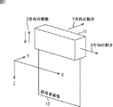
まず、図1を参照して、プローブの軸と動きについて説明する。なお、説明を簡単にするため、1Dのプローブが直方体の形状をしていることとする。
<First Embodiment>
<Example of probe axis and movement>
First, the axis and movement of the probe will be described with reference to FIG. For simplicity of explanation, it is assumed that the 1D probe has a rectangular parallelepiped shape.
プローブ11の軸として、長軸方向、短軸方向、深さ方向へ、X軸、Y軸、Z軸をそれぞれ割り当て、以下、XYZを用いて説明する。プローブ11は、複数の圧電素子が配列されて構成される。長軸方向とは、配列する圧電素子の数が短軸方向より多く、圧電素子の全長が長い方向である。短軸方向とは、配列する圧電素子の数が長軸方向より少なく、圧電素子の全長が長軸方向よりも短い方向である。深さ方向とは、超音波出力方向である深さ方向である。
As the axis of the
例えば、1Dプローブである場合に、X方向の配列されている圧電素子で受信したRF信号を並べることで超音波画像12が生成される。
For example, in the case of a 1D probe, the
なお、プローブ11の動きとして、Z方向に対しては、プローブ11からのエラストグラフィを取得するための振動がある。また、X方向とY方向に対しては、使用者の操作などによる規則的または不規則的な運動が想定される。一例として、Y方向へはスイープ動作による等速移動、X方向へは手振れなどによる不規則な移動などが考えられる。
As the movement of the
<プローブの構成例>
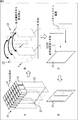
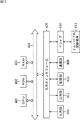
図2は、本技術において用いられるプローブの構成例を示す図である。なお、本技術においては、図1で示したY方向の動きを検知するために、Y方向に2つ以上の圧電素子(例えば、振動子)31が配列されている必要がある。すなわち、プローブ21は、1.5Dまたは2Dアレイのプローブとして構成される。なお、後述するが、使用する画像と重畳する画像の方向によっては、1Dのプローブも用いることができる。
<Example of probe configuration>
FIG. 2 is a diagram illustrating a configuration example of a probe used in the present technology. In the present technology, in order to detect the movement in the Y direction shown in FIG. 1, it is necessary that two or more piezoelectric elements (for example, vibrators) 31 are arranged in the Y direction. That is, the
図2の例においては、圧電素子31が、X方向へ8素子、Y方向へ3素子配列された1.5Dのプローブ21が示されている。
In the example of FIG. 2, a 1.5
図1において上述したように、各圧電素子31で受信したRF信号を並べることで超音波画像が生成される。図2の例においては、X方向に着目すると、8つの圧電素子31が3列に配列されているので、3枚の超音波画像(以下、X方向超音波画像と称する)23が生成される。同様に、Y方向に着目すると、3つの圧電素子31が8列に配列されているので、8枚の超音波画像(以下、Y方向超音波画像と称する)22が生成される。X方向超音波画像23は、Bモード画像生成に用いられる。
As described above with reference to FIG. 1, an ultrasonic image is generated by arranging the RF signals received by the
このように、本技術のプローブにおいては、Y方向にも超音波画像が生成されるので、それを用いてブロックマッチングができて、変位検出で用いる対応点を追跡することができる。 As described above, in the probe of the present technology, since an ultrasonic image is also generated in the Y direction, block matching can be performed using the ultrasonic image, and corresponding points used in displacement detection can be tracked.
なお、図2の例においては図示されないが、2Dアレイのプローブの場合、圧電素子は、X方向とY方向に同数配列される。 Although not shown in the example of FIG. 2, in the case of a 2D array probe, the same number of piezoelectric elements are arranged in the X and Y directions.
<本技術の概要>
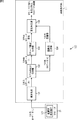
図3は、本技術を具体的に説明する図である。図3Aに示されるように、Y方向の動きがある場合が示されている。Y方向の動きを検出するためには、図3Bに示されるように、X方向の8素子分における時刻の異なる2枚(時刻tと時刻t-1の2枚)のY方向超音波画像22が用いられる。この動き検出には、例えば、ブロックマッチングを使った手法などを適用することができる。これにより、動きベクトルを求めることができる。
<Outline of this technology>
FIG. 3 is a diagram for specifically explaining the present technology. As shown in FIG. 3A, a case where there is a movement in the Y direction is shown. In order to detect the movement in the Y direction, as shown in FIG. 3B, two Y direction ultrasonic images 22 (two at time t and time t−1) having different times for eight elements in the X direction are used. Is used. For example, a technique using block matching can be applied to this motion detection. Thereby, a motion vector can be obtained.
図3の例においては、Y方向に3素子配列されているので、素子間ピッチ×2[um]の動きまで検出することが可能である。Y方向により多くの圧電素子31が並ぶほど、大きな動きの検出が可能となる。
In the example of FIG. 3, since three elements are arranged in the Y direction, it is possible to detect a movement of an element pitch × 2 [um]. The greater the number of
次に、Y方向に動くことで、フレーム間で対応するラインがずれているので、図3Bに示されるように、検出された動きベクトルを用いて、動き補償を伴う変位検出が行われる。すなわち、検出された動きベクトルを用いて、t-1の画像に対して動き補償が行われ、動き補償画像が生成される。なお、この際、動きベクトルが素子間ピッチよりも短い場合、補間処理が行われて、小数位置の画素が作られる。よって、素子間ピッチよりも小さな動きも補償可能である。 Next, since the corresponding line is shifted between frames by moving in the Y direction, displacement detection with motion compensation is performed using the detected motion vector, as shown in FIG. 3B. That is, motion compensation is performed on the t-1 image using the detected motion vector, and a motion compensated image is generated. At this time, if the motion vector is shorter than the inter-element pitch, interpolation processing is performed to create a pixel at the decimal position. Therefore, motion smaller than the pitch between elements can be compensated.
そして、時刻tの画像と時刻t-1の動き補償画像の間で、位相差検出処理を行う。例えば、位相差検出処理として、自己相関法を用いることが可能である。そして、位相差検出結果より、変位および歪量が検出される。 Then, a phase difference detection process is performed between the image at time t and the motion compensated image at time t-1. For example, an autocorrelation method can be used as the phase difference detection process. Then, displacement and distortion amount are detected from the phase difference detection result.
なお、上述したこれらの処理は、Y方向の3素子分行われる。したがって、この3素子分の結果を集約することで、X方向超音波画像23に対して、1スキャンライン分の歪量データが作成される。この集約の方法は、平均やメディアンなどがあるが、集約する方法であればどんな方法でもかまわない。また、集約でなくても、3素子分のうちのどれか1素子分(例えば、真ん中の1素子)を選択して用いる方法でもよい。
Note that these processes described above are performed for three elements in the Y direction. Therefore, by integrating the results for the three elements, distortion amount data for one scan line is created for the X-direction
さらに、動き検出補償においては、多くの素子分を用い、位相差検出処理においてそのうちの数素子分や1素子分を用いることも可能である。 Furthermore, it is possible to use many elements in motion detection compensation, and use several elements or one element among them in the phase difference detection process.
以上の処理を、X方向超音波画像23の各スキャンラインに対応する3素子を使って繰り返すことで、すべてのスキャンラインの歪量データを生成することが可能である。この歪量データは、図3Cに示されるように、X方向超音波画像23に重畳して表示される。
By repeating the above processing using three elements corresponding to each scan line of the X-direction
以上のように、動きの方向に平行な超音波画像を用いて動き検出補償をして、その結果が、動きの方向と直交する超音波画像(Bモード画像)に重畳して表示される。換言するに、Bモード画像が生成される方向に直交する超音波画像を用いて動き検出補償をして、その結果が、Bモード画像に重畳して表示される。 As described above, motion detection compensation is performed using an ultrasound image parallel to the direction of motion, and the result is displayed superimposed on the ultrasound image (B-mode image) orthogonal to the direction of motion. In other words, motion detection compensation is performed using an ultrasonic image orthogonal to the direction in which the B-mode image is generated, and the result is displayed superimposed on the B-mode image.
なお、2Dプローブの場合、例えば、X方向に8素子並び、Y方向に8素子並ぶので、Y方向に動きがあるとき、Y方向(平行方向)の画像で動きを検出補償し、Y方向(平行方向)の画像に重畳することもできる。この場合は、8素子のデータを集約することなしに、Y方向の8面分の画像に対してそれぞれ行うことができる。 In the case of a 2D probe, for example, since 8 elements are arranged in the X direction and 8 elements are arranged in the Y direction, when there is movement in the Y direction, the motion is detected and compensated for in the image in the Y direction (parallel direction). It can also be superimposed on the image in the parallel direction. In this case, it is possible to perform the processing for each of the eight images in the Y direction without collecting the data of the eight elements.
また、上記説明においてはY方向の動きを検出する例を説明したが、X方向の動きを検出することも可能である。例えば、1Dプローブの場合、X方向に動きがあるとき、X方向(平行方向)の動き検出補償し、X方向(平行方向)の画像に重畳することができる。 In the above description, the example of detecting the movement in the Y direction has been described. However, it is also possible to detect the movement in the X direction. For example, in the case of a 1D probe, when there is motion in the X direction, motion detection compensation in the X direction (parallel direction) can be performed and superimposed on an image in the X direction (parallel direction).
さらに、2Dプローブの場合、X方向に動いていて、X方向(平行方向)に動き検出補償して、Y方向(直交方向)に重畳することもできる。 Further, in the case of a 2D probe, it can be moved in the X direction, compensated for motion detection in the X direction (parallel direction), and superimposed in the Y direction (orthogonal direction).
すなわち、本技術においては、プローブが移動する場合に、異なる時刻の2フレームの間のずれ量を補正し、第1のフレームとずれ量が補正された第2フレームとの位相差を検出して、検出された位相差に基づいて、歪量を算出するようにした。 That is, in the present technology, when the probe moves, the shift amount between the two frames at different times is corrected, and the phase difference between the first frame and the second frame in which the shift amount is corrected is detected. The amount of distortion is calculated based on the detected phase difference.
これにより、プローブが動いた状態で、正確な変位検出を行うことができる。したがって、組織の硬さを正しく求めることができる。 Thus, accurate displacement detection can be performed with the probe moving. Therefore, the hardness of the tissue can be obtained correctly.
なお、本技術は、X軸、Y軸、Z軸に沿ってだけ動くものではなく、斜めに動く場合にも適用することができる。斜めに動く場合には、動きの成分をX方向とY方向に分解して、各方向で動き検出と変位検出を行い、統計処理(例えば、平均化)をした結果から歪量を求めることができる。 Note that the present technology can be applied not only to move along the X-axis, Y-axis, and Z-axis but also to move diagonally. When moving diagonally, it is possible to determine the amount of distortion from the result of statistical processing (for example, averaging) by decomposing the motion components in the X and Y directions, performing motion detection and displacement detection in each direction it can.
さらに、本技術は、プローブ21が偏心して動く(回転角度を有する動きを行う)場合にも適用可能である。
Furthermore, the present technology can also be applied when the
<プローブの偏心>
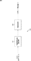
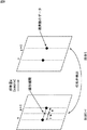
図4は、プローブの偏心について説明する図である。
<Eccentricity of probe>
FIG. 4 is a diagram for explaining the eccentricity of the probe.
プローブ21の偏心には、プローブ21から超音波が出力される方向(超音波出力方向)の、ヨー(yaw)方向の回転角度、ピッチ(pitch)方向の回転角度、及び、ロール(roll)方向の回転角度の3種類がある。
The eccentricity of the
プローブ21が、例えば、直前に、検査対象者に当てられたときの、そのプローブ21の位置を原点とし、かつ、z軸を重力の方向とする3次元座標系を、プローブ座標系ということとする。このとき、ピッチ(pitch)方向の回転角度は、プローブ座標系のx軸回りの回転角度を表し、ロール(roll)方向の回転角度は、プローブ座標系のy軸回りの回転角度を表し、ヨー(yaw)方向の回転角度は、プローブ座標系のz軸回りの回転角度を表す。
For example, a probe coordinate system is a three-dimensional coordinate system in which the position of the
ここで、説明を簡単にするため、プローブ21が直方体の形状をしていることとする。超音波出力方向がプローブ座標系のz軸と一致している状態のプローブ21としての直方体の面のうちの、超音波出力方向と平行な1つの面としての正面21Aが、例えば、図4に示すように、手前側を向いている場合と、z軸回りに180度回転して向こう側を向いている場合とでは、プローブ21の見た目の状態は同一であるが、ヨー(yaw)方向の回転角度が異なる。
Here, in order to simplify the description, it is assumed that the
また、図4の例においては、超音波画像の座標系のx軸及びy軸を図示してあるが、超音波画像の座標系のx軸及びy軸は、それぞれ、超音波画像の横方向及び縦方向を表し、プローブ座標系のx軸及びy軸とは異なる。 In the example of FIG. 4, the x-axis and y-axis of the coordinate system of the ultrasonic image are illustrated, but the x-axis and y-axis of the coordinate system of the ultrasonic image are respectively in the horizontal direction of the ultrasonic image. Represents the vertical direction and is different from the x-axis and y-axis of the probe coordinate system.
なお、ピッチ(pitch)方向の回転は、x方向を2枚使って動き検出可能であり、ロール(roll)方向の回転は、y方向を2枚使って動き検出可能である。ヨー(yaw)方向の回転は、斜め方向の動きと同様に、x方向とy方向に分解して動き検出することで対応可能である。 Note that the rotation in the pitch direction can be detected using two sheets in the x direction, and the rotation in the roll direction can be detected using two sheets in the y direction. The rotation in the yaw direction can be dealt with by detecting the motion by decomposing it in the x and y directions, similar to the motion in the oblique direction.
このようにプローブ21が偏心して動く(回転角度を有する動きを行う)場合にも、本技術を適用することができる。例えば、アフィンパラメータなどをフレーム間で求めることで、斜めに動く場合などと同様に対応することができる。
In this way, the present technology can also be applied when the
<超音波画像処理装置の構成例>
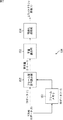
図5は、本技術の画像処理装置を適用した超音波画像処理装置の構成例を示す図である。
<Configuration example of ultrasonic image processing apparatus>
FIG. 5 is a diagram illustrating a configuration example of an ultrasonic image processing apparatus to which the image processing apparatus of the present technology is applied.
図5に示される超音波画像処理装置100は、超音波を用いて検査対象者(対象物)の内部の画像(すなわち、超音波画像)を撮影し、表示する装置である。超音波画像処理装置100は、例えば、医療用として患者の身体の内部や胎児などの撮影に用いられたり、手術中に臓器や組織に直接当てて用いられたり、工業用として製品の内部の断面などの撮影に用いられたりする。
An ultrasonic
特に、この超音波画像処理装置100は、被写体の超音波画像を撮影し、超音波を用いて組織の硬さを評価(検査)するエラストグラフィ画像(歪画像とも称する)を表示する。
In particular, the ultrasonic
超音波画像処理装置100は、図2のプローブ21および画像処理部111を含むように構成されている。
The ultrasonic
プローブ21は、被写体(生体;例えば、皮膚)などに押しつけて、被写体の画像を撮影する部位である。なお、プローブ21は、1.5Dアレイであってもよいし、2Dアレイであってもよい。
The
プローブ21は、超音波を出力するとともに、検査対象者(の体内)で超音波が反射されることにより戻ってくる反射波を受信する超音波プローブであり、超音波送受信部121を有する。
The
超音波送受信部121は、例えば、プローブ21の先端に設けられている。超音波送受信部121は、超音波を発生して出力するとともに、検査対象者で反射された超音波の反射波を受信し、その反射波の強度を表す反射波データ(RFデータ)を、画像処理部111の複素化部131に出力する。
The ultrasonic transmission /
画像処理部111は、複素化部131、X/Y方向成分分離部132、Bモード画像生成部133、歪画像生成部134、および画像重畳部135を含むように構成されている。
The
複素化部131には、プローブ21において受信されたN×M本のRFデータが入力される。ここで、Nは、X方向の素子数、MはY方向の素子数である。複素化部131は、実数のRFデータを複素数のIQデータに変換する。例えば、直交変換やヒルベルト変換が用いられる。複素化部131は、IQデータをX/Y方向成分分離部132に出力する。
N × M RF data received by the
X/Y方向成分分離部132は、複素化部131からのIQデータのペア(X方向IQデータとY方向IQデータ)を生成する。X方向IQデータは、X方向に並んだIQデータであり、例えば、M/2の位置のN本のIQデータ群である。Y方向IQデータは、Y方向に並んだIQデータであり、例えば、0乃至N-1の各位置におけるM本のIQデータ群である。
The X / Y direction
X方向IQデータは、Bモード画像生成に用いられる。Y方向IQデータは、動きを考慮した歪量を算出するために用いられる。X/Y方向成分分離部132は、X方向IQデータをBモード画像生成部133に出力し、Y方向IQデータを歪画像生成部134に出力する。
The X direction IQ data is used for B-mode image generation. The Y-direction IQ data is used for calculating a distortion amount considering the motion. The X / Y direction
Bモード画像生成部133は、X/Y方向成分分離部132からのX方向IQデータから、X方向B(Brightness)モード画像(輝度画像)を生成し、生成したX方向Bモード画像を、画像重畳部135に出力する。
The B mode
歪画像生成部134は、X/Y方向成分分離部132からのY方向IQデータを用いて、Z方向振動に伴う変位を検出し、変位量から歪量を算出し、その歪量を色情報に変換したY方向歪画像(エラストグラフィ画像)を、画像重畳部135に出力する。
The distortion
画像重畳部135は、Bモード画像生成部133からのX方向のBモード画像と、歪画像生成部134からのY方向のエラストグラフィ画像を重畳する。これにより、画像重畳部135からは、Bモード画像に重畳されたエラストグラフィ画像(歪画像)が出力され、図示せぬ後段の表示部などに表示される。
The
<Bモード画像生成部の構成>
図6は、Bモード画像生成部の構成例を示すブロック図である。
<Configuration of B-mode image generator>
FIG. 6 is a block diagram illustrating a configuration example of the B-mode image generation unit.
図6の例において、Bモード画像生成部133は、包絡線算出部141および対数変換部142を含むように構成されている。
In the example of FIG. 6, the B-mode
包絡線算出部141は、X方向IQデータを用いて、包絡線(絶対値)を算出する。対数変換部142は、包絡線算出部141により算出された包絡線に基づいて、対数変換を行い、包絡線の振幅を輝度に変換することで、X方向Bモード画像(輝度画像)を生成する。対数変換部142は、生成したX方向Bモード画像を、画像重畳部135に供給する。
The
<歪画像生成部の構成>
図7は、歪画像生成部の構成例を示すブロック図である。なお、歪画像生成部134における処理は、0乃至N-1の各位置におけるM本のIQデータ群のそれぞれに対して実行される。
<Configuration of distortion image generation unit>
FIG. 7 is a block diagram illustrating a configuration example of the distorted image generation unit. Note that the processing in the distorted
図7の例において、歪画像生成部134は、フレームメモリ151、フレーム間変位算出部152、歪量算出部153、および可視化処理部154を含むように構成されている。
In the example of FIG. 7, the distorted
フレームメモリ151およびフレーム間変位算出部152には、図5のX/Y方向成分分離部132からのY方向IQデータが入力される。
The Y direction IQ data from the X / Y direction
フレームメモリ151は、X/Y方向成分分離部132からのY方向IQデータ(異なる時刻(例えば、直前)のデータ)を蓄積する。
The
フレーム間変位算出部152は、X/Y方向成分分離部132からの時刻tのY方向IQデータ(以下、IQデータ(t)とも称する)と、フレームメモリ151からの時刻t-1のY方向IQデータ(以下、IQデータ(t-1)とも称する)とを用いて、Z方向振動に伴う変位を検出する。その際、Y方向に動くことにより発生するラインのずれが検出され、補正されて、Z方向振動に伴う変位が検出される。なお、時刻t-1のデータは、直前のデータを意味するが、これに限らず、異なる時刻のデータであればよい。フレーム間変位算出部152は、検出した変位の量を、歪量算出部153に供給する。
The inter-frame
歪量算出部153は、フレーム間変位算出部152からの変位量に基づいて歪量を算出する。例えば、歪量は、変位量を微分することで求められる。例えば、微分値の傾きが大きいと大きな歪みがあることを示し、傾きが小さいと歪みが小さいことを示す。歪量算出部153は、算出した歪量を可視化処理部154に供給する。
The distortion
可視化処理部154は、歪量をカラー情報に変換する。なお、歪みが大きいと、柔らかいということであり、歪みが小さいと硬いということである。例えば、歪量の画面内平均値をGreen、歪量の画面内平均よりも小さな値をBlue、歪量の画面内平均よりも大きな値をRedとして可視化される。可視化処理部154は、変換したカラー情報を、エラストグラフィ画像(Y方向歪画像)として、図5の画像重畳部135に出力する。
The
<フレーム間変位算出部の構成>
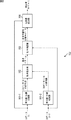
図8は、フレーム間変位算出部の構成例を示すブロック図である。
<Configuration of inter-frame displacement calculation unit>
FIG. 8 is a block diagram illustrating a configuration example of the inter-frame displacement calculation unit.
図8の例において、フレーム間変位算出部152は、絶対値/位相分離部161−1および161−2、動き検出部162、動き補償部163、および位相差検出部164を含むように構成される。
In the example of FIG. 8, the interframe
図6のX/Y方向成分分離部132からのY方向IQデータ(t)は、絶対値/位相分離部161−1および位相差検出部164に入力される。図7のフレームメモリ151からのY方向IQデータ(t-1)は、絶対値/位相分離部161−2および動き補償部163に入力される。
The Y direction IQ data (t) from the X / Y direction
絶対値/位相分離部161−1は、Y方向IQデータ(t)から絶対値と位相とを分離し、IQデータ(t)の絶対値を取得し、取得した絶対値を、動き検出部162に出力する。絶対値/位相分離部161−2は、Y方向IQデータ(t-1)から絶対値と位相とを分離し、IQデータ(t-1)の絶対値を取得し、取得した絶対値を、動き検出部162に出力する。
The absolute value / phase separation unit 161-1 separates the absolute value and the phase from the Y-direction IQ data (t), acquires the absolute value of the IQ data (t), and uses the acquired absolute value as the
動き検出部162は、IQデータの絶対値成分を用いて、時刻tと時刻t-1の間の動き量を検出する。例えば、動き量は、ブロックマッチングを用いて、動きベクトルとして検出される。なお、動き検出により位置合わせが行われる。すなわち、位置合わせができれば、動き検出に限定されず、また、動き検出方法もブロックマッチングに限定されない。動き検出部162は、検出された動きベクトルを、動き補償部163に出力する。
The
動き補償部163は、動き検出部162により検出された動きベクトルを用いて、時刻t-1のIQデータに対して補間処理を行い、動き補償後の複素データを生成する。この補間処理について図9を参照して説明する。
The
図9は、補間処理の例を示す図である。図9の例において、mとm+1は、隣接するIQデータである。移動量wが素子間ピッチ未満のとき、mとm+1の間のIQデータを補間処理によって作ることになる。例えば、移動量wを重み量とした線形補間を、複素数データに適用することで、補間データ(動き補償後の複素データ)を作ることができる。動き補償部163は、動き補償後の複素データを、位相差検出部164に出力する。
FIG. 9 is a diagram illustrating an example of interpolation processing. In the example of FIG. 9, m and m + 1 are adjacent IQ data. When the movement amount w is less than the inter-element pitch, IQ data between m and m + 1 is created by interpolation processing. For example, interpolation data (complex data after motion compensation) can be created by applying linear interpolation with the movement amount w as a weight amount to complex data. The
位相差検出部164は、時刻tのIQデータと、動き補償後の時刻t-1のIQデータの間の位相差を検出し、変位量を算出する。例えば、位相差検出の方法としては、自己相関法などが用いられる。位相差検出部164は、算出した変位量を、歪量算出部153に供給する。
The phase
<超音波画像生成処理>
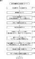
次に、図10のフローチャートを参照して、超音波画像処理装置100の超音波画像処理について説明する。
<Ultrasonic image generation processing>
Next, ultrasonic image processing of the ultrasonic
プローブ21の超音波送受信部121は、超音波を発生して出力するとともに、検査対象者で反射された超音波の反射波を受信し、その反射波の強度を表す反射波データ(RFデータ)を、画像処理部111の複素化部131に供給する。
The ultrasonic transmission /
ステップS111において、複素化部131は、2次元RFデータを取得する。
In step S111, the
ステップS112において、複素化部131は、取得したRFデータの複素化を行う。すなわち、複素化部131は、実数のRFデータを複素数のIQデータに変換し、変換されたIQデータを、X/Y方向成分分離部132に出力する。
In step S112, the
ステップS113において、X/Y方向成分分離部132は、X方向複素数データとY方向複素数データとに分離を行う。X/Y方向成分分離部132は、X方向IQデータをBモード画像生成部133に出力し、Y方向IQデータを歪画像生成部134に出力する。
In step S113, the X / Y direction
ステップS114において、Bモード画像生成部133は、X/Y方向成分分離部132からのX方向IQデータから、X方向Bモード画像(輝度画像)を生成する。すなわち、包絡線算出部141は、X方向IQデータを用いて、包絡線(絶対値)を算出する。対数変換部142は、包絡線算出部141により算出された包絡線に基づいて、対数変換を行い、包絡線の振幅を輝度に変換することで、X方向Bモード画像(輝度画像)を生成する。
Bモード画像生成部133(対数変換部142)は、生成したX方向Bモード画像を、画像重畳部135に出力する。
In step S <b> 114, the B mode
The B-mode image generation unit 133 (logarithmic conversion unit 142) outputs the generated X-direction B-mode image to the
歪画像生成部134において、図6のX/Y方向成分分離部132からのY方向IQデータ(t)は、絶対値/位相分離部161−1および位相差検出部164に入力される。図7のフレームメモリ151からのY方向IQデータ(t-1)は、絶対値/位相分離部161−2および動き補償部163に入力される。
In the distorted
ステップS115において、絶対値/位相分離部161−1および161−2は、Y方向IQデータの絶対値を取得する。すなわち、絶対値/位相分離部161−1は、Y方向IQデータ(t)から絶対値と位相とを分離し、IQデータ(t)の絶対値を取得し、取得した絶対値を、動き検出部162に出力する。絶対値/位相分離部161−2は、Y方向IQデータ(t-1)から絶対値と位相とを分離し、IQデータ(t-1)の絶対値を取得し、取得した絶対値を、動き検出部162に出力する。
In step S115, the absolute value / phase separators 161-1 and 161-2 acquire the absolute value of the Y direction IQ data. That is, the absolute value / phase separation unit 161-1 separates the absolute value and the phase from the Y-direction IQ data (t), acquires the absolute value of the IQ data (t), and uses the acquired absolute value as a motion detection. To the
ステップS116において、動き検出部162は、時刻tと時刻t-nのフレーム間で動き検出を行い、動きベクトルを求める。動き検出部162は、検出された動きベクトルを、動き補償部163に出力する。
In step S116, the
ステップS117において、動き補償部163は、動き検出部162により検出された動きベクトルを用いて、時刻t-nのフレームの動き補償を行う。すなわち、動き補償部163は、IQデータ(t-n)に対して補間処理を行い、動き補償後の複素データを生成する。動き補償部163は、動き補償後の複素データを、位相差検出部164に出力する。
In step S117, the
ステップS118において、位相差検出部164は、動き補償フレーム(動き補償後の時刻t-1のIQデータ)と、時刻tのIQデータとの間の位相差を検出し、変位量を算出する。位相差検出部164は、算出した変位量を、歪量算出部153に出力する。
In step S118, the phase
ステップS119において、歪量算出部153は、フレーム間変位算出部152からの変位量を歪量に変換する。例えば、歪量は、変位量を微分することで求められる。歪量算出部153は、変換により算出した歪量を可視化処理部154に供給する。
In step S119, the distortion
次に、可視化処理部154は、歪量をカラー情報に変換する。可視化処理部154は、変換したカラー情報を、エラストグラフィ画像(Y方向歪画像)として、図5の画像重畳部135に出力する。
Next, the
ステップS120において、画像重畳部135は、Bモード画像生成部133からのX方向のBモード画像と、歪画像生成部134からのY方向のエラストグラフィ画像を重畳する。これにより、画像重畳部135からは、Bモード画像に重畳されたエラストグラフィ画像(歪画像)が出力される。
In step S120, the
本技術においては、プローブが移動する場合に、プローブが移動する方向のフレーム間のずれ量を補正した後で、位相差を検出して歪み量を算出するようにした。 In the present technology, when the probe moves, the amount of distortion is calculated by detecting the phase difference after correcting the shift amount between frames in the direction in which the probe moves.
これにより、プローブが動いた状態で、正確な変位検出を行うことができる。したがって、組織の硬さを正しく求めることができる。 Thus, accurate displacement detection can be performed with the probe moving. Therefore, the hardness of the tissue can be obtained correctly.
また、プローブを動かしながら、組織の硬さを評価できるため、検査時間の短縮になり、術者(検査対象者)の負担軽減にもつながる。 Moreover, since the hardness of the tissue can be evaluated while moving the probe, the examination time is shortened and the burden on the operator (inspection subject) is reduced.
なお、プローブの動きとしては、図1を参照して上述したように、使用者の故意の操作による動きだけでなく、使用者の意図せぬ手振れなどの動きも含まれる。すなわち、手振れをしたとしても、正確な変位検出を行うことができる。 As described above with reference to FIG. 1, the movement of the probe includes not only a movement by a user's intentional operation but also a movement such as an unintended hand movement of the user. That is, accurate displacement detection can be performed even if the camera shakes.
さらに、上記説明においては、エラストグラフィ画像(歪画像)に、Bモード画像を合成して表示する例を説明したが、Bモード画像を合成することなしに表示させてもよい。また、合成する画像としては、Bモード画像だけに限らず、どんな画像であってもよい。具体的には、エラストグラフィ画像に、被写体に関する画像として、被写体のCT画像、被写体のMRI画像、被写体の内視鏡画像(内視鏡により撮影されたビデオ画像または静止画像)などを合成することも可能である。 Further, in the above description, an example in which a B-mode image is synthesized and displayed on an elastography image (distorted image) has been described, but the B-mode image may be displayed without being synthesized. Further, the image to be combined is not limited to the B mode image, and any image may be used. Specifically, combining an elastography image with a CT image of the subject, an MRI image of the subject, an endoscopic image of the subject (a video image or a still image taken by the endoscope), etc. Is also possible.
なお、本技術は、プローブを故意に動かす場合に限らず、手振れなどで動く場合などにも適用することができる。 Note that the present technology is not limited to a case where the probe is intentionally moved, but can also be applied to a case where the probe is moved by hand shake or the like.
また、本技術は、医療用途および非医療用途のいずれにも用いることが可能である。また、本技術は、人間だけでなく、例えば、動物や植物、人工物など、超音波により被写体の断面の撮影を行う様々な場面に用いることができる。 In addition, the present technology can be used for both medical applications and non-medical applications. Further, the present technology can be used not only for human beings but also for various scenes in which a cross section of a subject is photographed by ultrasonic waves such as animals, plants, and artificial objects.
上述した一連の処理は、ハードウエアにより実行することもできるし、ソフトウエアにより実行することもできる。一連の処理をソフトウエアにより実行する場合には、そのソフトウエアを構成するプログラムが、コンピュータにインストールされる。ここで、コンピュータには、専用のハードウエアに組み込まれているコンピュータや、各種のプログラムをインストールすることで、各種の機能を実行することが可能な汎用のパーソナルコンピュータなどが含まれる。 The series of processes described above can be executed by hardware or can be executed by software. When a series of processing is executed by software, a program constituting the software is installed in the computer. Here, the computer includes a computer incorporated in dedicated hardware, a general-purpose personal computer capable of executing various functions by installing various programs, and the like.
<第2の実施の形態>
[コンピュータの構成例]
図11は、上述した一連の処理をプログラムにより実行するコンピュータのハードウエアの構成例を示すブロック図である。
<Second Embodiment>
[Computer configuration example]
FIG. 11 is a block diagram illustrating a hardware configuration example of a computer that executes the above-described series of processing by a program.
コンピュータにおいて、CPU(Central Processing Unit)401、ROM(Read Only Memory)402、RAM(Random Access Memory)403は、バス404により相互に接続されている。
In a computer, a CPU (Central Processing Unit) 401, a ROM (Read Only Memory) 402, and a RAM (Random Access Memory) 403 are connected to each other via a
バス404には、さらに、入出力インタフェース405が接続されている。入出力インタフェース405には、入力部406、出力部407、記憶部408、通信部409、およびドライブ410が接続されている。
An input /
入力部406は、キーボード、マウス、マイクロホンなどよりなる。出力部407は、ディスプレイ、スピーカなどよりなる。記憶部408は、ハードディスクや不揮発性のメモリなどよりなる。通信部409は、ネットワークインタフェースなどよりなる。ドライブ410は、磁気ディスク、光ディスク、光磁気ディスク、又は半導体メモリなどのリムーバブル記録媒体411を駆動する。
The
以上のように構成されるコンピュータでは、CPU401が、例えば、記憶部408に記憶されているプログラムを入出力インタフェース405及びバス404を介してRAM403にロードして実行することにより、上述した一連の処理が行われる。
In the computer configured as described above, for example, the
コンピュータ(CPU401)が実行するプログラムは、例えば、パッケージメディア等としてのリムーバブル記録媒体411に記録して提供することができる。また、プログラムは、ローカルエリアネットワーク、インターネット、デジタル放送といった、有線または無線の伝送媒体を介して提供することができる。
The program executed by the computer (CPU 401) can be provided by being recorded on, for example, a
コンピュータでは、プログラムは、リムーバブル記録媒体411をドライブ410に装着することにより、入出力インタフェース405を介して、記憶部408にインストールすることができる。また、プログラムは、有線または無線の伝送媒体を介して、通信部409で受信し、記憶部408にインストールすることができる。その他、プログラムは、ROM402や記憶部408に、あらかじめインストールしておくことができる。
In the computer, the program can be installed in the
なお、コンピュータが実行するプログラムは、本明細書で説明する順序に沿って時系列に処理が行われるプログラムであっても良いし、並列に、あるいは呼び出しが行われたとき等の必要なタイミングで処理が行われるプログラムであっても良い。 The program executed by the computer may be a program that is processed in time series in the order described in this specification, or in parallel or at a necessary timing such as when a call is made. It may be a program for processing.
また、本明細書において、システムの用語は、複数の装置、ブロック、手段などにより構成される全体的な装置を意味するものである。 Further, in the present specification, the term “system” means an overall device configured by a plurality of devices, blocks, means, and the like.
なお、本開示における実施の形態は、上述した実施の形態に限定されるものではなく、本開示の要旨を逸脱しない範囲において種々の変更が可能である。 The embodiments in the present disclosure are not limited to the above-described embodiments, and various modifications can be made without departing from the gist of the present disclosure.
以上、添付図面を参照しながら本開示の好適な実施形態について詳細に説明したが、開示はかかる例に限定されない。本開示の属する技術の分野における通常の知識を有するであれば、特許請求の範囲に記載された技術的思想の範疇内において、各種の変更例また修正例に想到し得ることは明らかであり、これらについても、当然に本開示の技術的範囲に属するものと了解される。 The preferred embodiments of the present disclosure have been described in detail above with reference to the accompanying drawings, but the disclosure is not limited to such examples. It is clear that various changes and modifications can be conceived within the scope of the technical idea described in the claims if the person has ordinary knowledge in the technical field to which the present disclosure belongs, Of course, it is understood that these also belong to the technical scope of the present disclosure.
なお、本技術は以下のような構成も取ることができる。
(1) プローブが移動する場合に、第1のフレームと、前記第1のフレームとは異なる時刻のフレームである第2のフレームとの間のずれ量を補正するずれ量補正部と、
前記第1のフレームと前記ずれ量補正部によりずれ量が補正された第2フレームとから検出された位相差に基づいて歪量を算出する歪量算出部と
を備える画像処理装置。
(2) 前記歪量算出部により算出された歪量を、Bモード画像に重畳する重畳部を
さらに備える前記(1)に記載の画像処理装置。
(3) 前記第1のフレームおよび前記第2のフレームは、前記Bモード画像が生成される方向に平行な方向以外の方向の画像である
前記(2)に記載の画像処理装置。
(4) 前記第1のフレームおよび前記第2のフレームは、前記Bモード画像が生成される方向に平行な方向の画像である
前記(2)に記載の画像処理装置。
(5) 前記第1のフレームおよび前記第2のフレームは、前記プローブが移動する方向に平行な方向の画像である
前記(2)に記載の画像処理装置。
(6) 前記重畳部は、前記歪量算出部により算出された歪量を、前記歪量が算出された方向に直交する方向のBモード画像に重畳する
前記(2)に記載の画像処理装置。
(7) 前記重畳部は、前記歪量算出部により算出された歪量を、前記歪量が算出された方向に平行する方向のBモード画像に重畳する
前記(2)に記載の画像処理装置。
(8) 前記歪量算出部により算出された歪量を、被写体に関する内視鏡画像に重畳する重畳部を
さらに備える前記(2)に記載の画像処理装置。
(9) 画像処理装置が、
プローブが移動する場合に、第1のフレームと、前記第1のフレームとは異なる時刻のフレームである第2のフレームとの間のずれ量を補正し、
前記第1のフレームと前記ずれ量が補正された第2フレームとから検出された位相差に基づいて歪量を算出する
画像処理方法。
(10) プローブと、
画像処理部と
を備え、
前記画像処理部は、プローブが移動する場合に、第1のフレームと、前記第1のフレームとは異なる時刻のフレームである第2のフレームとの間のずれ量を補正するずれ量補正部と、
前記第1のフレームと前記ずれ量補正部によりずれ量が補正された第2フレームとから検出された位相差に基づいて歪量を算出する歪量算出部と
を備える超音波診断装置。
(11) 前記画像処理部は、前記歪量算出部により算出された歪量を、Bモード画像に重畳する重畳部を
さらに備える前記(10)に記載の超音波診断装置。
(12) 前記プローブは、第1の方向および第1の方向に直交する第2の方向に、それぞれ複数の圧電素子を有し、
前記第1のフレームおよび前記第2のフレームは、前記Bモード画像が生成される方向に平行な方向以外の方向の画像である
前記(11)に記載の超音波診断装置。
In addition, this technique can also take the following structures.
(1) When the probe moves, a shift amount correction unit that corrects a shift amount between the first frame and a second frame that is a frame at a time different from the first frame;
An image processing apparatus comprising: a distortion amount calculation unit that calculates a distortion amount based on a phase difference detected from the first frame and a second frame in which the shift amount is corrected by the shift amount correction unit.
(2) The image processing device according to (1), further including a superimposition unit that superimposes the distortion amount calculated by the distortion amount calculation unit on a B-mode image.
(3) The image processing device according to (2), wherein the first frame and the second frame are images in directions other than a direction parallel to a direction in which the B-mode image is generated.
(4) The image processing device according to (2), wherein the first frame and the second frame are images in a direction parallel to a direction in which the B-mode image is generated.
(5) The image processing device according to (2), wherein the first frame and the second frame are images in a direction parallel to a direction in which the probe moves.
(6) The image processing device according to (2), wherein the superimposing unit superimposes the distortion amount calculated by the distortion amount calculating unit on a B-mode image in a direction orthogonal to the direction in which the distortion amount is calculated. .
(7) The image processing device according to (2), wherein the superimposing unit superimposes the distortion amount calculated by the distortion amount calculating unit on a B-mode image in a direction parallel to the direction in which the distortion amount is calculated. .
(8) The image processing device according to (2), further including a superimposing unit that superimposes the distortion amount calculated by the distortion amount calculating unit on an endoscopic image related to the subject.
(9) The image processing apparatus is
When the probe moves, the amount of deviation between the first frame and the second frame, which is a frame at a time different from the first frame, is corrected,
An image processing method for calculating a distortion amount based on a phase difference detected from the first frame and a second frame in which the shift amount is corrected.
(10) a probe;
An image processing unit, and
The image processing unit includes a shift amount correction unit that corrects a shift amount between a first frame and a second frame that is a frame at a time different from the first frame when the probe moves. ,
An ultrasonic diagnostic apparatus comprising: a distortion amount calculation unit that calculates a distortion amount based on a phase difference detected from the first frame and a second frame whose deviation amount is corrected by the deviation amount correction unit.
(11) The ultrasonic diagnostic apparatus according to (10), wherein the image processing unit further includes a superimposition unit that superimposes the distortion amount calculated by the distortion amount calculation unit on a B-mode image.
(12) The probe includes a plurality of piezoelectric elements in each of a first direction and a second direction orthogonal to the first direction,
The ultrasonic diagnostic apparatus according to (11), wherein the first frame and the second frame are images in directions other than a direction parallel to a direction in which the B-mode image is generated.
21 プローブ, 31 圧電素子, 22 X方向超音波画像, 23 Y方向超音波画像, 100 超音波画像処理装置, 111 画像処理部, 121 超音波送受信部, 131 複素化部, 132 X/Y方向成分分離部, 133 Bモード画像生成部, 134 歪画像生成部, 135 画像重畳部, 141 包絡線算出部, 142 対数変換部, 151 フレームメモリ, 152 フレーム間変位算出部, 153 歪量算出部, 154 可視化処理部, 161−1,161−2 絶対値/位相分離部, 162 動き検出部, 163 動き補償部, 164 位相差検出部 21 probe, 31 piezoelectric element, 22 X direction ultrasonic image, 23 Y direction ultrasonic image, 100 ultrasonic image processing device, 111 image processing unit, 121 ultrasonic transmission / reception unit, 131 complexing unit, 132 X / Y direction component Separation unit, 133 B-mode image generation unit, 134 distortion image generation unit, 135 image superimposition unit, 141 envelope calculation unit, 142 logarithmic conversion unit, 151 frame memory, 152 interframe displacement calculation unit, 153 distortion amount calculation unit, 154 Visualization processing unit, 161-1 and 161-2 absolute value / phase separation unit, 162 motion detection unit, 163 motion compensation unit, 164 phase difference detection unit
Claims (12)
前記第1のフレームと前記ずれ量補正部によりずれ量が補正された第2フレームとから検出された位相差に基づいて歪量を算出する歪量算出部と
を備える画像処理装置。 A shift amount correction unit that corrects a shift amount between the first frame and a second frame that is a frame at a time different from the first frame when the probe moves;
An image processing apparatus comprising: a distortion amount calculation unit that calculates a distortion amount based on a phase difference detected from the first frame and a second frame in which the shift amount is corrected by the shift amount correction unit.
さらに備える請求項1に記載の画像処理装置。 The image processing apparatus according to claim 1, further comprising a superimposition unit that superimposes the distortion amount calculated by the distortion amount calculation unit on a B-mode image.
請求項2に記載の画像処理装置。 The image processing apparatus according to claim 2, wherein the first frame and the second frame are images in directions other than a direction parallel to a direction in which the B-mode image is generated.
請求項2に記載の画像処理装置。 The image processing apparatus according to claim 2, wherein the first frame and the second frame are images in a direction parallel to a direction in which the B-mode image is generated.
請求項2に記載の画像処理装置。 The image processing apparatus according to claim 2, wherein the first frame and the second frame are images in a direction parallel to a direction in which the probe moves.
請求項2の記載の画像処理装置。 The image processing apparatus according to claim 2, wherein the superimposing unit superimposes the distortion amount calculated by the distortion amount calculating unit on a B-mode image in a direction orthogonal to the direction in which the distortion amount is calculated.
請求項2の記載の画像処理装置。 The image processing apparatus according to claim 2, wherein the superimposing unit superimposes the distortion amount calculated by the distortion amount calculating unit on a B-mode image in a direction parallel to the direction in which the distortion amount is calculated.
さらに備える請求項1に記載の画像処理装置。 The image processing apparatus according to claim 1, further comprising a superimposition unit that superimposes the distortion amount calculated by the distortion amount calculation unit on an endoscopic image related to the subject.
プローブが移動する場合に、第1のフレームと、前記第1のフレームとは異なる時刻のフレームである第2のフレームとの間のずれ量を補正し、
前記第1のフレームと前記ずれ量が補正された第2フレームとから検出された位相差に基づいて歪量を算出する
画像処理方法。 The image processing device
When the probe moves, the amount of deviation between the first frame and the second frame, which is a frame at a time different from the first frame, is corrected,
An image processing method for calculating a distortion amount based on a phase difference detected from the first frame and a second frame in which the shift amount is corrected.
画像処理部と
を備え、
前記画像処理部は、プローブが移動する場合に、第1のフレームと、前記第1のフレームとは異なる時刻のフレームである第2のフレームとの間のずれ量を補正するずれ量補正部と、
前記第1のフレームと前記ずれ量補正部によりずれ量が補正された第2フレームとから検出された位相差に基づいて歪量を算出する歪量算出部と
を備える超音波診断装置。 A probe,
An image processing unit, and
The image processing unit includes a shift amount correction unit that corrects a shift amount between a first frame and a second frame that is a frame at a time different from the first frame when the probe moves. ,
An ultrasonic diagnostic apparatus comprising: a distortion amount calculation unit that calculates a distortion amount based on a phase difference detected from the first frame and a second frame whose deviation amount is corrected by the deviation amount correction unit.
さらに備える請求項10に記載の超音波診断装置。 The ultrasonic diagnostic apparatus according to claim 10, wherein the image processing unit further includes a superimposing unit that superimposes the distortion amount calculated by the distortion amount calculating unit on a B-mode image.
前記第1のフレームおよび前記第2のフレームは、前記Bモード画像が生成される方向に平行な方向以外の方向の画像である
請求項11に記載の超音波診断装置。 The probe has a plurality of piezoelectric elements in each of a first direction and a second direction orthogonal to the first direction;
The ultrasonic diagnostic apparatus according to claim 11, wherein the first frame and the second frame are images in directions other than a direction parallel to a direction in which the B-mode image is generated.
Priority Applications (2)
| Application Number | Priority Date | Filing Date | Title |
|---|---|---|---|
| JP2013244951A JP2015100613A (en) | 2013-11-27 | 2013-11-27 | Image processing apparatus and method, and ultrasonic diagnostic apparatus |
| US14/527,116 US9406126B2 (en) | 2013-11-27 | 2014-10-29 | Image processing apparatus and method, and ultrasonic diagnostic apparatus |
Applications Claiming Priority (1)
| Application Number | Priority Date | Filing Date | Title |
|---|---|---|---|
| JP2013244951A JP2015100613A (en) | 2013-11-27 | 2013-11-27 | Image processing apparatus and method, and ultrasonic diagnostic apparatus |
Publications (1)
| Publication Number | Publication Date |
|---|---|
| JP2015100613A true JP2015100613A (en) | 2015-06-04 |
Family
ID=53182710
Family Applications (1)
| Application Number | Title | Priority Date | Filing Date |
|---|---|---|---|
| JP2013244951A Pending JP2015100613A (en) | 2013-11-27 | 2013-11-27 | Image processing apparatus and method, and ultrasonic diagnostic apparatus |
Country Status (2)
| Country | Link |
|---|---|
| US (1) | US9406126B2 (en) |
| JP (1) | JP2015100613A (en) |
Cited By (2)
| Publication number | Priority date | Publication date | Assignee | Title |
|---|---|---|---|---|
| JP2023158119A (en) * | 2018-10-03 | 2023-10-26 | キヤノンメディカルシステムズ株式会社 | Analysis device and analysis program |
| US11995807B2 (en) | 2019-05-17 | 2024-05-28 | Supersonic Imagine | Method for ultrasound determination of a corrected image of a medium, and device for implementing this method |
Families Citing this family (3)
| Publication number | Priority date | Publication date | Assignee | Title |
|---|---|---|---|---|
| CN106558037B (en) * | 2016-11-18 | 2019-11-01 | 深圳开立生物医疗科技股份有限公司 | The antidote and system of ultrasound three-dimensional images |
| CN112154647B (en) * | 2018-04-26 | 2022-03-18 | 十以及二株式会社 | Wide-angle image delivery system |
| GB2610018B (en) * | 2021-06-04 | 2023-09-13 | Canon Kk | Information processing apparatus that notifies subject blur, image capturing apparatus, information processing method, and control method |
Family Cites Families (4)
| Publication number | Priority date | Publication date | Assignee | Title |
|---|---|---|---|---|
| EP1782736B1 (en) * | 2004-08-25 | 2012-06-06 | Hitachi Medical Corporation | Ultrasonographic device |
| US8057394B2 (en) * | 2007-06-30 | 2011-11-15 | St. Jude Medical, Atrial Fibrillation Division, Inc. | Ultrasound image processing to render three-dimensional images from two-dimensional images |
| US20100191113A1 (en) | 2009-01-28 | 2010-07-29 | General Electric Company | Systems and methods for ultrasound imaging with reduced thermal dose |
| US9289191B2 (en) * | 2011-10-12 | 2016-03-22 | Seno Medical Instruments, Inc. | System and method for acquiring optoacoustic data and producing parametric maps thereof |
-
2013
- 2013-11-27 JP JP2013244951A patent/JP2015100613A/en active Pending
-
2014
- 2014-10-29 US US14/527,116 patent/US9406126B2/en not_active Expired - Fee Related
Cited By (4)
| Publication number | Priority date | Publication date | Assignee | Title |
|---|---|---|---|---|
| JP2023158119A (en) * | 2018-10-03 | 2023-10-26 | キヤノンメディカルシステムズ株式会社 | Analysis device and analysis program |
| US12089989B2 (en) | 2018-10-03 | 2024-09-17 | Canon Medical Systems Corporation | Analyzing apparatus and analyzing method |
| JP7644186B2 (en) | 2018-10-03 | 2025-03-11 | キヤノンメディカルシステムズ株式会社 | Analysis device and program |
| US11995807B2 (en) | 2019-05-17 | 2024-05-28 | Supersonic Imagine | Method for ultrasound determination of a corrected image of a medium, and device for implementing this method |
Also Published As
| Publication number | Publication date |
|---|---|
| US9406126B2 (en) | 2016-08-02 |
| US20150146953A1 (en) | 2015-05-28 |
Similar Documents
| Publication | Publication Date | Title |
|---|---|---|
| JP5049773B2 (en) | Ultrasonic diagnostic device, ultrasonic image processing device, ultrasonic image processing program | |
| US9307958B2 (en) | Ultrasonic diagnostic apparatus and an ultrasonic image processing apparatus | |
| CN104994792B (en) | Ultrasonic diagnostic device and medical image processing device | |
| CN107647880B (en) | Medical image processing apparatus and medical image processing method | |
| JP7720456B2 (en) | Medical image diagnostic device, ultrasound diagnostic device, medical image system, and imaging control method | |
| CN102772225A (en) | Image processing device, image processing method, image processing system, and probe | |
| US9406126B2 (en) | Image processing apparatus and method, and ultrasonic diagnostic apparatus | |
| JP2010051729A (en) | Ultrasonic diagnostic device, ultrasonic image processing device and ultrasonic image processing program | |
| JP5559580B2 (en) | Ultrasound system and method for aligning 3D ultrasound images | |
| US20210128243A1 (en) | Augmented reality method for endoscope | |
| US10722217B2 (en) | Ultrasonic diagnostic apparatus and medical image processing apparatus | |
| JP6385702B2 (en) | Ultrasonic diagnostic apparatus, medical image processing apparatus, and medical image processing program | |
| WO2014064905A1 (en) | Method for creating three-dimensional ultrasonic image, and program | |
| JP6945334B2 (en) | Ultrasound diagnostic equipment and medical image processing equipment | |
| JP6207972B2 (en) | Ultrasonic diagnostic apparatus, image processing apparatus, and image processing program | |
| US20200077983A1 (en) | Ultrasonic diagnostic apparatus, medical image processing apparatus, and non-transitory computer medium storing computer program | |
| US20150164328A1 (en) | Ultrasound diagnostic apparatus | |
| JP2009011449A (en) | Ultrasonic diagnostic equipment | |
| JP4740695B2 (en) | Ultrasonic diagnostic equipment | |
| JP7233792B2 (en) | Diagnostic imaging device, diagnostic imaging method, program, and method for generating training data for machine learning | |
| US11730444B2 (en) | Image processing apparatus and ultrasound diagnosis apparatus | |
| TWM551477U (en) | An ultrasound diagnostic apparatus suitable for artificial intelligence imaging analysis | |
| JP6063154B2 (en) | Ultrasonic diagnostic equipment | |
| JP5072585B2 (en) | Ultrasonic diagnostic apparatus, ultrasonic image processing apparatus, and ultrasonic image processing program | |
| JP2020010747A (en) | Ultrasonic imaging method, ultrasonic imaging apparatus, ultrasonic imaging system, and ultrasonic imaging program |