JP2015097361A - Vibration piece, vibrator, oscillator, electronic device and mobile object - Google Patents
Vibration piece, vibrator, oscillator, electronic device and mobile object Download PDFInfo
- Publication number
- JP2015097361A JP2015097361A JP2013237473A JP2013237473A JP2015097361A JP 2015097361 A JP2015097361 A JP 2015097361A JP 2013237473 A JP2013237473 A JP 2013237473A JP 2013237473 A JP2013237473 A JP 2013237473A JP 2015097361 A JP2015097361 A JP 2015097361A
- Authority
- JP
- Japan
- Prior art keywords
- resonator element
- vibrating
- arms
- arm
- base
- Prior art date
- Legal status (The legal status is an assumption and is not a legal conclusion. Google has not performed a legal analysis and makes no representation as to the accuracy of the status listed.)
- Withdrawn
Links
Images


Landscapes
- Oscillators With Electromechanical Resonators (AREA)
- Piezo-Electric Or Mechanical Vibrators, Or Delay Or Filter Circuits (AREA)
Abstract
Description
本発明は、振動片、振動子、発振器、電子機器および移動体に関するものである。 The present invention relates to a resonator element, a vibrator, an oscillator, an electronic device, and a moving object.
水晶を用いた振動子(水晶振動子)は、周波数温度特性が優れていることから、種々の電子機器や移動体の基準周波数源や発信源等として広く用いられている。
このような振動子は、一般に、音叉型をなす振動片を備えている(例えば、特許文献1参照)。
例えば、特許文献1に記載の振動片は、1対の振動腕部と、これら振動腕部を繋ぐ基部と、基部から延びる保持腕部とを備えている。この振動片では、支持強度を十分に維持するとともに振動漏れを低減させる目的で、保持腕部の幅を振動腕部と同じかそれ以上にしている。
しかし、特許文献1に記載の振動片では、保持腕部の幅が振動腕部と同じかそれ以上であるため、外部から衝撃を受けた際、その衝撃が保持腕部を介して振動腕部に伝わりやすく、振動腕部の根元に応力が集中して振動腕部の損傷を招くという問題があった。
A crystal resonator (crystal resonator) is widely used as a reference frequency source, a transmission source, and the like for various electronic devices and moving objects because of excellent frequency temperature characteristics.
Such a vibrator generally includes a tuning fork-shaped vibrating piece (see, for example, Patent Document 1).
For example, the resonator element described in
However, in the resonator element described in
本発明の目的は、優れた耐衝撃性を有する振動片を提供すること、また、この振動片を備える信頼性に優れた振動子、発振器、電子機器および移動体を提供することにある。 An object of the present invention is to provide a resonator element having excellent impact resistance, and to provide a resonator, an oscillator, an electronic device, and a moving body that are excellent in reliability and include the resonator element.
本発明は、上述の課題の少なくとも一部を解決するためになされたものであり、以下の適用例として実現することが可能である。
[適用例1]
本発明の振動片は、基部と、
前記基部から第1方向に沿って延出され、前記第1方向に交差する第2方向に沿って並んでいる1対の振動腕と、
前記1対の振動腕を挟んで前記第2方向に沿って並んで配置されている1対の保持腕と、
前記基部と前記1対の保持腕とを接続している接続部と、
を含み、
前記保持腕には、対象物に取り付けられる固定部が配置され、
前記保持腕の前記固定部よりも前記接続部側の部分における最小幅をW1、
前記振動腕の最小幅をW2としたとき、
W1<W2
の関係を満たしていることを特徴とする。
このような振動片によれば、保持腕が振動腕よりも柔軟となるため、衝撃が加わった際に、その衝撃を保持腕で緩和し、衝撃を振動腕に伝わり難くして、振動腕の根元に応力が集中するのを低減し、その結果、振動腕の損傷を低減することができる。
SUMMARY An advantage of some aspects of the invention is to solve at least a part of the problems described above, and the invention can be implemented as the following application examples.
[Application Example 1]
The resonator element according to the invention includes a base,
A pair of vibrating arms extending along the first direction from the base and lined up along the second direction intersecting the first direction;
A pair of holding arms arranged side by side along the second direction across the pair of vibrating arms;
A connecting portion connecting the base and the pair of holding arms;
Including
The holding arm is provided with a fixing portion attached to the object,
W1 is the minimum width of the holding arm at a portion closer to the connecting portion than the fixed portion.
When the minimum width of the vibrating arm is W2,
W1 <W2
It is characterized by satisfying the relationship.
According to such a vibrating piece, since the holding arm is more flexible than the vibrating arm, when an impact is applied, the shock is mitigated by the holding arm, and the shock is hardly transmitted to the vibrating arm. It is possible to reduce stress concentration at the root, and as a result, it is possible to reduce damage to the vibrating arm.
[適用例2]
本発明の振動片では、前記接続部の最小幅をW3としたとき、
W1<W3
の関係を満たしていることが好ましい。
これにより、衝撃が加わった際に、接続部に応力が集中して接続部が損傷するのを低減することができる。
[Application Example 2]
In the resonator element according to the aspect of the invention, when the minimum width of the connection portion is W3,
W1 <W3
It is preferable that the relationship is satisfied.
Thereby, when an impact is added, it can reduce that a stress concentrates on a connection part and a connection part is damaged.
[適用例3]
本発明の振動片では、前記保持腕の前記固定部よりも前記接続部側の部分は、幅が一定であり、かつ、一方向に沿って延在していることが好ましい。
これにより、衝撃を受けた際に、保持腕の一部に応力が集中するのを低減することができる。
[適用例4]
本発明の振動片では、前記基部、前記振動腕、前記保持腕および前記接続部のそれぞれの厚さは、110μm以上であることが好ましい。
これにより、厚さ方向に衝撃が加わった際に、各部の耐衝撃性を高めることができる。
[Application Example 3]
In the resonator element according to the aspect of the invention, it is preferable that a portion of the holding arm closer to the connection portion than the fixed portion has a constant width and extends along one direction.
Thereby, it is possible to reduce the concentration of stress on a part of the holding arm when receiving an impact.
[Application Example 4]
In the resonator element according to the aspect of the invention, it is preferable that each thickness of the base portion, the vibrating arm, the holding arm, and the connecting portion is 110 μm or more.
Thereby, when an impact is applied in the thickness direction, the impact resistance of each part can be enhanced.
[適用例5]
本発明の振動片では、前記接続部は、平面視で前記基部の前記振動腕側とは反対側の端部に接続され、
前記保持腕は、前記接続部から前記振動腕側へ前記第1方向に沿って延出しており、
前記基部、前記振動腕、前記保持腕および前記接続部を含んで一体で形成されている構造体の前記第1方向に沿った長さをL1、
前記固定部と前記構造体の重心との間の前記第1方向に沿った長さをL2としたとき、
L2≦0.15×L1
の関係を満たしていることが好ましい。
これにより、固定部が構造体(振動片)の重心に対して近いため、振動片を対象物に対して固定部で固定する際に、振動片の姿勢を制御しやすくなる。
[Application Example 5]
In the resonator element according to the aspect of the invention, the connection portion is connected to an end portion of the base portion opposite to the vibrating arm side in a plan view,
The holding arm extends along the first direction from the connecting portion to the vibrating arm side,
The length along the first direction of the structure that is integrally formed including the base, the vibrating arm, the holding arm, and the connecting portion is L1,
When the length along the first direction between the fixed portion and the center of gravity of the structure is L2,
L2 ≦ 0.15 × L1
It is preferable that the relationship is satisfied.
Thereby, since the fixing portion is close to the center of gravity of the structure (vibrating piece), the posture of the vibrating piece can be easily controlled when the vibrating piece is fixed to the object by the fixing portion.
[適用例6]
本発明の振動片では、前記固定部は、前記重心に対して前記接続部側とは反対側を含んで配置されていることが好ましい。
これにより、振動片を対象物に対して固定部で固定する際に、振動片をその重心付近で保持しやすくなり、その結果、振動片の姿勢をより制御しやすくなる。
[Application Example 6]
In the resonator element according to the aspect of the invention, it is preferable that the fixed portion is disposed so as to include a side opposite to the connection portion side with respect to the center of gravity.
Accordingly, when the vibrating piece is fixed to the object by the fixing portion, the vibrating piece can be easily held near the center of gravity, and as a result, the posture of the vibrating piece can be more easily controlled.
[適用例7]
本発明の振動片では、前記固定部は、前記対象物に対して固定部材を介して取り付けられており、
前記固定部材のヤング率は、0.05GPa以上6.0GPa以下であることが好ましい。
これにより、外部から衝撃が加わった際に、その衝撃を固定部材で減衰させることができる。その結果、振動片の耐衝撃性を高めることができる。
[Application Example 7]
In the resonator element according to the aspect of the invention, the fixing portion is attached to the object via a fixing member.
The Young's modulus of the fixing member is preferably 0.05 GPa or more and 6.0 GPa or less.
Thereby, when an impact is applied from the outside, the impact can be attenuated by the fixing member. As a result, the impact resistance of the resonator element can be increased.
[適用例8]
本発明の振動子は、本発明の振動片と、
前記振動片が収納されているパッケージと、
を備えていることを特徴とする。
これにより、優れた信頼性を有する振動子を提供することができる。
[Application Example 8]
The vibrator of the present invention includes the resonator element of the present invention,
A package containing the vibrating piece;
It is characterized by having.
Thereby, a vibrator having excellent reliability can be provided.
[適用例9]
本発明の発振器は、本発明の振動片と、
前記振動片と電気的に接続されている回路と、
を備えていることを特徴とする。
これにより、優れた信頼性を有する発振器を提供することができる。
[Application Example 9]
The oscillator of the present invention includes the resonator element of the present invention,
A circuit electrically connected to the resonator element;
It is characterized by having.
Thereby, an oscillator having excellent reliability can be provided.
[適用例10]
本発明の電子機器は、本発明の振動片を備えていることを特徴とする。
これにより、優れた信頼性を有する電子機器を提供することができる。
[適用例11]
本発明の移動体は、本発明の振動片を備えていることを特徴とする。
これにより、優れた信頼性を有する移動体を提供することができる。
[Application Example 10]
An electronic apparatus according to the present invention includes the resonator element according to the present invention.
Thereby, an electronic device having excellent reliability can be provided.
[Application Example 11]
The moving body of the present invention includes the resonator element of the present invention.
Thereby, the mobile body which has the outstanding reliability can be provided.
以下、本発明の振動片、振動子、発振器、電子機器および移動体を図面に示す好適な実施形態に基づいて詳細に説明する。
1.振動子
まず、本発明の振動片を適用した振動子(本発明の振動子)について説明する。
図1は、本発明の実施形態に係る振動子の平面図、図2は、図1中のA−A線断面図、図3は、図1に示す振動子が有する振動片の断面図(図1中のB−B線断面図)である。また、図4は、振動腕の屈曲振動時の熱伝導について説明するための図、図5は、Q値とf/fmとの関係を示すグラフである。また、図6は、図1に示す振動子が有する振動片の平面図、図7は、図6中のC−C線断面図である。
Hereinafter, a resonator element, a vibrator, an oscillator, an electronic device, and a moving body of the present invention will be described in detail based on preferred embodiments shown in the drawings.
1. First, a vibrator to which the vibrator element of the invention is applied (a vibrator of the invention) will be described.
1 is a plan view of a vibrator according to an embodiment of the present invention, FIG. 2 is a cross-sectional view taken along line AA in FIG. 1, and FIG. 3 is a cross-sectional view of a resonator element included in the vibrator shown in FIG. It is a BB line sectional view in FIG. 4 is a diagram for explaining heat conduction during flexural vibration of the vibrating arm, and FIG. 5 is a graph showing the relationship between the Q value and f / fm. 6 is a plan view of the resonator element included in the vibrator shown in FIG. 1, and FIG. 7 is a cross-sectional view taken along the line CC in FIG.
なお、以下では、説明の便宜上、図1に示すように、互いに直交する3軸をX軸(電気軸)、Y軸(機械軸)およびZ軸(光学軸)とする。また、X軸に平行な方向(第2方向)を「X軸方向」、Y軸に平行な方向(第1方向)を「Y軸方向」、Z軸に平行な方向(第3方向)を「Z軸方向」という。また、各図において、これらの軸を図示した矢印の先端側を「+(プラス)」、基端側を「−(マイナス)」という。
図1および図2に示す振動子1は、振動片2(本発明の振動片)と、振動片2を収納するパッケージ9とを有している。以下、振動片2およびパッケージ9について、順次詳細に説明する。
In the following, for convenience of explanation, as shown in FIG. 1, the three axes orthogonal to each other are defined as an X axis (electric axis), a Y axis (mechanical axis), and a Z axis (optical axis). Also, the direction parallel to the X axis (second direction) is the “X axis direction”, the direction parallel to the Y axis (first direction) is the “Y axis direction”, and the direction parallel to the Z axis (third direction). It is called “Z-axis direction”. Moreover, in each figure, the front end side of the arrow which shows these axes is called "+ (plus)", and the base end side is called "-(minus)".
A
(振動片2)
図1、図2および図3に示すように、本実施形態の振動片2は、水晶基板3と、水晶基板3上に形成された第1駆動用電極84および第2駆動用電極85とを有している。なお、図1および図2では、説明の便宜上、第1駆動用電極84および第2駆動用電極85の図示を省略している。
(Vibration piece 2)
As shown in FIGS. 1, 2, and 3, the
水晶基板3は、Zカット水晶板で構成されている。これにより、振動片2は、優れた振動特性を発揮することができる。Zカット水晶板とは、水晶のZ軸(光学軸)を厚さ方向とする水晶基板である。なお、水晶のZ軸は、水晶基板3の厚さ方向と一致しているのが好ましいが、常温近傍における周波数温度変化を小さくする観点からは、厚さ方向に対して若干(例えば、15°未満程度)傾けることになる。
The
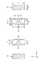
図1に示すように、水晶基板3は、基部4と、基部4から延出する1対の振動腕5、6と、基部4から延出する支持部7とを有している。
基部4は、X軸およびY軸に平行な平面であるXY平面に沿って広がり、Z軸方向を厚さ方向とする板状をなしている。また、支持部7は、基部4から−Y軸方向に延出する連結部71と、連結部71から+X軸方向および−X軸方向に分岐して延出する連結腕72、73と、連結腕72、73の先端部から+Y軸方向に延出する保持腕74、75とを有している。ここで、保持腕74、75は、1対の振動腕5、6を挟んでX軸方向に沿って並んで配置されている。また、連結部71および連結腕72、73は、基部4と保持腕74、75とを接続している「接続部」を構成している。
As shown in FIG. 1, the
The base 4 extends along the XY plane, which is a plane parallel to the X axis and the Y axis, and has a plate shape with the Z axis direction as the thickness direction. Further, the
振動腕5、6は、X軸方向に並び、かつ、互いに平行となるように、それぞれ、基部4から+Y軸方向に延出している。これら振動腕5、6は、それぞれ、長手形状をなし、基部4側の基端が固定端となり、基端から+Y軸方向にある先端が自由端となる。また、振動腕5、6の先端部には、錘部としてのハンマーヘッド59、69が設けられている。なお、ハンマーヘッド59、69には、周波数調整用の金属層が設けられていてもよい。
The vibrating
図3に示すように、振動腕5は、XY平面で構成された互いに表裏の関係にある一対の主面51、52と、YZ平面で構成され、一対の主面51、52を接続する一対の側面53、54とを有している。また、振動腕5は、主面51に開口する有底の溝55と、主面52に開口する有底の溝56とを有している。溝55、56は、それぞれ、Y軸方向に延在している。このような振動腕5は、溝55、56が形成されている部分では、略H型の横断面形状をなしている。
As shown in FIG. 3, the resonating
溝55、56は、図3に示すように、横断面において、振動腕5の厚みを二等分する線分Lに対して対称的に形成されているのが好ましく、さらに振動腕5の断面重心が振動腕5の形状中心と一致するように形成されているのが好ましい。これにより、振動腕5の不要な振動(具体的には、面外方向成分を有する斜め振動や捩り振動)を抑制でき、振動腕5を効率的に水晶基板3の面内方向に振動させることができる。
As shown in FIG. 3, the
振動腕5と同様に、振動腕6は、XY平面で構成された互いに表裏の関係にある一対の主面61、62と、YZ平面で構成され、一対の主面61、62を接続する一対の側面63、64とを有している。また、振動腕6は、主面61に開口する有底の溝65と、主面62に開口する有底の溝66とを有している。溝65、66は、それぞれ、Y軸方向に延在している。このような振動腕6は、溝65、66が形成されている部分では、略H型の横断面形状をなしている。
Similar to the vibrating
溝65、66は、図3に示すように、横断面において、振動腕6の厚みを二等分する線分Lに対して対称的に形成されているのが好ましく、更に振動腕5の断面重心が振動腕5の形状中心と一致するように形成されているのが好ましい。これにより、振動腕6の不要な振動を抑制でき、振動腕6を効率的に水晶基板3の面内方向に振動させることができる。
As shown in FIG. 3, the
振動腕5には、1対の第1駆動用電極84と1対の第2駆動用電極85とが形成されている。具体的には、一方の第1駆動用電極84は、溝55の内面に形成されており、他方の第1駆動用電極84は、溝56の内面に形成されている。また、一方の第2駆動用電極85は、側面53に形成されており、他方の第2駆動用電極85は、側面54に形成されている。なお図3は模式図であり、ウェットエッチングにより溝55、56、65、66を形成した場合では、水晶基板3など、基板の材料によってはエッチング速度の異方性により、例えば後述する図7に示すように図3の形状とは異なった略H型の横断面形状になる。
A pair of
同様に、振動腕6にも、1対の第1駆動用電極84と1対の第2駆動用電極85とが形成されている。具体的には、一方の第1駆動用電極84は、側面63に形成されており、他方の第1駆動用電極84は、側面64に形成されている。また、一方の第2駆動用電極85は、溝65の内面に形成されており、他方の第2駆動用電極85は、溝66の内面に形成されている。
このような第1駆動用電極84と第2駆動用電極85との間に交番電圧を印加すると、振動腕5、6が互いに接近、離間を繰り返すように面内方向(XY平面方向)に所定の周波数で振動する。
Similarly, a pair of
When an alternating voltage is applied between the
第1駆動用電極84および第2駆動用電極85の構成材料としては、それぞれ、特に限定されないが、例えば、金(Au)、金合金、白金(Pt)、アルミニウム(Al)、アルミニウム合金、銀(Ag)、銀合金、クロム(Cr)、クロム合金、銅(Cu)、モリブデン(Mo)、ニオブ(Nb)、タングステン(W)、鉄(Fe)、チタン(Ti)、コバルト(Co)、亜鉛(Zn)、ジルコニウム(Zr)等の金属材料、酸化インジウムスズ(ITO)等の導電材料により形成することができる。
以上、振動片2について簡単にその構成を説明した。上述したように、振動片2の各振動腕5、6に溝55、56、65、68を形成することによって、熱弾性損失の低減を図ることができ、優れた振動特性を発揮することができる。以下、この点について、詳述する。
The constituent materials of the
The configuration of the
振動腕5は、前述したように、第1駆動用電極84と第2駆動用電極との間に交番電圧を印加することにより面内方向に屈曲振動する。図4に示すように、この屈曲振動の際、振動腕5の側面53が収縮すると側面54が伸張し、反対に、側面53が伸張すると側面54が収縮する。振動腕5がGough−Joule効果を発生しない(エネルギー弾性がエントロピー弾性に対して支配的な)場合、側面53、54のうち、収縮する面側の温度は上昇し、伸張する面側の温度は下降するため、側面53と側面54との間、つまり振動腕5の内部に温度差が発生する。このような温度差に起因して側面53と側面54との間に熱伝導が生じると、振動エネルギーの損失が発生し、これにより振動片2のQ値が低下する。このようなQ値の低下を熱弾性効果とも言い、熱弾性効果によるエネルギーの損失を熱弾性損失とも言う。
As described above, the vibrating
振動片2のような構成の屈曲振動モードで振動する振動片において、振動腕5の屈曲振動周波数(機械的屈曲振動周波数)fが変化したとき、振動腕5の屈曲振動周波数が熱緩和周波数fmと一致するときにQ値が最小となる。この熱緩和周波数fmは、fm=1/(2πτ)で求めることができる(ただし、式中πは円周率であり、eをネイピア数とすれば、τは温度差が熱伝導によりe−1倍になるのに要する緩和時間である)。
また、平板構造の熱緩和周波数をfm0とすれば、fm0は下式で求めることができる。
fm0=πk/(2ρCpa2)‥‥(1)
In the vibration piece that vibrates in the bending vibration mode configured as the
Further, if the thermal relaxation frequency of the flat plate structure is fm0, fm0 can be obtained by the following equation.
fm0 = πk / (2ρCpa 2 ) (1)
なお、πは円周率、kは振動腕5の振動方向の熱伝導率、ρは振動腕5の質量密度、Cpは振動腕5の熱容量、aは振動腕5の振動方向の幅である。式(1)の熱伝導率k、質量密度ρ、熱容量Cpに振動腕5の材料そのもの(すなわち水晶)の定数を入力した場合、求まる熱緩和周波数fm0は、振動腕5に溝55、56を設けていない場合の値となる。
Here, π is the circumference ratio, k is the thermal conductivity of the vibrating
図4に示すように、振動腕5では、側面53、54の間に位置するように溝55、56が形成されている。そのため、振動腕5の屈曲振動時に生じる側面53、54の温度差を熱伝導により温度平衡させるための熱移動経路が溝55と溝56との間(溝55、56の底部)を迂回するように形成され、熱移動経路が側面53、54間の直線距離(最短距離)よりも長くなる。そのため、振動腕5に溝55、56を設けていない場合と比較して緩和時間τが長くなり、熱緩和周波数fmが低くなる。
As shown in FIG. 4, in the vibrating
図5は、屈曲振動モードの振動片のQ値のf/fm依存性を表すグラフである。同図において、点線で示されている曲線F1は、振動片2のように振動腕に溝が形成されている場合(振動腕の横断面形状がH型の場合)を示し、実線で示されている曲線F2は、振動腕に溝が形成されていない場合(振動腕の横断面形状が矩形の場合)を示している。
図5に示すように、曲線F1、F2の形状は変わらないが、前述のような熱緩和周波数fmの低下に伴って、曲線F1が曲線F2に対して周波数低下方向へシフトする。したがって、振動片2のように振動腕に溝が形成されている場合の熱緩和周波数をfm1とすれば、f>√(fm0×fm1)の関係を満たせば、常に、振動腕に溝が形成されている振動片のQ値が振動腕に溝が形成されていない振動片のQ値に対して高くなる。
更に、f/fm0>1の関係に限定すれば、より高いQ値を得る事ができる。
FIG. 5 is a graph showing the f / fm dependency of the Q value of the vibration piece in the bending vibration mode. In the figure, a curved line F1 indicated by a dotted line indicates a case where a groove is formed in the vibrating arm like the vibrating piece 2 (when the cross-sectional shape of the vibrating arm is H-shaped), and is indicated by a solid line. A curved line F <b> 2 indicates a case where a groove is not formed in the vibrating arm (when the cross-sectional shape of the vibrating arm is rectangular).
As shown in FIG. 5, the shapes of the curves F1 and F2 are not changed, but the curve F1 shifts in the frequency lowering direction with respect to the curve F2 as the thermal relaxation frequency fm is reduced as described above. Therefore, if the thermal relaxation frequency when the groove is formed in the vibrating arm as in the vibrating
Furthermore, if the relationship is limited to f / fm0> 1, a higher Q value can be obtained.
なお、図5において、f/fm<1の領域を等温的領域とも言い、この等温的領域ではf/fmが小さくなるにつれてQ値が高くなる。これは、振動腕の機械的周波数が低くなる(振動腕の振動が遅くなる)につれて前述のような振動腕内の温度差が生じ難くなるためである。従って、f/fmを0に限りなく近づけた際の極限では、等温準静操作となって、熱弾性損失は限りなく零に接近する。一方、f/fm>1の領域を断熱的領域とも言い、この断熱的領域ではf/fmが大きくなるにつれてQ値が高くなる。これは、振動腕の機械的周波数が高くなるにつれて、各側面の温度上昇・温度低下の切り替わりが高速となり、前述のような熱伝導が生じる時間がなくなるためである。従って、f/fmを限りなく大きくした際の極限では、断熱操作となって、熱弾性損失は限りなく零に接近する。このことから、f/fm>1の関係を満たすとは、f/fmが断熱的領域にあるとも言い換えることができる。
以上、熱弾性損失について説明した。
In FIG. 5, a region where f / fm <1 is also referred to as an isothermal region. In this isothermal region, the Q value increases as f / fm decreases. This is because the temperature difference in the vibrating arm as described above is less likely to occur as the mechanical frequency of the vibrating arm becomes lower (the vibration of the vibrating arm becomes slower). Therefore, in the limit when f / fm is brought close to 0 as much as possible, the operation becomes an isothermal quasi-static operation, and the thermoelastic loss approaches zero as much as possible. On the other hand, a region where f / fm> 1 is also referred to as an adiabatic region. In this adiabatic region, the Q value increases as f / fm increases. This is because, as the mechanical frequency of the vibrating arm increases, the temperature increase / decrease switching on each side surface becomes faster, and there is no time for heat conduction as described above. Therefore, at the limit when f / fm is increased as much as possible, the operation becomes adiabatic, and the thermoelastic loss approaches zero as much as possible. From this, satisfying the relationship of f / fm> 1 can be rephrased as f / fm being in the adiabatic region.
The thermoelastic loss has been described above.
本実施形態では、前述したように、振動腕5、6がハンマーヘッド59、69を有している。このハンマーヘッド59、69は、振動腕5、6のハンマーヘッド59、69と基部4との間の部分である腕部50、60よりも幅が大きい。
また、本実施形態では、振動腕5、6の最小幅W2(腕部50、60の幅)は、水晶基板3の厚さTよりも小さい。これにより、厚さ方向(Z軸方向)に衝撃が加わった際に、振動腕5、6の耐衝撃性を高めることができる。また、溝55、56、65、66を深くして、励振効率を高めることもできる。具体的には、厚さ方向への小型化(薄型化)の観点を加えて、T/W2が、1.5以上2.4以下の範囲内にあることが好ましく、1.8以上2.2以下の範囲内にあることがより好ましく、1.9以上2.0以下の範囲内にあることがさらに好ましい。
In the present embodiment, as described above, the vibrating
In the present embodiment, the minimum width W2 of the vibrating
このような振動腕5、6が延出している基部4は、前述したように、連結部71および連結腕72、73を介して保持腕74、75が接続されており、図1および図2に示すように、この保持腕74、75がパッケージ9に固定される。なお、本実施形態では、保持腕74、75のそれぞれを1箇所でパッケージ9に対して固定しているが、保持腕74、75のそれぞれを2箇所以上でパッケージ9に対して固定してもよい。
As described above, the base 4 from which the vibrating
このような振動片2では、外部から衝撃(特にX軸方向の衝撃)を受けた際、その衝撃が連結部71、連結腕72、73および保持腕74、75を介して基部4に伝わり、振動腕5、6が屈曲すると、振動腕5、6の根元部分に応力が集中する。かかる応力が大きすぎると、振動腕5、6の損傷を招いてしまう。
そこで、振動片2は、かかる応力を低減するように各部の寸法が設定されている。以下、図6および図7に基づいて、この点を詳述する。
In such a vibrating
Therefore, the size of each part of the
保持腕74、75には、対象物であるパッケージ9に取り付けられる固定部741、742が設けられている。
そして、保持腕74、75の固定部741、751よりも接続部(連結部71および連結腕72、73)側の部分における最小幅をW1とし、振動腕5、6の最小幅をW2としたとき、W1<W2の関係を満たす。
The holding
The minimum width of the holding
このようなW1<W2の関係を満たすことにより、保持腕74、75が振動腕5、6よりも柔軟となるため、外部から衝撃が加わった際に、その衝撃を保持腕74、75で緩和し、衝撃を振動腕5、6に伝わり難くして、振動腕5、6の根元に応力が集中するのを低減することができる。その結果、振動腕5、6の損傷を低減することができる。これにより、振動片2が優れた耐衝撃性を発揮することができる。即ち、振動腕5や振動腕6が大きく損傷してしまった場合、屈曲振動の際に、損傷した部分に発生する歪みに基づく温度上昇(あるいは温度低下)が局所的に発生し、それが原因となって熱流が増大して熱弾性損失が大きくなる。従って、Q値が劣化すると共にCI値が大きくなり、振動片2を発振器に搭載して使用する場合には、発振余裕度が足りずに発振が停止してしまう虞がある。これに対して、保持腕74、75が損傷を受けた場合には、電気的な接続が確保されている限り、発振停止となる虞はない。
By satisfying such a relationship of W1 <W2, the holding
また、W1およびW2は、前述した関係を満たしていればよいが、W1/W2が、0.5以上0.9以下であることが好ましく、0.6以上0.8以下であることがより好ましく、0.7以上0.8以下であることがさらに好ましい。これにより、保持腕74、75の機械的強度と前述したような衝撃緩和効果とのバランスを優れたものとすることができる。
W1 and W2 may satisfy the above-described relationship, but W1 / W2 is preferably 0.5 or more and 0.9 or less, and more preferably 0.6 or more and 0.8 or less. Preferably, it is 0.7 or more and 0.8 or less. Thereby, the balance between the mechanical strength of the holding
ここで、振動片2に対して外部から衝撃が加わったとき、固定部741、751を起点として屈曲するように保持腕74、75が変形することとなる。このように変形する部分が仮に屈曲または湾曲したり幅が異なったりする部分を有していると、その部分に応力が集中し、保持腕74、75が損傷するおそれがある。そこで、本実施形態では、保持腕74、75は、幅が一定であり、かつ、一方向(具体的にはY軸方向)に沿って延在している。したがって、保持腕74、75の固定部741、751よりも接続部(連結部71および連結腕72、73)側の部分においても、幅が一定であり、かつ、一方向に沿って延在している。これにより、衝撃を受けた際に、前述したように保持腕74、75の一部に応力が集中するのを低減することができる。
なお、固定部741、751およびそれよりも先端側の部分については、屈曲または湾曲したり幅が異なったりする部分を有していてもよい。
Here, when an impact is applied to the
Note that the fixing
また、本実施形態では、連結部71および連結腕72、73の最小幅をW3としたとき、W1<W3の関係を満たす。これにより、連結部71および連結腕72、73の剛性が高められるため、外部から衝撃が加わった際に、連結部71および連結腕72、73に応力が集中して連結部71および連結腕72、73が損傷するのを低減することができる。
このような観点から、W1およびW3は、W1/W3が、0.5以上0.9以下であることが好ましく、0.6以上0.8以下であることがより好ましく、0.7以上0.8以下であることがさらに好ましい。
In this embodiment, when the minimum width of the connecting
From this viewpoint, W1 / W3 is preferably 0.5 or more and 0.9 or less, more preferably 0.6 or more and 0.8 or less, and more preferably 0.7 or more and 0 or less. More preferably, it is 8 or less.
また、水晶基板3の厚さTと保持腕74、75の最小幅W1との関係について、T/W1が、2.0以上3.0以下の範囲内にあることが好ましく、2.2以上2.8以下の範囲内にあることがより好ましく、2.4以上2.7以下の範囲内にあることがさらに好ましい。これにより、保持腕74、75全体の必要な機械的強度を確保しつつ、前述したような保持腕74、75の衝撃を緩和する効果を優れたものとすることができる。
また、水晶基板3の厚さTと連結部71および連結腕72、73の最小幅W3との関係について、T/W3が、1.0以上2.0以下の範囲内にあることが好ましい。これにより、連結部71および連結腕72、73全体の必要な機械的強度を確保しつつ、基部4からの振動漏れを低減することができる。
Further, regarding the relationship between the thickness T of the
Further, regarding the relationship between the thickness T of the
また、基部4、振動腕5、6、保持腕74、75および接続部(連結部71および連結腕72、73)の各部間は、角部を無くすようにテーパーが形成されているため、これらの部分間に応力が集中するのも低減することができる。
また、基部4、振動腕5、6、保持腕74、75および接続部(連結部71および連結腕72、73)のそれぞれの厚さ、すなわち、水晶基板3の厚さTは、110μm以上であることが好ましく、114μm以上120μm以下であることがより好ましい。これにより、振動片2の薄型化を維持しつつ、厚さ方向(Z軸方向)に衝撃が加わった際に、各部の耐衝撃性を高めることができる。なお、本実施形態では、水晶基板3の厚さが一定であり、基部4、振動腕5、6、保持腕74、75および接続部(連結部71および連結腕72、73)の厚さは、互いに等しいが、これらの厚さは、必要に応じて、互いに異なっていてもよい。
Further, since the base 4, the vibrating
The thickness of each of the base 4, the vibrating
また、前述したように、接続部(連結部71および連結腕72、73)は、基部4の振動腕5、6側とは反対側の端部に接続され、保持腕74、75は、接続部から振動腕5、6側へY軸方向に沿って延出している。そして、基部4、振動腕5、6、保持腕74、75および接続部を含んで一体で形成されている構造体のY軸方向に沿った長さ、すなわち、水晶基板3または振動片2のY軸方向に沿った長さをL1とし、固定部741、751と水晶基板3の重心Gとの間のY軸方向に沿った距離をL2としたとき、L2≦0.15×L1の関係を満たす。これにより、固定部741、751が水晶基板3または振動片2の重心Gに対して近いため、振動片2をパッケージ9に対して固定部741、751で固定する際に、振動片2の姿勢を制御しやすくなる。また、このような観点から、より好ましくは、L2≦0.05×L1の関係を満たすことが好ましい。
特に、固定部741、751は、水晶基板3または振動片2の重心Gに対して接続部(連結部71および連結腕72、73)側とは反対側に位置している。これにより、振動片2をパッケージ9に対して固定部741、751で固定する際に、振動片2をその重心G付近で保持しやすくなり、その結果、振動片2の姿勢をより制御しやすくなる。
As described above, the connecting portion (the connecting
In particular, the fixing
(パッケージ)
パッケージ9は、上面に開放する凹部911を有する箱状のベース91と、凹部911の開口を塞ぐようにベース91に接合されている板状のリッド92とを有している。このようなパッケージ9は、凹部911がリッド92にて塞がれることにより形成された収納空間を有しており、この収納空間に振動片2が気密的に収納されている。振動片2は、保持腕74、75の先端部(固定部741、751)にて、例えば、エポキシ系、アクリル系の樹脂に導電性フィラーを混合した導電性接着剤11を介して凹部911の底面に固定されている。
なお、収納空間内は、減圧(好ましくは真空)状態となっていてもよいし、窒素、ヘリウム、アルゴン等の不活性ガスが封入されていてもよい。これにより、振動片2の振動特性が向上する。
(package)
The
Note that the storage space may be in a reduced pressure (preferably vacuum) state, or may be filled with an inert gas such as nitrogen, helium, or argon. Thereby, the vibration characteristics of the
ベース91の構成材料としては、特に限定されないが、酸化アルミニウム等の各種セラミックスを用いることができる。また、リッド92の構成材料としては、特に限定されないが、ベース91の構成材料と線膨張係数が近似する部材であると良い。例えば、ベース91の構成材料を前述のようなセラミックスとした場合には、コバール等の合金とするのが好ましい。なお、ベース91とリッド92の接合は、特に限定されず、例えば、接着剤を介して接合してもよいし、シーム溶接等により接合してもよい。
The constituent material of the
また、ベース91の凹部911の底面には、接続端子951、961が形成されている。図示しないが、振動片2の第1駆動用電極84は、保持腕74の先端部(固定部741)まで引き出されており、当該部分にて、導電性接着剤11(固定部材)を介して接続端子951と電気的に接続されている。同様に、図示しないが、振動片2の第2駆動用電極85は、保持腕75の先端部(固定部751)まで引き出されており、当該部分にて、導電性接着剤11(固定部材)を介して接続端子961と電気的に接続されている。
In addition,
導電性接着剤11のヤング率は、0.05GPa以上6.0GPa以下の範囲内にあることが好ましく、0.05GPa以上3.0GPa以下の範囲内にあることがより好ましい。これにより、外部から衝撃が加わった際に、その衝撃を導電性接着剤11で減衰させることができる。その結果、振動片2の耐衝撃性を高めることができる。
このような導電性接着剤11としては、特に限定されず、例えば、エポキシ樹脂、アクリル樹脂等の樹脂材料中に金属粒子等の導電性フィラーを分散させた接着剤を用いることができる。
The Young's modulus of the
The
また、接続端子951は、ベース91を貫通する貫通電極952を介してベース91の底面に形成された外部端子953に電気的に接続されており、接続端子961は、ベース91を貫通する貫通電極962を介してベース91の底面に形成された外部端子963に電気的に接続されている。
接続端子951、961、貫通電極952、962および外部端子953、963の構成としては、それぞれ、導電性を有していれば、特に限定されないが、例えば、Cr(クロム)、W(タングステン)などのメタライズ層(下地層)に、Ni(ニッケル)、Au(金)、Ag(銀)、Cu(銅)などの各被膜を積層した金属被膜で構成することができる。
以上説明したような振動子1によれば、耐衝撃性に優れる振動片2を備えているため、優れた信頼性を発揮することができる。
The
The structures of the
According to the
2.発振器
次いで、本発明の振動片を適用した発振器(本発明の発振器)について説明する。
図8は、本発明の発振器の一例を示す断面図である。
図8に示す発振器10は、振動子1と、振動片2を駆動するためのICチップ(チップ部品)80とを有している。以下、発振器10について、前述した振動子との相違点を中心に説明し、同様の事項については、その説明を省略する。
2. Oscillator Next, an oscillator to which the resonator element according to the invention is applied (the oscillator according to the invention) will be described.
FIG. 8 is a cross-sectional view showing an example of the oscillator of the present invention.
An
パッケージ9は、凹部911を有する箱状のベース91と、凹部911の開口を塞ぐ板状のリッド92とを有している。
ベース91の凹部911は、ベース91の上面に開口する第1凹部911aと、第1凹部911aの底面の中央部に開放する第2凹部911bと、第2凹部911bの底面の中央部に開口する第3凹部911cとを有している。
The
The
第1凹部911aの底面には、接続端子95、96が形成されている。また、第3凹部911cの底面には、ICチップ80が配置されている。ICチップ80は、振動片2の駆動を制御するための駆動回路(発振回路)を有している。ICチップ80によって振動片2を駆動すると、所定の周波数の信号を取り出すことができる。
また、第2凹部911bの底面には、ワイヤーを介してICチップ80と電気的に接続された複数の内部端子93が形成されている。これら複数の内部端子93には、ベース91に形成された図示しないビアを介してパッケージ9の底面に形成された外部端子(実装端子)94に電気的に接続された端子と、図示しないビアやワイヤーを介して接続端子95に電気的に接続された端子と、図示しないビアやワイヤーを介して接続端子96に電気的に接続された端子とが含まれている。
In addition, a plurality of
なお、図8に示す構成では、ICチップ80が収納空間内に配置されているが、ICチップ80の配置は、特に限定されず、例えば、パッケージ9の外側(ベースの底面)に配置されていてもよい。
このような発振器10によれば、前述したような耐衝撃性に優れる振動片2を備えるため、信頼性に優れる。
In the configuration shown in FIG. 8, the
According to such an
3.電子機器
次いで、本発明の振動片を適用した電子機器(本発明の電子機器)について、図9〜図11に基づき、詳細に説明する。
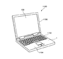
図9は、本発明の振動片を備える電子機器を適用したモバイル型(またはノート型)のパーソナルコンピューターの構成を示す斜視図である。この図において、パーソナルコンピューター1100は、キーボード1102を備えた本体部1104と、表示部100を備えた表示ユニット1106とにより構成され、表示ユニット1106は、本体部1104に対しヒンジ構造部を介して回動可能に支持されている。このようなパーソナルコンピューター1100には、フィルター、共振器、基準クロック等として機能する振動子1が内蔵されている。
3. Next, an electronic device to which the resonator element according to the invention is applied (an electronic device according to the invention) will be described in detail with reference to FIGS.
FIG. 9 is a perspective view illustrating a configuration of a mobile (or notebook) personal computer to which an electronic device including the resonator element according to the invention is applied. In this figure, a
図10は、本発明の振動片を備える電子機器を適用した携帯電話機(PHSも含む)の構成を示す斜視図である。この図において、携帯電話機1200は、複数の操作ボタン1202、受話口1204および送話口1206を備え、操作ボタン1202と受話口1204との間には、表示部100が配置されている。このような携帯電話機1200には、フィルター、共振器等として機能する振動子1が内蔵されている。
FIG. 10 is a perspective view illustrating a configuration of a mobile phone (including PHS) to which an electronic apparatus including the resonator element according to the invention is applied. In this figure, a
図11は、本発明の振動片を備える電子機器を適用したディジタルスチルカメラの構成を示す斜視図である。なお、この図には、外部機器との接続についても簡易的に示されている。ここで、通常のカメラは、被写体の光像により銀塩写真フィルムを感光するのに対し、ディジタルスチルカメラ1300は、被写体の光像をCCD(Charge Coupled Device)などの撮像素子により光電変換して撮像信号(画像信号)を生成する。
FIG. 11 is a perspective view illustrating a configuration of a digital still camera to which an electronic device including the resonator element according to the invention is applied. In this figure, connection with an external device is also simply shown. Here, an ordinary camera sensitizes a silver halide photographic film with a light image of a subject, whereas a
ディジタルスチルカメラ1300におけるケース(ボディー)1302の背面には、表示部が設けられ、CCDによる撮像信号に基づいて表示を行う構成になっており、表示部は、被写体を電子画像として表示するファインダとして機能する。また、ケース1302の正面側(図中裏面側)には、光学レンズ(撮像光学系)やCCDなどを含む受光ユニット1304が設けられている。
A display unit is provided on the back of a case (body) 1302 in the
撮影者が表示部に表示された被写体像を確認し、シャッターボタン1306を押下すると、その時点におけるCCDの撮像信号が、メモリー1308に転送・格納される。また、このディジタルスチルカメラ1300においては、ケース1302の側面に、ビデオ信号出力端子1312と、データ通信用の入出力端子1314とが設けられている。そして、図示されるように、ビデオ信号出力端子1312にはテレビモニター1430が、データ通信用の入出力端子1314にはパーソナルコンピューター1440が、それぞれ必要に応じて接続される。さらに、所定の操作により、メモリー1308に格納された撮像信号が、テレビモニター1430や、パーソナルコンピューター1440に出力される構成になっている。このようなディジタルスチルカメラ1300には、フィルター、共振器等として機能する振動子1が内蔵されている。
以上説明したような電子機器によれば、前述したような耐衝撃性に優れる振動片2を備えているため、優れた信頼性を有する。
When the photographer confirms the subject image displayed on the display unit and presses the
According to the electronic apparatus as described above, since the
なお、本発明の振動片を備える電子機器は、図9のパーソナルコンピューター(モバイル型パーソナルコンピューター)、図10の携帯電話機、図11のディジタルスチルカメラ、図19の移動体の他にも、例えば、インクジェット式吐出装置(例えばインクジェットプリンター)、ラップトップ型パーソナルコンピューター、テレビ、ビデオカメラ、ビデオテープレコーダー、カーナビゲーション装置、ページャー、電子手帳(通信機能付も含む)、電子辞書、電卓、電子ゲーム機器、ワードプロセッサー、ワークステーション、テレビ電話、防犯用テレビモニター、電子双眼鏡、POS端末、医療機器(例えば電子体温計、血圧計、血糖計、心電図計測装置、超音波診断装置、電子内視鏡)、魚群探知機、各種測定機器、計器類(例えば、車両、航空機、船舶の計器類)、フライトシミュレーター等に適用することができる。 In addition to the personal computer (mobile personal computer) in FIG. 9, the mobile phone in FIG. 10, the digital still camera in FIG. 11, and the mobile body in FIG. Inkjet ejection device (for example, inkjet printer), laptop personal computer, TV, video camera, video tape recorder, car navigation device, pager, electronic notebook (including communication function), electronic dictionary, calculator, electronic game device, Word processor, workstation, videophone, security TV monitor, electronic binoculars, POS terminal, medical equipment (eg electronic thermometer, blood pressure monitor, blood glucose meter, electrocardiogram measuring device, ultrasonic diagnostic device, electronic endoscope), fish finder , Various measuring instruments, instruments (eg Gages for vehicles, aircraft, and ships), can be applied to a flight simulator or the like.
4.移動体
図12は、本発明の振動片を備える移動体(自動車)を示す斜視図である。この図において、移動体1500は、車体1501と、4つの車輪1502とを有しており、車体1501に設けられた図示しない動力源(エンジン)によって車輪1502を回転させるように構成されている。このような移動体1500には、振動片2が搭載されている。振動片2は、キーレスエントリー、イモビライザー、カーナビゲーションシステム、カーエアコン、アンチロックブレーキシステム(ABS)、エアバック、タイヤ・プレッシャー・モニタリング・システム(TPMS:Tire Pressure Monitoring System)、エンジンコントロール、ハイブリッド自動車や電気自動車の電池モニター、車体姿勢制御システム、等の電子制御ユニット(ECU:electronic control unit)に広く適用できる。
このような移動体によれば、前述したような耐衝撃性に優れる振動片2を備えているため、優れた信頼性を有する。
4). FIG. 12 is a perspective view showing a moving body (automobile) provided with the resonator element according to the invention. In this figure, a moving
According to such a moving body, since the
以上、本発明の振動片、振動子、発振器、電子機器および移動体について図示の実施形態に基づいて説明したが、本発明は、これに限定されるものではなく、各部の構成は、同様の機能を有する任意の構成のものに置換することができる。また、本発明に、他の任意の構成物が付加されていてもよい。
また、振動片としては、例えば、ジャイロセンサーのようなものにも適用することができる。
As described above, the resonator element, the vibrator, the oscillator, the electronic device, and the moving body of the present invention have been described based on the illustrated embodiment. However, the present invention is not limited to this, and the configuration of each part is the same. Any structure having a function can be substituted. In addition, any other component may be added to the present invention.
Moreover, as a vibrating piece, it can apply also to things like a gyro sensor, for example.
1‥‥振動子 2‥‥振動片 3‥‥水晶基板 4‥‥基部 5‥‥振動腕 6‥‥振動腕 7‥‥支持部 9‥‥パッケージ 10‥‥発振器 11‥‥導電性接着剤 50‥‥腕部 51‥‥主面 52‥‥主面 53‥‥側面 54‥‥側面 55‥‥溝 56‥‥溝 59‥‥ハンマーヘッド 60‥‥腕部 61‥‥主面 62‥‥主面 63‥‥側面 64‥‥側面 65‥‥溝 66‥‥溝 69‥‥ハンマーヘッド 71‥‥連結部 72‥‥連結腕 73‥‥連結腕 74‥‥保持腕 75‥‥保持腕 80‥‥ICチップ 84‥‥駆動用電極 85‥‥駆動用電極 91‥‥ベース 92‥‥リッド 93‥‥内部端子 94‥‥外部端子 95‥‥接続端子 96‥‥接続端子 100‥‥表示部 741‥‥固定部 751‥‥固定部 911‥‥凹部 911a‥‥凹部 911b‥‥凹部 911c‥‥凹部 951‥‥接続端子 952‥‥貫通電極 953‥‥外部端子 961‥‥接続端子 962‥‥貫通電極 963‥‥外部端子 1100‥‥パーソナルコンピューター 1102‥‥キーボード 1104‥‥本体部 1106‥‥表示ユニット 1200‥‥携帯電話機 1202‥‥操作ボタン 1204‥‥受話口 1206‥‥送話口 1300‥‥ディジタルスチルカメラ 1302‥‥ケース 1304‥‥受光ユニット 1306‥‥シャッターボタン 1308‥‥メモリー 1312‥‥ビデオ信号出力端子 1314‥‥入出力端子 1430‥‥テレビモニター 1440‥‥パーソナルコンピューター 1500‥‥移動体 1501‥‥車体 1502‥‥車輪 G‥‥重心 L‥‥線分 W1‥‥最小幅 W2‥‥最小幅 W3‥‥最小幅
DESCRIPTION OF
Claims (11)
前記基部から第1方向に沿って延出され、前記第1方向に交差する第2方向に沿って並んでいる1対の振動腕と、
前記1対の振動腕を挟んで前記第2方向に沿って並んで配置されている1対の保持腕と、
前記基部と前記1対の保持腕とを接続している接続部と、
を含み、
前記保持腕には、対象物に取り付けられる固定部が配置され、
前記保持腕の前記固定部よりも前記接続部側の部分における最小幅をW1、
前記振動腕の最小幅をW2としたとき、
W1<W2
の関係を満たしていることを特徴とする振動片。 The base,
A pair of vibrating arms extending along the first direction from the base and lined up along the second direction intersecting the first direction;
A pair of holding arms arranged side by side along the second direction across the pair of vibrating arms;
A connecting portion connecting the base and the pair of holding arms;
Including
The holding arm is provided with a fixing portion attached to the object,
W1 is the minimum width of the holding arm at a portion closer to the connecting portion than the fixed portion.
When the minimum width of the vibrating arm is W2,
W1 <W2
A vibrating piece characterized by satisfying the relationship of
W1<W3
の関係を満たしている請求項1に記載の振動片。 When the minimum width of the connection portion is W3,
W1 <W3
The resonator element according to claim 1, wherein the relationship is satisfied.
前記保持腕は、前記接続部から前記振動腕側へ前記第1方向に沿って延出しており、
前記基部、前記振動腕、前記保持腕および前記接続部を含んで一体で形成されている構造体の前記第1方向に沿った長さをL1、
前記固定部と前記構造体の重心との間の前記第1方向に沿った長さをL2としたとき、
L2≦0.15×L1
の関係を満たしている請求項1ないし4のいずれか1項に記載の振動片。 The connecting portion is connected to an end of the base opposite to the vibrating arm side in plan view,
The holding arm extends along the first direction from the connecting portion to the vibrating arm side,
The length along the first direction of the structure that is integrally formed including the base, the vibrating arm, the holding arm, and the connecting portion is L1,
When the length along the first direction between the fixed portion and the center of gravity of the structure is L2,
L2 ≦ 0.15 × L1
The resonator element according to claim 1, wherein the relationship is satisfied.
前記固定部材のヤング率は、0.05GPa以上6.0GPa以下である請求項1ないし6のいずれか1項に記載の振動片。 The fixing portion is attached to the object via a fixing member,
The resonator element according to claim 1, wherein a Young's modulus of the fixing member is 0.05 GPa or more and 6.0 GPa or less.
前記振動片が収納されているパッケージと、
を備えていることを特徴とする振動子。 The resonator element according to any one of claims 1 to 7,
A package containing the vibrating piece;
A vibrator characterized by comprising:
前記振動片と電気的に接続されている回路と、
を備えていることを特徴とする発振器。 The resonator element according to any one of claims 1 to 7,
A circuit electrically connected to the resonator element;
An oscillator comprising:
Priority Applications (1)
| Application Number | Priority Date | Filing Date | Title |
|---|---|---|---|
| JP2013237473A JP2015097361A (en) | 2013-11-16 | 2013-11-16 | Vibration piece, vibrator, oscillator, electronic device and mobile object |
Applications Claiming Priority (1)
| Application Number | Priority Date | Filing Date | Title |
|---|---|---|---|
| JP2013237473A JP2015097361A (en) | 2013-11-16 | 2013-11-16 | Vibration piece, vibrator, oscillator, electronic device and mobile object |
Publications (2)
| Publication Number | Publication Date |
|---|---|
| JP2015097361A true JP2015097361A (en) | 2015-05-21 |
| JP2015097361A5 JP2015097361A5 (en) | 2016-12-28 |
Family
ID=53374466
Family Applications (1)
| Application Number | Title | Priority Date | Filing Date |
|---|---|---|---|
| JP2013237473A Withdrawn JP2015097361A (en) | 2013-11-16 | 2013-11-16 | Vibration piece, vibrator, oscillator, electronic device and mobile object |
Country Status (1)
| Country | Link |
|---|---|
| JP (1) | JP2015097361A (en) |
Cited By (2)
| Publication number | Priority date | Publication date | Assignee | Title |
|---|---|---|---|---|
| JP2017152833A (en) * | 2016-02-23 | 2017-08-31 | エスアイアイ・クリスタルテクノロジー株式会社 | Piezoelectric vibration piece and piezoelectric vibrator |
| JP2017152834A (en) * | 2016-02-23 | 2017-08-31 | エスアイアイ・クリスタルテクノロジー株式会社 | Piezoelectric vibration piece and piezoelectric vibrator |
Citations (4)
| Publication number | Priority date | Publication date | Assignee | Title |
|---|---|---|---|---|
| JP2007013910A (en) * | 2005-05-31 | 2007-01-18 | Sanyo Electric Co Ltd | Piezoelectric resonator |
| JP2008072705A (en) * | 2006-08-18 | 2008-03-27 | Epson Toyocom Corp | Piezoelectric vibrator and piezoelectric device |
| JP2009016988A (en) * | 2007-07-02 | 2009-01-22 | Nippon Dempa Kogyo Co Ltd | Piezoelectric device, and piezoelectric vibrating chip |
| JP2009141641A (en) * | 2007-12-06 | 2009-06-25 | Epson Toyocom Corp | Piezoelectric device |
-
2013
- 2013-11-16 JP JP2013237473A patent/JP2015097361A/en not_active Withdrawn
Patent Citations (4)
| Publication number | Priority date | Publication date | Assignee | Title |
|---|---|---|---|---|
| JP2007013910A (en) * | 2005-05-31 | 2007-01-18 | Sanyo Electric Co Ltd | Piezoelectric resonator |
| JP2008072705A (en) * | 2006-08-18 | 2008-03-27 | Epson Toyocom Corp | Piezoelectric vibrator and piezoelectric device |
| JP2009016988A (en) * | 2007-07-02 | 2009-01-22 | Nippon Dempa Kogyo Co Ltd | Piezoelectric device, and piezoelectric vibrating chip |
| JP2009141641A (en) * | 2007-12-06 | 2009-06-25 | Epson Toyocom Corp | Piezoelectric device |
Cited By (2)
| Publication number | Priority date | Publication date | Assignee | Title |
|---|---|---|---|---|
| JP2017152833A (en) * | 2016-02-23 | 2017-08-31 | エスアイアイ・クリスタルテクノロジー株式会社 | Piezoelectric vibration piece and piezoelectric vibrator |
| JP2017152834A (en) * | 2016-02-23 | 2017-08-31 | エスアイアイ・クリスタルテクノロジー株式会社 | Piezoelectric vibration piece and piezoelectric vibrator |
Similar Documents
| Publication | Publication Date | Title |
|---|---|---|
| JP6107333B2 (en) | Vibrator, oscillator, electronic device, and moving object | |
| JP6051885B2 (en) | Vibration element, vibrator, oscillator, electronic device, and moving object | |
| TWI604693B (en) | Vibrating element, vibrator, oscillator, electronic apparatus, and moving object | |
| JP6107330B2 (en) | Vibration element, vibrator, oscillator, electronic device, and moving object | |
| JP2015128267A (en) | Vibration piece, vibrator, oscillator, electronic apparatus, sensor and movable body | |
| JP2014200051A (en) | Vibration element, vibrator, oscillator, electronic device, and mobile unit | |
| JP6179104B2 (en) | Vibration element, vibrator, oscillator, electronic device, and moving object | |
| US20140266485A1 (en) | Resonator, oscillator, electronic apparatus, and moving object | |
| JP6277606B2 (en) | Vibration element, vibrator, oscillator, electronic device, and moving object | |
| JP2015097366A (en) | Vibration element, vibrator, oscillator, electronic device and mobile object | |
| JP2015128269A (en) | Vibrator, oscillator, electronic apparatus, physical quantity sensor and movable body | |
| JP6375612B2 (en) | Vibrating piece, vibrator, oscillator, electronic device and moving object | |
| JP2015097361A (en) | Vibration piece, vibrator, oscillator, electronic device and mobile object | |
| JP2015002548A (en) | Vibration element, vibrator, oscillator, electronic device, and mobile unit | |
| JP6498379B2 (en) | Vibration element, vibrator, oscillator, electronic device, and moving object | |
| JP7439852B2 (en) | Vibrating elements, vibrators, oscillators, electronic equipment, and moving objects | |
| JP2014175673A (en) | Vibrator, oscillator, electronic device, and mobile | |
| JP6816805B2 (en) | Vibrating elements, oscillators, oscillators, electronic devices and mobiles | |
| JP2014107603A (en) | Vibration piece, vibrator, oscillator, and electronic apparatus | |
| JP6614227B2 (en) | Vibration element, vibrator, oscillator, electronic device, and moving object | |
| JP6521148B2 (en) | Vibrating element, vibrator, oscillator, electronic device and moving body | |
| JP2014171150A (en) | Vibration element, vibrator, oscillator, electric apparatus and movable body | |
| JP2014171152A (en) | Vibration element, vibrator, oscillator, electric apparatus and movable body | |
| JP2014171151A (en) | Vibration element, vibrator, oscillator, electric apparatus and movable body | |
| JP2014175809A (en) | Vibrator, oscillator, electronic device, and mobile |
Legal Events
| Date | Code | Title | Description |
|---|---|---|---|
| A521 | Request for written amendment filed |
Free format text: JAPANESE INTERMEDIATE CODE: A523 Effective date: 20161114 |
|
| A621 | Written request for application examination |
Free format text: JAPANESE INTERMEDIATE CODE: A621 Effective date: 20161114 |
|
| A977 | Report on retrieval |
Free format text: JAPANESE INTERMEDIATE CODE: A971007 Effective date: 20170929 |
|
| A131 | Notification of reasons for refusal |
Free format text: JAPANESE INTERMEDIATE CODE: A131 Effective date: 20171010 |
|
| A761 | Written withdrawal of application |
Free format text: JAPANESE INTERMEDIATE CODE: A761 Effective date: 20171128 |