JP2015078945A - Pressure transmission device - Google Patents
Pressure transmission device Download PDFInfo
- Publication number
- JP2015078945A JP2015078945A JP2013217139A JP2013217139A JP2015078945A JP 2015078945 A JP2015078945 A JP 2015078945A JP 2013217139 A JP2013217139 A JP 2013217139A JP 2013217139 A JP2013217139 A JP 2013217139A JP 2015078945 A JP2015078945 A JP 2015078945A
- Authority
- JP
- Japan
- Prior art keywords
- pressure
- hydrogen
- storage material
- hydrogen storage
- pressure transmitter
- Prior art date
- Legal status (The legal status is an assumption and is not a legal conclusion. Google has not performed a legal analysis and makes no representation as to the accuracy of the status listed.)
- Pending
Links
Images


Classifications
-
- G—PHYSICS
- G01—MEASURING; TESTING
- G01L—MEASURING FORCE, STRESS, TORQUE, WORK, MECHANICAL POWER, MECHANICAL EFFICIENCY, OR FLUID PRESSURE
- G01L7/00—Measuring the steady or quasi-steady pressure of a fluid or a fluent solid material by mechanical or fluid pressure-sensitive elements
- G01L7/02—Measuring the steady or quasi-steady pressure of a fluid or a fluent solid material by mechanical or fluid pressure-sensitive elements in the form of elastically-deformable gauges
- G01L7/08—Measuring the steady or quasi-steady pressure of a fluid or a fluent solid material by mechanical or fluid pressure-sensitive elements in the form of elastically-deformable gauges of the flexible-diaphragm type
- G01L7/088—Measuring the steady or quasi-steady pressure of a fluid or a fluent solid material by mechanical or fluid pressure-sensitive elements in the form of elastically-deformable gauges of the flexible-diaphragm type correcting or regulating means for flexible diaphragms
-
- G—PHYSICS
- G01—MEASURING; TESTING
- G01L—MEASURING FORCE, STRESS, TORQUE, WORK, MECHANICAL POWER, MECHANICAL EFFICIENCY, OR FLUID PRESSURE
- G01L13/00—Devices or apparatus for measuring differences of two or more fluid pressure values
- G01L13/02—Devices or apparatus for measuring differences of two or more fluid pressure values using elastically-deformable members or pistons as sensing elements
- G01L13/025—Devices or apparatus for measuring differences of two or more fluid pressure values using elastically-deformable members or pistons as sensing elements using diaphragms
- G01L13/026—Devices or apparatus for measuring differences of two or more fluid pressure values using elastically-deformable members or pistons as sensing elements using diaphragms involving double diaphragm
-
- G—PHYSICS
- G01—MEASURING; TESTING
- G01L—MEASURING FORCE, STRESS, TORQUE, WORK, MECHANICAL POWER, MECHANICAL EFFICIENCY, OR FLUID PRESSURE
- G01L19/00—Details of, or accessories for, apparatus for measuring steady or quasi-steady pressure of a fluent medium insofar as such details or accessories are not special to particular types of pressure gauges
- G01L19/06—Means for preventing overload or deleterious influence of the measured medium on the measuring device or vice versa
- G01L19/0627—Protection against aggressive medium in general
- G01L19/0645—Protection against aggressive medium in general using isolation membranes, specially adapted for protection
-
- G—PHYSICS
- G01—MEASURING; TESTING
- G01L—MEASURING FORCE, STRESS, TORQUE, WORK, MECHANICAL POWER, MECHANICAL EFFICIENCY, OR FLUID PRESSURE
- G01L7/00—Measuring the steady or quasi-steady pressure of a fluid or a fluent solid material by mechanical or fluid pressure-sensitive elements
- G01L7/02—Measuring the steady or quasi-steady pressure of a fluid or a fluent solid material by mechanical or fluid pressure-sensitive elements in the form of elastically-deformable gauges
- G01L7/08—Measuring the steady or quasi-steady pressure of a fluid or a fluent solid material by mechanical or fluid pressure-sensitive elements in the form of elastically-deformable gauges of the flexible-diaphragm type
Landscapes
- Physics & Mathematics (AREA)
- General Physics & Mathematics (AREA)
- Measuring Fluid Pressure (AREA)
Abstract
Description
本発明は、圧力伝送器に関し、特には放射線環境や高温環境で用いるのに好適な圧力伝送器に関する。 The present invention relates to a pressure transmitter, and more particularly to a pressure transmitter suitable for use in a radiation environment or a high temperature environment.
圧力伝送器は、ダイアフラムで受けた流体の圧力を、導圧路内に充填した封入液により圧力センサまで伝達し、圧力センサで検出された電気信号を外部へ伝送するものであり、絶対圧力を測定するものと差圧を測定するものがある。 The pressure transmitter transmits the pressure of the fluid received by the diaphragm to the pressure sensor by the sealed liquid filled in the pressure guiding path, and transmits the electrical signal detected by the pressure sensor to the outside. Some measure and others measure differential pressure.
これら圧力伝送器は、原子力プラントを始めとして、石油精製プラント、化学プラントなどにおけるプロセス流体の各種計測に用いられており、プラントの安全確保や製品の品質を確保する点から、例えば±1%の精度が要求されている。しかしながら、長期間の使用においては、プロセス流体に含有される水素(水素原子、水素分子、水素イオン)の一部がダイアフラムを透過して導圧路中に気泡となって溜まる。これにより、導圧路内部の圧力が上昇して圧力伝達特性が劣化するため、測定精度を保つことが困難であった。 These pressure transmitters are used for various measurements of process fluids in nuclear power plants, oil refineries, chemical plants, etc., and for example, ± 1% of the point is to ensure plant safety and product quality. Accuracy is required. However, in long-term use, a part of hydrogen (hydrogen atoms, hydrogen molecules, hydrogen ions) contained in the process fluid permeates the diaphragm and accumulates as bubbles in the pressure guiding path. As a result, the pressure inside the pressure guiding path rises and the pressure transmission characteristics deteriorate, making it difficult to maintain measurement accuracy.
そこで、従来から、ダイアフラムを透過して圧力伝送器の内部に侵入する水素の影響を抑制する様々な技術が提案されている。例えば、下記特許文献1には、ダイアフラムのうち封入液に接している片面に水素吸蔵合金膜を形成することにより、ダイアフラムを透過した水素を水素吸蔵合金膜に捕獲させる技術が開示され、このような技術によれば、封入液中における気泡の発生を抑えて圧力伝達特性を維持できるとしている。
In view of this, various techniques for suppressing the influence of hydrogen that permeates the diaphragm and enters the inside of the pressure transmitter have been proposed. For example,
しかしながら上述した従来技術は、圧力伝送器の外部からダイアフラムを透過した水素の影響を低減するためのものであり、圧力伝送器の内部において発生した気体、およびダイアフラムを透過して内部に侵入してしまった水素については考慮されていなかった。すなわち、放射線環境や高温環境等の特殊環境下においては、圧力伝送器の導圧路内に充填された封入液が放射線や熱によって分解し、水素や炭化水素類の気体を発生する。発生した気体は、封入液の溶解度を超えると気泡化するため、これによっても圧力伝送器における圧力伝達特性が劣化するのである。 However, the above-described prior art is for reducing the influence of hydrogen that has permeated through the diaphragm from the outside of the pressure transmitter, and the gas generated inside the pressure transmitter and the diaphragm permeate the inside through the diaphragm. No consideration was given to the hydrogen that was trapped. That is, in a special environment such as a radiation environment or a high-temperature environment, the sealing liquid filled in the pressure guiding path of the pressure transmitter is decomposed by radiation or heat to generate hydrogen or hydrocarbon gases. The generated gas is bubbled when it exceeds the solubility of the sealing liquid, and this also deteriorates the pressure transmission characteristics in the pressure transmitter.
そこで本発明は、導圧路内においての気泡の発生を確実に抑えることができ、これにより圧力伝達特性を長期にわたって維持することが可能な圧力伝送器を提供することを目的とする。 Accordingly, an object of the present invention is to provide a pressure transmitter that can reliably suppress the generation of bubbles in the pressure guiding path and thereby maintain the pressure transmission characteristics over a long period of time.
このような目的を達するための本発明の圧力伝送器は、管状の導圧路と、前記導圧路内に充填された封入液と、前記導圧路における一方の開口を閉塞する状態で設けられ測定流体の圧力を受圧する受圧ダイアフラムと、前記封入液に晒された状態で前記導圧路における他方の開口に設けられた圧力センサとを備え、前記封入液がフェニル基を含むシリコンオイルであり、前記導圧路の内部に設けられた水素吸蔵材を有する。 In order to achieve such an object, the pressure transmitter of the present invention is provided in a state in which a tubular pressure guiding path, a sealing liquid filled in the pressure guiding path, and one opening in the pressure guiding path are closed. A pressure receiving diaphragm for receiving the pressure of the measurement fluid and a pressure sensor provided at the other opening of the pressure guiding path when exposed to the sealing liquid, wherein the sealing liquid is a silicon oil containing a phenyl group. And a hydrogen storage material provided inside the pressure guiding path.
以上のような構成の本発明の圧力伝送器によれば、導圧路内における封入液の分解による気体の発生が抑えられると共に、封入液中の水素が水素吸蔵材に吸蔵されることによっても気体の発生が抑えられるため、導圧路内部の圧力の安定化を図ることができ、圧力伝達特性を長期にわたって維持することが可能となる。 According to the pressure transmitter of the present invention having the above-described configuration, generation of gas due to decomposition of the sealed liquid in the pressure guiding path can be suppressed, and hydrogen in the sealed liquid can be stored in the hydrogen storage material. Since the generation of gas is suppressed, the pressure inside the pressure guiding path can be stabilized, and the pressure transmission characteristic can be maintained over a long period of time.
以下、本発明の実施の形態を、図面に基づいて次に示す順に説明する。
1.第1実施形態(差圧測定用の圧力伝送器)
2.第2実施形態(水素透過防止層を設けた差圧測定用の圧力伝送器)
3.第3実施形態(絶対圧力測定用の圧力伝送器)
4.第4実施形態(中間ダイアフラムを備えた圧力伝送器)
5.第5実施形態(原子力プラントにおける圧力伝送器の適用例)
Hereinafter, embodiments of the present invention will be described in the following order based on the drawings.
1. First embodiment (pressure transmitter for differential pressure measurement)
2. Second embodiment (pressure transmitter for differential pressure measurement provided with a hydrogen permeation prevention layer)
3. Third embodiment (pressure transmitter for absolute pressure measurement)
4). Fourth Embodiment (Pressure Transmitter with Intermediate Diaphragm)
5. Fifth embodiment (application example of pressure transmitter in nuclear power plant)
≪第1実施形態≫
(差圧測定用の圧力伝送器)
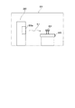
図1は、第1実施形態の圧力伝送器の構成を示す図である。この図に示す圧力伝送器1は、各種プラントにおけるプロセス流体を測定流体とした圧力測定に用いられるものであり、2点間(高圧側と低圧側)の圧力差を測定するものである。
<< First Embodiment >>
(Pressure transmitter for differential pressure measurement)
FIG. 1 is a diagram illustrating a configuration of a pressure transmitter according to the first embodiment. The
<圧力伝送器1の構成>
この圧力伝送器1は、高圧側の測定流体Fhに対応して設けられた導圧路11と、これよりも低圧側の測定流体Flに対応して設けられた導圧路11’とを備えている。これら一対の導圧路11,11’の内部には、封入液Lが充填されている。各導圧路11,11’における一方の開口は、それぞれが受圧ダイアフラム13,13’で閉塞されている。またこの圧力伝送器1は、各導圧路11,11’における他方の開口に共通に設けられた1つの圧力センサ15と、この圧力センサ15に対して並列に設けられた1つのセンタダイアフラム17とを備えている。そして特に、本第1実施形態の圧力伝送器1に特徴的な構成は、封入液Lがフェニル基を含むシリコンオイルで構成されているところ、および導圧路11,11’の内部に水素吸蔵材が設けられているところにある。
<Configuration of
The
以下、圧力伝送器1に設けられた各構成要素の詳細を、導圧路11,11’、封入液L、受圧ダイアフラム13,13’、圧力センサ15、センタダイアフラム17、水素吸蔵材の順に説明する。
Hereinafter, details of each component provided in the
[導圧路11,11’]
導圧路11,11’は、それぞれの一方の開口部分において開口径を拡大した受圧室11a,11a’を備えている。この受圧室11a,11a’によって拡大された導圧路11,11’の開口部分が、それぞれ受圧ダイアフラム13,13’によって閉塞されている。各受圧室11a,11a’は、受圧ダイアフラム13,13’の受圧による動きを妨げることのない内部形状で形成されていることとする。
[
The
また、導圧路11,11’は、受圧ダイアフラム13,13’で閉塞されている側と逆側の他方の開口部分に、その開口径を拡大した過大圧の放圧室11b,11b’を備えている。導圧路11,11’においてその開口径が拡大された形状の放圧室11b,11b’は、1つのセンタダイアフラム17を挟持して配置され、このセンタダイアフラム17によって分断された状態となっている。各放圧室11b,11b’は、センタダイアフラム17の受圧による動きを妨げることのない内部形状で形成されていることとする。
In addition, the
さらに導圧路11,11’は、分岐した経路を有しており、その分岐した導圧路11,11’の先端側の開口に圧力センサ15が設けられた構成となっている。ここで、例えば高圧側の測定流体Fhに対応して設けられた導圧路11は、放圧室11bの壁部から分岐した経路を有する。一方、低圧側の測定流体Flに対応して設けられた導圧路11’は、放圧室11b’の手前において分岐した経路を有する。
Further, the
導圧路11,11’において、これらの分岐した経路の先端側の開口は、1つの圧力センサ15を挟持して配置され、この圧力センサ15によって導圧路11,11’が分断された状態となっている。
In the
[封入液L]
封入液Lは、以上のように閉塞された一対の導圧路11,11’内に封入されたもので、受圧室11a,11a’、放圧室11b,11b’、および分岐した圧力センサ15までの部分を含む導圧路11,11’内に充填されている。これら一対の導圧路11,11’内に充填される封入液Lは、同一の種類のものであって良い。この封入液Lは、フェニル基を含むシリコンオイルであり、具体的には下記構造式(1)に示すメチルフェニルシリコンオイルである。フェニル基は、結合力が高い二重結合構造を有する基である。
[Encapsulated liquid L]
The sealed liquid L is sealed in the pair of

上記構造式(1)に示すメチルフェニルシリコンオイルは、シリコンに結合するメチル基の数に対してフェニル基の数が多いほど良く、mに対してpが大きいほど好ましい。 In the methylphenyl silicone oil represented by the structural formula (1), the larger the number of phenyl groups with respect to the number of methyl groups bonded to silicon, the better, and the larger p with respect to m is preferable.
尚、導圧路11,11’の配置環境に偏りがある場合、導圧路11,11’のうちの一方の封入液Lのみをフェニル基を含むシリコンオイルとし、他方の封入液Lを例えばジメチルシリコンオイルのような一般的なものとしても良い。
If the arrangement environment of the
[受圧ダイアフラム13,13’]
受圧ダイアフラム13,13’は、測定流体Fh,Flに対して直接晒されてその圧力を受圧するダイアフラムである。尚、測定流体Fh,Flは、この圧力伝送器1が設置される各種プラントにおけるプロセス流体である。
[Pressure-receiving
The
これらの受圧ダイアフラム13,13’は、導圧路11,11’における受圧室11a,11a’の開口を閉塞する状態で導圧路11,11’に対して固定されている。そして、一方の受圧ダイアフラム13が高圧側の測定流体Fhに対して晒され、他方の受圧ダイアフラム13’が低圧側の測定流体Flに対して晒されるように、プラントに設置される。このため、各受圧ダイアフラム13,13’は、測定流体Fh,Flに対する耐性を考慮した材質で構成されており、例えばステンレスによって構成されている。また、各受圧ダイアフラム13,13’は、例えば波形形状に加工されたものであっても良い。
These
[圧力センサ15]
圧力センサ15は、導圧路11,11’に充填された封入液Lによって伝送された圧力を検出するためのものであり、例えば半導体圧力センサである。この圧力センサ15は、半導体チップの両面に印加された圧力の差を電気信号に変換して出力するものである。このような圧力センサ15は、一方の面において、導圧路11内の封入液Lによって伝達された圧力を受け、他方の面において導圧路11’内の封入液Lによって伝達された圧力を受けるように、導圧路11,11’に挟持されている。これにより、受圧ダイアフラム13で受けた高圧側の測定流体Fhと、受圧ダイアフラム13’で受けた低圧側の測定流体Flとの圧力差が検出される構成となっている。
[Pressure sensor 15]
The
この圧力センサ15には、リード線15aを介して出力回路15bが接続される。この出力回路15bは、ここでは図示しない外部の制御装置に接続されるものである。
An
[センタダイアフラム17]
センタダイアフラム17は、加わる圧力に対応して変形量が少ない過負荷保護用のダイアフラムであって、一対の導圧路11,11’に対して圧力センサ15と並列に配置されている。このようなセンタダイアフラム17は、各導圧路11,11’に設けられた放圧室11b、11b’の開口を閉塞し、この開口において導圧路11,11’同士を隔てると共に、両側が封入液Lに晒されるように設けられている。これにより、受圧ダイアフラム13,13’のうちの一方に過大な圧力が加わった場合にも、センタダイアフラム17自身が大きく変形しないので、受圧ダイアフラム13,13’の変形量も大きくならずに破損が起こり難い構成となっている。
[Center diaphragm 17]
The
[水素吸蔵材]
水素吸蔵材は、導圧路11,11’の内部に設けられることで封入液Lに接触する状態で配置されている。ここでは特に、導圧路11,11’の配設方向に沿って水素吸蔵材が配置されていることが好ましい。
[Hydrogen storage material]
The hydrogen storage material is disposed in a state of being in contact with the sealing liquid L by being provided inside the
ここで水素吸蔵材は、水素を取り込む性質のある金属またはその合金によって構成され、水素および導圧路11,11’内において発生した炭化水素(詳しくは鎖状飽和炭化水素)中の水素原子を吸蔵する。このような水素吸蔵材は、具体的にはパラジウム、マグネシウム、バナジウム、チタン、マンガン、ジルコニウム、ニッケル、ニオブ、コバルト、カルシウム、またはそれらの合金である。
Here, the hydrogen storage material is composed of a metal having a property of taking in hydrogen or an alloy thereof, and hydrogen and hydrogen atoms generated in the hydrocarbons (specifically, chain saturated hydrocarbons) generated in the
図2は、水素吸蔵材による水素吸蔵を説明する図であり、一例として水素吸蔵材19にパラジウム(Pd)を用いた場合の水素吸蔵を説明する図である。この図に示すように、水素吸蔵材19であるパラジウムは結晶構造が面心立方格子であって、水素分子100は、パラジウム原子101の原子間に水素原子100aとして吸蔵される。このような水素吸蔵により、パラジウムは、パラジウム自体の体積の935倍の水素を吸蔵することが知られている。
FIG. 2 is a diagram for explaining hydrogen occlusion by the hydrogen occlusion material, and for explaining hydrogen occlusion when palladium (Pd) is used for the
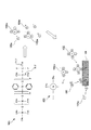
図3A〜図3Cは、導圧路11,11’における水素吸蔵材19の配置例を示す図である。以下、これらの図に基づいて導圧路11,11’の内部における水素吸蔵材19の配置状態を説明する。尚、以下で説明する図3A〜図3Cの構成の水素吸蔵材19a〜19cは、それぞれ組み合わせて用いても良い。
3A to 3C are diagrams showing examples of arrangement of the
図3Aは、導圧路11,11’内に充填された封入液Lに対して粒状の水素吸蔵材19aを混合させた構成を示す図である。このような構成により、水素吸蔵材19aが導圧路11,11’の配設方向に沿って設けられた構成となっている。
FIG. 3A is a diagram showing a configuration in which a granular hydrogen storage material 19a is mixed with the sealing liquid L filled in the
この場合、粒状の水素吸蔵材19aは、封入液Lに対して分散され、これにより封入液L中に均等に水素吸蔵材19aが混合された状態となっていることが好ましい。これにより、導圧路11,11’のほぼ全域にわたって水素吸蔵材19aの影響を及ぼすことができる。また、粒状の水素吸蔵材19aは、粒子径が小さい粉末状であっても、これよりも大きな粒子径の固形状であっても良い。水素吸蔵材19aは、径が小さくなるほど表面積が広がるため、水素の吸蔵速度を早くすることができるため好ましい。この場合、水素吸蔵材19aの粒子の大きさにより、封入液Lと混合した状態でコロイド状の液体を構成しても良い。
In this case, it is preferable that the granular hydrogen storage material 19a is dispersed with respect to the sealing liquid L so that the hydrogen storage material 19a is evenly mixed in the sealing liquid L. Thereby, the hydrogen occlusion material 19a can be influenced over almost the entire area of the
また、水素吸蔵材19aが、ある程度の大きさを有する固形状である場合、その形状が限定されることはない。この場合、水素吸蔵材19aを多孔質状のものとすることにより表面積が広がるため、水素の吸蔵速度を早くすることができるため好ましい。 In addition, when the hydrogen storage material 19a is a solid having a certain size, the shape is not limited. In this case, since the surface area is increased by making the hydrogen storage material 19a porous, it is preferable because the hydrogen storage rate can be increased.
図3Bは、導圧路11,11’の壁面に水素吸蔵材19bを設けた構成を示す図である。このような構成により、水素吸蔵材19bが導圧路11,11’の配設方向に沿って設けられた構成となっている。
FIG. 3B is a diagram showing a configuration in which a hydrogen storage material 19b is provided on the wall surfaces of the
この場合、水素吸蔵材19bは、導圧路11,11’の内壁に、例えば膜状で設けられ、メッキ法またはスパッタ法などによって成膜される。水素吸蔵材19bが設けられる導圧路11,11’の内壁は、図1を用いて説明した受圧室11a,11a’および放圧室11b,11b’において封入液Lが接触する壁面を含む。そしてこのような導圧路11,11’の内壁において、できるだけ多くの面積に水素吸蔵材19bが成膜されていることが好ましい。
In this case, the hydrogen storage material 19b is provided in the form of a film, for example, on the inner walls of the
また導圧路11,11’の壁面に水素吸蔵材19bを設ける例としては、図3Aを用いて説明した粒状の水素吸蔵材19aを、導圧路11,11’の壁面に固定する構成であっても良い。この場合、導圧路11,11’の壁面に対して粒状の水素吸蔵材19aを溶接で固定することが好適である。このような構成であれば、ある程度の大きさを有する粒状の水素吸蔵材19aが、受圧ダイアフラム13,13’やセンタダイアフラム17に衝突してそれらを劣化させることも防止できるようになる。
Further, as an example in which the hydrogen storage material 19b is provided on the wall surfaces of the
尚、センタダイアフラム17が設けられた構成においては、センタダイアフラム17に水素吸蔵材19bが設けられても良い。この場合、センタダイアフラム17において封入液Lと接する両面に水素吸蔵材19bを設けることにより、水素吸蔵材19bの表面積をさらに拡大することができる。
In the configuration in which the
図3Cは、導圧路11,11’内に、水素吸蔵材19cを敷設した構成を示す図である。水素吸蔵材19cは、例えば棒状であり、導圧路11,11’の経路に沿って敷設される。このような構成により、水素吸蔵材19cが導圧路11,11’の配設方向に沿って設けられた構成となっている。棒状の水素吸蔵材19cは、断面が円形の針金状でもよいが、それを押し広げたような幅の広い断面形状としたり、多孔質状のものとしたり、また螺旋状に敷設されたものとすることにより表面積が広がるため、水素の吸蔵速度を早くすることができるため好ましい。このような棒状の水素吸蔵材19cは、加工が容易であり、コストを抑えることができる。
FIG. 3C is a diagram showing a configuration in which a hydrogen storage material 19c is laid in the
尚、導圧路11,11’の配置環境に偏りがある場合、導圧路11,11’のうちの一方の封入液Lのみをフェニル基を含むシリコンオイルとし、内部に水素吸蔵材19を設けた構成としても良い。
In addition, when the arrangement environment of the
<圧力伝送器1の効果>
以上説明した第1実施形態の圧力伝送器1は、導圧路11,11’内に充填された封入液Lとして、フェニル基を含むシリコンオイルを用いた構成である。これにより、封入液として一般的なジメチルシリコンオイルを用いた場合と比較して、この圧力伝送器1を、放射線環境下で用いた場合においての、封入液Lの放射線分解による気体の発生が抑えられることが判った。
<Effect of
The
ここで、本第1実施形態で封入液Lとして用いるメチルフェニルシリコンオイルと、一般的に圧力伝送器の封入液として使用されるジメチルシリコンオイルとについて、放射線の照射試験を行った結果について述べる。 Here, the results of a radiation irradiation test on the methylphenyl silicone oil used as the sealing liquid L in the first embodiment and the dimethyl silicone oil generally used as the sealing liquid of the pressure transmitter will be described.
図4は、この照射試験を行った試験装置の構成図である。この図に示すように、照射試験は、放射線の照射室201内で行った。照射室201の内部には、ガンマ線hγの線源装置203、および設置台205上に載置された状態でオイル封入容器207を配置した。線源装置203は、コバルト線源からガンマ線hγを発生する装置であり、発生させたガンマ線hγを照射するための照射口203aを備えている。オイル封入容器207は、照射試験の試料となる封入液が充填されるステンレス製の容器であり、線源装置203の照射口203aから照射されるガンマ線hγの照射先に配置される。オイル封入容器207は、内部に充填される封入液に所定線量のガンマ線hγが照射されるように、線源装置203に対して所定の距離を保って配置される。
FIG. 4 is a configuration diagram of a test apparatus for performing this irradiation test. As shown in this figure, the irradiation test was performed in a
以上の試験装置を用いた照射試験は、オイル封入容器207にメチルフェニルシリコンオイルを充填した場合と、ジメチルシリコンオイルを充填した場合との2通りについて行った。
The irradiation test using the above test apparatus was performed in two ways: when the oil-sealed
所定の積算線量のガンマ線hγを照射した後には、封入液中に発生および溶存しているガスを、オイル封入容器207内から取り出し、ガスクロマトグラフィーによって成分とその量を測定した。図5は、ガスクロマトグラフィーによる分析結果を示すグラフであり、ガンマ線hγの照射量の積算である積算線量に対する発生ガス量の相対値を示すグラフである。
After irradiating a predetermined accumulated dose of gamma rays hγ, the gas generated and dissolved in the sealing liquid was taken out from the
図5のグラフに示すように、ガスクロマトグラフィーによる分析の結果、メチルフェニルシリコンオイル、ジメチルシリコンオイルともに、ガンマ線hγの照射によって、水素およびメタンが発生することを確認した。またメチルフェニルシリコンオイルからは、ベンゼンは検出されなかった。さらにメチルフェニルシリコンオイル、ジメチルシリコンオイルともに、積算線量の増加にともない、水素およびメタンの発生量が増加することを確認した。ただし、測定の記録の都合により、メチルフェニルシリコンオイルで発生するメタンは1点のみの記録になっている。 As shown in the graph of FIG. 5, as a result of analysis by gas chromatography, it was confirmed that hydrogen and methane were generated by irradiation with gamma rays hγ in both methylphenyl silicone oil and dimethyl silicone oil. Benzene was not detected from methylphenyl silicone oil. Furthermore, both methylphenyl silicone oil and dimethyl silicone oil have been confirmed to increase in the amount of hydrogen and methane generated as the integrated dose increases. However, for the convenience of recording the measurement, only one point of methane is generated from methylphenyl silicone oil.
そして、ジメチルシリコンオイルと比較して、メチルフェニルシリコンオイルの方が、水素(水素分子)およびメタンの発生量が少なかった。例えば、水素で比較すると、積算線量1kGyにおいて、メチルフェニルシリコンオイルにおいて発生する水素は、ジメチルシリコンオイルで発生する水素より発生量が4桁低かった。またメタンで比較すると、積算線量100kGyにおいて、メチルフェニルシリコンオイルで発生するメタンは、ジメチルシリコンオイルで発生するメタンより約1桁低かった。 And compared with dimethyl silicone oil, methyl phenyl silicone oil produced less hydrogen (hydrogen molecules) and methane. For example, when compared with hydrogen, hydrogen generated in methylphenyl silicone oil was 4 orders of magnitude lower than hydrogen generated in dimethyl silicone oil at an accumulated dose of 1 kGy. When compared with methane, methane generated with methylphenyl silicone oil was about an order of magnitude lower than methane generated with dimethyl silicone oil at an integrated dose of 100 kGy.
以上のように、本第1実施形態の圧力伝送器1において封入液Lとして用いたメチルフェニルシリコンオイルは、一般の圧力伝送器の封入液として使用されるジメチルシリコンオイルに比べ、放射線照射によって発生する水素および炭化水素類の発生量が少ないことが確認された。また、メチルフェニルシリコンオイルからは、ベンゼンが検出されず、放射線分解によるフェニル基の脱離も抑えられていることが確認された。
As described above, methylphenyl silicone oil used as the encapsulating liquid L in the
つまり、封入液Lをメチルフェニルシリコンオイルとすることで、一般の圧力伝送器の封入液として使用されるジメチルシリコンオイルに比べ、放射線照射によるガスの発生量を大幅に少なくできることが、今回の照射試験により初めて分かった。 In other words, by using methylphenyl silicone oil as the sealing liquid L, the amount of gas generated by radiation irradiation can be greatly reduced compared to dimethyl silicone oil used as a sealing liquid for general pressure transmitters. First discovered by testing.
さらに、図1〜図3を用いて説明した第1実施形態の圧力伝送器1は、導圧路11,11’の内部に水素吸蔵材19を設けた構成である。これにより、上述の放射試験のように、放射線環境下において、封入液Lとして用いたメチルフェニルシリコンオイルから水素原子やメチル基が脱離した場合であっても、水素吸蔵材19に水素が吸蔵される。また、受圧ダイアフラム13,13’を透過して封入液L中に取り込まれた水素も、水素吸蔵材19に吸蔵される。したがって、封入液L中におけるメタン、エタン、プロパン等の炭化水素類の濃度を低く抑えることができる。
Furthermore, the
ここで図6は、ガンマ線hγなどの放射線の照射によるメチルフェニルシリコンオイルの分解と、水素吸蔵材19による水素吸蔵を説明する図である。尚、メチルフェニルシリコンオイルからなる封入液Lへの放射線の照射は、圧力伝送器1が放射線雰囲気エリアに晒される場合の他、測定流体Fh,Flに含まれる放射線が受圧ダイアフラム13,13’を介して封入液Lに照射される場合もある。
Here, FIG. 6 is a diagram for explaining the decomposition of methylphenyl silicone oil by the irradiation of radiation such as gamma rays hγ and the hydrogen storage by the
先ず、封入液として用いられるメチルフェニルシリコンオイル103に対してガンマ線hγが照射されると、メチルフェニルシリコンオイル103におけるC−H間の結合や、Si−C間の結合が切れる。これにより、メチルフェニルシリコンオイル103から、水素原子100aやメチル基102aが脱離する。
First, when the
その後、脱離した水素原子100a、および脱離した水素原子100a同士が結合した水素分子100は、水素吸蔵材19に接触することにより水素吸蔵材19の内部に水素原子100aとして吸蔵される。これにより、水素分子100の生成が抑えられるだけではなく、メチル基102aと結合する水素原子100aの量が減少するため、メタン102の生成を抑えることができる。またメチルフェニルシリコンオイル103から脱離したメチル基102aは、再びメチルフェニルシリコンオイル103の不対結合手に結合する。これにより、封入液内における気体の発生を抑えることができる。これに対して、水素吸蔵材が設けられていない構成においては、水素分子100やメタン102の生成を抑えることができず、さらにはメチル基102aからの水素原子100aの脱離や結合により、エタン、プロパン、ブタンなどの炭化水素類も生成され、これらが気泡化して導圧路の内部の圧力を上昇させてしまうのである。
Thereafter, the desorbed
また、水素吸蔵材19が炭化水素中の水素原子を吸蔵する場合は、次のようである。すなわち、放射線分解によってメチルフェニルシリコンオイルから脱離した水素原子101aとメチル基102aの一部は、お互いが結合してメタン102となる。その後、メタン102が水素吸蔵材19の表面に接触すると、表面でメチル基102aと水素原子100aに解離する。脱離した水素原子100aは水素吸蔵材19によって吸蔵され、メチル基102aは最終的に炭素原子となって水素吸蔵材19の表面に吸着する。以上は、封入液中で生成されたエタン、プロパン、およびブタンも同様であり、これにより、メタン102のような炭化水素が気泡として蓄積することによって導圧路の内部の圧力を上昇させてしまうことを防ぐことができる。
Moreover, when the
以上より、本第1実施形態の圧力伝送器1は、封入液Lをメチルフェニルシリコンオイルとし、かつ導圧路11,11’内に水素吸蔵材19を設けたことにより、導圧路11,11’内における気体の発生を抑えることが可能である。これにより、導圧路11,11’内部の圧力の安定化を図ることができ、圧力伝達特性が長期にわたって維持されるため、指示値変動を低減して圧力伝送器1の許容誤差精度(例えば±1%の精度)を長期間保つことが可能で、圧力伝送器1の寿命を伸ばすことができる。特に、測定流体Fh,Flとなるプロセス流体の圧力が真空に近いほど、封入液Lの圧力も低下して溶解度が少なくなるため、顕著な効果を得ることができる。
As described above, the
以上の結果、圧力伝送器1の精度保持のための定期、不定期の検査等の保守作業の負担を軽減でき、許容誤差精度を保持するための交換を含めたメンテナンスコストの削減を図ることが可能になる。
As a result, it is possible to reduce the burden of maintenance work such as regular and irregular inspections for maintaining the accuracy of the
≪第2実施形態≫
(ダイアフラムに水素透過防止層を設けた差圧測定用の圧力伝送器)
図7は、第2実施形態の圧力伝送器の構成を示す図である。この図に示す圧力伝送器2は、各種プラントにおけるプロセス流体を測定流体とした圧力測定に用いられるものであり、2点間(高圧側と低圧側)の圧力差を測定するものである。
<< Second Embodiment >>
(Pressure transmitter for differential pressure measurement with a hydrogen permeation prevention layer on the diaphragm)
FIG. 7 is a diagram illustrating a configuration of a pressure transmitter according to the second embodiment. The
<圧力伝送器2の構成>
この圧力伝送器2が、図1を用いて説明した第1実施形態の圧力伝送器と異なるところは、受圧ダイアフラム13,13’に水素透過防止層21が設けられたところにあり、他の構成は同様である。このため、第1実施形態の圧力伝送器と同様の構成には同一の符号を付し、重複する説明は省略する。
<Configuration of
This
[水素透過防止層21]
水素透過防止層21は、受圧ダイアフラム13,13’に設けられたものである。この水素透過防止層21は、受圧ダイアフラム13,13’における導圧路11,11’側の表面層または受圧ダイアフラム13,13’の中間層として設けられ、測定流体Fh,Flに接触することのない状態で配置されていることが好ましい。これにより、プロセス流体である測定流体Fh,Flや、この測定流体Fh,Flが関わるプロセス系に対する水素透過防止層21の影響が抑えられる構成となっている。
[Hydrogen permeation prevention layer 21]
The hydrogen
水素透過防止層21は、水素吸蔵材または水素遮断材で構成されている。水素透過防止層21を構成する水素吸蔵材は、第1実施形態で説明した水素吸蔵材と同様の材質のものであり、測定流体Fh,Fl側からの水素を吸蔵することにより、導圧路11,11’内への水素の透過を防止している。一方、水素透過防止層21を構成する水素遮断材は、水素の吸蔵および透過自体を遮断することができる材料であり、これにより測定流体Fh,Fl側から導圧路11,11’内への水素の透過を防止している。このような水素遮断材は、具体的には金、銀、銅、白金、アルミニウム、クロム、チタン、またはこれらの合金である。
The hydrogen permeation
図8A〜図8Bは、受圧ダイアフラム13,13’における水素透過防止層21の配置例を示す図であり、図7における高圧側の受圧ダイアフラム13部分の拡大図である。以下、これらの図に基づいて受圧ダイアフラム13における水素透過防止層21の配置状態を説明する。尚、ここで説明する構成は、低圧側の受圧ダイアフラム13’も同様であるため、代表して高圧側の構成を例示して説明を行う。また、以下で説明する図8A〜図8Bの構成の水素透過防止層21a,21bは組み合わせて用いても良い。
8A to 8B are diagrams showing examples of arrangement of the hydrogen
図8Aは、受圧ダイアフラム13における導圧路11側の表面層に水素透過防止層21aを設けた構成を示す図である。水素透過防止層21aは、受圧ダイアフラム13においてできるだけ広い面を覆う状態で設けられ、これにより封止液Lに対する受圧ダイアフラム13の露出が抑えられていることが好ましい。尚、導圧路11の気密性や水素透過防止層21の耐性を確保できる場合であれば、受圧ダイアフラム13における導圧路11側の表面層の全面に水素透過防止層21を設けても良い。
FIG. 8A is a diagram showing a configuration in which a hydrogen permeation preventing layer 21 a is provided on the surface layer on the
このような水素透過防止層21aは、メッキ法またはスパッタ法などによって受圧ダイアフラム13の表面に成膜され、受圧ダイアフラム13への配置が容易である。
Such a hydrogen permeation preventing layer 21a is formed on the surface of the
図8Bは、受圧ダイアフラム13の中間層として水素透過防止層21bを設けた構成を示す図である。水素透過防止層21bは、2枚の受圧ダイアフラム13a,13b間に挟持された薄膜として設けられ、導圧路11の一方の開口である受圧室11aの開口を塞ぐ大きさであることが好ましい。このような水素透過防止層21bが水素吸蔵材で構成されている場合であれば、水素透過防止層21bは薄膜状に限定されることはなく粉末状のものを2枚の受圧ダイアフラム13a,13b間に隙間無く敷き詰めて挟持させた構成であっても良い。
FIG. 8B is a diagram showing a configuration in which a hydrogen permeation preventing layer 21 b is provided as an intermediate layer of the
このような水素透過防止層21bは、2枚の受圧ダイアフラム13a,13b間に膜状または粉末状の水素透過防止層21bを挟持した状態で圧延して一体化させることにより、受圧ダイアフラム13の中間層として一体に形成される。またこのような水素透過防止層21bは、測定流体Fh,Flに対してだけではなく、封入液Lに対しても何ら影響を及ぼすことがない。
Such a hydrogen permeation preventing layer 21b is rolled and integrated in a state where a film-like or powdery hydrogen permeation preventing layer 21b is sandwiched between the two
尚、測定流体Fh,Flの性質に偏りがある場合、受圧ダイアフラム13,13’のうちの一方のみに水素透過防止層21を設けても良い。また導圧路11,11’の配置環境に偏りがあり、導圧路11,11’のうちの一方の封入液Lのみをフェニル基を含むシリコンオイルとし、内部に水素吸蔵材19を設けている場合、水素吸蔵材19を設けた側に水素透過防止層21を設けることで、以下で説明するような相乗的な効果が得られる。
When the properties of the measurement fluids Fh and Fl are biased, the hydrogen
<圧力伝送器2の効果>
以上のような第2実施形態の圧力伝送器2によれば、受圧ダイアフラム13,13’に水素透過防止層21を設けたことにより、測定流体Fh,Flに含有される水素が導圧路11,11’に充填された封入液Lに混入することを防止できる。したがって、第1実施形態の効果に加えて、さらに水素濃度が高いプロセス流体を測定流体Fh,Flとする場合であっても、十分に導圧路11,11’内部の圧力の安定化を図ることができ、圧力伝達特性を長期にわたって維持することが可能となる。
<Effect of
According to the
ここで、単に受圧ダイアフラム13,13’に水素透過防止層21を設けただけの構成であれば、封入液Lの分解によって発生した水素や炭化水素類が外部に放出されず、導圧路11,11’の内部の圧力を安定化させることはできない。この問題点を解決するために、封入液Lの分解による水素や炭化水素類の発生そのものを抑制することが重要である。このために、封入液Lをフェニル基を含むメチルフェニルシリコンオイルにすることで、封入液Lの分解による水素及び炭化水素類の発生を抑制している。さらに、それでも放射線照射によって発生した水素、及び炭化水素中の水素原子の両方を、水素吸蔵材19で吸蔵することで、封入液L内における気体の発生を防止することにより、圧力伝送器2における圧力伝達特性の変動を抑制することを可能にしている。
Here, if only the hydrogen
尚、水素透過防止層21として水素吸蔵材を用いた場合であれば、封入液Lから脱離した水素、および封入液Lから脱離した炭化水素中の水素原子が、この水素透過防止層21において吸蔵されることにより、導圧路11,11’の内部の圧力の安定化が図られる。
In the case where a hydrogen storage material is used as the hydrogen permeation
≪第3実施形態≫
(絶対圧力測定用の圧力伝送器)
図9は、第3実施形態の圧力伝送器の構成を示す図である。この図に示す圧力伝送器3は、各種プラントにおけるプロセス流体を測定流体とした圧力測定に用いられるものであり、測定流体Fの圧力を測定する絶対圧力測定用のものである。
«Third embodiment»
(Pressure transmitter for absolute pressure measurement)
FIG. 9 is a diagram illustrating a configuration of a pressure transmitter according to the third embodiment. The
<圧力伝送器3の構成>
この圧力伝送器3が、図1を用いて説明した第1実施形態の圧力伝送器と異なるところは、1つの圧力センサ15に対して、1つの受圧ダイアフラム13と、1つの導圧路11とのみを有しているところにある。そして圧力センサ15の一方の面側のみに導圧路11の他方の開口が配置され、導圧路11の一方の開口に設けられた受圧ダイアフラム13で受けた測定流体Fの圧力が検出される構成となっている。他の構成は、第1実施形態と同様である。
<Configuration of
The
尚、以上のような第3実施形態の圧力伝送器3は、図7,8を用いて説明した第2実施形態と組み合わせても良く、受圧ダイアフラム13に水素透過防止層を設けても良い。
The
<圧力伝送器3の効果>
以上のような第3実施形態の圧力伝送器3であっても、第1実施形態および第2実施形態で説明したと同様の効果を得ることができる。
<Effect of
Even with the
≪第4実施形態≫
(中間ダイアフラムを備えた圧力伝送器)
図10は、第4実施形態の圧力伝送器の構成を示す図である。この図に示す圧力伝送器4は、各種プラントにおけるプロセス流体を測定流体とした圧力測定において、特に高温環境下に適して用いられるものであり、ここでは2点間(高圧側と低圧側)の圧力差を測定するものとして説明を行う。
<< Fourth Embodiment >>
(Pressure transmitter with intermediate diaphragm)
FIG. 10 is a diagram illustrating a configuration of a pressure transmitter according to the fourth embodiment. The
<圧力伝送器4の構成>
この圧力伝送器4が、図1を用いて説明した第1実施形態の圧力伝送器と異なるところは、導圧路11,11’が複数の管体部分41,42,…、41’,42’…を接続して構成されたもので、その接続部に中間ダイアフラム40が設けられているところにある。他の構成は同様である。このため、第1実施形態の圧力伝送器と同様の構成には同一の符号を付し、重複する説明は省略する。
<Configuration of
The
[導圧路11,11’]
導圧路11,11’は、直列に接続された複数本の管体部分41,42,…、41’,42’,…を備えている。図示した例においては、導圧路11が3本の管体部分41,42,43で構成され、導圧路11’が3本の管体部分41’,42’,43’で構成されている。各管体部分41〜43’は、それぞれが測定流体Fh,Flの受圧側の開口部分において開口径を拡大した受圧室11a,11a’を構成し、他方の開口部分において開口径を拡大した放圧室11b,11b’を構成している。
[Pressure guiding
The
そして、導圧路11,11’において最も測定流体Fh,Fl側に配置される管体部分41,41’は、置換器部を構成する。この管体部分41,41’における受圧室11a,11a’の開口部分が、それぞれ受圧ダイアフラム13,13’によって閉塞されている。一方、導圧路11,11’において最も圧力センサ15側に配置される各管体部分43,43’は、圧力センサ15を有する本体部を構成する。この管体部分43,43’における放圧室11b,11b’の開口部分が、1つのセンタダイアフラム17を挟持して配置され、このセンタダイアフラム17によって閉塞された状態となっている。
The
また、各導圧路11,11’の中央に配置された管体部分42,42’は、置換器部を構成する管体部分41,41’と、本体部を構成する管体部分43,43’との接続部位であるキャピラリ部を構成する。
In addition, the
各管体部分41,42,43、41’,42’,43’同士の接続部は、放圧室11bの開口と受圧室11aの開口とを対向させて配置し、この対向部分に中間ダイアフラム40が挟持され、各中間ダイアフラム40によって閉塞された状態となっている。つまり、導圧路11,11’は、複数の管体部分41,42,43、41’,42’,43’を接続した構成ではあるが、それぞれの内部空間は中間ダイアフラム40によって分断された状態となっている。
The connecting portions of the
そして、受圧ダイアフラム13,13’、圧力センサ15、センタダイアフラム17、および中間ダイアフラム40によって独立して閉塞された各管体部分41,42,43、41’,42’,43’に、それぞれ封入液Lが充填された状態となっている。この封入液Lは、第1実施形態と同様のフェニル基を含むシリコンオイルである。また、導圧路11,11’を構成する各管体部分41,42,43、41’,42’,43’には、それぞれ第1実施形態と同様の水素吸蔵材が同様の配置状態で設けられている。
And it encloses in each
尚、ここでは、全ての管体部分41,42,43、41’,42’,43’において、封入液Lがフェニル基を含むシリコンオイルであって内部に水素吸蔵材19が設けられている構成であることに限定されず、選択された管体部分のみにこの構成を適用しても良い。
Here, in all the
[中間ダイアフラム40]
中間ダイアフラム40は、受圧ダイアフラム13,13’から圧力センサ15にわたって配置された導圧路11,11’の中間部に設けられたものあって、過大圧による受圧ダイアフラム13,13’および圧力センサ15の破壊を防止するためのものである。このような中間ダイアフラム40は、各導圧路11,11’の中間部を閉塞することにより、各導圧路11,11’を複数の管体部分41,42,43、41’,42’,43’に分断すると共に、両側が各封入液Lに晒されるように設けられている。これにより、受圧ダイアフラム13,13’のうちの一方に過大な圧力が加わった場合にも、中間ダイアフラム40が過大圧の緩衝材となって、受圧ダイアフラム13,13’および圧力センサ15の破壊が起こり難い構成となっている。尚、中間ダイアフラム40のうち、最も圧力センサ15に近く配置されたものは、シールダイアフラムとして本体部を構成する。
[Intermediate diaphragm 40]
The
このような中間ダイアフラム40にも、水素吸蔵材が設けられて良い。この場合、中間ダイアフラム40において封入液Lと接する両面に水素吸蔵材を設けることにより、水素吸蔵材の表面積をさらに拡大することができる。
Such an
尚、以上のような第4実施形態の圧力伝送器4は、図7,8を用いて説明した第2実施形態と組み合わせて受圧ダイアフラム13,13’に水素透過防止層を設けても良い。また、図9を用いて説明した第3実施形態と同様に、導圧路11,11’の一方のみを用いることにより絶対圧力測定用とすることができる。
The
<圧力伝送器4の効果>
以上のような第4実施形態の圧力伝送器4は、高温環境で使用されるものであるため、使用時においては瞬時的に高温(例えば300℃を超える)雰囲気に晒される場合もある。このような場合であっても、圧力伝送器4は、封入液Lがフェニル基を含むシリコンオイルであり、導圧路11,11’を構成する各管体部分41,42,43、41’,42’,43’に水素吸蔵材を設けた構成であるため、第1実施形態と同様に、封入液Lの熱分解による気泡の発生を防止することができ、圧力伝達特性を長期にわたって維持することが可能となる。また、第2実施形態と組み合わせて受圧ダイアフラム13,13’に水素透過防止層を設けた構成とすることにより、第2実施形態の効果を得ることができる。
<Effect of
Since the
≪第5実施形態≫
(原子力プラントにおける圧力伝送器の適用例)
図11は、原子力プラントにおける圧力伝送器の適用例を示す図であり、沸騰水型の原子力プラント(Boiling Water Reactor:BWR)における給水系及び復水系の構成を示す図である。以下この図に基づいて、原子力プラントの給水系及び復水系におけるプロセス計測の一例として、給水加熱器のドレンタンクの水位計測に圧力伝送器を用いる例を示している。
«Fifth embodiment»
(Application example of pressure transmitter in nuclear power plant)
FIG. 11 is a diagram illustrating an application example of a pressure transmitter in a nuclear power plant, and is a diagram illustrating configurations of a water supply system and a condensate system in a boiling water reactor (Boiling Water Reactor: BWR). In the following, based on this figure, as an example of process measurement in the feed water system and condensate system of a nuclear power plant, an example is shown in which a pressure transmitter is used to measure the water level in the drain tank of the feed water heater.
この図に示すように、原子力プラント5は、核燃料の集合体である炉心51を、炉水52に浸漬させた状態で収容する圧力容器53を備えている。圧力容器53には、主蒸気配管54を介して高圧タービン55が接続され、この高圧タービン55には湿分分離加熱器56を介して低圧タービン57が接続されている。高圧タービン55と、低圧タービン57とは同軸状に配置され、さらにこれらのタービンによって稼働する発電機58が接続されている。湿分分離加熱器56には、ドレン配管59を介してドレンタンク60が設けられている。
As shown in this figure, the
また低圧タービン57には復水器61が設けられており、復水器61内には冷却管62が配設されている。この復水器61と圧力容器53とが復水配管63を介して接続された状態となっている。復水配管63には、復水器61側から順に、復水ポンプ64、給水加熱器65、給水ポンプ66が設けられており、圧力容器53と高圧タービン55および低圧タービン57との間で炉水52を循環させている。また、給水加熱器65には、ドレン配管67を介してドレンタンク68が設けられ、ドレンタンク68は給水配管69とドレンポンプ70とによって復水配管63の復水器61側に接続されている。
The low-
以上のような構成の原子力プラント5においては、例えば給水加熱器65のドレンタンク68の水位計測に圧力伝送器が用いられている。この圧力伝送器として、例えば先に図1を用いて説明した第1実施形態の圧力伝送器1を適用する。
In the
この場合、ドレンタンク68の上流側の配管を流れる流体、すなわちドレンタンク68と復水器61との間の給水配管69に流れる流体を高圧側の測定流体Fhとして、圧力伝送器1における一方の受圧ダイアフラム13に供給する。またドレンタンク68の下流側の配管を流れる流体、すなわちドレンタンク68と給水加熱器65との間のドレン配管67を流れる流体を低圧側の測定流体Flとして、圧力伝送器1における他方の受圧ダイアフラム13’に供給する。
In this case, the fluid flowing through the pipe on the upstream side of the
これにより、ドレンタンク68の上流側と下流側の差圧が、圧力伝送器1の圧力センサ15で受圧されて出力回路15bに出力される構成となっている。
Accordingly, the differential pressure between the upstream side and the downstream side of the
原子力プラント5においては、出力回路15bからの情報が制御装置71を介して中央制御室72に伝達される構成となっている。そして、出力回路15bに出力された情報(差圧)がドレンタンク68の水位としてモニターされ、この値に基づいてドレンタンク68の水位が所定値となるように制御がなされる。
In the
以上説明した原子力プラント5の給水系及び復水系は、放射線量が高い特殊環境であり、このドレンタンク68の水位計測に設けた圧力伝送器1においては封入液Lが放射線分解し易い環境である。そこで、第1実施形態の圧力伝送器1を適用することにより、先に説明したように導圧路11,11’内におけるガスの発生が抑えられ、放射線環境下であっても長期間の測定精度を確保することが可能であり、またこれによりメンテナンスのコストを削減することが可能になる。
The feed water system and the condensate system of the
尚、ここではドレンタンク68の水位計測に第1実施形態の圧力伝送器1を用いた構成を例示した。しかしながら、原子力プラント5に設けられる圧力伝送器はこれに限定されず、第2実施形態(図7,8)および第4実施形態(図10)で説明した構成や、これらを組み合わせた圧力伝送器を用いることができ、それぞれの実施形態の効果を発揮することができる。
Here, a configuration in which the
特に、原子力プラント5における給水系及び復水系では、炉心51を直接冷却する炉水52が測定流体であり、放射線分解等で発生した水素を多量に含んだものとなる。この炉水52は、蒸気として主蒸気配管54から、湿分分離加熱器56、ドレンタンク60、給水加熱器65、復水器61、およびドレンタンク68などに導入される。蒸気として導入された炉水52は、湿分分離加熱器56および給水加熱器65等により凝縮し、凝縮水となる。一方で、蒸気に含まれた非凝縮性の水素は、比重が飽和蒸気の比重より小さいため上部に蓄積され、次第に高濃度となる。測定流体である炉水52の上部に蓄積した水素は、濃度が高くなるほど受圧ダイアフラム13,13’を透過しやすくなる。
In particular, in the water supply system and the condensate system in the
したがって、特に原子力プラント5における給水系及び復水系のプロセス計測には、図7および図8を用いて説明した第2実施形態の圧力伝送器2、すなわち受圧ダイアフラム13,13に水素透過防止層21を設けたものを用いることにより、導圧路11,11’内への水素の侵入を防止することも、測定精度を長期間にわたって確保する上で有効になる。
Therefore, particularly for the process measurement of the feed water system and the condensate system in the
また、以上においては、給水加熱器65のドレンタンク68の水位計測に、圧力伝送器1を用いた構成を例示した。しかしながら、原子力プラント5における圧力伝送器1の設置箇所がこれに限定されることはなく、特に炉心51を直接冷却する炉水52を測定流体とした各種のプロセス計測に対して圧力伝送器1を用いることが有効である。例えば、湿分分離加熱器56のドレンタンク60および復水器61の水位計測、さらには主蒸気配管54や復水配管63の流量計測などにおいて、圧力伝送器1を用いることにより同様に十分な効果を発揮することができる。これらの各プロセス計測には、第1実施形態〜第4実施形態の構成およびこれらを組み合わせた構成の圧力伝送器が用いられる。ただし、絶対圧力の計測には、第3実施形態で説明した構成またはこれと組み合わせた構成のものが用いられる。
Moreover, in the above, the structure which used the
また本発明の圧力伝送器が設けられる原子力プラントは、上述した沸騰水型に限定されることはなく、例えば加圧水型の原子力プラント(Pressurized Water Reactor:PWR)であっても良い。この場合も同様に、炉心を直接冷却する炉水(一次冷却水)を測定流体とした各種のプロセス計測に対して、本発明の圧力伝送器を用いることにより、同様の効果を得ることができる。 Further, the nuclear power plant provided with the pressure transmitter of the present invention is not limited to the boiling water type described above, and may be, for example, a pressurized water nuclear power plant (Pressurized Water Reactor: PWR). In this case as well, the same effect can be obtained by using the pressure transmitter of the present invention for various process measurements using reactor water (primary cooling water) for directly cooling the core as a measurement fluid. .
以上、本発明の実施の形態について説明した。しかし、本発明は、上述の実施の形態に限定されるものではなく、特許請求の範囲に記載した発明の要旨を逸脱しない範囲内で種々の変形実施が可能である。
例えば、上記した実施の形態例は本発明を分かりやすく説明するために装置及びシステムの構成を詳細且つ具体的に説明したものであり、必ずしも説明した全ての構成を備えるものに限定されるものではない。また、ある実施形態の構成の一部を他の実施形態の構成に置き換えることは可能であり、更にはある実施形態例の構成に他の実施形態例の構成を加えることも可能である。また、各実施形態例の構成の一部について、他の構成の追加、削除、置換をすることも可能である。
また、制御線や情報線は説明上必要と考えられるものを示しており、製品上必ずしも全ての制御線や情報線を示しているとは限らない。実際には殆ど全ての構成が相互に接続されていると考えてもよい。
The embodiment of the present invention has been described above. However, the present invention is not limited to the above-described embodiments, and various modifications can be made without departing from the spirit of the invention described in the claims.
For example, in the above-described embodiment, the configuration of the apparatus and the system is described in detail and specifically in order to explain the present invention in an easy-to-understand manner. Absent. A part of the configuration of an embodiment can be replaced with the configuration of another embodiment, and the configuration of another embodiment can be added to the configuration of an embodiment. Moreover, it is also possible to add, delete, and replace other configurations for a part of the configuration of each exemplary embodiment.
Further, the control lines and information lines indicate what is considered necessary for the explanation, and not all the control lines and information lines on the product are necessarily shown. Actually, it may be considered that almost all the components are connected to each other.
1,2,3,4…圧力伝送器
11,11’…導圧路
11a,11a’…受圧室(導圧路)
11b,11b’…放圧室(導圧路)
13,13’…受圧ダイアフラム
15…圧力センサ
17…センタダイアフラム
19,19a,19b,19c…水素吸蔵材
21,21a,21b…水素透過防止層
40…中間ダイアフラム
41,41,42,41’,42’,43’…管体部分
F…測定流体
Fh…測定流体(高圧側)
Fl…測定流体(低圧側)
L…封入液
1, 2, 3, 4 ...
11b, 11b '... pressure release chamber (pressure guiding path)
DESCRIPTION OF
Fl ... Measurement fluid (low pressure side)
L: Filling liquid
Claims (15)
前記導圧路内に充填された封入液と、
前記導圧路における一方の開口を閉塞する状態で設けられ測定流体の圧力を受圧する受圧ダイアフラムと、
前記封入液に晒された状態で前記導圧路における他方の開口に設けられた圧力センサとを備え、
前記封入液がフェニル基を含むシリコンオイルであり、
前記導圧路の内部に設けられた水素吸蔵材を有する
圧力伝送器。 A tubular pressure conduit,
A sealing liquid filled in the pressure guiding path;
A pressure receiving diaphragm which is provided in a state of closing one opening in the pressure guiding path and receives the pressure of the measurement fluid;
A pressure sensor provided at the other opening of the pressure guiding path in a state exposed to the sealing liquid,
The sealing liquid is a silicone oil containing a phenyl group,
A pressure transmitter having a hydrogen storage material provided inside the pressure guiding path.
請求項1記載の圧力伝送器。 The pressure transmitter according to claim 1, wherein the silicone oil is methylphenyl silicone oil.
請求項1記載の圧力伝送器。 The pressure transmitter according to claim 1, wherein the hydrogen storage material stores hydrogen and hydrogen atoms in hydrocarbons generated in the pressure guiding path.
請求項1記載の圧力伝送器。 The pressure transmitter according to claim 1, wherein the hydrogen storage material is disposed along an arrangement direction of the pressure guiding path.
請求項4記載の圧力伝送器。 The pressure transmitter according to claim 4, wherein the hydrogen storage material is mixed in the sealing liquid.
請求項4記載の圧力伝送器。 The pressure transmitter according to claim 4, wherein the hydrogen storage material is provided on an inner wall of the pressure guiding path.
請求項4記載の圧力伝送器。 The pressure transmitter according to claim 4, wherein the hydrogen storage material is laid in the pressure guiding path.
請求項1記載の圧力伝送器。 The pressure transmitter according to claim 1, wherein the hydrogen storage material is palladium, magnesium, vanadium, titanium, manganese, zirconium, nickel, niobium, cobalt, calcium, or an alloy thereof.
請求項1〜8の何れかに記載の圧力伝送器。 The pressure transmitter according to claim 1, wherein a hydrogen permeation prevention layer is provided on the pressure receiving diaphragm.
請求項9記載の圧力伝送器。 The pressure transmitter according to claim 9, wherein the hydrogen permeation preventing layer is provided as a surface layer on the pressure guiding path side in the pressure receiving diaphragm or an intermediate layer of the pressure receiving diaphragm.
請求項9記載の圧力伝送器。 The pressure transmitter according to claim 9, wherein the hydrogen permeation preventive layer is made of a hydrogen storage material or a hydrogen barrier material.
請求項9記載の圧力伝送器。 The pressure transmitter according to claim 9, wherein the hydrogen permeation preventive layer is made of gold, silver, copper, platinum, aluminum, chromium, titanium, or an alloy thereof.
請求項1記載の圧力伝送器。 2. The pressure transmitter according to claim 1, wherein a pair of the pressure guiding paths filled with the sealing liquid and having one opening closed with the pressure receiving diaphragm are arranged in a state of sandwiching the pressure sensor from both sides.
請求項13記載の圧力伝送器。 The pressure transmitter according to claim 13, further comprising: a center diaphragm sandwiched in parallel with the pressure sensor with respect to the pair of pressure guiding paths, wherein the center diaphragm is provided with the hydrogen storage material.
前記中間ダイアフラムに前記水素吸蔵材が設けられた
請求項1記載の圧力伝送器。
The pressure guiding path includes a plurality of tube portions connected in series, and an intermediate diaphragm provided at a connection portion of each tube portion,
2. The pressure transmitter according to claim 1, wherein the hydrogen storage material is provided on the intermediate diaphragm.
Priority Applications (4)
| Application Number | Priority Date | Filing Date | Title |
|---|---|---|---|
| JP2013217139A JP2015078945A (en) | 2013-10-18 | 2013-10-18 | Pressure transmission device |
| EP14189258.8A EP2863198A3 (en) | 2013-10-18 | 2014-10-16 | Pressure transmitter |
| US14/516,115 US20150107365A1 (en) | 2013-10-18 | 2014-10-16 | Pressure Transmitter |
| CN201410551141.2A CN104568285A (en) | 2013-10-18 | 2014-10-17 | Pressure transmitter |
Applications Claiming Priority (1)
| Application Number | Priority Date | Filing Date | Title |
|---|---|---|---|
| JP2013217139A JP2015078945A (en) | 2013-10-18 | 2013-10-18 | Pressure transmission device |
Publications (2)
| Publication Number | Publication Date |
|---|---|
| JP2015078945A true JP2015078945A (en) | 2015-04-23 |
| JP2015078945A5 JP2015078945A5 (en) | 2016-04-14 |
Family
ID=51726435
Family Applications (1)
| Application Number | Title | Priority Date | Filing Date |
|---|---|---|---|
| JP2013217139A Pending JP2015078945A (en) | 2013-10-18 | 2013-10-18 | Pressure transmission device |
Country Status (4)
| Country | Link |
|---|---|
| US (1) | US20150107365A1 (en) |
| EP (1) | EP2863198A3 (en) |
| JP (1) | JP2015078945A (en) |
| CN (1) | CN104568285A (en) |
Cited By (1)
| Publication number | Priority date | Publication date | Assignee | Title |
|---|---|---|---|---|
| KR101996987B1 (en) * | 2018-07-09 | 2019-07-08 | 한국원자력연구원 | Pressure transmitter |
Families Citing this family (5)
| Publication number | Priority date | Publication date | Assignee | Title |
|---|---|---|---|---|
| JP6018945B2 (en) * | 2012-10-05 | 2016-11-02 | 株式会社日立製作所 | Transmission apparatus and transmission method |
| JP2015078944A (en) * | 2013-10-18 | 2015-04-23 | 株式会社日立製作所 | Pressure transmission device |
| JP6199765B2 (en) * | 2014-02-13 | 2017-09-20 | 株式会社日立製作所 | Nuclear plant instrumentation equipment |
| JP6478776B2 (en) * | 2015-04-10 | 2019-03-06 | 株式会社日立製作所 | Pressure transmission device |
| CN107478376A (en) * | 2017-09-25 | 2017-12-15 | 无锡市凯丰压力表有限公司 | A kind of resistant to elevated temperatures pressure gauge of anti-condensation |
Citations (5)
| Publication number | Priority date | Publication date | Assignee | Title |
|---|---|---|---|---|
| JPS5263188A (en) * | 1975-11-18 | 1977-05-25 | Terukatsu Miyauchi | Method of separating mixed gas |
| JPH09113394A (en) * | 1995-10-16 | 1997-05-02 | Hitachi Ltd | Pressure transmitter |
| JP2003156399A (en) * | 2001-11-22 | 2003-05-30 | Toyoda Mach Works Ltd | Semiconductor pressure detector |
| JP2004361159A (en) * | 2003-06-03 | 2004-12-24 | Fuji Electric Systems Co Ltd | Remote seal type pressure/differential pressure transmitter |
| CN202938959U (en) * | 2012-05-22 | 2013-05-15 | 罗斯蒙德公司 | Pressure transmitter provided with hydrogen getter |
Family Cites Families (14)
| Publication number | Priority date | Publication date | Assignee | Title |
|---|---|---|---|---|
| JPS5943725B2 (en) * | 1975-05-05 | 1984-10-24 | ポラロイド、コ−ポレ−シヨン | camera exposure control device |
| US4820226A (en) * | 1987-10-14 | 1989-04-11 | The United States Of America As Represented By The United States Department Of Energy | Getter pump for hydrogen and hydrocarbon gases |
| JPH0652213B2 (en) * | 1988-09-02 | 1994-07-06 | 株式会社日立製作所 | Differential pressure transmission line |
| US6682609B1 (en) * | 1994-07-22 | 2004-01-27 | Kabushiki Kaisha Toshiba | Hydrogen absorbing alloy, method of surface modification of the alloy, negative electrode for battery and alkaline secondary battery |
| US5885378A (en) * | 1995-07-12 | 1999-03-23 | Mitsubishi Materials Corporation | Hydrogen occluding alloy and electrode made of the alloy |
| US5837158A (en) * | 1996-09-23 | 1998-11-17 | Sandia Corporation | Polymer formulations for gettering hydrogen |
| JPH11300196A (en) * | 1998-04-27 | 1999-11-02 | Sanyo Electric Co Ltd | Hydrogen discharger and device utilizing the discharger |
| JP2001116644A (en) * | 1999-10-22 | 2001-04-27 | Fuji Electric Co Ltd | Semiconductor type sensor |
| JP2005114453A (en) * | 2003-10-06 | 2005-04-28 | Yokogawa Electric Corp | Differential pressure measuring system |
| US7290452B2 (en) * | 2003-12-16 | 2007-11-06 | Rosemount Inc. | Remote process seal with improved stability in demanding applications |
| US7918134B2 (en) * | 2008-10-06 | 2011-04-05 | Rosemount Inc. | Thermal-based diagnostic system for process transmitter |
| NO20111218A1 (en) * | 2011-09-08 | 2013-02-25 | Presens As | Retractable pressure sensor |
| JP2015078944A (en) * | 2013-10-18 | 2015-04-23 | 株式会社日立製作所 | Pressure transmission device |
| JP6199765B2 (en) * | 2014-02-13 | 2017-09-20 | 株式会社日立製作所 | Nuclear plant instrumentation equipment |
-
2013
- 2013-10-18 JP JP2013217139A patent/JP2015078945A/en active Pending
-
2014
- 2014-10-16 US US14/516,115 patent/US20150107365A1/en not_active Abandoned
- 2014-10-16 EP EP14189258.8A patent/EP2863198A3/en not_active Withdrawn
- 2014-10-17 CN CN201410551141.2A patent/CN104568285A/en active Pending
Patent Citations (5)
| Publication number | Priority date | Publication date | Assignee | Title |
|---|---|---|---|---|
| JPS5263188A (en) * | 1975-11-18 | 1977-05-25 | Terukatsu Miyauchi | Method of separating mixed gas |
| JPH09113394A (en) * | 1995-10-16 | 1997-05-02 | Hitachi Ltd | Pressure transmitter |
| JP2003156399A (en) * | 2001-11-22 | 2003-05-30 | Toyoda Mach Works Ltd | Semiconductor pressure detector |
| JP2004361159A (en) * | 2003-06-03 | 2004-12-24 | Fuji Electric Systems Co Ltd | Remote seal type pressure/differential pressure transmitter |
| CN202938959U (en) * | 2012-05-22 | 2013-05-15 | 罗斯蒙德公司 | Pressure transmitter provided with hydrogen getter |
Cited By (1)
| Publication number | Priority date | Publication date | Assignee | Title |
|---|---|---|---|---|
| KR101996987B1 (en) * | 2018-07-09 | 2019-07-08 | 한국원자력연구원 | Pressure transmitter |
Also Published As
| Publication number | Publication date |
|---|---|
| EP2863198A3 (en) | 2015-08-19 |
| EP2863198A2 (en) | 2015-04-22 |
| CN104568285A (en) | 2015-04-29 |
| US20150107365A1 (en) | 2015-04-23 |
Similar Documents
| Publication | Publication Date | Title |
|---|---|---|
| JP6199765B2 (en) | Nuclear plant instrumentation equipment | |
| JP2015078944A (en) | Pressure transmission device | |
| JP2015078945A (en) | Pressure transmission device | |
| JP6018945B2 (en) | Transmission apparatus and transmission method | |
| JP2015152373A5 (en) | ||
| JP6130764B2 (en) | Pressure measuring device and pressure measuring method | |
| JP2004361159A (en) | Remote seal type pressure/differential pressure transmitter | |
| US20180099246A1 (en) | Hydrogen sensing and separation | |
| US9939339B2 (en) | Pressure transmitter device | |
| US10809147B2 (en) | System and method for monitoring hydrogen flux | |
| Glatzmaier et al. | Sensor for measuring hydrogen partial pressure in parabolic trough power plant expansion tanks | |
| Lee et al. | Effects of temperature and pressure on Henry’s law constant for hydrogen in the primary water of a simulated pressurized-water reactor | |
| JP2018091806A (en) | Vent flow rate measurement system of reactor containment vessel | |
| Kuwana et al. | ICONE23-1424 DEVELOPMENT OF METHOD OF DRIFT SUPPRESSION FOR PRESSURE TRANSMITTERS CONTAINING PALLADIUM | |
| JP2022062621A (en) | Diaphragm seal and maintenance method therefor | |
| JP6660821B2 (en) | Pressure transmission device and pressure transmission method | |
| JP2015096806A (en) | Transmission device | |
| Glatzmaier | Acciona power plant hydrogen mitigation project | |
| BR112018008070B1 (en) | SENSOR FOR MEASURING THE RISK OF FRAGILE BY HYDROGEN OF AN INDUSTRIAL EQUIPMENT TO BE EVALUATED | |
| JPH07260612A (en) | Pressure transmitter | |
| JP6283266B2 (en) | Pressure measuring device | |
| Glatzmaier | Abengoa/Acciona Power Plant Hydrogen Mitigation Project (Cooperative Research and Development Final Report, CRADA Number CRD-15-583) | |
| JP2015145859A (en) | Hydrogen gas concentration monitoring system and hydrogen gas concentration monitoring method | |
| Koc et al. | Process Safety Aspects in Water-Gas-Shift (WGS) Catalytic Membrane Reactors Used for Pure Hydrogen Production | |
| JP2017111015A (en) | Hydrogen measurement device and hydrogen measurement method |
Legal Events
| Date | Code | Title | Description |
|---|---|---|---|
| A521 | Request for written amendment filed |
Free format text: JAPANESE INTERMEDIATE CODE: A523 Effective date: 20160226 |
|
| A621 | Written request for application examination |
Free format text: JAPANESE INTERMEDIATE CODE: A621 Effective date: 20160226 |
|
| A977 | Report on retrieval |
Free format text: JAPANESE INTERMEDIATE CODE: A971007 Effective date: 20161215 |
|
| A131 | Notification of reasons for refusal |
Free format text: JAPANESE INTERMEDIATE CODE: A131 Effective date: 20161227 |
|
| A521 | Request for written amendment filed |
Free format text: JAPANESE INTERMEDIATE CODE: A523 Effective date: 20170118 |
|
| A02 | Decision of refusal |
Free format text: JAPANESE INTERMEDIATE CODE: A02 Effective date: 20170627 |