JP2015073723A - Mirror cabinet - Google Patents

Mirror cabinet Download PDF

Info

Publication number
JP2015073723A
JP2015073723A JP2013211656A JP2013211656A JP2015073723A JP 2015073723 A JP2015073723 A JP 2015073723A JP 2013211656 A JP2013211656 A JP 2013211656A JP 2013211656 A JP2013211656 A JP 2013211656A JP 2015073723 A JP2015073723 A JP 2015073723A
Authority
JP
Japan
Prior art keywords
mirror
mirror cabinet
locking
fixing member
cabinet body
Prior art date
Legal status (The legal status is an assumption and is not a legal conclusion. Google has not performed a legal analysis and makes no representation as to the accuracy of the status listed.)
Pending
Application number
JP2013211656A
Other languages
Japanese (ja)
Inventor
秋山 浩史
Hiroshi Akiyama
秋山  浩史
Current Assignee (The listed assignees may be inaccurate. Google has not performed a legal analysis and makes no representation or warranty as to the accuracy of the list.)
Noritz Corp
Kanto Sangyo Co Ltd
Original Assignee
Noritz Corp
Kanto Sangyo Co Ltd
Priority date (The priority date is an assumption and is not a legal conclusion. Google has not performed a legal analysis and makes no representation as to the accuracy of the date listed.)
Filing date
Publication date
Application filed by Noritz Corp, Kanto Sangyo Co Ltd filed Critical Noritz Corp
Priority to JP2013211656A priority Critical patent/JP2015073723A/en
Publication of JP2015073723A publication Critical patent/JP2015073723A/en
Pending legal-status Critical Current

Links

Images

Landscapes

  • Mirrors, Picture Frames, Photograph Stands, And Related Fastening Devices (AREA)

Abstract

PROBLEM TO BE SOLVED: To provide a mirror cabinet having a simple structure, enabling surely inserting a fixation member into an engaging hole to engage, and surely fastening a mirror on a mirror cabinet body without being carelessly dropped.SOLUTION: A mirror cabinet includes a mirror 3, a mirror cabinet body 2, and a fixation member 6. The fixation member 6 includes a mirror holding part 12 having a front wall 17 and a bottom surface wall 18 and formed in a nearly L shape in a side view, a back surface part 13 standing from the bottom surface wall 18 of the mirror holding part 12, and an engaging part 14 inserted into an engaging hole 22 formed on the mirror cabinet body 2, and formed in an arrowhead shape in a plane view. The engaging part 14 has a shaft part 24, and an engaging piece 25 continuously formed from the tip of the shaft part 24, and is formed so as to protrude from a circular pedestal part 19 formed on the back surface part 13.

Description

本発明は、ミラーキャビネットに関し、特に鏡の固定構造に特徴を有するミラーキャビネットに関する。   The present invention relates to a mirror cabinet, and more particularly to a mirror cabinet characterized by a mirror fixing structure.

ミラーキャビネットの鏡を固定する構成として、次のような構成が知られている。例えば、ミラーを受けて保持するミラー固定用の固定具の本体の固定片を、前面パネルに当接し、固定片から突出した抜止爪を前面パネルの貫通孔に挿入し、前面パネルの裏面側において抜止部材を抜止爪に係合させ、前面パネルを固定片と抜止部材で挟むようにしてミラー固定用の固定具の本体を取り付ける構成が知られている(特許文献1参照)。   As a configuration for fixing the mirror of the mirror cabinet, the following configuration is known. For example, the fixed piece of the mirror fixing fixture body that receives and holds the mirror is brought into contact with the front panel, the retaining claw protruding from the fixed piece is inserted into the through hole of the front panel, and the back side of the front panel is A configuration is known in which a body of a fixing tool for fixing a mirror is attached so that a retaining member is engaged with a retaining claw and a front panel is sandwiched between a fixing piece and the retaining member (see Patent Document 1).

また、鏡をミラーキャビネット本体に取り付ける固定部材であって、鏡の横幅方向全域に亘る横長寸法に形成された鏡載せ部と、鏡載せ部の後端縁から上方へ一体状に突出して横幅方向全域に亘る横長状に形成された裏面部と、鏡載せ部の前端側の左右端において上方へ立ち上げて形成された一対の表面部とを備えた構成が知られている(特許文献2参照)。   Also, it is a fixing member that attaches the mirror to the mirror cabinet body. The mirror mounting part is formed in a horizontally long dimension over the entire width direction of the mirror, and protrudes integrally from the rear edge of the mirror mounting part in the horizontal direction. A configuration is known that includes a back surface portion that is formed in a horizontally long shape over the entire region, and a pair of surface portions that are formed to rise upward at the left and right ends of the front end side of the mirror mounting portion (see Patent Document 2). ).

さらに、ミラーを受けて保持する取付具を、別の取付具にマグネットを介して吸着させ、その別の取付具の背面側に設けた係止突起を、キャビネット本体の孔に係合させることによって、ミラーをキャビネット本体に取り付ける構成が知られている(特許文献3参照)。   Further, by attaching the fixture that receives and holds the mirror to another fixture via a magnet, and engaging the locking projection provided on the back side of the other fixture with the hole of the cabinet body A configuration in which a mirror is attached to a cabinet body is known (see Patent Document 3).

特開平08−019460号公報Japanese Patent Laid-Open No. 08-019460 特開2009−106645号公報JP 2009-106645 A 特開2004−242917号公報JP 2004-242917 A

上記のような従来のミラーキャビネットの鏡の固定構造は、例えば特許文献1記載の発明では、部品点数が増加し、特許文献2記載の発明では、 国定部材が大型化するという問題がある。   The conventional mirror cabinet fixing structure as described above has a problem that, for example, in the invention described in Patent Document 1, the number of parts is increased, and in the invention described in Patent Document 2, a national member is increased in size.

また、特許文献3記載の発明では、ミラーを受けて保持する取付具を、マグネットを介して別の取付具に吸着させ、さらにその別の取付具をその係止突起でキャビネット本体に取り付けるために取付構造が複雑となり、また、強度確保のため、係止突起を大きくする、キャビネット本体に大掛かりな補強構造を採用する、といった対応が必要になり、挿入方向も規制される、という問題がある。   Further, in the invention described in Patent Document 3, the fixture that receives and holds the mirror is attracted to another fixture via a magnet, and the other fixture is attached to the cabinet body with the locking projection. There is a problem that the mounting structure is complicated, and it is necessary to increase the size of the locking projections and to adopt a large reinforcing structure for the cabinet body in order to secure strength, and the insertion direction is also restricted.

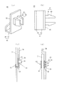
ところで、図5は、本発明者が、鏡をミラーキャビネット本体に取り付けるための固定部材の研究開発の過程において、工夫、検討してみた固定部材の一例の具体的な構成を示す図である。ここで、この図5に示す固定部材40(以下、「比較例」という)の構成について説明するが、鏡およびミラーキャビネット本体等の構成自体については、本発明に係るミラーキャビネットと変わらないので、本発明の実施例の全体構成を示す後記する図1を参照する。   By the way, FIG. 5 is a figure which shows the specific structure of an example of the fixing member which this inventor tried and devised in the process of research and development of the fixing member for attaching a mirror to a mirror cabinet main body. Here, the configuration of the fixing member 40 shown in FIG. 5 (hereinafter, referred to as “comparative example”) will be described, but the configuration itself of the mirror and the mirror cabinet main body is the same as the mirror cabinet according to the present invention. Reference is made to FIG. 1 to be described later showing the overall configuration of an embodiment of the present invention.

固定部材40は、ミラーキャビネット本体2に固定し、鏡3の下端を保持した状態として、鏡3をミラーキャビネット本体2に取り付けるものである。この固定部材40は、図5(a)〜(d)に示すように、鏡保持部41、背面部42および係止部43を備えている。鏡保持部41は、鏡3の下端部を受けて保持するための前面壁44および底面壁45を有し、側面視で略L字状に形成されている。   The fixing member 40 is fixed to the mirror cabinet body 2 and attaches the mirror 3 to the mirror cabinet body 2 with the lower end of the mirror 3 held. As shown in FIGS. 5A to 5D, the fixing member 40 includes a mirror holding portion 41, a back surface portion 42, and a locking portion 43. The mirror holding part 41 has a front wall 44 and a bottom wall 45 for receiving and holding the lower end of the mirror 3 and is formed in a substantially L shape in a side view.

背面部42は、鏡保持部41の底面壁45から起立するように形成されており、その後面から係止部43が後方に突出するように形成されている。係止部43は、軸部48と、軸部48の先端側に形成されたフック部49とから成るものが、左右一対、互いに間隔をおいて設けられて構成されている。軸部48は、その垂直断面が矩形であり、板状に形成されている。   The back surface portion 42 is formed so as to stand up from the bottom wall 45 of the mirror holding portion 41, and the locking portion 43 is formed so as to protrude rearward from the rear surface. The locking portion 43 is composed of a shaft portion 48 and a hook portion 49 formed on the tip end side of the shaft portion 48, and a pair of left and right portions are provided at intervals. The shaft 48 has a rectangular vertical cross section and is formed in a plate shape.

この固定部材40を使用して、鏡3をミラーキャビネット本体2に固定する構成は、次のとおりである。鏡3の下端は、鏡保持部41で下から受けて保持される。具体的には、鏡3の下端は、固定部材40の前面壁44と背面部42の間に挿入し挟持され底面壁45上に載置されて保持される。   The structure for fixing the mirror 3 to the mirror cabinet body 2 using the fixing member 40 is as follows. The lower end of the mirror 3 is received and held by the mirror holding portion 41 from below. Specifically, the lower end of the mirror 3 is inserted and sandwiched between the front wall 44 and the back surface portion 42 of the fixing member 40 and placed and held on the bottom wall 45.

固定部材40は、その係止部43は、ミラーキャビネット本体2に形成されている一対の矩形の係止孔50に挿入されて固定される。固定部材40は、このように固定された状態では、ミラーキャビネット本体2の段部53上に載置された状態となる。そして、固定部材40は、その係止部43のフック部49がミラーキャビネット本体2の後面に当接して係合するので、ミラーキャビネット本体2の係止孔50から前方に抜けない。   The locking member 43 of the fixing member 40 is inserted and fixed into a pair of rectangular locking holes 50 formed in the mirror cabinet body 2. When the fixing member 40 is fixed in this manner, the fixing member 40 is placed on the stepped portion 53 of the mirror cabinet body 2. And since the hook part 49 of the latching | locking part 43 contact | abuts and engages the rear surface of the mirror cabinet main body 2, the fixing member 40 does not come out from the latching hole 50 of the mirror cabinet main body 2 forward.

図5に示すような比較例の固定部材40は、その構造はシンプルであるが、本発明者は、その開発過程において、次のような問題があるという知見を得た。ミラーキャビネット本体2の係止孔50は、一対の矩形孔として形成されているが、このような矩形の係止孔50は、回転ドリルでは形成しにくく、専用の穿孔用工具や装置が必要であり、現場での作業がしにくい。   The fixing member 40 of the comparative example as shown in FIG. 5 has a simple structure, but the present inventor has obtained the knowledge that there is the following problem in the development process. The locking holes 50 of the mirror cabinet body 2 are formed as a pair of rectangular holes. However, such rectangular locking holes 50 are difficult to form with a rotary drill, and a dedicated drilling tool or device is required. Yes, it is difficult to work on site.

固定部材40の係止部43は、一対の軸部48を有するが、その断面形状は矩形であるから、その断面形状に応じて、一対の係止孔50は互いに所定の位置関係で、正確に形成する必要がある。係止孔50が傾いていたりして正確に形成されていないと、係止部43の挿入が困難となり、係止孔50に固定部材40の係止部43を挿入したつもりでも、不完全に挿入される場合があり、固定部材40がミラーキャビネット本体2から不用意に抜けて、鏡の落下の原因となる可能性がある。   The locking portion 43 of the fixing member 40 has a pair of shaft portions 48, and since the cross-sectional shape thereof is rectangular, the pair of locking holes 50 are accurately positioned in a predetermined positional relationship with each other according to the cross-sectional shape. Need to be formed. If the locking hole 50 is tilted or not formed accurately, it becomes difficult to insert the locking portion 43, and even if the locking portion 43 of the fixing member 40 is intended to be inserted into the locking hole 50, it is incomplete. In some cases, the fixing member 40 may be carelessly removed from the mirror cabinet body 2 and cause the mirror to fall.

また、固定部材40の係止部43の断面形状に応じて、係止孔50は正確に形成されていた場合であって、係止孔50に固定部材40の係止部43を挿入したつもりでも、係止部43を係止孔50に確実に挿入されていない状態とすると、固定部材40がミラーキャビネット本体2から抜けて、鏡3の落下の原因となる可能性がある。   In addition, the locking hole 50 is accurately formed according to the cross-sectional shape of the locking portion 43 of the fixing member 40, and the locking portion 43 of the fixing member 40 is inserted into the locking hole 50. However, if the locking portion 43 is not securely inserted into the locking hole 50, the fixing member 40 may come off the mirror cabinet body 2 and cause the mirror 3 to fall.

さらに、仮に係止孔50に固定部材40の係止部43を完全に挿入し係合させても、フック部49はその構造上、係止孔50の周囲に比較的少ない部分でしか係合できず、掛かりが少ないので、固定部材40の係止部43に作用する水平方向の引き抜き力に対する係合力が比較的弱く、不用意にはずれる可能性がある。   Further, even if the locking portion 43 of the fixing member 40 is completely inserted and engaged with the locking hole 50, the hook portion 49 is engaged with only a relatively small portion around the locking hole 50 due to its structure. The engagement force with respect to the horizontal pull-out force acting on the locking portion 43 of the fixing member 40 is relatively weak and may be inadvertently disengaged.

また、固定部材40に鏡の自重による鉛直方向の荷重がかかり、係止部43の変形や、ミラーキャビネット本体2の取り付け時のねじれ変形等により係止孔50が広がる変形が生じる場合がある。このような変形によって、係止孔50から固定部材40の係止部43がはずれることに対する安全策として、ミラーキャビネット本体2の段部53を形成し、ミラーキャビネット本体2を取り付けた際に、この段部53に固定部材40が載置された状態としている。   In addition, a vertical load due to the weight of the mirror is applied to the fixing member 40, and the locking hole 43 may be deformed, or the deformation of the locking hole 50 may be expanded due to torsional deformation when the mirror cabinet body 2 is attached. As a safety measure against the locking portion 43 of the fixing member 40 coming off from the locking hole 50 due to such deformation, the stepped portion 53 of the mirror cabinet body 2 is formed, and when the mirror cabinet body 2 is attached, The fixing member 40 is placed on the stepped portion 53.

しかし、このような段部53を予め形成することは、ミラーキャビネット本体2の構成を複雑とし、製造コストの点からみても好ましくはない。さらに、このような段部53を備えたミラーキャビネット本体2の場合は、長さが異なる鏡3の固定に対応できないという問題がある。   However, forming the stepped portion 53 in advance makes the configuration of the mirror cabinet body 2 complicated and is not preferable from the viewpoint of manufacturing cost. Furthermore, in the case of the mirror cabinet main body 2 provided with such a stepped portion 53, there is a problem that it is not possible to support the fixing of the mirrors 3 having different lengths.

本発明は、上記従来例問題を解決することを目的とし、また比較例の問題を解決することを目的とし、シンプルな構造で、係止孔に確実に固定部材を挿入して係合でき、しかも固定部材が係合状態から不用意に抜け出ることなく、確実に鏡をミラーキャビネット本体に固定することの可能な固定部材を備えたミラーキャビネットを実現することを課題とする。   The object of the present invention is to solve the above-described conventional example problem and to solve the problem of the comparative example, and with a simple structure, the fixing member can be reliably inserted into the engagement hole and engaged, Moreover, it is an object of the present invention to realize a mirror cabinet including a fixing member that can reliably fix the mirror to the mirror cabinet body without the fixing member being carelessly removed from the engaged state.

本発明は上記課題を解決するために、鏡と、ミラーキャビネット本体と、鏡をミラーキャビネット本体に固定するための固定部材と、を備えたミラーキャビネットであって、固定部材は、鏡を保持するための前面壁および底面壁を有し側面視で略L字状に形成された鏡保持部と、鏡保持部の底面壁から起立する背面部と、ミラーキャビネット本体に形成された係止孔に挿入され、平面視で矢尻状に形成された係止部と、を含んでおり、係止部は、軸部と軸部の先端から連続して形成された係止片とを有し、かつ背面部に形成された円形の台座部から突出するように形成されていることを特徴とするミラーキャビネットを提供する。   In order to solve the above-described problems, the present invention is a mirror cabinet including a mirror, a mirror cabinet body, and a fixing member for fixing the mirror to the mirror cabinet body, and the fixing member holds the mirror. A mirror holding portion having a front wall and a bottom wall for forming a substantially L-shape in a side view, a back portion rising from the bottom wall of the mirror holding portion, and a locking hole formed in the mirror cabinet body And an engaging part formed in an arrowhead shape in plan view, the engaging part having a shaft part and a locking piece formed continuously from the tip of the shaft part, and Provided is a mirror cabinet which is formed so as to protrude from a circular pedestal formed on a back surface.

台座部の厚みが、ミラーキャビネット本体の係止孔が開口される部位の厚みよりも大きい寸法に設定されていることが好ましい。   It is preferable that the thickness of the pedestal is set to be larger than the thickness of the portion where the locking hole of the mirror cabinet body is opened.

係止部は、軸部が薄板状に形成されており、 その主面が鏡保持部の底面壁と直交する向きに設けられていることが好ましい。   The locking portion preferably has a shaft portion formed in a thin plate shape, and a main surface thereof is provided in a direction orthogonal to the bottom wall of the mirror holding portion.

係止片と軸部との接合箇所の内面部が曲面とされていることが好ましい。   It is preferable that the inner surface portion of the joint portion between the locking piece and the shaft portion is a curved surface.

係止孔の外周部には、補強用の環状リブが、係止孔と同心円状に形成されていることが好ましい。   It is preferable that an annular rib for reinforcement is formed concentrically with the locking hole on the outer peripheral portion of the locking hole.

ミラーキャビネット本体の鏡が取り付けられる取り付け部は、長さの異なる複数の鏡が選択的に取り付け可能なように、段差のない平面として形成され、係止孔を開口可能な係止孔形成部が、取り付け部に対して上下方向の複数箇所に形成されていることが好ましい。   The attachment part to which the mirror of the mirror cabinet body is attached is formed as a flat surface without a step so that a plurality of mirrors having different lengths can be selectively attached. It is preferable that they are formed at a plurality of locations in the vertical direction with respect to the attachment portion.

本発明によれば、ミラーキャビネットは、円形台座部と、矢尻状の係止部とを備えた固定部材を、鏡の下面に対応する位置に形成された係止孔に挿入することにより、鏡をキャビネットに固定するものであるから、シンプルな構造で、確実に鏡を固定することが可能となる。   According to the present invention, the mirror cabinet includes a circular pedestal portion and an arrowhead-shaped locking portion inserted into a locking hole formed at a position corresponding to the lower surface of the mirror. Since the mirror is fixed to the cabinet, the mirror can be securely fixed with a simple structure.

本発明に係るミラーキャビネットの実施例を説明する図であり、(a)はミラーキャビネットの全体構成を示す斜視図であり、(b)は鏡の上端を保持するミラーキャビネット本体の固定片の構成を説明する垂直断面図である。It is a figure explaining the Example of the mirror cabinet which concerns on this invention, (a) is a perspective view which shows the whole structure of a mirror cabinet, (b) is a structure of the fixed piece of the mirror cabinet main body holding the upper end of a mirror FIG. 上記実施例における固定部材を説明する図であり、(a)、(b)は斜視図であり、(c)は平面図であり、(d)は正面図である。It is a figure explaining the fixing member in the said Example, (a), (b) is a perspective view, (c) is a top view, (d) is a front view. (a)、(b)は上記実施例におけるミラーキャビネット本体の補強用の環状リブおよび係止孔形成部を説明するための垂直断面図と正面図であり、(c)はミラーキャビネット本体への鏡の取付方を説明する図である。(A), (b) is the vertical sectional view and front view for demonstrating the annular rib for a reinforcement of the mirror cabinet main body in the said Example, and a locking hole formation part, (c) is a mirror cabinet main body. It is a figure explaining how to attach a mirror. 上記実施例において、鏡をミラーキャビネット本体に取り付けるために固定部材をミラーキャビネット本体に固定した状態を示す図であり、(a)は水平断面図であり、(b)は(a)のB−B断面図であり、(c)は別の態様の固定部材をミラーキャビネット本体に固定した状態を示す水平断面図である。In the said Example, it is a figure which shows the state which fixed the fixing member to the mirror cabinet main body in order to attach a mirror to a mirror cabinet main body, (a) is a horizontal sectional view, (b) is B- of (a). It is B sectional drawing, (c) is a horizontal sectional view which shows the state which fixed the fixing member of another aspect to the mirror cabinet main body. 比較例のミラーキャビネットにおける固定部材を説明する図であり、(a)は斜視図であり、(b)は平面図であり、(c)と(d)は鏡をミラーキャビネット本体に取り付けるために固定部材をミラーキャビネット本体に固定した状態を示す垂直断面図と水平断面図である。It is a figure explaining the fixing member in the mirror cabinet of a comparative example, (a) is a perspective view, (b) is a top view, (c) And (d) is for attaching a mirror to a mirror cabinet main body. It is the vertical sectional view and horizontal sectional view which show the state which fixed the fixing member to the mirror cabinet main body.

本発明に係るミラーキャビネットを実施するための形態を実施例に基づき図面を参照して、以下説明する。   EMBODIMENT OF THE INVENTION The form for implementing the mirror cabinet which concerns on this invention is demonstrated below with reference to drawings based on an Example.

(実施例)
本発明に係るミラーキャビネットの実施例を図1〜図4において説明する。本実施例では、ミラーキャビネットを正面から見て、左右を左右とし、手前側を前方とし、奥側を後方として説明する。
(Example)
An embodiment of a mirror cabinet according to the present invention will be described with reference to FIGS. In this embodiment, the mirror cabinet is viewed from the front, and the left and right are defined as left and right, the front side is defined as the front, and the back side is defined as the rear.

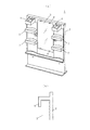
図1は、本発明に係るミラーキャビネット1の全体構成を示す。ミラーキャビネット1は、ミラーキャビネット本体2と、鏡3と、鏡3をミラーキャビネット本体2に固定するための固定部材6と、を備えている。   FIG. 1 shows the overall configuration of a mirror cabinet 1 according to the present invention. The mirror cabinet 1 includes a mirror cabinet main body 2, a mirror 3, and a fixing member 6 for fixing the mirror 3 to the mirror cabinet main body 2.

鏡3は、ミラーキャビネット本体2の前面中央に固定されており、鏡3の左右両側には、複数の収納棚7が取り付けられており、これらの収納棚7の上方には照明具8が設けられている。   The mirror 3 is fixed at the center of the front surface of the mirror cabinet body 2, and a plurality of storage shelves 7 are attached to the left and right sides of the mirror 3, and a lighting fixture 8 is provided above these storage shelves 7. It has been.

鏡3をミラーキャビネット本体2に固定する構造は、その上端を、図1(b)に示すように、ミラーキャビネット本体2の上部に一体で形成された略L字形の固定片9で保持し、下端をミラーキャビネット本体2に着脱可能に取り付ける固定部材6で受けて固定する構成である。   In the structure for fixing the mirror 3 to the mirror cabinet body 2, the upper end thereof is held by a substantially L-shaped fixing piece 9 formed integrally with the upper portion of the mirror cabinet body 2, as shown in FIG. The lower end is received and fixed by a fixing member 6 detachably attached to the mirror cabinet body 2.

なお、鏡2をミラーキャビネット本体2に固定する構成の別の態様として、上記構成とは逆に、鏡3の下端を、図示はしないが、ミラーキャビネット本体2の下端に一体で形成した略L字形の固定片で受けて保持し、上端をミラーキャビネット本体2に着脱可能に取り付ける固定部材で固定する構成としてもよい。   Note that, as another aspect of the configuration for fixing the mirror 2 to the mirror cabinet main body 2, contrary to the above configuration, the lower end of the mirror 3 is not illustrated, but is substantially L formed integrally with the lower end of the mirror cabinet main body 2. It is good also as a structure which receives and hold | maintains with a letter-shaped fixed piece, and fixes it by the fixing member attached to the mirror cabinet main body 2 so that attachment or detachment is possible.

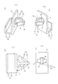
固定部材6は、樹脂(例えば、PP樹脂、ナイロン樹脂等)で形成され、図2(a)〜(d)に示すように、鏡保持部12、背面部13および係止部14を備えている。鏡保持部12は、鏡3の下端部を受けて保持するための前面壁17および底面壁18を有し、側面視で略L字状に形成されている。   The fixing member 6 is made of resin (for example, PP resin, nylon resin, etc.), and includes a mirror holding portion 12, a back surface portion 13, and a locking portion 14, as shown in FIGS. Yes. The mirror holding part 12 has a front wall 17 and a bottom wall 18 for receiving and holding the lower end of the mirror 3 and is formed in a substantially L shape in a side view.

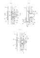
背面部13は、鏡保持部12の底面壁18から上方に起立するように形成されており、その後面に円形の台座部19が形成されている。台座部19は、ミラーキャビネット本体2に形成された円形の係止孔22にぴったりと嵌合する直径で形成されている。台座部19の厚みtは、図4(a)に示す例では、係止孔22におけるミラーキャビネット本体2の厚みt’より小さい。   The back surface portion 13 is formed so as to rise upward from the bottom wall 18 of the mirror holding portion 12, and a circular pedestal portion 19 is formed on the rear surface thereof. The pedestal 19 is formed with a diameter that fits snugly into a circular locking hole 22 formed in the mirror cabinet body 2. In the example shown in FIG. 4A, the thickness t of the pedestal portion 19 is smaller than the thickness t ′ of the mirror cabinet body 2 in the locking hole 22.

しかし、台座部19の厚みtは、図4(c)に示すように、係止孔22におけるミラーキャビネット本体2の厚みt’より大きくして、台座部19の後端が係止孔22から後方に突出し、ミラーキャビネット本体2の後面23よりさらに後方に位置するような構成としてもよい。   However, as shown in FIG. 4C, the thickness t of the pedestal portion 19 is larger than the thickness t ′ of the mirror cabinet body 2 in the locking hole 22, and the rear end of the pedestal portion 19 extends from the locking hole 22. It is good also as a structure which protrudes back and is located in the back further from the rear surface 23 of the mirror cabinet main body 2. FIG.

係止部14は、図2(a)〜(d)に示すように、背面部13の後面に形成された円形の台座部19から後方に突出するように形成されており、軸部24と、軸部24の先端(後端)から連続して形成された係止片25とを有する。係止片25は、図2(c)に示すように、平面視で矢尻状に形成されている。即ち、軸部24の先端から左右前方に向けて徐々広がるように、ハの字形に形成されている。   As shown in FIGS. 2A to 2D, the locking portion 14 is formed so as to protrude rearward from a circular pedestal portion 19 formed on the rear surface of the back surface portion 13. , And a locking piece 25 formed continuously from the front end (rear end) of the shaft portion 24. As shown in FIG. 2C, the locking piece 25 is formed in an arrowhead shape in a plan view. That is, it is formed in a square shape so as to gradually spread from the tip of the shaft portion 24 toward the left and right front.

固定部材6の軸部24は薄板状に形成されており、その主面(垂直面)26は、鏡保持部12の底面壁18と直交する向きに設けられている。そして、係止片25も薄板状に形成されており、軸部24と同様にその主面(垂直面)27は鏡保持部12の底面壁18と直交する向きに設けられている。   The shaft portion 24 of the fixing member 6 is formed in a thin plate shape, and its main surface (vertical surface) 26 is provided in a direction orthogonal to the bottom wall 18 of the mirror holding portion 12. The locking piece 25 is also formed in a thin plate shape, and its main surface (vertical surface) 27 is provided in a direction orthogonal to the bottom wall 18 of the mirror holding portion 12, similarly to the shaft portion 24.

係止部14は、ミラーキャビネット本体2に形成された係止孔22に挿入し係合することで、固定部材6をミラーキャビネット本体2に固定するものである。係止部14の軸部24と係止片25が係止孔22に挿入されると、係止片25がミラーキャビネット本体2の後面23に係合可能となり、抜け止めされる。   The locking part 14 fixes the fixing member 6 to the mirror cabinet body 2 by being inserted into and engaged with a locking hole 22 formed in the mirror cabinet body 2. When the shaft portion 24 and the locking piece 25 of the locking portion 14 are inserted into the locking hole 22, the locking piece 25 can be engaged with the rear surface 23 of the mirror cabinet body 2 and is prevented from coming off.

図2(c)に示すように、係止片25と軸部24との接合箇所の内面部31が曲面とされており(Rがつけられている)、これにより、係止片25と軸部24との接合箇所への、応力の集中を避けることができる。   As shown in FIG. 2 (c), the inner surface portion 31 of the joint portion between the locking piece 25 and the shaft portion 24 is a curved surface (R is attached), whereby the locking piece 25 and the shaft It is possible to avoid stress concentration at the joint with the portion 24.

係止孔22は、上記のとおり係止部14を挿入するものであり、円形の台座部19がぴったりと嵌合するように、垂直断面が円形に形成されている。そして、係止孔22は、ミラーキャビネット本体2において、固定部材6を取り付ける箇所に対応して、左右一対、形成される。ミラーキャビネット本体2の下部における係止孔22の形成箇所は、鏡3の長さに対応して、適宜調整される。   The locking hole 22 is for inserting the locking portion 14 as described above, and has a circular vertical cross section so that the circular pedestal portion 19 fits snugly. Then, a pair of locking holes 22 are formed on the mirror cabinet main body 2 corresponding to the location where the fixing member 6 is attached. The location where the locking hole 22 is formed in the lower part of the mirror cabinet body 2 is appropriately adjusted according to the length of the mirror 3.

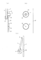
ミラーキャビネット本体2の鏡3が固定部材によって固定される取り付け部32は、図3(a)、(b)に示すが、長さの異なる複数の鏡3が選択的に取り付け可能なように、前面(表面)側が段差のない平面として形成されており、係止孔22を開口可能な係止孔形成部33が、取り付け部32に対して上下方向の複数箇所に形成されている。   Although the attachment part 32 to which the mirror 3 of the mirror cabinet main body 2 is fixed by a fixing member is shown in FIGS. 3A and 3B, a plurality of mirrors 3 having different lengths can be selectively attached. The front (front surface) side is formed as a flat surface without steps, and the locking hole forming portions 33 that can open the locking holes 22 are formed at a plurality of locations in the vertical direction with respect to the mounting portion 32.

ここで、係止孔形成部33は、具体的には、ドリルの先端を嵌合することの可能な位置決め用の凹部であり、取り付け部32における係止孔22の形成が予定される上下方向の複数の箇所に形成される。このような係止孔形成部33と、該係止孔形成部33と同心で断面凸状の補強用の環状リブ34を、ミラーキャビネット本体2の製造時に予め形成しておくと良い。   Here, the locking hole forming portion 33 is specifically a positioning concave portion into which the tip of the drill can be fitted, and the vertical direction in which the locking hole 22 in the mounting portion 32 is expected to be formed. Are formed at a plurality of locations. Such a locking hole forming portion 33 and a reinforcing annular rib 34 that is concentric with the locking hole forming portion 33 and has a convex cross section may be formed in advance when the mirror cabinet body 2 is manufactured.

係止孔形成部33を形成しておくと、鏡の長さに対応して、ドリルで係止孔22を形成する位置がすぐ分かり、ドリルの先端を嵌合させることができるので、係止孔22を形成する作業がし易くなる。   If the locking hole forming portion 33 is formed, the position where the locking hole 22 is formed by the drill can be immediately known and the tip of the drill can be fitted in accordance with the length of the mirror. The work of forming the holes 22 is facilitated.

また、係止孔形成部33の周囲に、補強用の環状リブ34を形成しておくと、当該係止孔形成部33を利用して係止孔22が形成された場合、その係止孔22に対して同心で環状リブ34が設けられているので、係止孔22およびその周囲の剛性を高めることができ、固定部材6を介して鏡3の重量による荷重がかかっても、係止孔22およびその周囲の変形等がしにくい構造となる。   Further, if a reinforcing annular rib 34 is formed around the locking hole forming portion 33, when the locking hole 22 is formed using the locking hole forming portion 33, the locking hole is formed. Since the annular rib 34 is provided concentrically with the locking hole 22, the rigidity of the locking hole 22 and its surroundings can be increased, and even when a load due to the weight of the mirror 3 is applied via the fixing member 6, The hole 22 and its surroundings are not easily deformed.

(作用)
上記構成から成る実施例のミラーキャビネット1の作用を、以下説明する。ミラーキャビネット本体2に鏡3を取り付ける作業に際しては、まず、鏡3の長さに対応して、固定部材6を固定するミラーキャビネット本体2における左右の固定位置を決める。そして、市販のドリル等を使用して、ミラーキャビネット本体2を貫通する円形の係止孔22を、固定部材6の台座部19が丁度嵌合する程度の直径となるように形成する。係止孔22は、成型時に金型等を利用して開口されるのでもよい。
(Function)
The operation of the mirror cabinet 1 of the embodiment having the above configuration will be described below. When attaching the mirror 3 to the mirror cabinet body 2, first, the left and right fixing positions in the mirror cabinet body 2 to which the fixing member 6 is fixed are determined according to the length of the mirror 3. Then, using a commercially available drill or the like, the circular locking hole 22 penetrating the mirror cabinet body 2 is formed so as to have a diameter enough to fit the pedestal 19 of the fixing member 6. The locking hole 22 may be opened using a mold or the like at the time of molding.

この場合、前記したとおり、ミラーキャビネット本体2の取り付け部32の上下方向の複数箇所に、予め、図3(a)、(b)に示すように、係止孔形成部33を形成しておくと、鏡3の長さに応じて、ミラーキャビネット本体2における固定部材6の固定位置を、選択的に位置決めすることが簡単となり、また、ドリル先端が滑ることがなくなるので、係止孔22の形成が簡単となる。   In this case, as described above, the locking hole forming portions 33 are formed in advance at a plurality of locations in the vertical direction of the mounting portion 32 of the mirror cabinet body 2 as shown in FIGS. According to the length of the mirror 3, the fixing position of the fixing member 6 in the mirror cabinet main body 2 can be easily and selectively positioned, and the drill tip does not slip. Formation is simple.

また、その係止孔形成部33を中心にした環状リブ34は、ミラーキャビネット本体2の後面23に形成されているので、意匠性(見た目)を悪くすることなく、固定部材6の台座部19を支持する係止孔22およびその周囲の剛性を高めることができる。   Further, since the annular rib 34 centered on the locking hole forming portion 33 is formed on the rear surface 23 of the mirror cabinet body 2, the pedestal portion 19 of the fixing member 6 is not deteriorated in design (appearance). It is possible to increase the rigidity of the locking hole 22 that supports and surroundings.

次に、図3(c)に示すように、取り付けるべき鏡3の上端をミラーキャビネット本体2の固定片9に下方から嵌合する。そして、鏡3の下側をミラーキャビネット本体2から離した状態にしておいて、鏡3の下端の左右に、固定部材6を嵌合させる。即ち、固定部材6の下端が、固定部材6の前面壁17と背面部13の間において底面壁18に当接するまで挿入されるように、固定部材6を嵌合させる。   Next, as shown in FIG. 3C, the upper end of the mirror 3 to be attached is fitted to the fixed piece 9 of the mirror cabinet body 2 from below. Then, with the lower side of the mirror 3 separated from the mirror cabinet body 2, the fixing members 6 are fitted to the left and right of the lower end of the mirror 3. That is, the fixing member 6 is fitted so that the lower end of the fixing member 6 is inserted between the front wall 17 and the back surface portion 13 of the fixing member 6 until it contacts the bottom wall 18.

このように固定部材6を下端に嵌合させた鏡3を、ミラーキャビネット本体2の固定片9を中心に、図3(c)の矢印に示すように、ミラーキャビネット本体2に近づくように回動して、固定部材6の係止部14を、ミラーキャビネット本体2の係止孔22に、突き通すようにして挿入する。この挿入作業においては、軸部24および係止片25を挿入し、円形の台座部19を係止孔22に嵌合させる。この軸部24および係止片25が係止孔22を通過する際、左右の係止片25は軸部24に当接するように閉じ、通過後は係止片25が広がる。   The mirror 3 having the fixing member 6 fitted to the lower end in this manner is rotated around the fixing piece 9 of the mirror cabinet body 2 so as to approach the mirror cabinet body 2 as shown by the arrow in FIG. By moving, the locking portion 14 of the fixing member 6 is inserted into the locking hole 22 of the mirror cabinet body 2 so as to penetrate. In this insertion operation, the shaft portion 24 and the locking piece 25 are inserted, and the circular pedestal portion 19 is fitted into the locking hole 22. When the shaft portion 24 and the locking piece 25 pass through the locking hole 22, the left and right locking pieces 25 are closed so as to contact the shaft portion 24, and after passing, the locking piece 25 expands.

これにより、図4(a)、(b)に示すように、背面部13はミラーキャビネット本体2の前面に当接し、係止片25がミラーキャビネット本体2の後面側に位置し、固定部材6はミラーキャビネット本体2に固定された状態となる。そして、鏡3は、ミラーキャビネット本体2の前面に固定される。   As a result, as shown in FIGS. 4A and 4B, the back surface portion 13 abuts on the front surface of the mirror cabinet body 2, the locking piece 25 is positioned on the rear surface side of the mirror cabinet body 2, and the fixing member 6. Is fixed to the mirror cabinet body 2. The mirror 3 is fixed to the front surface of the mirror cabinet body 2.

固定部材6は、その底面壁18が水平状態ではなく、円形の台座部19の軸心を中心として左右方向に傾いてミラーキャビネット本体2に取り付けられても、ミラーキャビネット本体2に固定された鏡3の重量によって、固定部材6は、その円形の台座部19がその軸心を中心にして円形の係止孔22内で回動する。   Even if the fixing member 6 is attached to the mirror cabinet body 2 while the bottom wall 18 is not horizontal and is tilted in the left-right direction around the axis of the circular pedestal 19, the fixed member 6 is a mirror fixed to the mirror cabinet body 2. With the weight of 3, the fixing member 6 has its circular pedestal portion 19 rotated within the circular locking hole 22 around its axis.

そのため、底面壁18は水平状態となり、鏡3を鉛直方向に対して傾くことなく正確に保持できる。従って、固定部材6を固定する作業は、底面壁18を水平状態に調整する等の手間をかけることがない。なお、固定部材6は、鏡3の重量によって上記のとおり回動後、底面壁18が水平状態となると、その後は回動するようなことはない。   Therefore, the bottom wall 18 is in a horizontal state, and the mirror 3 can be accurately held without being inclined with respect to the vertical direction. Therefore, the operation of fixing the fixing member 6 does not require time and effort such as adjusting the bottom wall 18 to a horizontal state. The fixing member 6 does not rotate after the bottom wall 18 is in a horizontal state after rotating as described above due to the weight of the mirror 3.

鏡3の重量による鉛直方向の荷重は、円形の台座部19を介して円形の係止孔22の下曲面37で受けるので、円形の台座部19および円形の係止孔22のいずれについても、応力が1箇所に集中しない。従って、円形の台座部19、および円形の係止孔22とその周囲のいずれについても、破損等がしにくい。   Since the vertical load due to the weight of the mirror 3 is received by the lower curved surface 37 of the circular locking hole 22 via the circular pedestal 19, the circular pedestal 19 and the circular locking hole 22 are both Stress is not concentrated in one place. Therefore, the circular pedestal 19 and the circular locking hole 22 and its surroundings are hardly damaged.

鏡3の重量による荷重が固定部材6の底面壁18にかかると、図4(b)に矢印で示すように、固定部材6には前方へ傾くようなモーメントMがかかる。このモーメントMは、底面壁18にはその前部が下方に傾くように、また背面部13にはミラーキャビネット本体2から離れて前側に傾くように作用する。そのため、モーメントMは、固定部材6が係止孔22から前方に抜ける方向に作用する。   When a load due to the weight of the mirror 3 is applied to the bottom wall 18 of the fixing member 6, a moment M is applied to the fixing member 6 so as to tilt forward as indicated by an arrow in FIG. This moment M acts on the bottom wall 18 so that the front part thereof is inclined downward, and on the rear part 13 so as to be inclined away from the mirror cabinet body 2 to the front side. For this reason, the moment M acts in the direction in which the fixing member 6 is pulled forward from the locking hole 22.

しかし、本発明では、モーメントMによって固定部材6が係止孔22から抜けようとする作用を受けても、係止片25がミラーキャビネット本体2の後面23に当接し、広がるようにして係合するので、固定部材6が係止孔22から抜けるようなことは防止される。そのため、図5に示す比較例の固定部材40に比べて、固定部材6および鏡3を確実にミラーキャビネット本体2に固定できる。   However, in the present invention, even when the fixing member 6 is subjected to the action of trying to come out of the locking hole 22 due to the moment M, the locking piece 25 is brought into contact with the rear surface 23 of the mirror cabinet body 2 so as to expand. Therefore, the fixing member 6 is prevented from coming off from the locking hole 22. Therefore, the fixing member 6 and the mirror 3 can be reliably fixed to the mirror cabinet body 2 as compared with the fixing member 40 of the comparative example shown in FIG.

このように、鏡3が固定部材6で保持されている状態では、前記のとおり底面壁18は水平となるので、底面壁18に対して主面が直交する係止片25は、左右の係止片25がミラーキャビネット本体2の後面23に略均等に当接するので、抜けを阻止する力が強く、また係止片25の疲労も左右のいずれかに偏るようなことがない。   Thus, in the state where the mirror 3 is held by the fixing member 6, the bottom wall 18 is horizontal as described above. Therefore, the locking piece 25 whose main surface is orthogonal to the bottom wall 18 has the left and right engagements. Since the stop piece 25 abuts the rear surface 23 of the mirror cabinet body 2 substantially evenly, the force for preventing the release is strong, and the fatigue of the locking piece 25 is not biased to the left or right.

左右の係止片25は、通常は図4(a)に示すような状態にあるが、固定部材6が係止孔22から抜けるような力が作用すると、係止孔22は、ミラーキャビネット本体2の後面23に押しつけられた開き確実に係合される。このように係止片25が開閉する際に、係止片25と軸部24との接合箇所の内面部31へ応力がかかるが、この内面部31が曲面に形成されているので、応力の集中が軽減され、破損しにくい。   The left and right locking pieces 25 are normally in a state as shown in FIG. 4A, but when a force that causes the fixing member 6 to come out of the locking holes 22 is applied, the locking holes 22 2 is firmly engaged with the rear surface 23 of the opening. As described above, when the locking piece 25 is opened and closed, stress is applied to the inner surface portion 31 of the joint portion between the locking piece 25 and the shaft portion 24. However, since the inner surface portion 31 is formed in a curved surface, Concentration is reduced and it is hard to break.

また、固定部材6の軸部24および係止片25は、円形の台座部19から突出して形成されているので、固定部材6を係止孔22に挿入して固定する際に、不完全状態に固定することが回避できる。即ち、固定部材6を係止孔22に挿入する際に、円形の台座部19を係止孔22に正確に嵌合させないと、軸部24および係止片25は、係止孔22に挿入できず、仮に挿入されたとしても、係止片25の全体がミラーキャビネット本体2の後面23側に位置するまで挿入できない。   Further, since the shaft portion 24 and the locking piece 25 of the fixing member 6 are formed so as to protrude from the circular pedestal portion 19, when the fixing member 6 is inserted into the locking hole 22 and fixed, it is in an incomplete state. Can be avoided. That is, when the fixing member 6 is inserted into the locking hole 22, the shaft portion 24 and the locking piece 25 are inserted into the locking hole 22 unless the circular pedestal 19 is accurately fitted into the locking hole 22. Even if it is inserted, it cannot be inserted until the entire locking piece 25 is located on the rear surface 23 side of the mirror cabinet body 2.

従って、係止片25全体がミラーキャビネット本体2の後面23側の位置まで達していないような、固定部材6の不完全な状態での固定を防止できる。この結果、固定部材6が係止孔22に不完全な状態で固定されている場合に生じ易い、固定部材6が係止孔22から不用意に抜けて、鏡3が落下してしまうような事故を防止できる。   Therefore, the fixing member 6 can be prevented from being fixed in an incomplete state such that the entire locking piece 25 does not reach the position on the rear surface 23 side of the mirror cabinet body 2. As a result, it is likely to occur when the fixing member 6 is fixed to the locking hole 22 in an incomplete state, and the fixing member 6 is carelessly removed from the locking hole 22 and the mirror 3 falls. Accidents can be prevented.

図5に示す比較例の固定部材40に対する係止孔50は、一対の矩形の孔であり、その加工のために専用の穿孔用工具や装置が必要である。しかも、一対の矩形の孔の互いの位置関係を含めて所定の位置に精度良く形成する必要がある。しかし、本発明の固定部材6に対する係止孔22は、その断面が円形であるから、市販のドリルを利用して簡単に形成可能であり、また1つの円形の孔であるから、一対の矩形の孔から成る比較例の係止孔50に比べて、精度はそれほどは必要ない。   The locking hole 50 for the fixing member 40 of the comparative example shown in FIG. 5 is a pair of rectangular holes, and a dedicated drilling tool or device is required for the processing. In addition, it is necessary to accurately form a predetermined position including the positional relationship between the pair of rectangular holes. However, since the locking hole 22 for the fixing member 6 of the present invention has a circular cross section, it can be easily formed using a commercially available drill, and since it is a single circular hole, a pair of rectangular holes Compared with the locking hole 50 of the comparative example consisting of these holes, the accuracy is not so high.

なお、固定部材6をミラーキャビネット本体2の下端部に取り付けてから固定部材6をミラーキャビネット本体2に固定するのではなく、固定部材6をミラーキャビネット本体2に固定してから、鏡3の上端をミラーキャビネット本体2の固定片9に下方から嵌合し、鏡3の下端を固定部材6の鏡保持部12に載置して取り付けるようにしてもよい。   The fixing member 6 is not fixed to the mirror cabinet main body 2 after the fixing member 6 is attached to the lower end of the mirror cabinet main body 2, but the upper end of the mirror 3 is fixed after the fixing member 6 is fixed to the mirror cabinet main body 2. May be fitted to the fixed piece 9 of the mirror cabinet body 2 from below, and the lower end of the mirror 3 may be mounted on the mirror holding portion 12 of the fixed member 6.

ところで、台座部19の厚みtが、係止孔22におけるミラーキャビネット本体2の厚みt’より大きい場合は、固定部材6を係止孔22に取り付けると、図4(c)に示すように、台座部19の後端は、係止孔22から後方に突出し、ミラーキャビネット本体2の後面23よりさらに後方に位置するような状態となる。   By the way, when the thickness t of the pedestal 19 is larger than the thickness t ′ of the mirror cabinet body 2 in the locking hole 22, when the fixing member 6 is attached to the locking hole 22, as shown in FIG. The rear end of the pedestal 19 protrudes rearward from the locking hole 22 and is in a state of being positioned further rearward than the rear surface 23 of the mirror cabinet body 2.

このように台座部19の厚みが、係止孔22におけるミラーキャビネット本体2の厚みより大きい場合は、台座部19は、係止孔22の前後方向の全てにわたって係止孔22の内面に当接し支持される。従って、鏡3の重量による鉛直方向の荷重を、より広い面積の曲面で受けて確実に支持することができる。   As described above, when the thickness of the pedestal portion 19 is larger than the thickness of the mirror cabinet body 2 in the locking hole 22, the pedestal portion 19 abuts against the inner surface of the locking hole 22 over the entire front and rear direction of the locking hole 22. Supported. Therefore, the load in the vertical direction due to the weight of the mirror 3 can be received by the curved surface having a larger area and reliably supported.

また、前記したとおり、固定部材6の円形の台座部19が円形の係止孔22に確実に嵌合されない状態では、係止部14は係止孔22に挿入できない。従って、円形の台座部19は、係止部14が確実に係止孔22に挿入され、固定部材6が確実にミラーキャビネット本体2に固定されているか否かのチェック機能を発揮することができる。特に円形の台座部19の厚みtが長いと、係止孔22に嵌合し当接する部分が多くなるので、上記チェックをより確実に行うことが可能となる。   Further, as described above, the locking portion 14 cannot be inserted into the locking hole 22 when the circular pedestal portion 19 of the fixing member 6 is not securely fitted into the circular locking hole 22. Therefore, the circular pedestal portion 19 can exhibit a check function as to whether or not the locking portion 14 is reliably inserted into the locking hole 22 and the fixing member 6 is securely fixed to the mirror cabinet body 2. . In particular, when the thickness t of the circular pedestal portion 19 is long, the number of portions that fit into and come into contact with the locking holes 22 increases, so that the above check can be performed more reliably.

なお、図5に示す比較例の固定部材40は、鏡3を受け入れて支持している状態では、ミラーキャビネット本体2の段部53上に載置された状態となる。しかし、本発明の固定部材6は、このような段部53上に載置する構成ではないので、ミラーキャビネット本体2に、段部53等を形成する必要はない。   Note that the fixing member 40 of the comparative example shown in FIG. 5 is placed on the stepped portion 53 of the mirror cabinet body 2 in a state where the mirror 3 is received and supported. However, since the fixing member 6 of the present invention is not configured to be placed on such a stepped portion 53, it is not necessary to form the stepped portion 53 or the like in the mirror cabinet body 2.

以上、本発明に係るミラーキャビネットを実施するための形態を実施例に基づいて説明したが、本発明はこのような実施例に限定されるものではなく、特許請求の範囲に記載された技術的事項の範囲内でいろいろな実施例があることは言うまでもない。   As mentioned above, although the form for implementing the mirror cabinet based on this invention was demonstrated based on the Example, this invention is not limited to such an Example, The technical scope described in the claim It goes without saying that there are various embodiments within the scope of the matter.

本発明に係るミラーキャビネットは上記のような構成であるから、その固定部材による鏡のミラーキャビネットへの取付構造は、ミラーキャビネット以外のミラーの取付対象、例えば、浴室やリビング等の室内壁であっても適用可能である。   Since the mirror cabinet according to the present invention has the above-described configuration, the mounting structure of the mirror to the mirror cabinet by the fixing member is a mounting object of a mirror other than the mirror cabinet, for example, an indoor wall of a bathroom or a living room. Is applicable.

1 ミラーキャビネット
2 ミラーキャビネット本体
3 鏡
6 固定部材
7 収納棚
8 照明具
9 ミラーキャビネット本体の上部の固定片
12 固定部材の鏡保持部
13 固定部材の背面部
14 固定部材の係止部
17 鏡保持部の前面壁
18 鏡保持部の底面壁
19 固定部材の台座部
22 ミラーキャビネット本体の係止孔
23 ミラーキャビネット本体の後面
24 係止部の軸部
25 係止部の係止片
26 軸部の主面
27 係止片の主面
31 係止片と軸部の接合箇所の内面部
32 ミラーキャビネット本体における鏡の取り付け部
33 係止孔形成部
34 補強用の環状リブ
37 係止孔の下曲面
38 ミラーキャビネット本体
40 固定部材
41 固定部材の鏡保持部
42 固定部材の背面部
43 固定部材の係止部
44 鏡保持部の前面壁
45 鏡保持部の底面壁
48 係止部の軸部
49 係止部のフック部
50 係止孔
53 ミラーキャビネット本体の段部
1 Mirror cabinet
2 Mirror cabinet body
3 mirrors
6 Fixing member
7 Storage shelf
8 Lighting equipment
9 Fixed piece on the top of the mirror cabinet
12 Mirror holding part of fixed member
13 Back part of fixing member
14 Locking part of fixing member
17 Front wall of mirror holder
18 Bottom wall of mirror holder
19 Base of fixed member
22 Mirror cabinet body locking hole
23 Rear side of mirror cabinet
24 Shaft part of locking part
25 Locking piece of locking part
26 Main surface of shaft
27 Main surface of locking piece
31 Inner surface portion of the joint between the locking piece and the shaft portion
32 Mirror mount in the mirror cabinet
33 Locking hole forming part
34 Annular ribs for reinforcement
37 Lower curved surface of the locking hole
38 Mirror cabinet body
40 Fixing member
41 Mirror holding part of fixed member
42 Rear surface of the fixing member
43 Locking part of fixing member
44 Front wall of mirror holder
45 Bottom wall of mirror holder
48 Locking shaft
49 Hook of the locking part
50 Locking hole
53 Step of mirror cabinet

Claims (6)

鏡と、ミラーキャビネット本体と、鏡をミラーキャビネット本体に固定するための固定部材と、を備えたミラーキャビネットであって、固定部材は、鏡を保持するための前面壁および底面壁を有し側面視で略L字状に形成された鏡保持部と、鏡保持部の底面壁から起立する背面部と、ミラーキャビネット本体に形成された係止孔に挿入され、平面視で矢尻状に形成された係止部と、を含んでおり、係止部は、軸部と軸部の先端から連続して形成された係止片とを有し、かつ背面部に形成された円形の台座部から突出するように形成されていることを特徴とするミラーキャビネット。   A mirror cabinet comprising a mirror, a mirror cabinet body, and a fixing member for fixing the mirror to the mirror cabinet body, the fixing member having a front wall and a bottom wall for holding the mirror, and a side surface It is inserted into a mirror holding part formed in a substantially L shape in view, a back part rising from the bottom wall of the mirror holding part, and a locking hole formed in the mirror cabinet body, and formed in an arrowhead shape in plan view The locking portion includes a shaft portion and a locking piece formed continuously from the tip of the shaft portion, and from a circular pedestal portion formed on the back surface portion. A mirror cabinet characterized by being formed to protrude. 台座部の厚みが、ミラーキャビネット本体の係止孔が開口される部位の厚みよりも大きい寸法に設定されていることを特徴とする請求項1に記載のミラーキャビネット。   The mirror cabinet according to claim 1, wherein the thickness of the pedestal is set to be larger than the thickness of the portion where the locking hole of the mirror cabinet body is opened. 係止部は、軸部が薄板状に形成されており、 その主面が鏡保持部の底面壁と直交する向きに設けられていることを特徴とする請求項1または2に記載のミラーキャビネット。   3. The mirror cabinet according to claim 1, wherein the locking portion has a shaft portion formed in a thin plate shape, and a main surface thereof is provided in a direction orthogonal to the bottom wall of the mirror holding portion. . 係止片と軸部との接合箇所の内面部が曲面とされていることを特徴とする請求項1から3のいずれか1項に記載のミラーキャビネット。 The mirror cabinet according to any one of claims 1 to 3, wherein an inner surface portion of a joint portion between the locking piece and the shaft portion is a curved surface. 係止孔の外周部には、補強用の環状リブが、係止孔と同心円状に形成されていることを特徴とする請求項1から4のいずれか1項に記載のミラーキャビネット。   5. The mirror cabinet according to claim 1, wherein a reinforcing annular rib is formed concentrically with the locking hole on an outer peripheral portion of the locking hole. ミラーキャビネット本体の鏡が取り付けられる取り付け部は、長さの異なる複数の鏡が選択的に取り付け可能なように、段差のない平面として形成され、係止孔を開口可能な係止孔形成部が、取り付け部に対して上下方向の複数箇所に形成されていることを特徴とする請求項1から5のいずれか1項に記載のミラーキャビネット。   The attachment part to which the mirror of the mirror cabinet body is attached is formed as a flat surface without a step so that a plurality of mirrors having different lengths can be selectively attached. The mirror cabinet according to claim 1, wherein the mirror cabinet is formed at a plurality of locations in the vertical direction with respect to the mounting portion.
JP2013211656A 2013-10-09 2013-10-09 Mirror cabinet Pending JP2015073723A (en)

Priority Applications (1)

Application Number Priority Date Filing Date Title
JP2013211656A JP2015073723A (en) 2013-10-09 2013-10-09 Mirror cabinet

Applications Claiming Priority (1)

Application Number Priority Date Filing Date Title
JP2013211656A JP2015073723A (en) 2013-10-09 2013-10-09 Mirror cabinet

Publications (1)

Publication Number Publication Date
JP2015073723A true JP2015073723A (en) 2015-04-20

Family

ID=52999052

Family Applications (1)

Application Number Title Priority Date Filing Date
JP2013211656A Pending JP2015073723A (en) 2013-10-09 2013-10-09 Mirror cabinet

Country Status (1)

Country Link
JP (1) JP2015073723A (en)

Citations (8)

* Cited by examiner, † Cited by third party
Publication number Priority date Publication date Assignee Title
US4396249A (en) * 1981-07-06 1983-08-02 Jensen General Corp. Adjustable mounting support for mirrors
JPH11131755A (en) * 1997-10-31 1999-05-18 Takiron Co Ltd Edge finish structure of double floor of bathroom
JP2004242917A (en) * 2003-02-14 2004-09-02 Inax Corp Cabinet
JP2005240512A (en) * 2004-02-27 2005-09-08 Toto Ltd Bathroom floor pedestal
JP2007120679A (en) * 2005-10-28 2007-05-17 Sun Wave Ind Co Ltd Plate material joint structure
JP2010022427A (en) * 2008-07-15 2010-02-04 Koizumi Furnitech Corp System desk
JP2010104442A (en) * 2008-10-28 2010-05-13 Panasonic Electric Works Co Ltd Mirror attaching structure for mirror cabinet
JP2012120732A (en) * 2010-12-09 2012-06-28 Okamura Corp Desk apparatus

Patent Citations (8)

* Cited by examiner, † Cited by third party
Publication number Priority date Publication date Assignee Title
US4396249A (en) * 1981-07-06 1983-08-02 Jensen General Corp. Adjustable mounting support for mirrors
JPH11131755A (en) * 1997-10-31 1999-05-18 Takiron Co Ltd Edge finish structure of double floor of bathroom
JP2004242917A (en) * 2003-02-14 2004-09-02 Inax Corp Cabinet
JP2005240512A (en) * 2004-02-27 2005-09-08 Toto Ltd Bathroom floor pedestal
JP2007120679A (en) * 2005-10-28 2007-05-17 Sun Wave Ind Co Ltd Plate material joint structure
JP2010022427A (en) * 2008-07-15 2010-02-04 Koizumi Furnitech Corp System desk
JP2010104442A (en) * 2008-10-28 2010-05-13 Panasonic Electric Works Co Ltd Mirror attaching structure for mirror cabinet
JP2012120732A (en) * 2010-12-09 2012-06-28 Okamura Corp Desk apparatus

Similar Documents

Publication Publication Date Title
EP2861386B1 (en) Holding device with a stem part including a fin
EP3287712B1 (en) Attachment structure for water heater
CN102089535A (en) Connecting component for attaching an add-on part to a supporting part
JP4819111B2 (en) Frame mounting structure for fire fighting equipment storage box
JP4520920B2 (en) clip
JP2015073723A (en) Mirror cabinet
JP2020032012A (en) Wall-mounting member
JP6261743B2 (en) Latch
JP5142876B2 (en) Article mounting structure
JP3216777U (en) Optional member mounting structure
JP2016084869A (en) Item supporting jig
JP5265802B1 (en) Fixture
JP7745218B2 (en) Mounting device and display unit
KR101565145B1 (en) Hanger combined frame
JP2006223421A (en) Suspending tool
JP2011019171A (en) Temporary fixation structure of speaker holder
JP6714124B1 (en) Shelf holder
JP2011040024A (en) Article mounting implement
JP5275873B2 (en) Eaves hanger
JP5106466B2 (en) LOCKING TOOL, LOCKING STRUCTURE USING LOCKING TOOL, AND CONTAINER USING LOCKING TOOL
WO2010150855A1 (en) Fixture
JP2018138074A (en) Suspension device
JP2017101385A (en) Support structure of the frame
JP6761360B2 (en) Shower hook mounting aid
JP6625415B2 (en) Frame fixed structure

Legal Events

Date Code Title Description
A621 Written request for application examination

Free format text: JAPANESE INTERMEDIATE CODE: A621

Effective date: 20160927

A977 Report on retrieval

Free format text: JAPANESE INTERMEDIATE CODE: A971007

Effective date: 20170531

A131 Notification of reasons for refusal

Free format text: JAPANESE INTERMEDIATE CODE: A131

Effective date: 20170620

A02 Decision of refusal

Free format text: JAPANESE INTERMEDIATE CODE: A02

Effective date: 20180109