JP2015073722A - Arm swing correcting tool - Google Patents
Arm swing correcting tool Download PDFInfo
- Publication number
- JP2015073722A JP2015073722A JP2013211652A JP2013211652A JP2015073722A JP 2015073722 A JP2015073722 A JP 2015073722A JP 2013211652 A JP2013211652 A JP 2013211652A JP 2013211652 A JP2013211652 A JP 2013211652A JP 2015073722 A JP2015073722 A JP 2015073722A
- Authority
- JP
- Japan
- Prior art keywords
- arm
- arm swing
- walking
- swinging
- connecting rod
- Prior art date
- Legal status (The legal status is an assumption and is not a legal conclusion. Google has not performed a legal analysis and makes no representation as to the accuracy of the status listed.)
- Granted
Links
- 230000000694 effects Effects 0.000 description 9
- 230000032683 aging Effects 0.000 description 5
- 238000005452 bending Methods 0.000 description 2
- 238000010586 diagram Methods 0.000 description 2
- 238000000034 method Methods 0.000 description 2
- 210000003205 muscle Anatomy 0.000 description 2
- 230000003247 decreasing effect Effects 0.000 description 1
- 230000005021 gait Effects 0.000 description 1
- 210000004705 lumbosacral region Anatomy 0.000 description 1
- 210000000323 shoulder joint Anatomy 0.000 description 1
Images
Landscapes
- Rehabilitation Tools (AREA)
Abstract
Description
本発明は、ウォーキング等の歩行時において右手と左手に1つずつ持って歩行するための器具であって、歩行時の腕振りによって生じる遠心力を利用することにより、歩行者がバランス良く前後に腕振りを行いつつ、意識せずとも、自然に正しい歩き方に矯正することを目的とする歩行時における腕振り矯正具である。 The present invention is a device for walking with one right hand and one left hand during walking such as walking, and by using the centrifugal force generated by arm swing during walking, the pedestrian can move back and forth in a balanced manner. This is an arm swing correction tool for walking aiming to correct the natural way of walking without consciousness while performing arm swing.
最近は健康ブームであり、特に中高年者の健康に対する関心が高く、手軽で身近な運動としてウォーキング等が盛んに行われている。ウォーキングをする人の中には体力(特に腕力)を増強する目的でアレー状の器具を持ちながらウォーキングすることにより筋力アップを図ろうとする人もいる。 Recently, there has been a health boom, especially for middle-aged and elderly people who are highly interested in health, and walking and other activities are actively performed as an easy and familiar exercise. Some people who walk are trying to gain strength by walking while holding an array of instruments to increase physical strength (especially arm strength).
ウォーキングは手軽に行える運動として健康の維持には最適であるといえるものの、正しい歩き方をしていないとその効果は半減する。健康を維持する正しい歩行をするためには正しい腕振りをすることが肝要である。確かに歩行は主として脚の運動であり、腕振りは歩行に関しては補助的な運動でしか無いとも考えられる。 Walking is an easy exercise that can be said to be optimal for maintaining your health, but if you don't walk correctly, its effect is halved. It is important to swing the right arm in order to walk properly to maintain health. Certainly, walking is mainly a movement of the legs, and arm swinging can only be an auxiliary movement for walking.
しかしながら、歩行時の腕振りに伴う上半身(両肩部)の捻転運動は、脚の蹴り出し及び下半身(腰部)の捻転運動とのバランスを取り、しかも腕振りの方向や強弱により歩行運動全体をコントロールするという重要な役割を果たしている。即ち、健康を維持するような正しい歩行をするためには、まずは正しい腕振りが不可欠であるといえる。バランスよく前後に腕を振って歩くことが歩行の基本中の基本であると言える。 However, the torsional motion of the upper body (both shoulders) associated with arm swing during walking balances the kicking out of the legs and the torsional motion of the lower body (waist), and the entire walking motion is controlled by the direction and strength of arm swinging. It plays an important role of controlling. In other words, it can be said that proper arm swinging is indispensable in order to walk properly to maintain health. It can be said that walking in a well-balanced manner with the arms back and forth is the basic of walking.
最近では、特許文献1の如く、握り部と平板状のバランス部とを連結ロッドを介して連結した構成を有する用具で平板状のバランス部の表裏面に空気抵抗を生じさせることにより、歩行のバランスを良くする作用効果を発揮する器具が知られている。この器具は、歩行を積極的に補助するものでも、筋力を増強するものでもなく、散歩時に使用して快適な歩行を促す目的の歩行補助具(特許文献1 要約参照)である。 Recently, as shown in Patent Document 1, by using a tool having a structure in which a grip portion and a flat balance portion are connected via a connecting rod, air resistance is generated on the front and back surfaces of the flat balance portion, thereby allowing walking. Devices that exhibit the effect of improving the balance are known. This device is neither a device that actively assists walking nor a device that reinforces muscle strength, and is a walking assist device that is intended to be used during a walk to promote comfortable walking (see the abstract of Patent Document 1).
しかしながら、特許文献1に係る歩行補助具は、補助具を持つことで、歩行時の腕振りの意識が高まり歩行のバランスを良くする効果があるとのことであるが、歩行時の腕振りの意識が高まっただけで何らかの矯正力が働かなければ正しい腕振りをすることはできないし、正しい歩き方をすることもできない。即ち、特許文献1に係る歩行補助具では、歩行者が正しい腕振りをすることにより自然に正しい歩き方を身に着けることは困難であると考えられる。 However, the walking assist tool according to Patent Document 1 has the effect of improving the balance of walking by increasing the awareness of swinging the arm by having the assisting tool. You can't do the right arm swing, and you can't walk the right way if you don't have any corrective power. That is, with the walking aid according to Patent Document 1, it is considered difficult for a pedestrian to naturally wear the correct way of walking by swinging the correct arm.
本発明の目的は、歩行時の腕振りによって生じる遠心力を利用して、歩行者が正しい腕振りをすることにより、自然に正しい歩き方を身に着けることを目的とする腕振り矯正具を提供することにある。 An object of the present invention is to provide an arm swing correction tool intended to wear a correct way of walking naturally by a pedestrian performing correct arm swing using centrifugal force generated by arm swing during walking. It is to provide.
上記課題を解決するために、本願請求項1に記載した発明は、右手と左手に1つずつ握って歩行するための器具であって、右手又は左手で握るための握り部と、前記握り部の反対側に設置された重量部と、前記握り部と前記重量部との間を繋いでおり、略中心部もしくは略中心部よりも握り部側の部位において角度調整機能を有する連結ロッドとからなる腕振り矯正具であることを特徴とするものである。 In order to solve the above-mentioned problems, the invention described in claim 1 of the present application is an instrument for walking while gripping one by one in the right hand and the left hand, the grip part for gripping with the right hand or the left hand, and the grip part And a connecting rod having an angle adjusting function in a part near the grip part rather than the center part or the center part, connecting the weight part installed on the opposite side to the grip part and the weight part. It is the arm swing correction tool which becomes.
本願請求項2に記載した発明は、連結ロッドは、長さ調整機能を備えることを特徴とする請求項1に記載の腕振り矯正具であることを特徴とするものである。 The invention described in claim 2 of the present application is the arm swing correction tool according to claim 1, wherein the connecting rod has a length adjusting function.
本願請求項3に記載した発明は、重量部又は連結ロッドは、重量部の最大断面積よりも面積の広い平板を備えていることを特徴とする腕振り矯正具であることを特徴とするものである。 The invention described in claim 3 is an arm swing correction tool characterized in that the weight part or the connecting rod includes a flat plate having a larger area than the maximum cross-sectional area of the weight part. It is.
昔からずっと言われ続けているように、両腕を進行方向に向かって前後にバランス良く、大きく振って歩くということは、歩行の基本中の基本である。本願請求項1に係る腕振り矯正具は、連結ロッドを介して握り部の反対側に重量部が設置されているため、歩行時において重量部は、腕振り矯正具の先端(すなわち遠心力が最も大きく働く位置)に位置することになる。重量部にはある程度の重量があることにより、腕振り時に遠心力が発生する。 As has been said for a long time, walking with a good balance of both arms in the forward and backward direction toward the direction of travel is a fundamental aspect of walking. In the arm swing correction tool according to the first aspect of the present invention, since the weight part is installed on the opposite side of the grip part via the connecting rod, the weight part is the tip of the arm swing correction tool during walking (that is, the centrifugal force is reduced). The position that works the most). Since the weight part has a certain amount of weight, a centrifugal force is generated when the arm is swung.
かかる遠心力により増強された腕振りによって、上半身(肩部)の捻転運動が増強され、増強された上半身(肩部)の捻転運動とのバランスを取るために、脚の蹴り出し及び下半身(腰部)の捻転運動も意識せずとも自然に増強された腕振りに引きずられて増強される。これによって体全体を大きく動かすことができ、結果として正しい歩行動作が自然とできるようになる。 The arm swinging enhanced by the centrifugal force enhances the torsional motion of the upper body (shoulder), and in order to balance the increased torsional motion of the upper body (shoulder), kicking out the legs and lower body (waist) The torsional movement of) is strengthened by being dragged by a naturally enhanced arm swing without being aware of it. As a result, the entire body can be moved greatly, and as a result, a correct walking motion can be naturally performed.
本願請求項2に係る腕振り矯正具は、連結ロッドが角度調整機能を有しているため、使用者の好み及び目的に合わせて連結ロッドの角度を調整することで、遠心力の働く領域を自由に調整することができる。 Since the connecting rod has an angle adjusting function in the arm swing correction tool according to claim 2 of the present application, by adjusting the angle of the connecting rod according to the user's preference and purpose, the region where the centrifugal force works can be obtained. It can be adjusted freely.
人間は前後に腕振りをする時、肩関節の構造上の理由により、真横から見ると後方向に腕を振る時の振り幅よりも前方向に振る時の振り幅の方が大きくなる傾向がある。簡単に言うと前方向への腕振りの方が、後方向への腕振りよりも容易であるということである。この傾向は加齢とともに顕著に見られるようになる。一般的に、加齢によって起こりやすい老人性の歩行の特徴として、腕振りが乏しいといったものが挙げられるのであるが、加齢に伴って、後ろ方向に腕を振る時の振り幅が小さくなり、これに合わせて前に振る時の振り幅も小さくなると考えられる。 When swinging arms back and forth, humans tend to have larger swing widths when swinging forward than when swinging arms backwards, because of the structure of the shoulder joints. is there. Simply put, swinging the arm forward is easier than swinging the arm backward. This tendency becomes prominent with aging. In general, senile gait that tends to occur with aging is characterized by poor swinging of the arm, but with aging, the swing width when swinging the arm backwards becomes smaller, In accordance with this, the swing width when swinging forward is also considered to be small.
後ろに腕を振る時の振り幅が小さくなった結果、中高齢者が、腕を大きく振ろうと意識して一生懸命に歩くと、前方にばかり腕を振り上げて、後方へ振れていないという現象が起こり、前後にバランス良く腕を振るという歩行の理想形からはかけ離れた状態になってしまう。即ち、前方にばかり腕を振り上げて歩く人は、上半身が反り返って、脚を後ろへ蹴り出せない変な歩き方になってしまい好ましくない。 As a result of the swing width when swinging the arm backwards, when a middle-aged person walks hard with the intention of swinging the arm greatly, the arm swings up just forward and does not swing backward It happens, and it will be in a state far from the ideal form of walking where the arm is shaken in a well-balanced manner. That is, a person who walks with his arms raised only forward is not preferable because his upper body is warped and the leg is not able to be kicked backward.
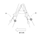
このような好ましくない歩き方を矯正するために、連結ロッドの角度を進行方向とは反対側に折り曲げるように調整することで、遠心力の働く領域を進行方向とは逆の方向に移動(回動)させることができるため(図3参照)、真横から見て後ろに腕を振る時の振り幅を大きくする方向に遠心力を利用して矯正するとともに、前に振る時の振り幅を小さくする方向に遠心力を利用して矯正することができ、前後にバランス良く腕を振ることができるようになる。 In order to correct this unfavorable way of walking, by adjusting the angle of the connecting rod so that it is bent to the opposite side of the traveling direction, the region where the centrifugal force works is moved in the direction opposite to the traveling direction (rotation). (See Fig. 3). Correcting by using centrifugal force in the direction to increase the swing width when swinging the arm backward as viewed from the side, and reducing the swing width when swinging forward It can be corrected using centrifugal force in the direction of movement, and the arm can be shaken in a well-balanced manner.
本願請求項2に係る腕振り矯正具は、連結ロッドが長さ調整機能を有しているため、使用者の好み及び目的に合わせて連結ロッドの長さを調整することで、物理学的に言えば慣性モーメント量を調整することで、歩行時に発生する遠心力の大きさを調整することができる。 In the arm swing correction tool according to claim 2 of the present application, since the connecting rod has a length adjusting function, it is physically possible to adjust the length of the connecting rod according to the user's preference and purpose. In other words, the magnitude of the centrifugal force generated during walking can be adjusted by adjusting the amount of moment of inertia.
本願請求項3に係る腕振り矯正具は、重量部又は連結ロッドに、重量部の最大断面積よりも面積の広い平板が、腕振り時に最も空気抵抗が生じないような向きに設置されている。これは、歩行時における腕振りの方向を矯正するためのものである。即ち、使用者は、腕振り歩行時に平板による空気抵抗を感じない方向に向かって腕振りすることで腕振りの角度が正しくなるように歩きながら調整することができる。 In the arm swing correction tool according to claim 3 of the present application, a flat plate having a larger area than the maximum cross-sectional area of the weight part is installed on the weight part or the connecting rod in such a direction that the air resistance does not occur most during arm swing. . This is for correcting the direction of arm swing during walking. That is, the user can adjust while walking so that the arm swing angle is correct by swinging the arm in a direction in which air resistance due to the flat plate is not felt during arm swing walking.
<腕振り矯正具の構造>
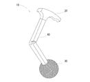
以下、本考案に係る腕振り矯正具10について、図1〜図3を参照しつつ詳細に説明する。図1は、腕振り矯正具10の全体図である。連結ロッド40の一端に握り部20が設置されている。握り部20は、右手又は左手の指を使って握るようにして掴む事ができるような形状になっている。連結ロッド40を挟んで、握り部20の反対側には、重さ200g〜300g(230g〜270gであればさらに好ましい)で直径30mm〜50mm程度の略球状の重量部30が設置されている。そして、握り部20と重量部30との間を繋ぐ長さ20cm〜40cm(長さ調整可能)の連結ロッド40が記載されている。
<Structure of arm swing corrector>
Hereinafter, the arm
連結ロッド40は、図1に示すように中心付近、または中心よりも握り部20側の部位に一般的な止め螺子等による角度調整機能を備えており、自由に角度を調整することができるようになっている。本発明の目的に合った通常の使用方法では「くの字」に折れ曲げる方向は、後方向に腕を振る時の振り幅を遠心力により矯正して大きくしようとするため、進行方向とは逆の方向としているが、骨格の歪み矯正等、使用者の目的に合わせて、進行方向と同じ方向に向かって折り曲げて使用することもできる。
As shown in FIG. 1, the connecting
さらに、連結ロッド40に重量部30の最大断面積よりも面積の広い厚さ2mm〜3mm程度の平板(図示しない)が、腕振り時に最も空気抵抗が生じないような向き(平板は腕振り方向と平行な関係にある)に設置することもできる。使用者はこの平板により、腕振り時に空気抵抗を感じない方向に向かって腕振りすることで腕振りの角度が正しくなるように歩きながら調整することができる。
Further, a flat plate (not shown) having a thickness of about 2 mm to 3 mm wider than the maximum cross-sectional area of the
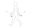
<腕振り矯正具の使用方法>
図2は、本発明に係る腕振り矯正具の使用状態を表す図である。図2に示すように本発明に係る腕振り矯正具は、単に、ウォーキング等の歩行時において右手と左手に1つずつ持って歩行するだけのものであり、極めて簡単に取り扱うことができる。
<How to use arm swing corrector>
FIG. 2 is a diagram illustrating a use state of the arm swing correction tool according to the present invention. As shown in FIG. 2, the arm swing correction tool according to the present invention is simply to walk with one right hand and one left hand during walking such as walking, and can be handled very easily.
通常の使用方法では「くの字」に折れ曲げる方向は、後方向に腕を振る時の振り幅を遠心力により矯正して大きくしようとするため、進行方向とは逆の方向としているが、体の左右の歪みを矯正するために、例えば右手に持った腕振り矯正具10だけを進行方向と同じ方向に「くの字」に折り曲げて使用することもできる。
In the normal usage method, the direction to bend into a `` shape '' is the direction opposite to the direction of travel, because the swing width when swinging the arm in the backward direction is to be corrected and increased by centrifugal force, In order to correct the left and right distortion of the body, for example, only the arm
<腕振り矯正具の効果>
本願発明に係る腕振り矯正具10は、連結ロッド40を介して握り部20の反対側に重量部30が設置されているため、歩行時において重量部30に重さがあることにより、腕振り時に遠心力が発生する。かかる遠心力により増強された腕振りによって、上半身(両肩部)の捻転運動が増強され、増強された上半身(両肩部)の捻転運動とのバランスを取るために、脚の蹴り出し及び下半身(腰部)の捻転運動も意識せずとも自然に増強された腕振りに引きずられて増強される。これによって体全体を大きく正しく動かすことができ、結果として正しい歩行動作が自然とできるようになる。
<Effect of arm swing corrector>
In the arm
本願発明に係る腕振り矯正具10は、連結ロッド40が角度調整機能を有しているため、使用者の好み及び目的に合わせて連結ロッド40の角度を調整することで、遠心力の働く領域を自由に調整することができる。
In the arm
人間の骨格構造上、進行方向に向かって前後に腕振りをする時、後ろ方向への腕振りの方が、前方向への腕振りよりも小さくなってしまうようになっている。この現象は、加齢とともに顕著に見られるようになる。その結果、加齢に伴って後ろ方向に腕を振る時の振り幅が小さくなり、これに合わせて前に振る時の振り幅も小さくなると考えられる。 Due to the human skeletal structure, when swinging back and forth in the direction of travel, swinging backward is less than swinging forward. This phenomenon becomes prominent with aging. As a result, it is considered that the swing width when swinging the arm in the backward direction is reduced with aging, and the swing width when swinging forward is also reduced in accordance with this.
後ろに腕を振る時の振り幅が小さくなった結果、中高齢者が、腕を大きく振ろうと意識して一生懸命に歩くと、腕振りし易い前方にばかり腕を振り上げて、腕振りし難い後方へは腕が振れていないという現象が起こり、前後にバランス良く腕を振るという歩行の理想形からはかけ離れた状態になってしまう。 As a result of the swing width when swinging the arm behind, when middle aged people walk hard with awareness of trying to swing their arms greatly, it is difficult to swing their arms by swinging up the arms just ahead of the arm The phenomenon that the arm does not swing backward occurs, and it is far from the ideal form of walking where the arm is swinged back and forth in a balanced manner.
図3は連結ロッドの角度調整機能による効果を説明する図である。本願発明に係る腕振り矯正具10は、比較的高年齢で筋力が低下してしまった人であっても、重さによる疲労を感じることなく、上記のような好ましくない歩き方を矯正するために、連結ロッド40の角度を進行方向とは反対側に折り曲げるように調整することで、遠心力の働く領域を進行方向とは逆の方向に移動(回動)させることができるため(図3の点線の範囲から実線の範囲へ移動)、真横から見て後ろに腕を振る時の振り幅を大きくする方向に遠心力を利用して矯正するとともに、前に振る時の振り幅を小さくする方向に遠心力を利用して矯正することができ、前後にバランス良く腕を振ることができるようになる。
FIG. 3 is a diagram for explaining the effect of the connecting rod angle adjusting function. The arm
後ろに腕を振る時の振り幅を大きくする方向に、遠心力による矯正効果をより大きくするためには、略中心部よりも握り部側の部位において角度調整機能を有することが望ましいと言える。 In order to increase the correction effect by centrifugal force in the direction of increasing the swing width when swinging the arm backward, it can be said that it is desirable to have an angle adjustment function at a position closer to the grip part than the center part.
さらに、本願発明に係る腕振り矯正具10は、重量部30又は連結ロッド40に、重量部30の最大断面積よりも面積の広い平板(図示しない)が、腕振り時に最も空気抵抗が生じないような向きに設置されている。これは、歩行時における腕振りの方向を矯正するためのものである。即ち、使用者は、腕振り歩行時に平板による空気抵抗を感じない方向に向かって腕振りすることで腕振りの角度が正しくなるように歩きながら調整することができる。
Furthermore, in the arm
<腕振り矯正具の変更例>
本発明に係る腕振り矯正具10の構成は、上記実施形態の態様に何ら限定されるものではなく、握り部20、重量部30、連結ロッド40、平板等の構成を、本発明の趣旨を逸脱しない範囲で、必要に応じて適宜変更することができる。例えば、右手及び左手と握り部20とをそれぞれベルト等で固定して使用することもできる。
<Examples of changing arm swing correction tools>
The configuration of the arm
本発明に係る腕振り矯正具は、上記の如く優れた効果を奏するものであるので、歩行者が正しい腕振りをすることにより自然に正しい歩き方を身に着けることができることを目的とする歩行矯正具の分野で好適に用いることができる。 Since the arm swing correction tool according to the present invention has excellent effects as described above, the walk intended to enable the pedestrian to wear the correct way of walking naturally by swinging the correct arm. It can be suitably used in the field of correction tools.
10・・腕振り矯正具
20・・握り部
30・・重量部
40・・連結ロッド
10.
Claims (3)
右手又は左手で握るための握り部と、
前記握り部の反対側に設置された重量部と、
前記握り部と前記重量部との間を繋いでおり、略中心部もしくは略中心部よりも握り部側の部位において角度調整機能を有する連結ロッドとからなる腕振り矯正具。 An instrument for walking with one right hand and one left hand
A grip for gripping with the right or left hand;
A weight part installed on the opposite side of the grip part;
An arm swing correction tool that is connected to the grip portion and the weight portion and includes a connecting rod having an angle adjusting function at a substantially central portion or a portion closer to the grip portion than the substantially central portion.
Priority Applications (1)
| Application Number | Priority Date | Filing Date | Title |
|---|---|---|---|
| JP2013211652A JP6100667B2 (en) | 2013-10-09 | 2013-10-09 | Arm swing correction tool |
Applications Claiming Priority (1)
| Application Number | Priority Date | Filing Date | Title |
|---|---|---|---|
| JP2013211652A JP6100667B2 (en) | 2013-10-09 | 2013-10-09 | Arm swing correction tool |
Publications (2)
| Publication Number | Publication Date |
|---|---|
| JP2015073722A true JP2015073722A (en) | 2015-04-20 |
| JP6100667B2 JP6100667B2 (en) | 2017-03-22 |
Family
ID=52999051
Family Applications (1)
| Application Number | Title | Priority Date | Filing Date |
|---|---|---|---|
| JP2013211652A Expired - Fee Related JP6100667B2 (en) | 2013-10-09 | 2013-10-09 | Arm swing correction tool |
Country Status (1)
| Country | Link |
|---|---|
| JP (1) | JP6100667B2 (en) |
Cited By (1)
| Publication number | Priority date | Publication date | Assignee | Title |
|---|---|---|---|---|
| KR100628467B1 (en) * | 2004-12-17 | 2006-09-26 | 주식회사 천지테크 | Surface treatment method for improving the strength of iron ore |
Citations (4)
| Publication number | Priority date | Publication date | Assignee | Title |
|---|---|---|---|---|
| US5378217A (en) * | 1993-08-17 | 1995-01-03 | D'orta; Frank A. | Hand held exercise device providing desirable air resistance |
| JP3023317B2 (en) * | 1996-10-02 | 2000-03-21 | 株式会社ナムコ | Game system |
| US20070135273A1 (en) * | 2005-12-13 | 2007-06-14 | Michael Ljevaja | Weight securing system |
| US20130190145A1 (en) * | 2011-07-07 | 2013-07-25 | David A. Kugielsky | Dynamic Weight Training Apparatus |
-
2013
- 2013-10-09 JP JP2013211652A patent/JP6100667B2/en not_active Expired - Fee Related
Patent Citations (4)
| Publication number | Priority date | Publication date | Assignee | Title |
|---|---|---|---|---|
| US5378217A (en) * | 1993-08-17 | 1995-01-03 | D'orta; Frank A. | Hand held exercise device providing desirable air resistance |
| JP3023317B2 (en) * | 1996-10-02 | 2000-03-21 | 株式会社ナムコ | Game system |
| US20070135273A1 (en) * | 2005-12-13 | 2007-06-14 | Michael Ljevaja | Weight securing system |
| US20130190145A1 (en) * | 2011-07-07 | 2013-07-25 | David A. Kugielsky | Dynamic Weight Training Apparatus |
Cited By (1)
| Publication number | Priority date | Publication date | Assignee | Title |
|---|---|---|---|---|
| KR100628467B1 (en) * | 2004-12-17 | 2006-09-26 | 주식회사 천지테크 | Surface treatment method for improving the strength of iron ore |
Also Published As
| Publication number | Publication date |
|---|---|
| JP6100667B2 (en) | 2017-03-22 |
Similar Documents
| Publication | Publication Date | Title |
|---|---|---|
| JPWO2011049171A1 (en) | Exercise assist device, control method thereof, and rehabilitation method | |
| AU2015292270B2 (en) | A training device for limiting the movement of a player's forearm during a sporting action | |
| US8083702B2 (en) | Walking assistance device | |
| JP6100667B2 (en) | Arm swing correction tool | |
| JP2008194469A (en) | Exercise device | |
| US11648144B2 (en) | Device for correcting forward head posture | |
| CN220002037U (en) | Scoliosis orthopedic trainer | |
| CN205515087U (en) | Hip medical treatment tractor is divided to spasm type cerebral palsy children developments | |
| CN211214211U (en) | Lower limb rehabilitation exoskeleton and lower limb rehabilitation system | |
| CN204133659U (en) | Ankle joint orthotic device | |
| TW201540283A (en) | Massage device | |
| JP7351556B1 (en) | Canes and cane shafts | |
| US12145025B2 (en) | Extremity flexion and extension exerciser devices | |
| JP5143308B1 (en) | Body axis corrector | |
| KR101565151B1 (en) | Cane with handle and forearm holding pad | |
| JP2016101193A (en) | Rocking footrest for chair | |
| US8998744B1 (en) | Ergonomic handle golf club | |
| CN204617444U (en) | A kind of two wrist and both arms health care supporting plate | |
| CN202504861U (en) | U-shaped neck pillow | |
| CN105287080A (en) | Upper support and traction functional training cervical gear using same | |
| CN109568886A (en) | A kind of connecting rod suitable for leg muscle training aids | |
| JP3198846U (en) | Rubber belt exercise equipment | |
| CN206560507U (en) | A kind of zero-g wheelchair frame | |
| CN105476813B (en) | Standing bed with ankle-joint training function | |
| JP2010088715A (en) | Exercise implement for correcting ball-catching posture for baseball and softball |
Legal Events
| Date | Code | Title | Description |
|---|---|---|---|
| A621 | Written request for application examination |
Free format text: JAPANESE INTERMEDIATE CODE: A621 Effective date: 20160518 |
|
| A871 | Explanation of circumstances concerning accelerated examination |
Free format text: JAPANESE INTERMEDIATE CODE: A871 Effective date: 20160928 |
|
| A975 | Report on accelerated examination |
Free format text: JAPANESE INTERMEDIATE CODE: A971005 Effective date: 20161014 |
|
| A131 | Notification of reasons for refusal |
Free format text: JAPANESE INTERMEDIATE CODE: A131 Effective date: 20161025 |
|
| A521 | Written amendment |
Free format text: JAPANESE INTERMEDIATE CODE: A523 Effective date: 20161122 |
|
| A131 | Notification of reasons for refusal |
Free format text: JAPANESE INTERMEDIATE CODE: A131 Effective date: 20161209 |
|
| A521 | Written amendment |
Free format text: JAPANESE INTERMEDIATE CODE: A523 Effective date: 20170111 |
|
| TRDD | Decision of grant or rejection written | ||
| A01 | Written decision to grant a patent or to grant a registration (utility model) |
Free format text: JAPANESE INTERMEDIATE CODE: A01 Effective date: 20170117 |
|
| R150 | Certificate of patent or registration of utility model |
Ref document number: 6100667 Country of ref document: JP Free format text: JAPANESE INTERMEDIATE CODE: R150 |
|
| LAPS | Cancellation because of no payment of annual fees |