JP2015071438A - Storage container for precision instrument - Google Patents

Storage container for precision instrument Download PDF

Info

Publication number
JP2015071438A
JP2015071438A JP2013207723A JP2013207723A JP2015071438A JP 2015071438 A JP2015071438 A JP 2015071438A JP 2013207723 A JP2013207723 A JP 2013207723A JP 2013207723 A JP2013207723 A JP 2013207723A JP 2015071438 A JP2015071438 A JP 2015071438A
Authority
JP
Japan
Prior art keywords
flap
bottom wall
partition member
partition
vertical wall
Prior art date
Legal status (The legal status is an assumption and is not a legal conclusion. Google has not performed a legal analysis and makes no representation as to the accuracy of the status listed.)
Pending
Application number
JP2013207723A
Other languages
Japanese (ja)
Inventor
史彰 荒井
Fumiaki Arai
史彰 荒井
泰弘 西堀
Yasuhiro Nishibori
泰弘 西堀
吉田 季央
Sueo Yoshida
季央 吉田
Current Assignee (The listed assignees may be inaccurate. Google has not performed a legal analysis and makes no representation or warranty as to the accuracy of the list.)
Otsuka Packaging Industries Co Ltd
Original Assignee
Otsuka Packaging Industries Co Ltd
Priority date (The priority date is an assumption and is not a legal conclusion. Google has not performed a legal analysis and makes no representation as to the accuracy of the date listed.)
Filing date
Publication date
Application filed by Otsuka Packaging Industries Co Ltd filed Critical Otsuka Packaging Industries Co Ltd
Priority to JP2013207723A priority Critical patent/JP2015071438A/en
Publication of JP2015071438A publication Critical patent/JP2015071438A/en
Pending legal-status Critical Current

Links

Images

Abstract

PROBLEM TO BE SOLVED: To provide a storage container for a precision instrument in which a partitioning body placed inside a storage box can be assembled by a box-making machine and a precision instrument as a stored object can be stored in a partitioning body by using a machine.SOLUTION: A partitioning body 3 includes a plurality of partitioning members 4. The partitioning member 4 includes a bottom wall 5, vertical walls 6, 7 standing from both ends of the bottom wall 5, and flaps 8, 9 for connecting side parts of the vertical walls 6, 7 connected to both side parts of the vertical walls 6, 7 and facing to each other. The flap 8 includes projected parts 8c, 8e engaging with the flap 8 of the adjacently-arranged partitioning member 4 and a hole part 8a and a recessed part 8d which are engaged with the projected parts 8c, 8e of the flap 8 of the adjacently-arranged partitioning member 4. The bottom wall 5 includes a projected part 5c engaging with the bottom wall 5 of the adjacently-arranged partitioning member 4, and a hole part 5a engaging with the projected part 5c arranged on the bottom wall 5 of the adjacently-arranged partitioning member 4.

Description

本発明は、精密機器を収納する精密機器用収納容器に関する。   The present invention relates to a storage container for precision equipment that houses precision equipment.

精密機器は、輸送時や保管時に外部からの衝撃を受けることを回避するため、専用の収納容器に収納した状態で輸送等される。例えば、発光ダイオード(Light Emitting Diode:以下「LED」という。)の輸送には、リール状に巻かれた状態で収納できるよう、複数のスリット状に形成された専用の精密機器用収納容器が使用される。LEDを収納する精密機器用収納容器の一例を図20に示す。この精密機器用収納容器21は、収納箱22と、収納箱22の内部に載置される仕切り体23とを備えている。仕切り体23は、底壁24と、底壁24の両端部から立ち上がる側壁25とを備え断面がコの字状の本体部26と、本体部26の開口部から挿入されて本体部26の内部を仕切る複数の仕切り板27とを備えている。
仕切り体23には、本体部26を仕切り板27で仕切った複数の空間28が形成されており、これらの空間28には袋詰めされたLEDリールが縦方向に3袋ずつ収納される。仕切り体23には幅狭な空間29,30が設けられており、空間29にはLEDリールを2つ収納することができ、空間30にはLEDリールを1つ収納することができる。これによって任意の個数のLEDリールを収納することができる。
Precision equipment is transported in a state of being stored in a dedicated storage container in order to avoid receiving external impacts during transportation and storage. For example, when transporting light emitting diodes (hereinafter referred to as “LEDs”), dedicated precision instrument storage containers formed into a plurality of slits are used so that they can be stored in a reel shape. Is done. An example of the storage container for precision instruments that stores the LED is shown in FIG. The precision instrument storage container 21 includes a storage box 22 and a partition body 23 placed inside the storage box 22. The partition body 23 includes a bottom wall 24 and side walls 25 rising from both ends of the bottom wall 24, and is inserted into the main body portion 26 having a U-shaped cross section and an opening of the main body portion 26. And a plurality of partition plates 27 are provided.
The partition body 23 is formed with a plurality of spaces 28 in which the main body portion 26 is partitioned by a partition plate 27, and in each of these spaces 28, the packed LED reels are stored three by three in the vertical direction. The partition body 23 is provided with narrow spaces 29 and 30. The space 29 can store two LED reels, and the space 30 can store one LED reel. As a result, an arbitrary number of LED reels can be stored.

特開2011−189969号公報JP 2011-189969 A

このような精密機器用収納容器はブランク材を手作業で組み立てて形成されている。さらに組み立てられた精密機器用収納容器には、袋詰めされたLEDリールが手作業で収納されているので手間が掛かる。   Such a container for precision equipment is formed by manually assembling a blank material. Furthermore, the assembled precision equipment storage container is troublesome because the LED reel packed in a bag is stored manually.

本発明は、従来のこのような問題点を解決するためになされたものである。本発明の主な目的は、収納箱の内部に載置される仕切り体を製函機によって組み立てることができると共に、収納物である精密機器を機械を用いて仕切り体に収納することができる精密機器用収納容器を提供することである。   The present invention has been made to solve such conventional problems. The main object of the present invention is to be able to assemble a partition body placed inside a storage box by a box making machine, and to be able to store a precision instrument as a storage object in a partition body using a machine. It is to provide a storage container for equipment.

課題を解決するための手段及び発明の効果Means for Solving the Problems and Effects of the Invention

上記目的を達成するために、本発明の一の精密機器用収納容器によれば、収納箱と、収納箱の内部に設置される仕切り体とを備えた精密機器用収納容器において、仕切り体は、隣合わせに配置され収納物が収納される複数個の仕切り部材を備えており、前記仕切り部材は、底壁と、底壁の両端から立ち上がる縦壁と、縦壁の両側部に連設され対向する縦壁の側部を接続するフラップとを備え、前記フラップには、隣合わせに配置される仕切り部材のフラップに係合する第1の係合部と、隣合わせに配置される仕切り部材のフラップの係合部が係合する第1の被係合部とがフラップと一体に形成されており、前記底壁には隣合わせに配置される仕切り部材の底壁に係合する第2の係合部と、隣合わせに配置される仕切り部材の底壁に設けられた係合部が係合する第2の被係合部が底壁と一体的に設けられている。   In order to achieve the above object, according to the precision instrument storage container of the present invention, in the precision instrument storage container comprising a storage box and a partition installed inside the storage box, the partition body is And a plurality of partition members arranged next to each other to store the stored items, the partition members being connected to and opposed to the bottom wall, the vertical wall rising from both ends of the bottom wall, and both sides of the vertical wall. A flap that connects side portions of the vertical wall, and the flap includes a first engagement portion that engages with a flap of a partition member that is disposed next to each other, and a flap of the partition member that is disposed next to each other. A first engaged portion with which the engaging portion engages is formed integrally with the flap, and the second engaging portion engages with the bottom wall of the partition member arranged next to the bottom wall. And provided on the bottom wall of the partition member arranged next to each other Second engaged portion engaging portion is engaged is provided on the bottom wall integrally.

上記構成によると、収納物である精密機器を機械を用いて仕切り部材のブランク材に載置した状態で、製函機を用いて仕切り部材を組み立てて、仕切り部材の組み立てと同時に収納物を仕切り部材に収納することができる。組み立てられた仕切り部材は、機械を用いて、第1の係合部と第2の係合部とが隣合わせに配置される仕切り部材に係合した状態で複数個が隣合わせに互いに当接した状態で並べられる。複数個が互いに当接した状態で並べられた仕切り部材は、機械を用いて収納箱に収納することができる。   According to the above configuration, in a state in which the precision instrument that is the stored item is placed on the partition member blank using a machine, the partition member is assembled using the box making machine, and the stored item is partitioned simultaneously with the assembly of the partition member. It can be stored in a member. The assembled partition member is in a state where a plurality of the first engaging portion and the second engaging portion are in contact with each other side by side while the first engaging portion and the second engaging portion are engaged with the partition member arranged next to each other. Are arranged in The partition members arranged in a state where a plurality are in contact with each other can be stored in a storage box using a machine.

また、第1の係合部はフラップの基端部および/または先端部に連設された凸部である。   Further, the first engaging portion is a convex portion provided continuously to the proximal end portion and / or the distal end portion of the flap.

上記構成によると、第1の係合部を簡単に形成することができる。   According to the said structure, a 1st engaging part can be formed easily.

また、第1の被係合部はフラップの基端部に形成された孔部および/またはフラップの先端部に形成された凹部である   The first engaged portion is a hole formed at the base end of the flap and / or a recess formed at the tip of the flap.

上記構成によると、第1の被係合部を簡単に形成することができる。   According to the said structure, a 1st to-be-engaged part can be formed easily.

また、第2の係合部は底壁に形成された舌片である。   The second engagement portion is a tongue piece formed on the bottom wall.

上記構成によると、第2の係合部を簡単に形成することができる。   According to the said structure, a 2nd engaging part can be formed easily.

また、第2の被係合部は底壁に形成された孔部である。   The second engaged portion is a hole formed in the bottom wall.

上記構成によると、第2の被係合部を簡単に形成することができる。   According to the said structure, a 2nd to-be-engaged part can be formed easily.

また、仕切り体の端部に位置する仕切り部材は前記第1の係合部が収納箱の内面に当接する。   Moreover, the partition member located at the end of the partition body has the first engaging portion abutting against the inner surface of the storage box.

上記構成によると、収納箱の内部に収納される仕切り体が収納箱の内面に直接当接しないようにして、収納箱が受けた衝撃が収納物に伝わることを緩和することができる。   According to the said structure, it can ease that the partition received by the inside of a storage box does not contact | abut directly to the inner surface of a storage box, and the impact which the storage box received is transmitted to a storage thing.

また、縦壁は底壁に向かって幅狭なテーパ状に形成されている。   Further, the vertical wall is formed in a tapered shape having a narrow width toward the bottom wall.

上記構成によると、収納箱の内部に収納される仕切り体が収納箱の内面に直接当接しないようにして、収納箱が受けた衝撃が収納物に伝わることを緩和することができる。   According to the said structure, it can ease that the partition received by the inside of a storage box does not contact | abut directly to the inner surface of a storage box, and the impact which the storage box received is transmitted to a storage thing.

本発明の第1の実施形態に係る精密機器用収納容器の斜視図である。It is a perspective view of the storage container for precision instruments which concerns on the 1st Embodiment of this invention. 仕切り部材の展開図である。It is an expanded view of a partition member. 組み立てられた仕切り部材の斜視図である。It is a perspective view of the assembled partition member. 組み立てられた仕切り部材の斜視図である。It is a perspective view of the assembled partition member. 仕切り部材を連結して仕切り体を形成する手順を示す斜視図である。It is a perspective view which shows the procedure which connects a partition member and forms a partition body. 仕切り体の斜視図である。It is a perspective view of a partition body. 仕切り片の斜視図である。It is a perspective view of a partition piece. 仕切り片が収納された仕切り体の斜視図である。It is a perspective view of the partition body in which the partition piece was accommodated. 本発明の第2の実施形態に係る仕切り部材の展開図である。It is an expanded view of the partition member which concerns on the 2nd Embodiment of this invention. 組み立てられた仕切り部材の斜視図である。It is a perspective view of the assembled partition member. 複数個の仕切り部材を連結して形成された仕切り体の斜視図である。It is a perspective view of the partition body formed by connecting a plurality of partition members. 側板の平面図である。It is a top view of a side plate. 仕切り板の平面図である。It is a top view of a partition plate. 収納箱の展開図である。It is an expanded view of a storage box. 仕切り体が収納箱に収納された状態の斜視図である。It is a perspective view of the state where the partition was stored in the storage box. 本発明の第3の実施形態に係る仕切り部材の展開図である。It is an expanded view of the partition member which concerns on the 3rd Embodiment of this invention. 組み立てられた仕切り部材の斜視図である。It is a perspective view of the assembled partition member. 複数個の仕切り部材を連結して形成された仕切り体の斜視図である。It is a perspective view of the partition body formed by connecting a plurality of partition members. 側板の平面図である。It is a top view of a side plate. 従来の精密機器用収納容器の斜視図である。It is a perspective view of the conventional storage container for precision instruments.

以下、本発明の第1の実施形態について図面に基づいて説明する。ただし、以下に示す実施例は、本発明の技術思想を具体化するための精密機器用収納容器を例示するものであって、精密機器用収納容器を以下のものに特定するものではない。   DESCRIPTION OF EXEMPLARY EMBODIMENTS Hereinafter, a first embodiment of the invention will be described with reference to the drawings. However, the examples shown below exemplify the storage container for precision equipment for embodying the technical idea of the present invention, and do not specify the storage container for precision equipment as follows.

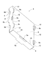
図1は本発明の第1の実施形態に係る精密機器用収納容器1の斜視図である。図2は、仕切り部材4の展開図である。精密機器用収納容器1は、収納箱2と、収納箱2に収納される仕切り体3とを備えている。仕切り体3は、隣合わせに連結され収納物が収納される複数個の仕切り部材4を備えている。   FIG. 1 is a perspective view of a precision instrument storage container 1 according to a first embodiment of the present invention. FIG. 2 is a development view of the partition member 4. The precision instrument storage container 1 includes a storage box 2 and a partition body 3 stored in the storage box 2. The partition body 3 is provided with a plurality of partition members 4 that are connected side by side and store stored items.

仕切り部材4は、展開された状態で、底壁5と、底壁5の両端に連設される縦壁6と縦壁7とを備えている。縦壁6の両側部にはフラップ8が連設されており、縦壁7の両側部にはフラップ9が連設されている。底壁5と縦壁6とを連結する折曲線10の中央部には孔部5aが形成されており、底壁5と縦壁7とを連結する折曲線11の中央部にはコの字状の切欠線5bが形成されている。   The partition member 4 includes a bottom wall 5, and a vertical wall 6 and a vertical wall 7 that are connected to both ends of the bottom wall 5 in an unfolded state. A flap 8 is provided on both sides of the vertical wall 6, and a flap 9 is provided on both sides of the vertical wall 7. A hole 5 a is formed at the center of the folding line 10 that connects the bottom wall 5 and the vertical wall 6, and a U-shape is formed at the center of the folding line 11 that connects the bottom wall 5 and the vertical wall 7. A notch line 5b is formed.

縦壁6とフラップ8とを連結する折曲線12の中央部には第1の被係合部である孔部8aが形成されており、孔部8aの両側にはコの字状の切欠線8bが形成されている。フラップ8の先端部には第1の係合部であるコの字状の凸部8cがフラップ8の中央部に形成されており、凸部8cの両側には第1の被係合部であるコの字状の凹部8dが形成されている。縦壁6とフラップ8とを連結する折曲線12は傾斜しており、縦壁6は底壁5に向かって幅狭に形成されている。さらに縦壁7とフラップ9とを連結する折曲線13は傾斜しており、縦壁7は底壁5に向かって幅狭に形成されている。   A hole 8a, which is a first engaged portion, is formed at the center of the folding line 12 that connects the vertical wall 6 and the flap 8. A U-shaped notch line is formed on both sides of the hole 8a. 8b is formed. A U-shaped convex portion 8c, which is a first engaging portion, is formed at the center of the flap 8 at the front end portion of the flap 8, and a first engaged portion is formed on both sides of the convex portion 8c. A U-shaped recess 8d is formed. The folding line 12 connecting the vertical wall 6 and the flap 8 is inclined, and the vertical wall 6 is formed narrower toward the bottom wall 5. Further, the folding line 13 connecting the vertical wall 7 and the flap 9 is inclined, and the vertical wall 7 is formed narrower toward the bottom wall 5.

図3,図4は組み立てられた仕切り部材4の斜視図である。図2に示すブランク材は、底壁5の両端に連設された縦壁6と縦壁7とがそれぞれ折曲線10と11とで折り曲げられ、縦壁6と縦壁7とが対向するように断面がコの字状に形成される。縦壁7の両側部に形成されたフラップ9は折曲線13で折り曲げられ、縦壁6の両側部に形成されたフラップ8は折曲線12で折り曲げられる。フラップ8はフラップ9に接着され、開口部14を備えた箱形の仕切り部材4が形成される。これらの組み立て作業は、ブランク材に収納物を載置した状態で、製函機を用いて行うことができる。たとえばブランク材の縦壁7に収納物を載置した状態で組み立てて、仕切り部材4の組み立て作業と同時に収納物を仕切り部材4に収納することができる。   3 and 4 are perspective views of the assembled partition member 4. In the blank shown in FIG. 2, the vertical wall 6 and the vertical wall 7 connected to both ends of the bottom wall 5 are bent at folding lines 10 and 11, respectively, so that the vertical wall 6 and the vertical wall 7 face each other. The cross section is formed in a U shape. The flaps 9 formed on both sides of the vertical wall 7 are bent along a folding line 13, and the flaps 8 formed on both sides of the vertical wall 6 are bent along a folding line 12. The flap 8 is bonded to the flap 9 to form a box-shaped partition member 4 having an opening 14. These assembling operations can be performed using a box making machine in a state where a stored item is placed on a blank material. For example, the stored items can be assembled in a state where the stored items are placed on the vertical wall 7 of the blank material, and the stored items can be stored in the partition member 4 simultaneously with the assembling work of the partition member 4.

底壁5と縦壁7との接続部(折曲線11)の中央部には、底壁5と一体に形成され、切欠線5bに沿って突出する第2の係合部である凸部5cが形成される。凸部5cは縦壁7の下端において縦壁7の外側に突出している。底壁5と縦壁6との接続部(折曲線10)の中央部には第2の被係合部である孔部5aが形成されている。   A convex portion 5c, which is a second engaging portion that is formed integrally with the bottom wall 5 and protrudes along the notch line 5b, at the center of the connecting portion (folding curve 11) between the bottom wall 5 and the vertical wall 7. Is formed. The convex portion 5 c protrudes outside the vertical wall 7 at the lower end of the vertical wall 7. A hole 5a, which is a second engaged portion, is formed at the center of the connecting portion (folding curve 10) between the bottom wall 5 and the vertical wall 6.

フラップ8の基端部(折曲線12)には、フラップ8と一体に形成され、切欠線8bに沿って突出する第1の係合部である凸部8eが孔部8aの両側に形成される。凸部8eは縦壁6の両側部において縦壁6の外側に突出している。フラップ8の先端部中央には、凸部8cがフラップ8と一体に形成されている。凸部8cは縦壁7の両側部において縦壁7の外側に突出している。凸部8cの両側にはコの字状の凹部8dが形成されている。   On the base end portion (folding curve 12) of the flap 8, convex portions 8e that are formed integrally with the flap 8 and project along the notch line 8b are formed on both sides of the hole portion 8a. The The convex part 8e protrudes to the outside of the vertical wall 6 at both sides of the vertical wall 6. A convex portion 8 c is formed integrally with the flap 8 at the center of the front end portion of the flap 8. The convex portion 8 c protrudes outside the vertical wall 7 at both sides of the vertical wall 7. U-shaped concave portions 8d are formed on both sides of the convex portion 8c.

図5は複数個の仕切り部材4を連結して仕切り体3を形成する手順を示す。 仕切り部材4Aの凸部8cが、 仕切り部材4Aの一方側に位置する仕切り部材4Cの孔部8aに係合し、仕切り部材4Cの凸部8eが仕切り部材4Aの凹部8dに係合する。 仕切り部材4Aの凸部8eは、 仕切り部材4Aの他方側に位置する仕切り部材4Bの凹部8dに係合し、仕切り部材4Bの凸部8cが仕切り部材4Aの凹部8aに係合する。   FIG. 5 shows a procedure for forming a partition body 3 by connecting a plurality of partition members 4. The convex part 8c of the partition member 4A engages with the hole 8a of the partition member 4C located on one side of the partition member 4A, and the convex part 8e of the partition member 4C engages with the concave part 8d of the partition member 4A. The convex portion 8e of the partition member 4A engages with the concave portion 8d of the partition member 4B located on the other side of the partition member 4A, and the convex portion 8c of the partition member 4B engages with the concave portion 8a of the partition member 4A.

仕切り部材4Aの凸部8cと凸部8eとは、それぞれ弾性変形して相手側の仕切り部材4C,4Bを両側から挟み込む。同様に、仕切り部材4Cの凸部8eは、弾性変形して仕切り部材4Aを両側から挟み込み、仕切り部材4Bの凸部8cは、弾性変形して仕切り部材4Aを両側から挟み込む。仕切り部材4Aの底壁5に形成された凸部5cは、仕切り部材4Cの底壁5に形成された孔部5aに係合し、仕切り部材4Aの底壁5に形成された孔部5aには、仕切り部材4Bに形成された凸部5cが係合する。   The convex portion 8c and the convex portion 8e of the partition member 4A are elastically deformed to sandwich the mating partition members 4C and 4B from both sides. Similarly, the convex portion 8e of the partition member 4C is elastically deformed to sandwich the partition member 4A from both sides, and the convex portion 8c of the partition member 4B is elastically deformed to sandwich the partition member 4A from both sides. The protrusion 5c formed on the bottom wall 5 of the partition member 4A engages with the hole 5a formed on the bottom wall 5 of the partition member 4C, and the hole 5a formed on the bottom wall 5 of the partition member 4A. Is engaged with the convex portion 5c formed on the partition member 4B.

これらの仕切り部材4を連結して仕切り体3を形成する作業は、機械を用いて行うことができる。たとえば縦壁7を水平方向に位置させた状態で、仕切り部材4を積み上げて仕切り体3を形成することができる。仕切り部材4を連結して形成した仕切り体3を図6に示す。   The operation | work which connects these partition members 4 and forms the partition body 3 can be performed using a machine. For example, the partition body 3 can be formed by stacking the partition members 4 with the vertical wall 7 positioned in the horizontal direction. A partition 3 formed by connecting partition members 4 is shown in FIG.

本実施の形態では、収納物として、袋詰めされたLEDリールが用いられており、各仕切り部材4にはLEDリールが3つずつ収納されるが、仕切り片16(図7を参照のこと。)を用いることによって、仕切り部材4にLEDリールを1つあるいは2つ収納することもできる。仕切り片16は、ブランク材をコの字状に曲げ加工して形成される。2つの側辺16aの基端部には凸部16bが2箇所に形成されており、仕切り片16の断面はH状である。仕切り片16は仕切り部材4と同様に製函機を用いて形成することができる。側辺16aは凸部16bよりも幅広に形成されており、側辺16a側にはLEDリールを2つ収納することができ、凸部16b側にはLEDリールを1つ収納することができる。仕切り部材4に仕切り片16が収納された状態を図8に示す。   In the present embodiment, bag-packed LED reels are used as the stored items, and three LED reels are stored in each partition member 4, but the partition pieces 16 (see FIG. 7). ) Can be used to store one or two LED reels in the partition member 4. The partition piece 16 is formed by bending a blank material into a U-shape. Convex portions 16b are formed at two locations on the base end portions of the two side edges 16a, and the partition piece 16 has an H-shaped cross section. The partition piece 16 can be formed using a box making machine in the same manner as the partition member 4. The side 16a is formed wider than the convex portion 16b, and two LED reels can be stored on the side 16a side, and one LED reel can be stored on the convex portion 16b side. FIG. 8 shows a state in which the partition piece 16 is stored in the partition member 4.

仕切り部材4は、縦壁6と縦壁7とが底壁5に向かって幅狭なテーパ状に形成されているので、図1に示すように、仕切り体3の上部18が収納箱2の内面に当接した状態で収納されたとき、仕切り体3の下部には隙間19が形成される。仕切り体3の端部に位置する仕切り部材4から、凸部8c,凸部5cおよび凸部8eが、仕切り部材4の連結方向に突出しており、この凸部8c,凸部5cおよび凸部8eが収納箱2の内面に当接するので、仕切り体3の端部に位置する縦壁6,縦壁7と収納箱2の内面との間には隙間20が形成される。これによって、収納箱2が受けた衝撃が収納物に伝わることを緩和することができる。   In the partition member 4, the vertical wall 6 and the vertical wall 7 are formed in a tapered shape having a narrow width toward the bottom wall 5, so that the upper portion 18 of the partition body 3 is the storage box 2 as shown in FIG. 1. When stored in contact with the inner surface, a gap 19 is formed in the lower part of the partition 3. From the partition member 4 located at the end portion of the partition body 3, the convex portion 8c, the convex portion 5c, and the convex portion 8e protrude in the connecting direction of the partition member 4, and the convex portion 8c, the convex portion 5c, and the convex portion 8e. Is in contact with the inner surface of the storage box 2, so that a gap 20 is formed between the vertical walls 6 and 7 located at the end of the partition 3 and the inner surface of the storage box 2. Thereby, it is possible to mitigate the impact received by the storage box 2 from being transmitted to the stored items.

本発明の第2の実施形態について図面に基づいて説明する。図9に示すように、展開された状態で仕切り部材34は、底壁35と、底壁35の両端に連設される縦壁36と縦壁37とを備えている。縦壁36の両側部にはフラップ38とフラップ39とが連設されており、縦壁37の両側部にはフラップ40とフラップ41とが連設されている。フラップ38とフラップ39との間には切り欠き42が形成されており、フラップ40とフラップ41との間には切り欠き43が形成されている。フラップ39の側部には凸部44が形成されている。   A second embodiment of the present invention will be described with reference to the drawings. As shown in FIG. 9, the partition member 34 includes a bottom wall 35, and a vertical wall 36 and a vertical wall 37 that are connected to both ends of the bottom wall 35 in the unfolded state. A flap 38 and a flap 39 are connected to both sides of the vertical wall 36, and a flap 40 and a flap 41 are connected to both sides of the vertical wall 37. A notch 42 is formed between the flap 38 and the flap 39, and a notch 43 is formed between the flap 40 and the flap 41. A convex portion 44 is formed on the side portion of the flap 39.

底壁35には孔部47が2箇所に形成されており、孔部47の側辺48は凸状に形成されている。縦壁36と縦壁37とを対向するように折り曲げたときた側辺48によって脚部が形成される。   Two holes 47 are formed in the bottom wall 35, and the side 48 of the hole 47 is formed in a convex shape. Legs are formed by the side edges 48 that are bent when the vertical wall 36 and the vertical wall 37 are opposed to each other.

図10は組み立てられた仕切り部材34の斜視図である。図2に示すブランク材は、底壁35の両端に連設された縦壁36と縦壁37とがそれぞれ折曲線50と51とで折り曲げられ、縦壁36と縦壁37とが対向するように断面がコの字状に形成される。フラップ38とフラップ39とは折曲線54で折り曲げられ、フラップ40とフラップ41とは折曲線55で折り曲げられる。そしてフラップ38とフラップ40とが接着され、フラップ39とフラップ41とが接着されて、長方形の孔部57が形成される。これらの組み立て作業は、ブランク材に収納物を載置した状態で、製函機を用いて行うことができる。たとえばブランク材の縦壁37に収納物を載置した状態で組み立てて、仕切り部材34の組み立て作業が完了したときに収納物が仕切り部材34に収納されるようにすることができる。   FIG. 10 is a perspective view of the assembled partition member 34. In the blank shown in FIG. 2, the vertical wall 36 and the vertical wall 37 connected to both ends of the bottom wall 35 are bent at folding lines 50 and 51, respectively, so that the vertical wall 36 and the vertical wall 37 face each other. The cross section is formed in a U shape. The flap 38 and the flap 39 are bent at a folding line 54, and the flap 40 and the flap 41 are bent at a folding line 55. And the flap 38 and the flap 40 are adhere | attached, the flap 39 and the flap 41 are adhere | attached, and the rectangular hole 57 is formed. These assembling operations can be performed using a box making machine in a state where a stored item is placed on a blank material. For example, it can be assembled in a state where the stored item is placed on the vertical wall 37 of the blank material, and the stored item can be stored in the partition member 34 when the assembly work of the partition member 34 is completed.

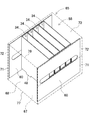
図11は複数個の仕切り部材34を連結して形成した仕切り体58を示す。 仕切り部材34は開口部59が面一となるように隣接する縦壁36と縦壁37とが接着され、さらに連結された仕切り部材34の両側には、フラップ38とフラップ39とを覆うように側板60が接着される。側板60の中央部には細長な孔部61が形成されており(図12を参照のこと。)、側板60は、この孔部61が孔部57に沿うように接着される。これらの仕切り部材34を連結して側板60を接着する作業は、機械を用いて行うことができる。なお、仕切り部材34の内部に仕切り板82(図13を参照のこと。)を設置して仕切り部材34の内部を仕切ることもできる。   FIG. 11 shows a partition body 58 formed by connecting a plurality of partition members 34. Adjacent vertical wall 36 and vertical wall 37 are bonded so that opening 59 is flush with partition member 34, and further, flap 38 and flap 39 are covered on both sides of connected partition member 34. The side plate 60 is bonded. An elongated hole 61 is formed at the center of the side plate 60 (see FIG. 12). The side plate 60 is bonded so that the hole 61 is along the hole 57. The operation | work which connects these partition members 34 and adhere | attaches the side plate 60 can be performed using a machine. Note that a partition plate 82 (see FIG. 13) may be installed inside the partition member 34 to partition the interior of the partition member 34.

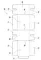
図14は仕切り体58が収納される収納箱65の展開図である。収納箱65は、展開された状態で、底壁67と、底壁67に連設される側壁68,69と、側壁68に連設される上壁70とを備えている。底壁67の両側部にはフラップ71が連設されており、上壁70の両側部にはフラップ72が連設されている。側壁68,69の両端部には各々フラップ73,74が連設されている。上壁70の端部には糊代77が設けられており、この糊代77は側壁69の端部に接着される。   FIG. 14 is a development view of the storage box 65 in which the partition body 58 is stored. The storage box 65 includes a bottom wall 67, side walls 68 and 69 connected to the bottom wall 67, and an upper wall 70 connected to the side wall 68 in the expanded state. A flap 71 is provided on both sides of the bottom wall 67, and a flap 72 is provided on both sides of the upper wall 70. Flaps 73 and 74 are connected to both end portions of the side walls 68 and 69, respectively. An adhesive margin 77 is provided at the end of the upper wall 70, and the adhesive margin 77 is bonded to the end of the side wall 69.

図15は仕切り体58が収納箱65に収納された状態の斜視図である。仕切り体58が収納箱65に収納されるときには、仕切り体58がたとえばブランク材の底壁67に載置される。このとき仕切り体58は、側板60がフラップ71の基端部側に向いた状態で載置される。この状態で側壁68,69が各々折曲線77,78で折り曲げられ、さらに上壁70が折曲線79で折り曲げられる。上壁70の糊代77が側壁69の端部に接着されて筒状に形成される。そして側壁68,69のフラップ73,74が折り曲げられ、さらに底壁67と上壁70とのフラップ71,72が折り曲げられて接着される。このように、収納箱65は仕切り体58が収納された状態で組み立てられる。   FIG. 15 is a perspective view of the partition body 58 stored in the storage box 65. When the partition body 58 is stored in the storage box 65, the partition body 58 is placed on the bottom wall 67 of a blank material, for example. At this time, the partition body 58 is placed in a state where the side plate 60 faces the base end side of the flap 71. In this state, the side walls 68 and 69 are bent at the folding lines 77 and 78, respectively, and the upper wall 70 is further bent at the folding line 79. A margin 77 of the upper wall 70 is bonded to the end of the side wall 69 to form a cylinder. The flaps 73 and 74 of the side walls 68 and 69 are bent, and the flaps 71 and 72 of the bottom wall 67 and the upper wall 70 are further bent and bonded. Thus, the storage box 65 is assembled in a state where the partition body 58 is stored.

収納箱65に収納された仕切り体58は、凸状に形成された側辺48と凸部44とが脚部を形成しており、この脚部が底壁67に当接している。仕切り体58の両側には側板60が接着されており、この側板60の端部が収納箱65の側壁68,69に当接している。これによって収納箱65が受けた衝撃が収納物に伝わることを緩和することができる。   In the partition body 58 stored in the storage box 65, the side 48 formed in a convex shape and the convex portion 44 form a leg portion, and the leg portion is in contact with the bottom wall 67. Side plates 60 are bonded to both sides of the partition body 58, and end portions of the side plates 60 are in contact with the side walls 68 and 69 of the storage box 65. Thereby, it is possible to mitigate the impact received by the storage box 65 from being transmitted to the stored items.

本発明の第3の実施形態について図面に基づいて説明する。図16に示すように、仕切り部材94は、展開された状態で底壁95と、底壁95の両端に連設される縦壁96と縦壁97とを備えている。縦壁96の両側部にはフラップ98が連設されており、縦壁97の両側部にはフラップ99が連設されている。   A third embodiment of the present invention will be described with reference to the drawings. As shown in FIG. 16, the partition member 94 includes a bottom wall 95 in a deployed state, and a vertical wall 96 and a vertical wall 97 that are connected to both ends of the bottom wall 95. A flap 98 is connected to both sides of the vertical wall 96, and a flap 99 is connected to both sides of the vertical wall 97.

図17は組み立てられた仕切り部材94の斜視図である。図16に示すブランク材は、底壁95の両端に連設された縦壁96と縦壁97とがそれぞれ折曲線101と102とで折り曲げられ、縦壁96と縦壁97とが対向するように断面がコの字状に形成される。フラップ98は折曲線103で折り曲げられ、フラップ99は折曲線104で折り曲げられる。そしてフラップ98とフラップ99とが接着されて仕切り部材94が形成される。これらの組み立て作業は、ブランク材に収納物を載置した状態で、製函機を用いて行うことができる。たとえばブランク材の縦壁96に収納物を載置した状態で組み立てて、仕切り部材94の組み立て作業が完了したときに収納物を仕切り部材94に収納することができる。   FIG. 17 is a perspective view of the assembled partition member 94. In the blank shown in FIG. 16, the vertical wall 96 and the vertical wall 97 connected to both ends of the bottom wall 95 are bent at the folding lines 101 and 102, respectively, so that the vertical wall 96 and the vertical wall 97 face each other. The cross section is formed in a U shape. The flap 98 is bent at the folding line 103, and the flap 99 is bent at the folding line 104. And the flap 98 and the flap 99 are adhere | attached, and the partition member 94 is formed. These assembling operations can be performed using a box making machine in a state where a stored item is placed on a blank material. For example, the stored items can be assembled in a state where the stored items are placed on the vertical wall 96 of the blank material, and the stored items can be stored in the partition member 94 when the assembly work of the partition member 94 is completed.

図18は複数個の仕切り部材94を連結して形成した仕切り体111を示す。 仕切り部材94は開口部112が面一となるように隣接する縦壁96と縦壁97とが接着され、さらに連結された仕切り部材94の両側には、フラップ99の上端と下端とを覆うように側板113(図19を参照のこと。)が接着される。これらの仕切り部材94を連結して側板113を接着する作業は、機械を用いて行うことができる。   FIG. 18 shows a partition body 111 formed by connecting a plurality of partition members 94. Adjacent vertical wall 96 and vertical wall 97 are bonded so that the opening 112 is flush with the partition member 94, and the upper and lower ends of the flap 99 are covered on both sides of the connected partition member 94. A side plate 113 (see FIG. 19) is adhered to the substrate. The operation | work which connects these partition members 94 and adhere | attaches the side plate 113 can be performed using a machine.

不図示の収納箱に収納された仕切り体111は、フラップ99の上端と下端とに接着された側板113の端部が収納箱の内面に当接する。これによって収納箱が外部から受けた衝撃が収納物に伝わることを緩和することができる。   In the partition body 111 stored in a storage box (not shown), the end portion of the side plate 113 bonded to the upper end and the lower end of the flap 99 comes into contact with the inner surface of the storage box. As a result, it is possible to mitigate the impact received from the outside by the storage box to the stored items.

本発明の精密機器用収納容器は、LED等の半導体素子の他、集積回路やインクカートリッジ等の精密機器、あるいは食品類や医薬品類等を収容する収納容器として好適に利用できる。   The storage container for precision devices of the present invention can be suitably used as a storage container for storing semiconductor devices such as LEDs, precision devices such as integrated circuits and ink cartridges, or foods and pharmaceuticals.

1,21…精密機器用収納容器
2,22,65…収納箱
3,23,58,111…仕切り体
4,4A,4B,4C,34,94…仕切り部材
5,24,35,67,95…底壁
6,7,36,37,96,97…縦壁
8,9,38,39,40,41,71,72,73,74,98,99…フラップ
5a,8a,47,57,61…孔部
5b,8b…切り欠き線
5c,8c,8e,16b,44…凸部
8d…凹部
10,11,12,13,50,51,54,55,78,79,101,102,103,104…折曲線
14,59,112…開口部
16…仕切り片
18…上部
19,20…隙間
25,68,69…側壁
26…本体部
27,82…仕切り板
28,29,30…空間
42,43…切り欠き
16a,48…側辺
60,113…側板
70…上壁
77…糊代
1, 21... Precision equipment storage containers 2, 22, 65 ... Storage boxes 3, 23, 58, 111 ... Partition bodies 4, 4 A, 4 B, 4 C, 34, 94 ... Partition members 5, 24, 35, 67, 95 ... bottom walls 6, 7, 36, 37, 96, 97 ... vertical walls 8, 9, 38, 39, 40, 41, 71, 72, 73, 74, 98, 99 ... flaps 5a, 8a, 47, 57, 61 ... holes 5b, 8b ... notch lines 5c, 8c, 8e, 16b, 44 ... projections 8d ... concaves 10, 11, 12, 13, 50, 51, 54, 55, 78, 79, 101, 102, 103, 104 ... folding lines 14, 59, 112 ... opening 16 ... partition piece 18 ... upper part 19, 20 ... gap 25, 68, 69 ... side wall 26 ... body part 27, 82 ... partition plates 28, 29, 30 ... space 42, 43 ... notches 16a, 48 ... side 60, 113 ... side 70 ... upper wall 77 ... margin

Claims (8)

収納箱と、
収納箱の内部に設置される仕切り体とを備えた精密機器用収納容器において、
仕切り体は、隣合わせに配置され収納物が収納される複数個の仕切り部材を備えており、
前記仕切り部材は、底壁と、底壁の両端から立ち上がる縦壁と、縦壁の両側部に連設され対向する縦壁の側部を接続するフラップとを備え、
前記フラップには、隣合わせに配置される仕切り部材のフラップに係合する第1の係合部と、隣合わせに配置される仕切り部材のフラップの係合部が係合する第1の被係合部とがフラップと一体に形成されており、
前記底壁には隣合わせに配置される仕切り部材の底壁に係合する第2の係合部と、隣合わせに配置される仕切り部材の底壁に設けられた係合部が係合する第2の被係合部が底壁と一体的に設けられていることを特徴とする精密機器用収納容器。
A storage box,
In the storage container for precision equipment provided with a partition body installed inside the storage box,
The partition body is provided with a plurality of partition members that are arranged next to each other and in which stored items are stored.
The partition member includes a bottom wall, a vertical wall that rises from both ends of the bottom wall, and a flap that is connected to both sides of the vertical wall and connects the opposing side walls of the vertical wall.
A first engaging portion that engages with a flap of a partition member that is disposed adjacent to the flap, and a first engaged portion that engages with an engagement portion of the flap of a partition member that is disposed adjacent to the flap. And is formed integrally with the flap,
A second engaging portion that engages with the bottom wall of the partition member disposed adjacent to the bottom wall and a second engaging portion provided on the bottom wall of the partition member disposed adjacent to the bottom wall engage with the bottom wall. The precision container is characterized in that the engaged portion is provided integrally with the bottom wall.
第1の係合部はフラップの基端部および/または先端部に連設された凸部であることを特徴とする請求項1に記載の精密機器用収納容器。   The precision instrument storage container according to claim 1, wherein the first engaging portion is a convex portion provided continuously to the proximal end portion and / or the distal end portion of the flap. 第1の被係合部はフラップの基端部に形成された孔部および/またはフラップの先端部に形成された凹部であることを特徴とする請求項1または2に記載の精密機器用収納容器。   3. The precision instrument storage according to claim 1, wherein the first engaged portion is a hole formed in a base end portion of the flap and / or a concave portion formed in a tip end portion of the flap. container. 第2の係合部は底壁に形成された舌片であることを特徴とする請求項1〜3のいずれか1項に記載の精密機器用収納容器。   The container for precision instruments according to any one of claims 1 to 3, wherein the second engaging portion is a tongue piece formed on the bottom wall. 第2の被係合部は底壁に形成された孔部であることを特徴とする請求項1〜4のいずれか1項に記載の精密機器用収納容器。   The precision instrument storage container according to any one of claims 1 to 4, wherein the second engaged portion is a hole formed in the bottom wall. 仕切り体の端部に位置する仕切り部材は前記第1の係合部が収納箱の内面に当接することを特徴とする請求項1〜5のいずれか1項に記載の精密機器用収納容器。   The storage container for precision equipment according to any one of claims 1 to 5, wherein the partition member positioned at an end of the partition body has the first engaging portion in contact with an inner surface of the storage box. 縦壁は底壁に向かって幅狭なテーパ状に形成されていることを特徴とする請求項1〜6のいずれか1項に記載の精密機器用収納容器。   The storage container for precision equipment according to any one of claims 1 to 6, wherein the vertical wall is formed in a tapered shape having a narrow width toward the bottom wall. 仕切り部材は、仕切り部材の内部を仕切る仕切り部材を備えていることを特徴とする請求項1〜7のいずれか1項に記載の精密機器用収納容器。   The storage container for precision equipment according to any one of claims 1 to 7, wherein the partition member includes a partition member that partitions the interior of the partition member.
JP2013207723A 2013-10-02 2013-10-02 Storage container for precision instrument Pending JP2015071438A (en)

Priority Applications (1)

Application Number Priority Date Filing Date Title
JP2013207723A JP2015071438A (en) 2013-10-02 2013-10-02 Storage container for precision instrument

Applications Claiming Priority (1)

Application Number Priority Date Filing Date Title
JP2013207723A JP2015071438A (en) 2013-10-02 2013-10-02 Storage container for precision instrument

Publications (1)

Publication Number Publication Date
JP2015071438A true JP2015071438A (en) 2015-04-16

Family

ID=53014141

Family Applications (1)

Application Number Title Priority Date Filing Date
JP2013207723A Pending JP2015071438A (en) 2013-10-02 2013-10-02 Storage container for precision instrument

Country Status (1)

Country Link
JP (1) JP2015071438A (en)

Citations (5)

* Cited by examiner, † Cited by third party
Publication number Priority date Publication date Assignee Title
JPS5441858U (en) * 1977-08-29 1979-03-20
JPS5951783U (en) * 1982-09-29 1984-04-05 日本電気ホームエレクトロニクス株式会社 Ring-shaped fluorescent lamp packaging equipment
JPS6190785U (en) * 1984-11-16 1986-06-12
JPH07300128A (en) * 1995-05-18 1995-11-14 Saitou Nojo:Kk Packaging box
JP2011068386A (en) * 2009-09-25 2011-04-07 Teikoku Seiyaku Co Ltd Partition structural body for packing box

Patent Citations (5)

* Cited by examiner, † Cited by third party
Publication number Priority date Publication date Assignee Title
JPS5441858U (en) * 1977-08-29 1979-03-20
JPS5951783U (en) * 1982-09-29 1984-04-05 日本電気ホームエレクトロニクス株式会社 Ring-shaped fluorescent lamp packaging equipment
JPS6190785U (en) * 1984-11-16 1986-06-12
JPH07300128A (en) * 1995-05-18 1995-11-14 Saitou Nojo:Kk Packaging box
JP2011068386A (en) * 2009-09-25 2011-04-07 Teikoku Seiyaku Co Ltd Partition structural body for packing box

Similar Documents

Publication Publication Date Title
US20050161366A1 (en) Packaging material provided with cushioning members
US20160221711A1 (en) Packaging box
KR101463269B1 (en) Packing Box Integrated With Handle
JP2015071438A (en) Storage container for precision instrument
JP2008013218A (en) Packing box and spacer for packing
JP2009018858A (en) Partition unit
JP4746446B2 (en) Packing interior material
JP2015074469A (en) Box used also as stacking tray
KR101876323B1 (en) Packing case for carrying parts
JP3183027U (en) Partition material
JP7176452B2 (en) packaging box
JP6604285B2 (en) tray
JP5935608B2 (en) Stackable carry cartons
JP2009184698A (en) Packaging box with cushioning-partition
JP6339390B2 (en) Storage box
JP2013039963A (en) Cushioning material made of corrugated board
JP3206163U (en) Packing box
JP2005075410A (en) Packing material and method
JP3118858U (en) Pack storage box
JP6653630B2 (en) Partition for storing long objects
JP2016068984A (en) Packing box
JP2007039126A (en) Packing box and package
JP2015209227A (en) Packing partition material
JP2022109557A (en) tray
JP2022043667A (en) Packaging box

Legal Events

Date Code Title Description
A131 Notification of reasons for refusal

Free format text: JAPANESE INTERMEDIATE CODE: A131

Effective date: 20150106

A02 Decision of refusal

Free format text: JAPANESE INTERMEDIATE CODE: A02

Effective date: 20150512