JP2015071237A - Coating film transfer tool - Google Patents
Coating film transfer tool Download PDFInfo
- Publication number
- JP2015071237A JP2015071237A JP2013207190A JP2013207190A JP2015071237A JP 2015071237 A JP2015071237 A JP 2015071237A JP 2013207190 A JP2013207190 A JP 2013207190A JP 2013207190 A JP2013207190 A JP 2013207190A JP 2015071237 A JP2015071237 A JP 2015071237A
- Authority
- JP
- Japan
- Prior art keywords
- transfer
- coating film
- tape
- belt
- head
- Prior art date
- Legal status (The legal status is an assumption and is not a legal conclusion. Google has not performed a legal analysis and makes no representation as to the accuracy of the status listed.)
- Granted
Links
Images
Landscapes
- Adhesive Tape Dispensing Devices (AREA)
Abstract
【課題】転写テープの蛇行を防止することができる塗膜転写具の提供。
【解決手段】基材テープに塗膜を設けた転写テープの塗膜を被転写体に転写するための塗膜転写具であって、転写テープを繰出す繰出し部と、転写テープを被転写体に押圧して塗膜を被転写体に転写する転写押圧部を有する転写ヘッドと、転写後の基材テープを巻き取る巻取り部が筐体に収納され、転写ヘッド及び/又は筐体に設けられた転写押圧部を含む複数のガイド部にベルトが掛けまわされ、転写テープの塗膜が設けられた面の反対側の面がベルトに掛けまわされ、ベルトの転写テープと接する面は高摩擦材料からなり、転写押圧部を被転写体に押圧して塗膜を転写すると、転写テープの走行に伴ってベルトが転写ヘッドのまわりを回転することを特徴とする塗膜転写具。
【選択図】図1Provided is a coating film transfer tool capable of preventing meandering of a transfer tape.
A coating film transfer tool for transferring a coating film of a transfer tape having a coating film on a base tape to a transfer target, a feeding portion for feeding the transfer tape, and the transfer tape on the transfer target A transfer head having a transfer pressing part that presses the film onto the transfer target and a winding part that winds the base tape after transfer is housed in the housing, and is provided in the transfer head and / or the housing. The belt is wound around a plurality of guide parts including the transferred transfer pressing part, the surface opposite to the surface on which the coating film of the transfer tape is provided is wrapped around the belt, and the surface of the belt contacting the transfer tape is highly frictional. A coating film transfer tool comprising a material, wherein the belt rotates around the transfer head as the transfer tape travels when the transfer pressing portion is pressed against the transfer target to transfer the coating film.
[Selection] Figure 1
Description
本発明は、基材テープに修正用塗膜、接着用粘着剤、装飾用塗膜等を設けた転写テープを被転写体に転写するために用いる塗膜転写具に関する。 The present invention relates to a coating film transfer tool used for transferring a transfer tape having a base film tape provided with a correction coating film, an adhesive for adhesion, a decorative coating film, and the like to a transfer target.
このような塗膜転写具では、基材テープ上に塗膜が塗布された転写テープが、繰出しコアから繰り出され、転写ヘッドで転写テープを被転写体に押圧することによって、塗膜が転写テープから被転写体に転写され、残った基材テープが巻取りコアに巻き取られるようになっている。 In such a coating film transfer tool, the transfer tape with the coating film coated on the base tape is fed out from the feeding core, and the transfer tape is pressed against the transfer object by the transfer head, whereby the coating film is transferred to the transfer tape. Then, the remaining base tape is transferred to the transfer body and wound around the winding core.
修正用塗膜、接着用粘着剤、装飾用塗膜等を設けた転写テープの基材テープは、基材から塗膜を剥離して転写するために、両面に離型処理が施されている。転写テープがコアに巻き回された時に塗膜が貼り付かないように、特に塗膜と反対側の背面は、より強力な離型処理が施されている。このため、転写テープの背面は、他部品と接触した場合の摩擦係数が小さく、滑りやすいものとなっている。 The base tape of the transfer tape provided with a coating film for correction, an adhesive for adhesion, a coating film for decoration, etc. is subjected to mold release treatment on both sides in order to peel and transfer the coating film from the base material. . In order to prevent the coating film from sticking when the transfer tape is wound around the core, the back surface on the side opposite to the coating film is subjected to a stronger release treatment. For this reason, the back surface of the transfer tape has a small coefficient of friction when in contact with other parts, and is slippery.
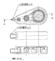
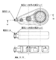
塗膜転写具の転写ヘッドとしては、特許文献1のような、転写テープを被転写体に押圧して転写テープから塗膜を被転写体に転写する転写押圧部がヘラ状となった転写ヘッド(図3)と、特許文献2のような、転写ロールを用いた転写ヘッド(図4)が、従来から多く使用されている。ヘラ状の転写ヘッドでは、転写テープの背面がヘラの上を滑って走行しているため、転写テープの走行方向に対して垂直な横方向にもヘラに対して滑り易い。このため、ヘラ状の転写ヘッドで塗膜を転写すると、転写テープはヘラの上を左右に滑って、蛇行し、塗膜を真っ直ぐに被転写体に転写することが困難であった。
As a transfer head of a coating film transfer tool, as in
また、転写ヘッドに転写ロールを用いた転写ヘッドでは、転写ヘッドで転写テープを押圧して塗膜を被転写体に転写すると、転写テープの走行に伴って転写ロールが回転するので、ヘラ状の転写ヘッドに比べると転写テープの転写ロール上の蛇行は小さくなる。しかしながら、転写テープが転写ロールと接触して走行する距離は短いので、転写ロールを用いた転写ヘッドでも、転写テープの蛇行を小さくする手段としては十分なものではなかった。転写ロールの外径を大きくすれば、転写テープが転写ロールと接触して走行する距離が長くなるので、転写テープの蛇行を防止する効果が大きくなるが、転写ロールの外径を大きくすると、塗膜転写具自体が大きくなるほか、転写位置が見難くなるなどの問題もあり、転写テープの蛇行を小さくする手段としては十分なものではなかった。 In addition, in a transfer head using a transfer roll as the transfer head, when the transfer tape is pressed by the transfer head and the coating film is transferred to the transfer object, the transfer roll rotates as the transfer tape travels. The meandering on the transfer roll of the transfer tape is smaller than that of the transfer head. However, since the distance that the transfer tape travels in contact with the transfer roll is short, even a transfer head using the transfer roll is not sufficient as a means for reducing the meandering of the transfer tape. Increasing the outer diameter of the transfer roll increases the distance that the transfer tape travels in contact with the transfer roll, thereby increasing the effect of preventing the meandering of the transfer tape. In addition to an increase in the size of the film transfer tool itself, there are also problems such as difficulty in seeing the transfer position.
このような転写押圧部での転写テープの蛇行を小さくする手段として、転写ロールの表面をゴムなどの摩擦係数の大きな材質とした転写ヘッドがある。転写ロールの表面の摩擦係数を大きくすることによって、転写ロール上を転写テープが左右に滑り難くし、転写押圧部での転写テープの蛇行を小さくすることができる。しかしながら、転写ロールの表面の摩擦係数を大きくした転写ヘッドを用いても、転写押圧部のみで転写テープの蛇行を防止しているので、転写押圧部に到達する前にすでに転写テープの蛇行が始まっている場合などには、転写テープの蛇行を防止することができず、転写テープの蛇行防止の手段としては不十分であった。 As a means for reducing the meandering of the transfer tape at such a transfer pressing portion, there is a transfer head in which the surface of the transfer roll is made of a material having a large friction coefficient such as rubber. By increasing the coefficient of friction of the surface of the transfer roll, it is difficult for the transfer tape to slide left and right on the transfer roll, and the meandering of the transfer tape at the transfer pressing portion can be reduced. However, even if a transfer head with a large friction coefficient on the surface of the transfer roll is used, the transfer tape is prevented from meandering only by the transfer pressing portion, so that the transfer tape starts to meander before reaching the transfer pressing portion. In such a case, the meandering of the transfer tape could not be prevented, which was insufficient as a means for preventing the meandering of the transfer tape.
転写テープが蛇行すると、転写テープが転写ヘッドに対して、横方向にずれ、転写テープをガイドする転写ヘッドのテープ規制部材に転写テープが強く接触する。転写テープがテープ規制部材に強く接触すると、転写テープ端部が折れたものや、転写テープ端部の塗膜が傷付いたものが発生する。このような端部が折れた転写テープや端部の塗膜が傷付いた転写テープを使用すると、転写された塗膜は表面にスジが入ったものや、端部が傷付いたものとなるという問題がある。また、転写テープが蛇行することにより、転写ヘッド自体も蛇行しやすくなるために、使用者が転写ヘッドを真っ直ぐに引くことが難しくなる。使用者が転写しようと意図した方向に対して、転写ヘッドが斜め方向に進み、転写した塗膜が蛇行したものとなるという問題もある。 When the transfer tape meanders, the transfer tape is displaced laterally with respect to the transfer head, and the transfer tape comes into strong contact with the tape regulating member of the transfer head that guides the transfer tape. When the transfer tape comes into strong contact with the tape regulating member, the transfer tape end portion is broken or the transfer tape end portion is damaged. If you use a transfer tape that has a broken edge or a scratched coating film on the edge, the transferred coating film will have streaks on the surface or scratched edges. There is a problem. Further, since the transfer tape meanders, the transfer head itself can easily meander, and it is difficult for the user to pull the transfer head straight. There is also a problem that the transfer head advances in an oblique direction with respect to the direction intended to be transferred by the user, and the transferred coating film meanders.
本発明は前記のような従来の塗膜転写具の問題点に鑑みてなされたものであって、本発明が解決しようとする課題は、転写ヘッドを大きくすることなく、転写テープの蛇行を防止することができる転写ヘッドを有する塗膜転写具の提供である。 The present invention has been made in view of the problems of the conventional coating film transfer tool as described above, and the problem to be solved by the present invention is to prevent meandering of the transfer tape without enlarging the transfer head. It is providing the coating-film transfer tool which has a transfer head which can do.
第1発明は、基材テープに塗膜を設けた転写テープの前記塗膜を被転写体に転写するための塗膜転写具であって、前記転写テープを繰出す繰出し部と、前記転写テープを前記被転写体に押圧して前記塗膜を前記被転写体に転写する転写押圧部を有する転写ヘッドと、転写後の前記基材テープを巻き取る巻取り部が筐体に収納され、前記転写ヘッド及び/又は前記筐体に設けられた前記転写押圧部を含む複数のガイド部にベルトが掛けまわされ、転写テープの塗膜が設けられた面の反対側の面が前記ベルトに掛けまわされ、前記ベルトの前記転写テープと接する面は高摩擦材料からなり、前記転写押圧部を前記被転写体に押圧して前記塗膜を転写すると、前記転写テープの走行に伴って前記ベルトが前記転写ヘッドのまわりを回転することを特徴とする塗膜転写具である。 1st invention is the coating-film transfer tool for transferring the said coating film of the transfer tape which provided the coating film in the base material tape to a to-be-transferred body, Comprising: The feeding part which pays out the said transfer tape, The said transfer tape A transfer head having a transfer pressing portion that presses the transfer member onto the transfer target body and transfers the coating film to the transfer target member, and a winding portion that winds up the base tape after transfer is housed in a housing. A belt is hung on a plurality of guide portions including the transfer pressing portion provided on the transfer head and / or the casing, and a surface opposite to the surface on which the coating film of the transfer tape is provided is hung on the belt. The surface of the belt that comes into contact with the transfer tape is made of a high-friction material, and when the transfer pressing portion is pressed against the transfer target and the coating film is transferred, the belt is moved along with the running of the transfer tape. Specially rotating around the transfer head A coating film transfer tool according to.
第2発明は、前記高摩擦材料が、天然ゴム、合成ゴム、又はこれらを含む混合物からなることを特徴とする第1発明に記載の塗膜転写具である。 A second invention is the coating film transfer tool according to the first invention, wherein the high friction material is made of natural rubber, synthetic rubber, or a mixture containing these.
第3発明は、前記ベルトの前記ガイド部と接する面は滑性材料からなり、又は滑性処理が施されていることを特徴とする第1又は第2発明に記載の塗膜転写具である。 A third aspect of the present invention is the coating film transfer tool according to the first or second aspect, wherein the surface of the belt that is in contact with the guide portion is made of a slippery material or is subjected to a slippery process. .
第4発明は、前記ベルトが前記ガイド部に回転可能保持された複数のロールに掛けまわされたことを特徴とする第1又は第2発明に記載の塗膜転写具である。 A fourth invention is the coating film transfer tool according to the first or second invention, wherein the belt is wound around a plurality of rolls rotatably held by the guide portion.
本発明の塗膜転写具では、転写テープの背面とベルトとの摩擦力によって、ベルトが転写テープの走行に伴い、転写ヘッドのまわりを回転する。転写テープはベルトと接して走行し、転写テープの背面とベルトとの摩擦力が大きいので、転写テープはベルトに対して滑り難い。このため、転写テープはベルトに対して蛇行しない。また、ベルトは転写ヘッド部分の短い輪であるので、ベルトは転写ヘッドのまわりを転写ヘッドに対して、蛇行せずに回転する。この結果、転写テープは転写ヘッドに対して蛇行せず、真っ直ぐに塗膜を転写することができる。 In the coating film transfer tool of the present invention, the belt rotates around the transfer head as the transfer tape runs due to the frictional force between the back surface of the transfer tape and the belt. Since the transfer tape runs in contact with the belt and the frictional force between the back surface of the transfer tape and the belt is large, the transfer tape is difficult to slide against the belt. For this reason, the transfer tape does not meander with respect to the belt. Further, since the belt is a short ring of the transfer head portion, the belt rotates without meandering around the transfer head with respect to the transfer head. As a result, the transfer tape does not meander with respect to the transfer head, and the coating film can be transferred straight.
転写ヘッドの転写押圧部だけではなく、転写押圧部の前後にも転写テープの蛇行を防止する手段を設ければ、転写押圧部での転写テープの蛇行をより確実に防止することができる。従来技術として転写ロールの表面の摩擦係数を大きくした転写ヘッドがあるように、転写テープと接触する面の摩擦係数を大きくすることが転写テープの蛇行防止に効果を発揮する。しかしながら、ヘラ状ヘッドの転写押圧部のように転写テープとともに移動しない部材の摩擦係数を大きなものとすると、転写テープの走行抵抗が大きくなって、転写テープの走行不良の原因となる。そこで、本発明者は、転写テープと接触して転写テープの走行に伴って走行する部材を転写ヘッドに設けることにより、転写テープの走行抵抗を出来る限り大きくすることなく、転写テープの蛇行をより確実に防止できることを見出し、本発明をするに至った。 If means for preventing meandering of the transfer tape is provided not only at the transfer pressing part of the transfer head but also before and after the transfer pressing part, meandering of the transfer tape at the transfer pressing part can be more reliably prevented. As a conventional technique, there is a transfer head in which the friction coefficient of the surface of the transfer roll is increased. Increasing the friction coefficient of the surface in contact with the transfer tape is effective in preventing the meandering of the transfer tape. However, if the coefficient of friction of a member that does not move with the transfer tape, such as the transfer pressing portion of the spatula-shaped head, is increased, the running resistance of the transfer tape is increased, causing the transfer tape to run poorly. Therefore, the present inventor has provided a member that contacts the transfer tape and travels as the transfer tape travels, so that the transfer tape can be more meandered without increasing the travel resistance of the transfer tape as much as possible. The inventors have found that it can be surely prevented and have come to make the present invention.
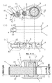
本発明の第1実施形態である塗膜転写具Aを図1に示す。図1(a)はカバーを除去した状態の塗膜転写具Aの正面図であり、図1(b)は塗膜転写具Aのカバーをセットした状態の底面図である。図1(c)は、図1(a)のM−M断面図である。 The coating film transfer tool A which is 1st Embodiment of this invention is shown in FIG. FIG. 1A is a front view of the coating film transfer tool A with the cover removed, and FIG. 1B is a bottom view of the coating film transfer tool A with the cover set. FIG.1 (c) is MM sectional drawing of Fig.1 (a).
塗膜転写具Aは、図1に示すようにケ−ス1とカバー2からなる筐体、塗膜を塗布した転写テ−プTを巻きまわした繰出しコア3、塗膜を紙等の被転写体に転写する転写ヘッド4、塗膜を転写した後の基材テ−プT1を巻取る巻取りコア5、繰出しコア3の回転を巻取りコア5に伝えるOリング6、及び転写ヘッド4に掛けまわしたベルト7から構成されるものであるが、これに限定されるものではなく、転写テープの繰出し部と、塗膜を転写した残りの基材テープを巻取る巻取り部を有し、ベルトを掛けまわした転写ヘッドにて、転写テープから塗膜を転写する形態のものであれば、どのような形態のものであってもよい。
As shown in FIG. 1, the coating film transfer tool A is composed of a casing made up of a
塗膜転写具Aの転写ヘッド4には、図1の(a)に示すように、転写押圧部41を構成するガイド部48が設けられ、ケース1には転写ヘッド4を固定する固定ボス11が設けられる。ベルト7の内周面は、このガイド部48ともう1端のガイド部の役割を果たす固定ボス11に掛けまわされる。
As shown in FIG. 1A, the
転写テープTはベルト7の上から、転写ヘッド4に掛けまわされる。転写テープTの背面は、繰出しコア3から繰出された後、固定ボス11上から転写押圧部41を通過し、再び固定ボス11上に戻るまでの間、ベルト7の外周と接触する。
The transfer tape T is wound around the
ベルト7は、天然ゴム、合成ゴム、又はこれらを含む混合物であるゴムや、ポリエチレンテレフタレート系ポリエステル、ポリエチレンナフタレート系ポリエステルなどのプラスチックフィルムから選ばれる材料を環状ダイから溶融押出しして、薄板の輪としたものなどを使用することができる。 The belt 7 is made by melting and extruding a material selected from natural rubber, synthetic rubber, or a rubber containing a mixture thereof, or a plastic film such as polyethylene terephthalate polyester or polyethylene naphthalate polyester from an annular die. Can be used.
ベルト7に、ポリエチレンテレフタレート系ポリエステルなどのプラスチックフィルムを使用する場合には、転写テープと接するベルト7の外周面には天然ゴム、合成ゴム、又はこれらを含む混合物からなる高摩擦材料の層を設ける。高摩擦材料の層を設ける方法としては、未加硫ゴムを加硫し、加硫ゴムとプラスチックフィルムを接合することにより得ることができるほか、プラスチックフィルムにゴム材料溶液をバーコーティング法等にて塗布、乾燥して形成することができる。加硫にて高摩擦材料層を設ける場合の、ゴム材料としては、天然ゴム、シリコーンゴム、エチレンプロピレンゴム、アクリロニトリルブタジエンゴム、スチレンブタジエンゴム、クロロプレンゴム、アクリルゴム、フッ素ゴムおよびポリウレタンゴム等が例示される。また、塗布、乾燥して形成する高摩擦材料層を設ける場合のゴム材料としては熱可塑性のエラストマーが好適であり、ポリエステル系、ポリアミド系およびポリオレフィン系の熱可塑性エラストマーが例示される。 When a plastic film such as polyethylene terephthalate polyester is used for the belt 7, a layer of a high friction material made of natural rubber, synthetic rubber, or a mixture containing these is provided on the outer peripheral surface of the belt 7 in contact with the transfer tape. . As a method of providing a layer of a high friction material, it can be obtained by vulcanizing unvulcanized rubber and bonding the vulcanized rubber and a plastic film. It can be formed by coating and drying. Examples of rubber materials when a high friction material layer is provided by vulcanization include natural rubber, silicone rubber, ethylene propylene rubber, acrylonitrile butadiene rubber, styrene butadiene rubber, chloroprene rubber, acrylic rubber, fluoro rubber, and polyurethane rubber. Is done. In addition, a thermoplastic elastomer is suitable as a rubber material when a high friction material layer formed by coating and drying is provided, and examples thereof include polyester-based, polyamide-based, and polyolefin-based thermoplastic elastomers.
高摩擦材料層の厚みは、100〜500μmの範囲内が好ましい。さらに好ましくは、200〜300μmの範囲である。100μm未満になると、転写テープとの摩擦係数が小さくなり、500μmを超えるとベルトの剛性が大きくなり、直径が小さいガイド部48の外径に確実に沿うことができず、転写ヘッド周りをスムースに回転できなくなる。
The thickness of the high friction material layer is preferably in the range of 100 to 500 μm. More preferably, it is the range of 200-300 micrometers. If it is less than 100 μm, the coefficient of friction with the transfer tape decreases, and if it exceeds 500 μm, the rigidity of the belt increases, and the outer diameter of the
ベルト7の転写テープと接する面は、天然ゴム、合成ゴム、又はこれらの混合物などのプラスチックフィルムなどに比べて表面の摩擦係数が大きい材料から作られるので、転写テープTの背面との間でも大きな摩擦力が発生する。このため、固定ボス11上から転写押圧部41を通過し再び固定ボス11上に戻るまでの間で、ベルト7と接触している転写テープTはベルト7に対してほとんど走行方向の横方向にずれることなく、ベルト7とともに走行する。
Since the surface of the belt 7 in contact with the transfer tape is made of a material having a surface friction coefficient larger than that of a plastic film such as natural rubber, synthetic rubber, or a mixture thereof, it is large even between the back surface of the transfer tape T. A frictional force is generated. For this reason, the transfer tape T in contact with the belt 7 is almost in the lateral direction with respect to the belt 7 until it passes through the
一方、ベルト7のガイド部48、固定ボス11と接触する側の面は、シリコーン樹脂やフッ素樹脂などから選ばれる滑性材料が塗布された滑性層が設けられ、ガイド部48、固定ボス11に対して滑りやすくなっている。滑性層の材質、厚みは、転写テープTの背面の離系処理と同様とすることが、好ましい。
On the other hand, the surface of the belt 7 on the side in contact with the
ベルト7に天然ゴムなどのゴムを使用する場合には、ガイド部48と固定ボス11に掛けまわされたときに、ベルト7には弛みがなく、生じる伸びが小さいことが好ましい。ガイド部48と固定ボス11に掛けまわされたときのベルト7の伸びは、ベルト7の内周長の3%以内が好ましく、1.5%以内がより好ましい。ベルト7の伸びが3%を超えると、ベルト7がガイド部48と固定ボス11を押す力が大きくなり、ベルト7が転写ヘッド4の周りをスムースに回転しない。
When rubber such as natural rubber is used for the belt 7, it is preferable that the belt 7 has no slack when it is wound around the
ベルト7に、ポリエチレンテレフタレート系ポリエステルなどのプラスチックフィルムを使用する場合には、ベルト7がほとんど弾性変形しないので、弛みなくガイド部48と固定ボス11に掛けまわすことが困難である。よって、ベルト7に張力を付加する機構を設けることが好ましい。張力を付加する機構の図示は省略するが、ケースが弾性変形することにより、ベルトの内周面を外周方向へ押してベルト7に張力を付加する機構などを用いることができる。
When a plastic film such as polyethylene terephthalate polyester is used for the belt 7, the belt 7 hardly deforms elastically, so that it is difficult to hang around the
ベルト7がゴムである場合のベルト7の厚みは、0.5mm以上1.5mm以下が好ましく、0.8mm以上1.2mm以下がより好ましい。0.5mm未満になると、走行時にベルト7が伸び縮みし、転写ヘッド周りをスムースに回転できなくなる。一方、1.5mmを超えると、ベルト7剛性が大きくなり、直径が小さいガイド部48の外径に確実に沿うことができず、転写ヘッド周りをスムースに回転できなくなる。
When the belt 7 is rubber, the thickness of the belt 7 is preferably 0.5 mm or more and 1.5 mm or less, and more preferably 0.8 mm or more and 1.2 mm or less. If it is less than 0.5 mm, the belt 7 expands and contracts during running, and the periphery of the transfer head cannot be smoothly rotated. On the other hand, if it exceeds 1.5 mm, the rigidity of the belt 7 increases, and it is impossible to reliably follow the outer diameter of the
ベルト7に、ポリエチレンテレフタレート系ポリエステルなどのプラスチックフィルムを使用する場合には、プラスチックフィルムの厚みは、0.03mm以上0.2mm以下が好ましく、0.08mm以上0.15mm以下がより好ましい。0.03mm未満になると、ベルト7の製作と取り扱いが困難になる。一方、0.2mmを超えると、ベルト7剛性が大きくなり、直径が小さいガイド部48の外径に確実に沿うことができず、転写ヘッド周りをスムースに回転できなくなる。
When a plastic film such as polyethylene terephthalate polyester is used for the belt 7, the thickness of the plastic film is preferably 0.03 mm or more and 0.2 mm or less, more preferably 0.08 mm or more and 0.15 mm or less. If it is less than 0.03 mm, it is difficult to manufacture and handle the belt 7. On the other hand, if it exceeds 0.2 mm, the rigidity of the belt 7 is increased, and the outer diameter of the
図1(b)に示すように、塗膜転写具Aの転写ヘッドの左右両側には、転写テープTの蛇行を防止するテープ規制部42が設けられている。また、ケース1とカバー2にも、転写テープTの蛇行を防止するケース内面12とカバー内面22が設けられている。ベルト7の幅は、この左右両側のテープ規制部42の間隔、及びケース内面12とカバー内面22の間隔(以後、内面間の間隔と言う)よりも小さく、テープ規制部42の間隔、及び内面間の間隔とベルト7の幅の寸法差は、0.1mm以上0.3mm以下であることが好ましく、0.1mm以上0.2mm以下であることがより好ましい。テープ規制部42の間隔、及び内面間の間隔とベルト7の幅の寸法差が小さく設計されることによって、ベルト7は転写ヘッド4に対して蛇行せず、真っ直ぐに転写ヘッドのまわりを回転することができる。
As shown in FIG. 1B,
上記のように、ガイド部48と固定ボス11に掛けまわされたときの、ベルト7に生じる伸びを小さくし、テープ規制部42の間隔、及び内面間の間隔とベルト7の幅の寸法差も小さくすることで、ベルト7は転写ヘッド上を蛇行することなく、真っ直ぐに走行する。また、ベルト7と接触している転写テープTはベルト7に対してほとんど走行方向の横方向にずれることなく、ベルト7とともに走行する。よって、転写テープTも転写ヘッドに対して蛇行することなく、真っ直ぐに走行することができる。
As described above, the elongation generated in the belt 7 when hung on the
転写テープTの幅は、ベルト7の幅に比べて小さく、転写テープTの幅とベルト7の幅の寸法差は、0.1mm以上0.3mm以下であることが好ましく、0.1mm以上0.2mm以下であることがより好ましい。転写テープTの幅とベルト7の幅の寸法差が0.3mmを超えると、転写ヘッド4のテープ規制部42間の間隔、及び内面間の間隔に比べて、転写テープTの幅が小さくなり、テープ規制部42、及びケース内面12とカバー内面22による転写テープTの蛇行防止の効果が小さくなる。転写テープTの幅とベルト7の幅の寸法差が0.1mm未満になると、転写テープTの端部がベルト7上から脱落し易くなり、転写テープT端部の塗膜が被転写体に転写されずに、転写不良となり易くなる。
The width of the transfer tape T is smaller than the width of the belt 7, and the dimensional difference between the width of the transfer tape T and the width of the belt 7 is preferably 0.1 mm or more and 0.3 mm or less, and preferably 0.1 mm or more and 0. More preferably, it is 2 mm or less. When the dimensional difference between the width of the transfer tape T and the width of the belt 7 exceeds 0.3 mm, the width of the transfer tape T becomes smaller than the distance between the
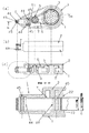
本発明の実施形態である塗膜転写具Bを図2に示す。図2(a)はカバーを除去した状態の塗膜転写具Bの正面図であり、図2(b)は塗膜転写具Bのカバーをセットした状態の底面図である。図2(c)は、図2(a)のM−M断面図である。 The coating film transfer tool B which is embodiment of this invention is shown in FIG. 2A is a front view of the coating film transfer tool B with the cover removed, and FIG. 2B is a bottom view of the coating film transfer tool B with the cover set. FIG.2 (c) is MM sectional drawing of Fig.2 (a).
塗膜転写具Bは、別部材の転写ヘッド4を有さず、ケース1に直接設けられた3本のロール軸45に回転可能にロール44が保持されており、この3本のロール44上にベルト7が掛けまわされていること以外は、塗膜転写具Aと同様である。
The coating film transfer tool B does not have the
塗膜転写具Bのケース1には、図2の(a)に示すように、転写押圧部41と、転写押圧部41と三角形状を成す2箇所に、3個のロール44を回転可能に保持するロール軸45が設けられる。塗膜転写具Bの転写ヘッドに相当する部分は、3箇所のロール軸45にロール44を装着し、3箇所のロール44にベルト7を掛けまわし、さらにベルト7の外側に転写テープTを掛けまわしたのちに、カバー2を装着することによって、組立てられる構造となっている。
In the
塗膜転写具Bのカバー2には、ケース1のロール軸45が設けられた場所に相当する位置に穴が設けられており、ケース1にカバー2を装着するとロール軸45の先端がカバー2の穴に挿入され、ロール44はケース1とカバー2の両方で回転可能に支持された状態となる。また、ベルト7が装着される箇所のケース1とカバー2の内面間の間隔は、塗膜転写具Aの転写ヘッドのテープ規制部42と同様に、ベルト7の幅よりも大きく、内面間の間隔とベルト7の幅の寸法差は、0.1mm以上0.3mm以下であることが好ましく、0.1mm以上0.2mm以下であることがより好ましい。内面の間隔とベルト7の幅の寸法差が小さく設計されることによって、ベルト7はケース1とカバー2に対して蛇行せずに、3本のロール44のまわりを回転する。
The
ベルト7に天然ゴムなどのゴムを使用する場合には、3本のロール44に掛けまわされたときに、ベルト7には弛みがなく、生じる伸びが小さいことが好ましい。3本のロール44に掛けまわされたときのベルト7の伸びは、ベルト7の内周長の0.5%以上3%以下が好ましく、0.5%以上1.5%以下がより好ましい。ベルト7の伸びが0.5%未満になると、ベルトが弛んでスムースに回転しなくなる。また、ベルト7の伸びが3%を超えると、ベルト7がロール44を押す力が大きくなり、ベルト7がスムースに回転しない。
When rubber such as natural rubber is used for the belt 7, it is preferable that the belt 7 has no slack when it is wound around the three rolls 44, and the resulting elongation is small. The elongation of the belt 7 when it is wound around the three rolls 44 is preferably 0.5% or more and 3% or less of the inner peripheral length of the belt 7, and more preferably 0.5% or more and 1.5% or less. When the elongation of the belt 7 is less than 0.5%, the belt is loosened and does not rotate smoothly. If the elongation of the belt 7 exceeds 3%, the force with which the belt 7 presses the
ベルト7に、ポリエチレンテレフタレート系ポリエステルなどのプラスチックフィルムを使用する場合には、塗膜転写具Aと同様に、ベルト7に張力を付加する機構を設けることが好ましい。張力を付加する機構の図示は省略するが、ケースが弾性変形することにより、前記3本のロールのうちの1本がベルトの内周面を外周方向へ押してベルト7に張力を付加する機構が好ましい。ロールがベルトを押すことにより、ベルト7の走行抵抗の上昇を極力小さくすることができる。 When a plastic film such as polyethylene terephthalate polyester is used for the belt 7, it is preferable to provide a mechanism for applying tension to the belt 7, as with the coating film transfer tool A. Although the illustration of the mechanism for applying the tension is omitted, there is a mechanism in which one of the three rolls pushes the inner peripheral surface of the belt in the outer peripheral direction to apply the tension to the belt 7 by elastic deformation of the case. preferable. When the roll presses the belt, the increase in running resistance of the belt 7 can be minimized.
塗膜転写具Bのベルト7は、塗膜転写具Aと同様に表面の摩擦係数が大きい材料から作られるので、転写テープTの背面との間でも大きな摩擦力が発生する。このため、ベルト7と接触している間、転写テープTはベルト7に対してほとんど走行方向の横方向にずれることなく、ベルト7とともに走行する。 Since the belt 7 of the coating film transfer tool B is made of a material having a large surface friction coefficient like the coating film transfer tool A, a large frictional force is generated between the belt 7 and the back surface of the transfer tape T. For this reason, while being in contact with the belt 7, the transfer tape T travels with the belt 7 without being substantially displaced laterally with respect to the belt 7.
塗膜転写具Aでは、ベルト7のガイド部48、固定ボス11と接触する側の面に滑性層が設けたが、塗膜転写具Bでは、ロール44がベルトの走行に伴って回転するので、ベルト7のロール44と接触する面に滑性層を設ける必要はない。
In the coating film transfer tool A, a slipping layer is provided on the surface of the belt 7 that comes into contact with the
図2(a)に示すように、塗膜転写具Bでは、繰出しコアから繰出された転写テープTの背面が、ロール44上のベルト7と接触した後、転写押圧部41を通リ反対側のロール44上を通過するまで、ベルト7と接触した状態で走行する。塗膜転写具Bも、塗膜転写具Aと同様に、転写テープTの背面とベルト7が接触している距離が長いので、転写テープTの蛇行を防止する効果が大きい。
As shown in FIG. 2A, in the coating film transfer tool B, after the back surface of the transfer tape T fed from the feeding core comes into contact with the belt 7 on the
A、B :塗膜転写具
T :転写テープ
T1 :基材テープ
1 :ケース
11 :固定ボス
12 :ケース内面
2 :カバー
22 :カバー内面
3 :繰出しコア
4 :転写ヘッド
5 :巻取りコア
6 :Oリング
7 :ベルト
41 :転写押圧部
42 :テープ規制部
44 :ロール
45 :ロール軸
48 :ガイド部
A, B: Coating film transfer tool
T: Transfer tape T1: Base tape 1: Case 11: Fixed boss 12: Case inner surface
2: Cover 22: Cover inner surface 3: Feeding core 4: Transfer head 5: Winding core 6: O-ring
7: Belt 41: Transfer pressing part 42: Tape regulating part 44: Roll 45: Roll shaft 48: Guide part
Claims (4)
Priority Applications (1)
| Application Number | Priority Date | Filing Date | Title |
|---|---|---|---|
| JP2013207190A JP6216991B2 (en) | 2013-10-02 | 2013-10-02 | Film transfer tool |
Applications Claiming Priority (1)
| Application Number | Priority Date | Filing Date | Title |
|---|---|---|---|
| JP2013207190A JP6216991B2 (en) | 2013-10-02 | 2013-10-02 | Film transfer tool |
Publications (2)
| Publication Number | Publication Date |
|---|---|
| JP2015071237A true JP2015071237A (en) | 2015-04-16 |
| JP6216991B2 JP6216991B2 (en) | 2017-10-25 |
Family
ID=53014016
Family Applications (1)
| Application Number | Title | Priority Date | Filing Date |
|---|---|---|---|
| JP2013207190A Active JP6216991B2 (en) | 2013-10-02 | 2013-10-02 | Film transfer tool |
Country Status (1)
| Country | Link |
|---|---|
| JP (1) | JP6216991B2 (en) |
Citations (5)
| Publication number | Priority date | Publication date | Assignee | Title |
|---|---|---|---|---|
| JPS5050858U (en) * | 1973-09-10 | 1975-05-17 | ||
| JPH11227387A (en) * | 1998-02-16 | 1999-08-24 | Pilot Corp | Transfer tool |
| JP2001354356A (en) * | 2000-06-14 | 2001-12-25 | Toshio Yamamoto | Hand tape cutter for adhesive tape |
| JP2005138477A (en) * | 2003-11-07 | 2005-06-02 | Tombow Pencil Co Ltd | Pressure sensitive transfer correcting tape |
| JP2008238650A (en) * | 2007-03-28 | 2008-10-09 | Fujicopian Co Ltd | Horizontal type film transfer tool |
-
2013
- 2013-10-02 JP JP2013207190A patent/JP6216991B2/en active Active
Patent Citations (5)
| Publication number | Priority date | Publication date | Assignee | Title |
|---|---|---|---|---|
| JPS5050858U (en) * | 1973-09-10 | 1975-05-17 | ||
| JPH11227387A (en) * | 1998-02-16 | 1999-08-24 | Pilot Corp | Transfer tool |
| JP2001354356A (en) * | 2000-06-14 | 2001-12-25 | Toshio Yamamoto | Hand tape cutter for adhesive tape |
| JP2005138477A (en) * | 2003-11-07 | 2005-06-02 | Tombow Pencil Co Ltd | Pressure sensitive transfer correcting tape |
| JP2008238650A (en) * | 2007-03-28 | 2008-10-09 | Fujicopian Co Ltd | Horizontal type film transfer tool |
Also Published As
| Publication number | Publication date |
|---|---|
| JP6216991B2 (en) | 2017-10-25 |
Similar Documents
| Publication | Publication Date | Title |
|---|---|---|
| JP6324213B2 (en) | Elastic roller | |
| CN103339048B (en) | Variable clutch mechanism and there is the dispenser for correction ribbon of variable clutch mechanism | |
| WO2014061729A1 (en) | Elastic body roller | |
| JP6422706B2 (en) | Elastic roller | |
| CN104010955B (en) | Variable clutch mechanism and correction tape dispenser with variable clutch mechanism | |
| JP6380977B2 (en) | Elastic roller | |
| JP5972753B2 (en) | Elastic body roller and method for supplying release agent to peripheral surface of elastic body in elastic body roller | |
| JP6551237B2 (en) | Grooved roller, and apparatus and method for manufacturing plastic film using the same | |
| JP6216991B2 (en) | Film transfer tool | |
| JP6228986B2 (en) | Slide fastener chain, slide fastener, method of manufacturing slide fastener chain, and method of manufacturing slide fastener | |
| JP3606645B2 (en) | Film transfer roller | |
| JP6164497B2 (en) | Film transfer tool | |
| JP2016050073A (en) | Elastic body roller | |
| JP6956060B2 (en) | Platen roller for printer | |
| JP6330195B2 (en) | Film transfer tool | |
| JP6164498B2 (en) | Film transfer tool | |
| JP5529490B2 (en) | Endless belt | |
| JP5654838B2 (en) | Transfer roll cleaning device and transfer device | |
| JP5507750B1 (en) | Elastic roller | |
| JP6417238B2 (en) | Non-adhesive sheet, device equipped with non-adhesive sheet and method of using non-adhesive sheet | |
| JP6273485B2 (en) | Film transfer tool | |
| JP7160478B2 (en) | Coating film transfer tool | |
| JP4264488B2 (en) | Film transfer tool | |
| JP2019156510A (en) | Method of forming wound body of glass chopped strand mat and wound body of glass chopped strand mat | |
| JP2022085460A (en) | Soft tube and manufacturing method thereof and sheet conveying roller and manufacturing method thereof |
Legal Events
| Date | Code | Title | Description |
|---|---|---|---|
| A621 | Written request for application examination |
Free format text: JAPANESE INTERMEDIATE CODE: A621 Effective date: 20160916 |
|
| TRDD | Decision of grant or rejection written | ||
| A01 | Written decision to grant a patent or to grant a registration (utility model) |
Free format text: JAPANESE INTERMEDIATE CODE: A01 Effective date: 20170901 |
|
| A977 | Report on retrieval |
Free format text: JAPANESE INTERMEDIATE CODE: A971007 Effective date: 20170830 |
|
| A61 | First payment of annual fees (during grant procedure) |
Free format text: JAPANESE INTERMEDIATE CODE: A61 Effective date: 20170905 |
|
| R150 | Certificate of patent or registration of utility model |
Ref document number: 6216991 Country of ref document: JP Free format text: JAPANESE INTERMEDIATE CODE: R150 |
|
| R250 | Receipt of annual fees |
Free format text: JAPANESE INTERMEDIATE CODE: R250 |
|
| R250 | Receipt of annual fees |
Free format text: JAPANESE INTERMEDIATE CODE: R250 |
|
| R250 | Receipt of annual fees |
Free format text: JAPANESE INTERMEDIATE CODE: R250 |
|
| R250 | Receipt of annual fees |
Free format text: JAPANESE INTERMEDIATE CODE: R250 |
|
| R250 | Receipt of annual fees |
Free format text: JAPANESE INTERMEDIATE CODE: R250 |
|
| R250 | Receipt of annual fees |
Free format text: JAPANESE INTERMEDIATE CODE: R250 |