JP2015060169A - Image formation device and waste toner transportation device - Google Patents
Image formation device and waste toner transportation device Download PDFInfo
- Publication number
- JP2015060169A JP2015060169A JP2013195406A JP2013195406A JP2015060169A JP 2015060169 A JP2015060169 A JP 2015060169A JP 2013195406 A JP2013195406 A JP 2013195406A JP 2013195406 A JP2013195406 A JP 2013195406A JP 2015060169 A JP2015060169 A JP 2015060169A
- Authority
- JP
- Japan
- Prior art keywords
- waste toner
- toner
- screw
- belt
- unit
- Prior art date
- Legal status (The legal status is an assumption and is not a legal conclusion. Google has not performed a legal analysis and makes no representation as to the accuracy of the status listed.)
- Pending
Links
Images


Abstract
Description
本発明は、電子写真方式の画像形成装置、とりわけトナー搬送のためのスクリューフィンを有する画像形成装置および廃トナー搬送装置に関する。 The present invention relates to an electrophotographic image forming apparatus, and more particularly to an image forming apparatus having screw fins for toner conveyance and a waste toner conveying apparatus.
電子写真方式の画像形成装置にあっては、印刷のプロセスで余分なトナー(廃トナー)が発生する。この廃トナーの収集(再利用)のためスクリューフィンを有するものが知られている(例えば特許文献1)。 In an electrophotographic image forming apparatus, excess toner (waste toner) is generated in the printing process. One having screw fins for collecting (reusing) the waste toner is known (for example, Patent Document 1).
特許文献1には、トナーをそれぞれ収集して再利用すべく、スクリューの軸に螺旋状のスクリューフィンを備えて、スクリュー(特許文献1では、「オーガ」)が回転することによりスクリューフィンがトナーを搬送して所定の方向に運ぶようになっている。
In
ところで、特許文献1に記載の技術は、当該公報の図8に記載されているように、廃トナーボトル(特許文献1では、「廃トナーボックス」)のトナー受渡し口(特許文献1では、「トナー回収口」)の上方にスクリューフィンを備えたスクリューが位置している。そして、スクリューフィンを含む部材であるトナー搬送機構(特許文献1では、「クリーニングユニット」)と、廃トナーボトルとは、トナー回収口においてシール部材を介して押し付けられて密着している。このシール部材は、トナーがこぼれないように設けられているものであって、スクリューフィンを含むクリーニングユニットと廃トナーボトルとが密着している状態においてその機能を発揮し、トナーこぼれ防止をしている。
By the way, as described in FIG. 8 of the publication, the technique described in
しかし、廃トナーボトルは、その中身が多くなった時点で交換する交換部品である。また、トナー搬送機構も寿命がきたときに交換する。さらにまた、部品交換以外にも画像形成装置のメンテナンスの際にはずして掃除することがあり得る。そのような着脱の際に、廃トナーボックスのトナー回収口のトナーが落下していく向きに対向する上方に位置するスクリューフィンに付着するトナーが、着脱の振動、衝撃によりトナー受渡し口の周辺へこぼれ、飛散するという問題がある。トナーが飛び散ると、装置内の清掃、部屋の掃除など余計な手間をかけることになり好ましくない。 However, the waste toner bottle is a replacement part that is replaced when the content of the waste toner bottle increases. The toner transport mechanism is also replaced when it reaches the end of its life. Furthermore, in addition to component replacement, the image forming apparatus may be removed and cleaned during maintenance. During such attachment / detachment, the toner adhering to the upper screw fin facing the direction in which the toner in the waste toner box of the waste toner box drops falls to the vicinity of the toner delivery opening due to the attachment / detachment vibration and impact. There is a problem of spilling and scattering. If the toner scatters, it is not preferable because it requires extra work such as cleaning the inside of the apparatus and cleaning the room.
この問題は、廃トナーボトルへのトナー受渡し口のみならず、スクリューフィンを用いてトナーを搬送し、次へと受け渡す箇所において共通に起こり得る問題である。一般的な画像形成装置では、ベルトユニット、ドラム現像ユニット、本体廃トナー搬送機構、廃トナーボトルユニットという4つの部材が関与してトナーの搬送受渡しがなされる。これら4つの部材の中で、ベルトユニットと、ドラム現像ユニットの2つの部材において廃トナーが発生する。その二つの部材で発生した廃トナーは、他の部材への受け渡しが何度かなされて最終的に廃トナーボトルユニットへ収納される。廃トナーの受け渡しは、第一に、ベルトユニットから本体廃トナー搬送機構への受け渡し、第二に、ドラム現像ユニットから本体廃トナー搬送機構への受け渡し、第三に、本体廃トナー搬送機構から廃トナーボトルユニットへの受け渡しの三か所で行われる。 This problem is a problem that may occur in common not only in the toner delivery port to the waste toner bottle but also in the location where the toner is conveyed using screw fins and delivered to the next. In a general image forming apparatus, four members, that is, a belt unit, a drum developing unit, a main body waste toner transport mechanism, and a waste toner bottle unit are involved to transfer and transport toner. Among these four members, waste toner is generated in the two members of the belt unit and the drum developing unit. The waste toner generated by the two members is delivered to other members several times and finally stored in the waste toner bottle unit. The waste toner is transferred first from the belt unit to the main body waste toner transport mechanism, second from the drum developing unit to the main body waste toner transport mechanism, and third from the main body waste toner transport mechanism. It is performed in three places, delivery to the toner bottle unit.
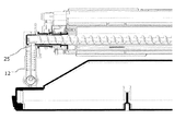
図11および図12に、ベルトユニット11から本体廃トナー搬送機構12へのベルト廃トナー受渡し口25のようす、とりわけベルトユニット11内に設けられたベルト廃トナー搬送スクリュー96の形状を示す。図11および図12は、鉛直方向でスクリューの軸を含む面に切った断面図であり、図11は、ベルトユニット11と本体廃トナー搬送機構とが接続された状態を示し、図12は、離された状態を示す。ベルトユニット11内において排出された廃トナーは、ベルト廃トナー搬送スクリュー96によってベルト廃トナー受渡し口25のベルト側開口部25aまで運ばれる。ベルトユニット廃トナー搬送スクリュー96は、軸の回りにスクリューフィンを備えたものであり、動力によりスクリューが回転することでスクリューフィンが廃トナーを掻き寄せて次々とベルト廃トナー受渡し口25のベルト側開口部25aまで運ぶ。ベルト廃トナー受渡し口25まで運ばれた廃トナーは、本体廃トナー搬送機構12により、最終的には廃トナーボトルユニットへと運ばれる。
FIGS. 11 and 12 show the shape of the belt waste
図11および図12に示すようにスクリューフィンがベルト廃トナー受渡し口25からトナーが落下していく向きに対向する上方の位置にも存在している。したがって、先行技術1と同様の問題がある。図示を省略するが、ドラム現像ユニットから本体廃トナー搬送機構への受渡し口、本体廃トナー搬送機構から廃トナーボトルユニットへの受渡し口もまた、同様にトナー受渡し口の真上にスクリューフィンが配置されている。したがって、これら3か所の受渡し口に同様の課題がある。
すなわち、電子写真方式記録装置における着脱可能な各消耗品ユニット(ドラム現像ユニット、ベルトユニット、廃トナーボトルユニット)と本体廃トナー搬送機構の受渡し口において、各ユニット着脱操作によるトナーこぼれ、その周辺の汚れが起き易いという問題があった。
As shown in FIGS. 11 and 12, the screw fin is also present at an upper position facing the direction in which the toner falls from the belt waste
That is, toner spillage due to each unit attaching / detaching operation at each delivery unit of the detachable consumable unit (drum developing unit, belt unit, waste toner bottle unit) and main body waste toner transport mechanism in the electrophotographic recording apparatus, There was a problem that dirt easily occurred.
本発明は、上記従来の課題を解決するものであって、トナー搬送の受渡し口で着脱する際にトナーこぼれを軽減する画像形成装置を提供することを目的とする。 SUMMARY An advantage of some aspects of the invention is that it provides an image forming apparatus that reduces toner spillage when the toner is attached and detached at a delivery port for toner conveyance.
上記課題を解決するために、本発明の画像形成装置は、トナーを搬送する第1のトナー搬送路と、該第1のトナー搬送路とは異なる方向へトナーを搬送する第2のトナー搬送路を有し、前記第1のトナー搬送路内に搬送方向へトナーを搬送するためのスクリューフィンが形成された搬送路に沿ったスクリューを有する第1のトナー搬送手段を備え、前記第1のトナー搬送路と前記第2のトナー搬送路は、前記第1のトナー搬送路から前記第2のトナー搬送路へトナーを送り込むために連通する為の口が設けられているそれぞれ第1の開口部と第2の開口部を有し、前記第1のトナー搬送路と前記第2のトナー搬送路は、前記第1の開口部と前記第2の開口部の部分で着脱可能に接続されており、前記第1のトナー搬送手段は、前記第1の開口部付近以外の少なくとも一部の前記スクリューには前記スクリューフィンが形成され、前記第1の開口部付近の少なくとも一部の前記スクリューには前記スクリューフィンが形成されないことを特徴とする。 In order to solve the above problems, an image forming apparatus according to the present invention includes a first toner conveyance path for conveying toner and a second toner conveyance path for conveying toner in a direction different from the first toner conveyance path. And a first toner transport unit having a screw along a transport path in which screw fins for transporting toner in the transport direction are formed in the first toner transport path. The conveyance path and the second toner conveyance path are respectively provided with a first opening provided with a port for communicating toner from the first toner conveyance path to the second toner conveyance path. A second opening, and the first toner transport path and the second toner transport path are detachably connected at the first opening and the second opening. The first toner conveying means has the first opening. At least a portion of the screw not nearly the screw fin is formed on the first at least a portion of the screw in the vicinity of the opening, characterized in that the screw fin is not formed.
本発明は、受渡し口の廃トナー落下方向に対向する上方以外の部分にスクリューフィンを備えたスクリューを有するトナー搬送手段を用いるので、受渡し口の廃トナー落下方向に対向する上方のスクリューに付着するトナーを軽減でき、トナー搬送の受渡し口で部材を着脱する際にトナーこぼれを軽減する画像形成装置を提供することができる。 In the present invention, since the toner conveying means having a screw provided with screw fins in a portion other than the upper portion facing the waste toner falling direction of the delivery port is used, it adheres to the upper screw facing the waste toner falling direction of the delivery port. It is possible to provide an image forming apparatus capable of reducing toner and reducing toner spillage when a member is attached and detached at a delivery port for toner conveyance.
以下、本発明の実施の形態について、図面を参照しながら詳細に説明する。
本発明は電子写真方式の画像形成装置における本体トナー搬送構成と当該画像形成装置に着脱可能な各消耗品ユニットが有するトナー搬送受渡し口の周辺部に関する。したがって、本発明に関係する部分について詳しく説明し、他の部分については簡単に説明する。
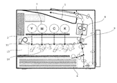
図1は、本発明に係る画像形成装置10の外観斜視図である。画像形成(印刷)前の用紙が給紙カセット4に収納され、画像形成(印刷)後の紙が排出トレー5に排出される。表示部6には、装置の状態、メニューなどが表示される。操作部7は、当該画像形成装置を操作者がメニュー操作をする際に用いるものであり、例えば上下左右の四つの押しボタンにより構成できる。操作者が操作して指示した内容に基づいて図示しないマイクロコンピュータを有する制御回路により制御されて各ユニットが連携して動作する。
なお、前扉3が設けられた側を前側と呼び、その反対側を奥側と呼ぶ。
Hereinafter, embodiments of the present invention will be described in detail with reference to the drawings.
The present invention relates to a main body toner conveyance structure in an electrophotographic image forming apparatus and a peripheral portion of a toner conveyance / delivery port of each consumable unit detachable from the image forming apparatus. Therefore, the parts related to the present invention will be described in detail, and the other parts will be described briefly.
FIG. 1 is an external perspective view of an
The side on which the
《画像形成について》
図2は、本発明に係る画像形成装置の機能を説明する概念図である。図1に示す前側から見た内部構造を示している。排紙トレー5の下方には、4色(イエロー、マゼンダ、シアン、ブラック)のトナーカートリッジ1が並列に設けられる。トナーカートリッジ1に収納されたトナーは、トナー縦搬送経路2を通って4つのドラム現像ユニット14にそれぞれ供給される。ドラム現像ユニット14は、最上部に感光体ドラム16を備える(図10参照)。そしてその近傍に帯電ローラ、光書き込みヘッド、現像ローラ等が配置される。トナーカートリッジからトナー縦搬送経路2を通ってドラム現像ユニットに供給されたトナーはドラム現像ユニット内でキャリアと混合されて感光体ドラム16に現像される。
<About image formation>
FIG. 2 is a conceptual diagram illustrating functions of the image forming apparatus according to the present invention. The internal structure seen from the front side shown in FIG. 1 is shown. Below the
ベルトユニット11に設けられた転写ベルト18は、ドラム現像ユニット14によって一次転写されたトナー像をさらに印刷用紙に二次転写すべく、トナー像を2次転写部9まで搬送する。そのトナー像が2次転写部9に近づくタイミングに合わせて給紙カセット4から印刷用紙が送られる。2次転写部9を通って画像が転写された紙は、定着ユニット8を通過して、排紙トレー5に排出される。両面印刷の場合は、排紙トレー5に現れた紙が再び装置内に戻されて、裏返された状態で2次転写部9、定着ユニット8を経て、再び排出トレー5に排出される。
以上、画像形成についてのトナーの働きに着目して画像形成装置のメインの機能である画像形成について説明した。廃トナーは各ドラム現像ユニット14において発生する。また、転写ベルト18からも発生する。廃トナーの処理については、図8を参照しつつ、後述する。
A
The image forming, which is the main function of the image forming apparatus, has been described above, focusing on the function of the toner for image forming. Waste toner is generated in each
《着脱可能なユニットの接続について》
図2に示すように、本画像形成装置にはトナーカットリッジ1が4つ並列に配置された下方に、ベルトユニット11が位置し、さらにその下方に、4つのドラム現像ユニット14が並列に配置され、その近くに廃トナーボトルユニット13が配置されている。ベルトユニット11、ドラム現像ユニット14、廃トナーボトルユニットは、いずれも着脱可能な消耗品ユニットとして構成されている。これらのユニットは画像形成する上でトナー供給や、廃トナーの排出などトナー搬送が不可欠な構成である。
<About connecting removable units>
As shown in FIG. 2, in this image forming apparatus, a
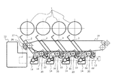
図3は、ベルトユニット、ドラム現像ユニット、本体廃トナー搬送機構、廃トナーボトルを接続した際の配置を示す斜視図である。図2が前扉を開けて見える様子を示したものであったのに対し、図3は、その反対側、すなわち奥側から見た様子を示す斜視図である。図3に示すように、ベルトユニット11の下方にドラム現像ユニット14が4つ並列に配置される。そして、本体廃トナー搬送機構12がベルトユニット11、ドラム現像ユニット14から排出された廃トナーを集めて、それらを廃トナーボトルユニット13へ貯蔵するために廃トナーを搬送すべく、ベルトユニット11、ドラム現像ユニット14、廃トナーボトル13と接続される。
FIG. 3 is a perspective view showing an arrangement when the belt unit, the drum developing unit, the main body waste toner transport mechanism, and the waste toner bottle are connected. FIG. 2 is a perspective view showing a state seen from the opposite side, that is, the back side, whereas FIG. 2 shows the state seen when the front door is opened. As shown in FIG. 3, four
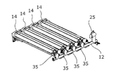
図4、図5、図6においては、4つの部材の接続を示すために、二つずつを描いて説明する。図4は、ベルトユニット11と、本体廃トナー搬送機構12とのベルト廃トナー受渡し口25における接続を示す斜視図である。図4に示されるように本体廃トナー搬送機構12は、ドラム現像ユニット14のためのドラム廃トナー受渡し口35を4つ有しており、さらにそれらよりも高い位置にベルトユニット11のためのベルト廃トナー受渡し口25を有している。転写ベルト18において発生した廃トナーは、ベルトユニット11に設けられたトナー搬送手段によりベルト廃トナー受渡し口25まで運ばれて、ベルト廃トナー受渡し口25から本体廃トナー搬送機構12へと送られる。ベルトユニット11に設けられたトナー搬送手段は、例えばスクリュー、回転軸の回りにフィンを備えたもの(後述するベルト廃トナー搬送スクリュー26)により構成することができる。ベルト廃トナー受渡し口25は、着脱可能になっており、接続されているときにはその部分からのトナー漏れがないように密着する。
In FIG. 4, FIG. 5, and FIG. 6, in order to show the connection of four members, two will be described. FIG. 4 is a perspective view showing a connection at the belt waste
図5は、ドラム現像ユニット14と、本体廃トナー搬送機構12とのドラム廃トナー受渡し口35における接続を示す斜視図である。4つのドラム現像ユニット14は、それぞれ本体トナー搬送構成12のドラム廃トナー受渡し口35に接続される。各ドラム現像ユニット14において、発生した廃トナーは、例えば現像ユニット内に設けられたスクリュー(後述するドラム廃トナー搬送スクリュー22)によりドラム廃トナー受渡し口35まで運ばれて、本体廃トナー搬送機構12へと送られる。
FIG. 5 is a perspective view showing a connection at the drum waste
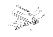
図6は、本体廃トナー搬送機構12と、廃トナーボトルユニット13とのボトル廃トナー受渡し口45における接続を示す斜視図である。本体廃トナー搬送機構12へと送られた廃トナーは本体廃トナー搬送機構12内に設けられるスクリューにより廃トナーボトル13へ搬送され、ボトル廃トナー受渡し口45から中に入り貯蔵される。
FIG. 6 is a perspective view showing the connection of the main body waste
《廃トナー処理について》
図7及び図8を参照しつつ、廃トナー処理について説明する。図7は、本発明に係る本体廃トナー搬送機構の他の部材との位置関係を説明する図である。図7は、前側から見た図である。図3〜6で説明したように、本体廃トナー搬送機構12は、奥側に設けられるので、煩雑を避けるために図7においては、二点鎖線でその輪郭を示している。4つのトナーカートリッジ1が並列に配置された位置の下方には、ベルトユニット11が位置する。ベルトユニット11は、転写ベルト18、ベルトクリーニングブレード27、ベルト廃トナー搬送スクリュー26を有するユニットであって、ドラム現像ユニット14が形成した画像(トナー像)を2次転写部9まで運ぶ機能を有する。図8においては、ベルトユニット11の枠などの機械的構造を描くと煩雑になるので、転写ベルト18、ベルトクリーニングブレード27、ベルト廃トナー搬送スクリュー26などの廃トナーの観点から主要な部分だけを描いている。
About waste toner processing
The waste toner processing will be described with reference to FIGS. FIG. 7 is a view for explaining the positional relationship with other members of the main body waste toner conveying mechanism according to the present invention. FIG. 7 is a view from the front side. As described with reference to FIGS. 3 to 6, the main body waste
ベルトクリーニングブレード27は、転写ベルト18上に残った未転写トナー及びレジスト調整用のパッチの現像層を掻き取る。ベルトクリーニングブレード27は、図7に示すように最上流側のドラム現像ユニット14よりもさらに上流位置において、転写ベルト18をクリーニングする。ベルト廃トナー搬送スクリュー26は、ベルトクリーニングブレード27によって掻き取られた廃トナーを、奥側方向に搬送するものであり、図示しない動力によりスクリューが回転し、軸の回りに設けられたスクリューフィンが廃トナーを運ぶように構成されている。ベルト廃トナー搬送スクリュー26は、ベルトクリーニングブレード26の近傍に設けられ、回転軸が前側から奥側に向かう向きに平行になるよう設けられる。また、ベルト廃トナー搬送スクリュー26は、ベルト廃トナー搬送路(不図示)の内部に設けられる。
ベルト廃トナー搬送路の排出口(後述する図10に示すベルト側開口部25a)は、ベルト廃トナー受渡し口25にて本体廃トナー搬送機構12に接続されて、転写ベルト18で発生した廃トナーは、本体廃トナー搬送機構12により搬送される。
The
A discharge port (
トナー縦搬送経路2は、トナーカートリッジ1から、ドラム現像ユニット14へ各色のトナーを供給するパイプ状の部材である。ドラム現像ユニット14は、その上部に感光ドラム16を露出させるものであって、感光ドラム16は転写ベルト18に接する。ドラム現像ユニット14は、廃トナー処理のために、ドラムクリーニングブレード20、ドラム廃トナー搬送スクリュー22を有している。ドラムクリーニングブレード20は、感光体ドラム16上に残った未転写トナーを掻き取り、感光体ドラム16の表面を清掃する。図8に示すようにドラムクリーニングブレード20は、それぞれ感光体ドラム16の右側に設けられる。ドラム廃トナー搬送スクリュー22は、図示しない動力によりスクリューが回転し、軸の回りに設けられたスクリューフィンが廃トナーを運ぶように構成される。ドラム廃トナー搬送スクリュー22は、ドラムクリーニングブレード20の近傍に設けられ、回転軸が前側から奥側に向かう向きに平行になるように設けられる。また、ドラム廃トナー搬送スクリュー22は、ドラム廃トナー搬送路(不図示)の内部に設けられる。
ドラム廃トナー搬送路の排出口は、ドラム廃トナー受渡し口35にて本体廃トナー搬送機構12に接続されて、感光ドラム16で発生した廃トナーは、本体廃トナー搬送機構12により搬送される。
The toner
The discharge port of the drum waste toner transport path is connected to the main body waste
《ボトル廃トナー受渡し口》
図8は、本体廃トナー搬送機構12の構造を、特に本体廃トナー搬送機構から廃トナーボトルへの受渡し口について示す図である。図7と同様に前側から見た図であるが、奥側にある本体廃トナー搬送機構12を描くために、転写ベルト18、ドラム現像ユニット14などを破線を用いて簡略化して描いてある。
図8に示すように、本体廃トナー搬送路43は、主に細長い円形断面のパイプ状に形成される。そして、画像形成装置10の奥側にほぼ水平に配置される。本体廃トナー搬送路43の内部には、廃トナーを搬送するための本体廃トナー搬送スクリュー42が設けられる。本体廃トナー搬送スクリュー42の長さは、本体廃トナー搬送路のほぼ全長にわたった長さである。本体廃トナー搬送スクリュー42は、本体廃トナー搬送路43の内部の左右端に設けられた軸受(不図示)に、回転自在に嵌合される。
《Bottle waste toner delivery port》
FIG. 8 is a diagram showing the structure of the main body waste
As shown in FIG. 8, the main body waste
本体廃トナー搬送路43の右端の外側には、本体廃トナー搬送スクリュー42を回転させるモータ44が取り付けられる。モータ44の回転軸に、本体廃トナー搬送スクリュー42の軸が、直接あるいは動力伝達部材を介して結合される。
A
本体廃トナー搬送路43には、ベルト廃トナー受渡し口26及び4つのドラム廃トナー受渡し口35が設けられ、ベルト廃トナー搬送スクリュー26、ドラム廃トナー搬送スクリュー22でそれぞれ搬送された廃トナーを受け入れる。図8における右側から左側へ廃トナーが搬送されて、最も左側(下流側)には、ボトル廃トナー受渡し口45が設けられ、廃トナーボトルユニット13と接続されて、搬送された廃トナーは、ボトル廃トナー受渡し口45において、重力に従って下方に落下し、廃トナーボトルユニット13に蓄積される。
The main body waste
ここで、本発明の最も特徴的部分は、本体廃トナー搬送スクリュー42の周囲に螺旋状に設けるスクリューフィンをどこに設けて、どこには設けないかという点である。図8に描かれた本体廃トナー搬送スクリュー42の形状からわかるように、スクリューフィンは、本体廃トナー搬送スクリュー42の全長にわたってほとんどの箇所に設けられている。しかし、ボトル廃トナー受渡し口45においては、廃トナーが落下する方向に対抗する上方にあたる本体廃トナー搬送スクリュー42の部分には、スクリューフィンを設けず、回転軸のみとなっている。
これにより、スクリューフィンを設けないこととした当該部分には、廃トナーの付着が少なくなるので、本体廃トナー搬送機構と、廃トナーボトルユニットとを着脱する際の振動などによる廃トナーの飛散が軽減できる。
Here, the most characteristic part of the present invention is where the screw fins provided spirally around the main body waste
As a result, the waste toner adheres to the portions where the screw fins are not provided, so that the waste toner is scattered due to vibration when the main body waste toner transport mechanism and the waste toner bottle unit are attached and detached. Can be reduced.
《ベルト廃トナー受渡し口について》
ベルト廃トナー受渡し口25近傍におけるスクリューフィンを示すべく、ベルトユニットから本体廃トナー搬送機構への受渡し口を含めてベルト廃トナー搬送路の内部構造、スクリューフィンの形状などを図9に示す。図9に示すように、転写ベルト18の幅いっぱいに発生し得る廃トナーをベルトクリーニングブレード27で掻き取ってベルト廃トナー搬送路に受け入れてベルト廃トナー受渡し口25の方へ搬送すべくベルト廃トナー搬送スクリュー26が設けられている。ベルト廃トナー搬送スクリュー26は、図示しない動力により回転し、当該スクリューの周囲に設けられたスクリューフィンにより廃トナーは搬送される。四角で囲った部分に着目すると、ベルト廃トナー受渡し口25にてベルト廃トナー搬送路は本体廃トナー搬送機構12と接続している。この接続箇所において、当該箇所の廃トナーが落下する方向と対抗する上方の部分では、スクリューにスクリューフィンが設けられていない。このことにより、ベルトユニット11と本体廃トナー搬送機構12との着脱の際に廃トナーが飛び散ることを防止できる。この接続部分においてはトナーがこぼれないような密着した接続がなされている。
<Belt waste toner delivery port>
In order to show the screw fins in the vicinity of the belt waste
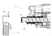
図10は、図9の四角で囲った部分、すなわちベルト廃トナー受渡し口付近の拡大図であり、ベルトユニットと、本体廃トナー搬送機構とを離した状態を示している。ベルト廃トナー受渡し口25において、ベルトユニット11側の開口部(第1の開口部)をベルト側開口部25aと呼び、本体廃トナー搬送機構12側の開口部(第2の開口部)を本体側開口部25bと呼ぶこととする。
本体側開口部25bの付近のベルト廃トナー搬送スクリュー26には、廃トナーが落下する方向に対向する上方において、スクリューフィンが設けられていないことが描かれている。
FIG. 10 is an enlarged view of the portion surrounded by the square in FIG. 9, that is, the vicinity of the belt waste toner delivery port, and shows a state in which the belt unit and the main body waste toner transport mechanism are separated. In the belt waste
The belt waste
《ドラム廃トナー受渡し口について》
ドラム廃トナー受渡し口35についても、ベルト廃トナー受渡し口25と同様に本発明を適用できる。すなわち、ドラム現像ユニット側の開口部(第1の開口部)と本体廃トナー搬送機構側の開口部(第2の開口部)においても、第1の開口部付近のスクリューにはスクリューフィンを形成しないこととする。これにより、部品交換、メンテナンスのときなどのトナーの飛散を防止できる。
より上位概念で言えば、廃トナーに限らず、トナーを一方の部材から他の部材へとスクリューフィンで搬送する際に、その接続部分である受渡し口においては、トナーが落下する方向に対向する上方にあたる部分のスクリューには、スクリューフィンを設けないこととすることが好ましい。これにより着脱操作の際のトナーの飛散を防止できる。
<Drum waste toner delivery port>
The present invention can be applied to the drum waste
In terms of a higher level concept, not only waste toner but also toner is transported from one member to another member with screw fins, the delivery port, which is the connecting portion, faces the direction in which the toner falls. It is preferable that screw fins are not provided in the upper portion of the screw. As a result, it is possible to prevent toner from being scattered during the attaching / detaching operation.
本発明において、廃トナー搬送装置というときに、本体廃トナー搬送機構12がそれに該当する。それのみならず、ベルト廃トナー搬送路、ベルト廃トナー搬送スクリュー26、を含む装置もまた、廃トナー搬送装置に該当する。
さらにドラム廃トナー搬送路、ドラム廃トナー搬送スクリュー22を含む装置もまた、廃トナー搬送装置に該当する。
そして、本発明は、ボトル廃トナー受渡し口45、ベルト廃トナー受渡し口25、ドラム廃トナー受渡し口35に共通に適用できる。単に「受渡し口」というときには、これら3種類の受渡し口を総括する上位概念で用いている。
In the present invention, the waste
Further, the apparatus including the drum waste toner transport path and the drum waste
The present invention can be commonly applied to the bottle waste
本発明のいくつかの実施形態を説明したが、本発明は特許請求の範囲に記載された発明とその均等の範囲に含まれる。以下に、本願出願の当初の特許請求の範囲に記載された発明を付記する。
[付記1]
Although several embodiments of the present invention have been described, the present invention is included in the invention described in the claims and the equivalents thereof. Hereinafter, the invention described in the scope of claims of the present application will be appended.
[Appendix 1]
トナーを搬送する第1のトナー搬送路と、該第1のトナー搬送路とは異なる方向へトナーを搬送する第2のトナー搬送路を有し、
前記第1のトナー搬送路内に搬送方向へトナーを搬送するためのスクリューフィンが形成された搬送路に沿ったスクリューを有する第1のトナー搬送手段を備え、
前記第1のトナー搬送路と前記第2のトナー搬送路は、前記第1のトナー搬送路から前記第2のトナー搬送路へトナーを送り込むために連通する為の口が設けられているそれぞれ第1の開口部と第2の開口部を有し、
前記第1のトナー搬送路と前記第2のトナー搬送路は、前記第1の開口部と前記第2の開口部の部分で着脱可能に接続されており、
前記第1のトナー搬送手段は、前記第1の開口部付近以外の少なくとも一部の前記スクリューには前記スクリューフィンが形成され、前記第1の開口部付近の少なくとも一部の前記スクリューには前記スクリューフィンが形成されないことを特徴とするトナー搬送装置。
[付記2]
A first toner transport path for transporting toner and a second toner transport path for transporting toner in a direction different from the first toner transport path;
A first toner conveying means having a screw along a conveying path formed with screw fins for conveying toner in the conveying direction in the first toner conveying path;
The first toner conveyance path and the second toner conveyance path are each provided with a port for communicating with the first toner conveyance path so as to send toner to the second toner conveyance path. Having one opening and a second opening;
The first toner conveyance path and the second toner conveyance path are detachably connected at the first opening and the second opening.
In the first toner conveying means, the screw fin is formed on at least a part of the screw other than the vicinity of the first opening, and the screw fin is formed on at least a part of the screw near the first opening. A toner conveying device, wherein no screw fin is formed.
[Appendix 2]
前記第1の開口部と前記第2の開口部での着脱可能な接続は、トナーこぼれを防止すべく、密着した接続であることを特徴とする付記1に記載のトナー搬送装置。
[付記3]
The toner conveying apparatus according to
[Appendix 3]
前記第1のトナー搬送路内の前記スクリューには、螺旋状のスクリューフィンが形成されていることを特徴とする付記1または2に記載のトナー搬送装置。
[付記4]
3. The toner conveying apparatus according to
[Appendix 4]
廃トナーを貯蔵する廃トナーボトルユニットまで該廃トナーを搬送する搬送路となる本体廃トナー搬送路を有し、
前記本体廃トナー搬送路内に搬送方向へ廃トナーを搬送するためのスクリューフィンが形成された搬送路に沿ったスクリューを有する本体廃トナー搬送手段を備え、
前記本体廃トナー搬送路は、前記廃トナーを貯蔵する前記廃トナーボトルユニットへ前記廃トナーを受け渡すボトル受渡し口が設けられているボトル受渡し部と、感光体ドラムにて発生した廃トナーを受け入れるドラム廃トナー受渡し口が設けられているドラム廃トナー受渡し部と、転写ベルトにて発生した廃トナーを受け入れるベルト廃トナー受渡し口が設けられているベルト廃トナー受渡し部と、を有し、
前記ボトル受渡し部と前記廃トナーボトルユニットとの接続、前記ドラム廃トナー受渡し部と前記感光体ドラムにて発生した廃トナーを受け入れる際の接続、前記ベルト廃トナー受渡し部と前記転写ベルトにて発生した廃トナーを受け入れる際の接続は、いずれも着脱可能に接続され、
前記ボトル受渡し部及び前記ドラム廃トナー受渡し部及び前記ベルト廃トナー受渡し部付近以外の少なくとも一部の前記スクリューには前記スクリューフィンが形成され、前記ボトル受渡し部及び前記ドラム廃トナー受渡し部及び前記ベルト廃トナー受渡し部付近の少なくとも一部の前記スクリューには前記スクリューフィンが形成されないことを特徴とするトナー搬送装置。
[付記5]
A main body waste toner transport path serving as a transport path for transporting the waste toner to a waste toner bottle unit for storing waste toner;
A main body waste toner transport means having a screw along a transport path formed with screw fins for transporting the waste toner in the transport direction in the main body waste toner transport path;
The main body waste toner conveyance path receives a bottle delivery unit provided with a bottle delivery port for delivering the waste toner to the waste toner bottle unit for storing the waste toner, and waste toner generated on the photosensitive drum. A drum waste toner delivery unit provided with a drum waste toner delivery port, and a belt waste toner delivery unit provided with a belt waste toner delivery port for receiving waste toner generated on the transfer belt,
Connection between the bottle delivery unit and the waste toner bottle unit, connection for receiving waste toner generated in the drum waste toner delivery unit and the photosensitive drum, generated in the belt waste toner delivery unit and the transfer belt All of the connections for accepting the waste toner are detachable,
The screw fins are formed on at least some of the screws except for the vicinity of the bottle delivery unit, the drum waste toner delivery unit, and the belt waste toner delivery unit, and the bottle delivery unit, the drum waste toner delivery unit, and the belt. The toner conveying device, wherein the screw fin is not formed on at least a part of the screw in the vicinity of the waste toner delivery unit.
[Appendix 5]
前記ボトル受渡し部と前記廃トナーボトルユニットとの接続、前記ドラム廃トナー受渡し部と前記感光体ドラムにて発生した廃トナーを受け入れる際の接続、前記ベルト廃トナー受渡し部と前記転写ベルトにて発生した廃トナーを受け入れる際の接続は、いずれも廃トナーこぼれを防止すべく、密着した接続であることを特徴とする付記3に記載のトナー搬送装置。
[付記6]
Connection between the bottle delivery unit and the waste toner bottle unit, connection for receiving waste toner generated in the drum waste toner delivery unit and the photosensitive drum, generated in the belt waste toner delivery unit and the
[Appendix 6]
前記本体廃トナー搬送路内の前記スクリューには、螺旋状のスクリューフィンが形成されていることを特徴とする付記4または5に記載のトナー搬送装置。
[付記7]
6. The toner conveying apparatus according to
[Appendix 7]
付記1乃至6のいずれか1項に記載のトナー搬送装置を有することを特徴とする画像形成装置。
An image forming apparatus comprising the toner conveying device according to any one of
本発明は、電子写真方式の画像形成装置に利用することができる。また、電子写真方式の画像形成装置用の廃トナー搬送装置に利用することができる。 The present invention can be used in an electrophotographic image forming apparatus. Further, the present invention can be used for a waste toner conveying device for an electrophotographic image forming apparatus.
1 トナーカートリッジ
2 トナー縦搬送経路
3 前扉
4 給紙カセット
5 排紙トレー
6 表示部
7 操作部
8 定着装置
9 2次転写部
10 画像形成装置
11 ベルトユニット
12 本体廃トナー搬送機構
13 廃トナーボトルユニット
14 ドラム現像ユニット
16 感光体ドラム
18 転写ベルト
20 ドラムクリーニングブレード
22 ドラム廃トナー搬送スクリュー
25 ベルト廃トナー受渡し口
25a ベルト側開口部(第1の開口部)
25b 本体側開口部(第2の開口部)
26、96 ベルト廃トナー搬送スクリュー
27 ベルトクリーニングブレード
35 ドラム廃トナー受渡し口
42 本体廃トナー搬送スクリュー
43 本体廃トナー搬送路
44 モータ
45 ボトル廃トナー受渡し口
DESCRIPTION OF
25b Main body side opening (second opening)
26, 96 Belt waste
Claims (7)
前記第1のトナー搬送路内に搬送方向へトナーを搬送するためのスクリューフィンが形成された搬送路に沿ったスクリューを有する第1のトナー搬送手段を備え、
前記第1のトナー搬送路と前記第2のトナー搬送路は、前記第1のトナー搬送路から前記第2のトナー搬送路へトナーを送り込むために連通する為の口が設けられているそれぞれ第1の開口部と第2の開口部を有し、
前記第1のトナー搬送路と前記第2のトナー搬送路は、前記第1の開口部と前記第2の開口部の部分で着脱可能に接続されており、
前記第1のトナー搬送手段は、前記第1の開口部付近以外の少なくとも一部の前記スクリューには前記スクリューフィンが形成され、前記第1の開口部付近の少なくとも一部の前記スクリューには前記スクリューフィンが形成されないことを特徴とするトナー搬送装置。 A first toner transport path for transporting toner and a second toner transport path for transporting toner in a direction different from the first toner transport path;
A first toner conveying means having a screw along a conveying path formed with screw fins for conveying toner in the conveying direction in the first toner conveying path;
The first toner conveyance path and the second toner conveyance path are each provided with a port for communicating with the first toner conveyance path so as to send toner to the second toner conveyance path. Having one opening and a second opening;
The first toner conveyance path and the second toner conveyance path are detachably connected at the first opening and the second opening.
In the first toner conveying means, the screw fin is formed on at least a part of the screw other than the vicinity of the first opening, and the screw fin is formed on at least a part of the screw near the first opening. A toner conveying device, wherein no screw fin is formed.
前記本体廃トナー搬送路内に搬送方向へ廃トナーを搬送するためのスクリューフィンが形成された搬送路に沿ったスクリューを有する本体廃トナー搬送手段を備え、
前記本体廃トナー搬送路は、前記廃トナーを貯蔵する前記廃トナーボトルユニットへ前記廃トナーを受け渡すボトル受渡し口が設けられているボトル受渡し部と、感光体ドラムにて発生した廃トナーを受け入れるドラム廃トナー受渡し口が設けられているドラム廃トナー受渡し部と、転写ベルトにて発生した廃トナーを受け入れるベルト廃トナー受渡し口が設けられているベルト廃トナー受渡し部と、を有し、
前記ボトル受渡し部と前記廃トナーボトルユニットとの接続、前記ドラム廃トナー受渡し部と前記感光体ドラムにて発生した廃トナーを受け入れる際の接続、前記ベルト廃トナー受渡し部と前記転写ベルトにて発生した廃トナーを受け入れる際の接続は、いずれも着脱可能に接続され、
前記ボトル受渡し部及び前記ドラム廃トナー受渡し部及び前記ベルト廃トナー受渡し部付近以外の少なくとも一部の前記スクリューには前記スクリューフィンが形成され、前記ボトル受渡し部及び前記ドラム廃トナー受渡し部及び前記ベルト廃トナー受渡し部付近の少なくとも一部の前記スクリューには前記スクリューフィンが形成されないことを特徴とするトナー搬送装置。 A main body waste toner transport path serving as a transport path for transporting the waste toner to a waste toner bottle unit for storing waste toner;
A main body waste toner transport means having a screw along a transport path formed with screw fins for transporting the waste toner in the transport direction in the main body waste toner transport path;
The main body waste toner conveyance path receives a bottle delivery unit provided with a bottle delivery port for delivering the waste toner to the waste toner bottle unit for storing the waste toner, and waste toner generated on the photosensitive drum. A drum waste toner delivery unit provided with a drum waste toner delivery port, and a belt waste toner delivery unit provided with a belt waste toner delivery port for receiving waste toner generated on the transfer belt,
Connection between the bottle delivery unit and the waste toner bottle unit, connection for receiving waste toner generated in the drum waste toner delivery unit and the photosensitive drum, generated in the belt waste toner delivery unit and the transfer belt All of the connections for accepting the waste toner are detachable,
The screw fins are formed on at least some of the screws except for the vicinity of the bottle delivery unit, the drum waste toner delivery unit, and the belt waste toner delivery unit, and the bottle delivery unit, the drum waste toner delivery unit, and the belt. The toner conveying device, wherein the screw fin is not formed on at least a part of the screw in the vicinity of the waste toner delivery unit.
An image forming apparatus comprising the toner conveying device according to claim 1.
Priority Applications (1)
| Application Number | Priority Date | Filing Date | Title |
|---|---|---|---|
| JP2013195406A JP2015060169A (en) | 2013-09-20 | 2013-09-20 | Image formation device and waste toner transportation device |
Applications Claiming Priority (1)
| Application Number | Priority Date | Filing Date | Title |
|---|---|---|---|
| JP2013195406A JP2015060169A (en) | 2013-09-20 | 2013-09-20 | Image formation device and waste toner transportation device |
Publications (2)
| Publication Number | Publication Date |
|---|---|
| JP2015060169A true JP2015060169A (en) | 2015-03-30 |
| JP2015060169A5 JP2015060169A5 (en) | 2016-10-06 |
Family
ID=52817717
Family Applications (1)
| Application Number | Title | Priority Date | Filing Date |
|---|---|---|---|
| JP2013195406A Pending JP2015060169A (en) | 2013-09-20 | 2013-09-20 | Image formation device and waste toner transportation device |
Country Status (1)
| Country | Link |
|---|---|
| JP (1) | JP2015060169A (en) |
Cited By (1)
| Publication number | Priority date | Publication date | Assignee | Title |
|---|---|---|---|---|
| US11809097B2 (en) | 2021-03-19 | 2023-11-07 | Ricoh Company, Ltd. | Powder conveying device and image forming apparatus incorporating the powder conveying device |
Citations (6)
| Publication number | Priority date | Publication date | Assignee | Title |
|---|---|---|---|---|
| JPH0822179A (en) * | 1994-07-08 | 1996-01-23 | Canon Inc | Developer replenishment device |
| JP2000137374A (en) * | 1998-10-29 | 2000-05-16 | Canon Inc | Developer supplying device, developing device, and image forming device provided with them |
| JP2000214667A (en) * | 1999-01-20 | 2000-08-04 | Toshiba Corp | Developer supply device |
| JP2008040223A (en) * | 2006-08-08 | 2008-02-21 | Fuji Xerox Co Ltd | Waste toner conveying mechanism |
| JP2009015110A (en) * | 2007-07-06 | 2009-01-22 | Kyocera Mita Corp | Toner recovery device and image forming apparatus |
| JP2010224004A (en) * | 2009-03-19 | 2010-10-07 | Fuji Xerox Co Ltd | Image forming apparatus |
-
2013
- 2013-09-20 JP JP2013195406A patent/JP2015060169A/en active Pending
Patent Citations (6)
| Publication number | Priority date | Publication date | Assignee | Title |
|---|---|---|---|---|
| JPH0822179A (en) * | 1994-07-08 | 1996-01-23 | Canon Inc | Developer replenishment device |
| JP2000137374A (en) * | 1998-10-29 | 2000-05-16 | Canon Inc | Developer supplying device, developing device, and image forming device provided with them |
| JP2000214667A (en) * | 1999-01-20 | 2000-08-04 | Toshiba Corp | Developer supply device |
| JP2008040223A (en) * | 2006-08-08 | 2008-02-21 | Fuji Xerox Co Ltd | Waste toner conveying mechanism |
| JP2009015110A (en) * | 2007-07-06 | 2009-01-22 | Kyocera Mita Corp | Toner recovery device and image forming apparatus |
| JP2010224004A (en) * | 2009-03-19 | 2010-10-07 | Fuji Xerox Co Ltd | Image forming apparatus |
Cited By (1)
| Publication number | Priority date | Publication date | Assignee | Title |
|---|---|---|---|---|
| US11809097B2 (en) | 2021-03-19 | 2023-11-07 | Ricoh Company, Ltd. | Powder conveying device and image forming apparatus incorporating the powder conveying device |
Similar Documents
| Publication | Publication Date | Title |
|---|---|---|
| JP4689327B2 (en) | Image forming apparatus | |
| JP4608535B2 (en) | Developer collection container, developer cartridge, development unit, and image forming apparatus | |
| JP2007298543A (en) | Toner cartridge | |
| JP2006195401A (en) | Electrophotographic image forming device and process cartridge | |
| JP2008175956A (en) | Powder conveying device, toner conveying device, process cartridge and image forming apparatus | |
| JP6124632B2 (en) | Collected developer container and image forming apparatus | |
| JP2008129210A (en) | Developing device | |
| JP2016031436A (en) | Image forming apparatus | |
| JP5532947B2 (en) | Image forming unit and image forming apparatus | |
| JP2003241512A (en) | Image forming apparatus | |
| JP2010054570A (en) | Visible image forming apparatus and image forming apparatus | |
| JP3705364B2 (en) | Image forming apparatus, process cartridge and developing device used therefor | |
| CN107229209B (en) | Waste toner recovery device and image forming apparatus having the same | |
| JP2015060169A (en) | Image formation device and waste toner transportation device | |
| JP5907613B2 (en) | Collected toner container and image forming apparatus | |
| JP6489076B2 (en) | Image forming apparatus | |
| JP4615457B2 (en) | Image forming apparatus | |
| JP2007298712A (en) | Toner cartridge | |
| JP2014145833A (en) | Developer storage body, developing and image forming unit, and image forming apparatus | |
| JP2018017966A (en) | Image forming device, and toner container mounted on image forming device | |
| JP2011221351A (en) | Developing device and image forming device | |
| JP2017044869A (en) | Waste toner storage container and image forming apparatus | |
| JP2015203706A (en) | Developing unit, image forming unit, and image forming apparatus | |
| JP6233291B2 (en) | Image forming apparatus | |
| JP2008122662A (en) | Developing device |
Legal Events
| Date | Code | Title | Description |
|---|---|---|---|
| A521 | Written amendment |
Free format text: JAPANESE INTERMEDIATE CODE: A523 Effective date: 20160808 |
|
| A621 | Written request for application examination |
Free format text: JAPANESE INTERMEDIATE CODE: A621 Effective date: 20160808 |
|
| A977 | Report on retrieval |
Free format text: JAPANESE INTERMEDIATE CODE: A971007 Effective date: 20170427 |
|
| A131 | Notification of reasons for refusal |
Free format text: JAPANESE INTERMEDIATE CODE: A131 Effective date: 20170530 |
|
| A02 | Decision of refusal |
Free format text: JAPANESE INTERMEDIATE CODE: A02 Effective date: 20171212 |