JP2015057791A - Lighting device - Google Patents
Lighting device Download PDFInfo
- Publication number
- JP2015057791A JP2015057791A JP2014235171A JP2014235171A JP2015057791A JP 2015057791 A JP2015057791 A JP 2015057791A JP 2014235171 A JP2014235171 A JP 2014235171A JP 2014235171 A JP2014235171 A JP 2014235171A JP 2015057791 A JP2015057791 A JP 2015057791A
- Authority
- JP
- Japan
- Prior art keywords
- light
- cover
- center
- lighting device
- led module
- Prior art date
- Legal status (The legal status is an assumption and is not a legal conclusion. Google has not performed a legal analysis and makes no representation as to the accuracy of the status listed.)
- Granted
Links
- 238000005286 illumination Methods 0.000 claims abstract description 20
- 238000005192 partition Methods 0.000 claims description 3
- 230000002093 peripheral effect Effects 0.000 description 17
- 230000005855 radiation Effects 0.000 description 8
- 238000010586 diagram Methods 0.000 description 6
- 239000000758 substrate Substances 0.000 description 4
- NIXOWILDQLNWCW-UHFFFAOYSA-N acrylic acid group Chemical group C(C=C)(=O)O NIXOWILDQLNWCW-UHFFFAOYSA-N 0.000 description 3
- 239000000463 material Substances 0.000 description 3
- 229910052751 metal Inorganic materials 0.000 description 3
- 239000002184 metal Substances 0.000 description 3
- 229920003002 synthetic resin Polymers 0.000 description 3
- 239000000057 synthetic resin Substances 0.000 description 3
- XEEYBQQBJWHFJM-UHFFFAOYSA-N Iron Chemical compound [Fe] XEEYBQQBJWHFJM-UHFFFAOYSA-N 0.000 description 2
- 229910052782 aluminium Inorganic materials 0.000 description 2
- XAGFODPZIPBFFR-UHFFFAOYSA-N aluminium Chemical compound [Al] XAGFODPZIPBFFR-UHFFFAOYSA-N 0.000 description 2
- 239000011248 coating agent Substances 0.000 description 2
- 238000000576 coating method Methods 0.000 description 2
- 238000005401 electroluminescence Methods 0.000 description 2
- 238000007789 sealing Methods 0.000 description 2
- 241000238631 Hexapoda Species 0.000 description 1
- 239000000853 adhesive Substances 0.000 description 1
- 230000001070 adhesive effect Effects 0.000 description 1
- 239000004020 conductor Substances 0.000 description 1
- 238000009792 diffusion process Methods 0.000 description 1
- 230000000694 effects Effects 0.000 description 1
- 239000013013 elastic material Substances 0.000 description 1
- 230000004313 glare Effects 0.000 description 1
- 229910052742 iron Inorganic materials 0.000 description 1
- 230000003287 optical effect Effects 0.000 description 1
- 239000003973 paint Substances 0.000 description 1
- 229920000515 polycarbonate Polymers 0.000 description 1
- 239000004417 polycarbonate Substances 0.000 description 1
- -1 polyethylene terephthalate Polymers 0.000 description 1
- 229920000139 polyethylene terephthalate Polymers 0.000 description 1
- 239000005020 polyethylene terephthalate Substances 0.000 description 1
- 230000002265 prevention Effects 0.000 description 1
- 238000004381 surface treatment Methods 0.000 description 1
- 238000002834 transmittance Methods 0.000 description 1
Images


Abstract
Description
本発明は、光源からの光を透過する透光部を備えた照明装置に関する。 The present invention relates to an illuminating device including a translucent part that transmits light from a light source.
住宅の室内用の照明装置としては、従来、白熱電球、蛍光灯などの光源を備えるものが用いられている。一方で、近年、発光ダイオード(LED)の高輝度化に伴い、白熱電球や蛍光灯などの光源に代えて、低消費電力、長寿命等の特性を有するLEDが照明装置の光源として用いられるようになりつつある。 2. Description of the Related Art Conventionally, an illumination device for indoor use has a light source such as an incandescent bulb and a fluorescent lamp. On the other hand, in recent years, with the increase in the brightness of light emitting diodes (LEDs), instead of light sources such as incandescent bulbs and fluorescent lamps, LEDs having characteristics such as low power consumption and long life have been used as light sources for lighting devices. It is becoming.
特許文献1には、光源であるLEDと該LEDに電力を供給する電源回路などを筐体底面に並設した照明装置が開示されている。
しかし、特許文献1の照明装置は、筐体の底面は3つの部分に区画し、LEDを配した2つの発光部に光を拡散させる拡散板を設け、2つの発光部の間にLEDに電力を供給する電源回路等を収容する収容部を設けてある。このため、照明装置を点灯させた際、拡散板からは光が放射されて発光するものの、拡散板の間に挟まれた部分には発光しない非発光部が存在するので、点灯状態に違和感を覚えるユーザがあった。
However, in the lighting device of
本発明は斯かる事情に鑑みてなされたものであり、点灯状態における非発光部を低減することができる照明装置を提供することを目的とする。 This invention is made | formed in view of such a situation, and it aims at providing the illuminating device which can reduce the non-light-emitting part in a lighting state.
本発明に係る照明装置は、電源回路部品と光源とを区画して収容する照明装置本体と、前記電源回路部品に対応する位置に開口部を有し、前記光源からの光を透過して発光する透光部と、該透光部と並設するように前記開口部を覆い、前記透光部から出射された光を導いて発光する導光部材とを備えることを特徴とする。 An illumination device according to the present invention has an illumination device body that partitions and accommodates a power circuit component and a light source, and has an opening at a position corresponding to the power circuit component, and transmits light from the light source to emit light. And a light guide member that covers the opening so as to be juxtaposed with the light-transmitting portion and guides light emitted from the light-transmitting portion to emit light.
本発明にあっては、電源回路等の内蔵部品と光源とを区画して収容する照明装置本体と、光源からの光を透過して発光する透光部と、内蔵部品の前面に位置して透光部と並設され、光源からの光を導いて発光する導光部材とを備える。これにより、導光部材から光を放射させることができるので、照明装置の点灯状態における非発光部を低減することができる。 In the present invention, the lighting device main body that partitions and accommodates the built-in components such as the power supply circuit and the light source, the translucent portion that transmits light from the light source and emits light, and the front of the built-in components And a light guide member that is arranged in parallel with the light transmitting part and guides light from the light source to emit light. Thereby, since light can be radiated | emitted from a light guide member, the non-light-emitting part in the lighting state of an illuminating device can be reduced.
本発明に係る照明装置は、前記導光部材は、前記透光部と略同一面をなすように並設されていることを特徴とする。 The illuminating device according to the present invention is characterized in that the light guide member is arranged in parallel so as to be substantially flush with the translucent part.
本発明に係る照明装置は、前記導光部材は、前記開口部の一部を覆うように設けられていることを特徴とする。 The illumination device according to the present invention is characterized in that the light guide member is provided so as to cover a part of the opening.
本発明に係る照明装置は、前記導光部材は、合成樹脂からなることを特徴とする。 In the illumination device according to the present invention, the light guide member is made of a synthetic resin.
本発明に係る照明装置は、光が入射する前記導光部材の端部を前記透光部に密着させてあることを特徴とする。 The illuminating device according to the present invention is characterized in that an end portion of the light guide member into which light is incident is in close contact with the light transmitting portion.
本発明にあっては、導光部材の端部を透光部に密着させてある。これにより、導光部材と透光部との間に発光しない箇所が生じることを防止することができ、点灯状態の違和感を一層解消することができる。 In this invention, the edge part of the light guide member is stuck to the translucent part. Thereby, it can prevent that the location which does not light-emit between the light guide member and the translucent part arises, and the discomfort of a lighting state can be further eliminated.
本発明に係る照明装置は、前記透光部に密着する前記端部を鏡面加工してあることを特徴とする。 The illumination device according to the present invention is characterized in that the end portion in close contact with the light transmitting portion is mirror-finished.
本発明にあっては、導光部材の透光部に密着する端部を鏡面加工してある。これにより、導光部材(第2の反射部)内部に取り込む光の量を増加させることができ、導光部材からの発光量を増加させることができる。 In the present invention, the end portion that is in close contact with the light transmitting portion of the light guide member is mirror-finished. Thereby, the quantity of the light taken in inside a light guide member (2nd reflection part) can be increased, and the emitted light amount from a light guide member can be increased.
本発明によれば、照明装置の点灯状態における非発光部を低減することができる。 ADVANTAGE OF THE INVENTION According to this invention, the non-light-emitting part in the lighting state of an illuminating device can be reduced.
(実施の形態1)
以下、本発明をその実施の形態を示す図面に基づいて説明する。図1は実施の形態1の照明装置100の構成の一例を示す外観図であり、図2は実施の形態1の照明装置100の構成の一例を示す分解斜視図である。以下の説明では、照明装置100として、天井等の取付面に着脱可能に取り付けることができるシーリングライトを例として挙げるが、本実施の形態の照明装置100は、シーリングライトに限定されるものではない。
(Embodiment 1)
Hereinafter, the present invention will be described with reference to the drawings illustrating embodiments thereof. FIG. 1 is an external view showing an example of the configuration of the
図1、図2に示すように、照明装置100は、金属製(例えば、アルミニウム製)であって円板状の照明装置本体としてのシャーシ1を天井等に取り付け、シャーシ1には、円板状であって光拡散性を有する透光部としての透光カバー7を取り付けてある。透光カバー7の中央部には円板状の開口部71、後述のセンタ板8を取り付けるための取付部72を設けてある。センタ板8には、導光部材としてのセンタカバー9を着脱可能に取り付けることができる。
As shown in FIGS. 1 and 2, a
照明装置100は、シャーシ1、透光カバー7、センタカバー9の他に、光源としての8個のLEDモジュール2、断面形状が略U字状であって、例えば、アルミニウムなどの熱伝導性に優れた金属製の8個の放熱フィン3、LEDモジュール2で発する光を所要の方向へ進行させるための8個のレンズ4、LEDモジュール2に所要の電流を供給する電源部(電源回路)及びLEDモジュール2の明るさを制御する制御部(制御回路)などを実装し、中央に開口を形成した外周が八角形状の回路基板5、シャーシ1と回路基板5とを電気的に絶縁するための絶縁シート51、後述の取付アダプタ63に嵌合する嵌合部としての第1リング材6及び第2リング材60、密閉性を保つための環状の弾性材10、第1リング材6に固定されるコネクタを有し、商用電源を回路基板5へ供給するためのハーネス61、並びに回路基板5等の内蔵部品を覆う覆板としてのセンタ板8などを備える。
The
第1リング材6と第2リング材60とは、回路基板5を間に挟んだ状態にして嵌合するようにしてある。回路基板5の八角形状の外周の各辺には、放熱フィン3、LEDモジュール2、レンズ4がビス等で取り付けられる。また、放熱フィン3は、センタ板8にビス等で固定されるとともに、シャーシ1にもビス等で固定される。
The
図3は実施の形態1の照明装置100の構成の要部一例を示す断面図である。図3に示すように、扁平な略円柱形状の取付アダプタ63は、商用電源からの電源線が接続されたコネクタ(不図示)を有し、天井に設けられた引掛けシーリング(引掛部)62に引掛けられる(係合する)。これにより、取付アダプタ63は、電気的及び機械的に引掛けシーリング62に接続される。取付アダプタ63のコネクタ(不図示)を、ハーネス61のコネクタに接続することにより、回路基板5に商用電源のAC電圧が供給される。また、シャーシ1に固定された第1リング材6及び第2リング材60のいずれかと取付アダプタ63とを嵌合させることにより、照明装置100を天井に設置することができる。
FIG. 3 is a cross-sectional view showing an example of a main part of the configuration of
回路基板5には、照度センサを実装したセンサ基板(いずれも不図示)が接続されている。照度センサは、例えば、フォトトランジスタ、あるいはフォトダイオードを備え、検出した照度に応じた電気信号を出力する。照度センサで検出した照度に応じて、制御部(不図示)は、LEDモジュール2からの光の明るさを調整する。例えば、制御部は、照度センサで検出する照度が所要の照度になるようにLEDモジュール2に流れる電流を制御する。
The
レンズ4は、LEDモジュール2から放射された光を集光し、集光した光を水平方向よりも略5〜10度程度上方に傾斜した方向(天井の方向)へ放射する。シャーシ1の内側には反射面11を形成してある。反射面11を形成するには、例えば、反射シートを装着してもよく、あるいは反射膜を塗布してもよい。レンズ4から放射された光は、反射面11で反射することにより、下方へ進行し、透光カバー7で透過、拡散されて照明装置100の下方へ放射される。
The
回路基板5には、放熱フィン3をビス等で固定してある。放熱フィン3は、略U字状をなし、一方の側面はビス等でシャーシ1に固定され、他方の側面はビス等でセンタ板8に固定される。これにより、回路基板5は照明装置本体としてのシャーシ1に固定して取り付けられる。
The
シャーシ1の外縁部と透光カバー7の外縁部との間には、密閉性を保ち、虫の侵入を防止するための環状の弾性材10を周設してある。
Between the outer edge part of the
センタカバー9は、光を反射して外部へ放射させる第1の反射部としての円盤状の反射板19と、第1の反射部に対設され後述するドットパターンを付した第2の反射部としての反射カバー29とを備える。センタカバー9は、センタ板8の前面、換言するとセンタ板8の照明装置100の照射方向側に、センタ板8に併設して設けられる。センタカバー9は、センタ板8に対向して反射板19を配置し、さらにセンタ板8の反対側に反射板19に対向して反射カバー29を配置してある。なお、反射板19と反射カバー29との間の寸法は適宜設定することができ、適長離隔してもよく、お互いに当接させてもよい。反射板19と反射カバー29とは接着剤等で固定することができる。
The
反射板19は、例えば、ポリエチレンテレフタレートなどの合成樹脂製であり、表面に反射性塗装(例えば、白色塗装)などの反射処理を施してある。
The
反射カバー29は、例えば、光の透過率が優れたアクリルなどの合成樹脂である。なお、アクリルの他にポリカーボネート等であってもよい。 The reflection cover 29 is, for example, a synthetic resin such as acrylic having excellent light transmittance. In addition to acrylic, polycarbonate or the like may be used.
反射カバー29は、反射板19に対向する面に反射用のドットパターンを形成してある。ドットパターンは、反射カバー29の表面に複数の凹部を配置してあり、レーザ等により凹部を掘ることができる。なお、凹部を形成する代わりに、表面に反射性塗料をドット印刷してもよい。また、反射カバー29の両面に反射用のドットパターンを形成することもできる。
The reflection cover 29 has a reflecting dot pattern formed on the surface facing the
本実施の形態では、導光部材としてのセンタカバー9を構成する第1の反射部としての反射板19と第2の反射部としての反射カバー29とを別体として設けてあるが、第1の反射部と第2の反射部とは一体的に設けてあってもよい。例えば、導光部材としてのアクリル板におけるセンタ板8側の一面に前記反射処理を施して第1の反射部を形成し、他面に第2の反射部としてのドットパターンを形成することで導光部材を構成してもよい。
In the present embodiment, the
図4は本実施の形態の照明装置100の回路基板5近傍の要部の配置例を示す平面図である。図4に示すように、中央に開口部63を有する回路基板5の正八角形状の外周に沿って8個の放熱フィン3が固定してある。各放熱フィン3には、LEDモジュール2が取り付けられてある。放熱フィン3はLEDモジュール2からの熱を放熱する放熱部としての機能とLEDモジュール2を固定するアングルとしての機能を兼ねる。放熱フィン3によってシャーシ1の内部で光源であるLEDモジュール2と回路基板5等の内蔵部品とが区画して収容されてある。シャーシ1内部に収容するLEDモジュール2と内蔵部品とを照明装置100の照射方向と直行する方向に区画して並設することで、例えば内蔵部品の前面(照射方向側)にLEDモジュール2を配置する場合に比較して照明措置100の薄型化を図ることができる。
FIG. 4 is a plan view showing an arrangement example of the main part in the vicinity of the
また、LEDモジュール2で発する光を集光するレンズ4を正八角形状に周設してある。なお、レンズ4は、放熱フィン3に固定してもよく、回路基板5に固定してもよい。そして、LEDモジュール2を点灯したときに、LEDモジュール2からの光は、シャーシ1の中央部から外縁部の方向に向かって放射状に出射されることになる。
Moreover, the
LEDモジュール2から出射された光の一部は、反射面11において鏡面反射される。反射面11で反射された光は、透光カバー7の内面に入射して、透光カバー7内部において拡散しつつ透光カバー7の外面から照明装置100の外部に出射する。
Part of the light emitted from the
上述のように、各LEDモジュール2の光出射方向を、シャーシ1の中央部から外縁部の方向にして、照明装置100の照射方向がLEDモジュール2の光出射方向と交差する方向としているから、LEDモジュール2から出射された光のうち、透光カバー7に直接入射して照明装置100の外部へ出射する光を少なくすることができ、LEDモジュール2からの直接光が使用者の目に入ることを低減することができ、グレアを低減することができる。
As described above, since the light emission direction of each
図5は本実施の形態のLEDモジュール2の構成の一例を示す平面図である。図5に示すように、LEDモジュール2は、矩形板状のLED基板21と、LED基板21の長手方向に沿って一列に配された9個のLED22とを備える。LED22は、例えば、昼光色のLEDであるが、他の発光色であってもよい。9個のLED22は、直列に接続され、LEDモジュール2は、1つの直列光源群をなす。また、LED基板21は、鉄、アルミニウム等の金属製であり、LED22からの熱を放熱フィン3に伝導する熱伝導体を兼ねている。なお、LED22の数は9個に限定されるものではない。
FIG. 5 is a plan view showing an example of the configuration of the
図6は実施の形態1の照明装置100のセンタカバー9の要部拡大図である。図6は図3に例示する符号Aで示す領域を拡大して表したものである。図6に示すように、透光カバー7の取付部72にセンタ板8を取り付けてあり、センタ板8を覆うようにしてセンタカバー9を透光カバー7に密着してある。
FIG. 6 is an enlarged view of a main part of the
より具体的には、反射カバー29の透光カバー7に密着する端部である周端面291は、鏡面処理をしてあり、透光カバー7に当接してある。また、反射カバー29のセンタ板8側の表面には、反射用のドットパターン292を形成してある。
More specifically, the
図6の破線の矢印で示すように、LEDモジュール2から放射された光の一部が、透光カバー7を透過して反射カバー29の周端面291から反射カバー29の内部へ進行する。反射カバー29の内部へ進行する光のうち、ドットパターン292で反射した光は、ドットパターン292が付された面と反対側の面293から反射カバー29の外部へ放射される。また、反射カバー29内部を進行する光のうち、ドットパターン292で反射されずに反射カバー29を透過した光は、反射板19で反射され、再度反射カバー29へ入射した後、ドットパターン292が付された面と反対側の面293から反射カバー29の外部へ放射される。ドットパターン292を形成してあることにより、LEDモジュール2からの光が反射カバー29の内部で吸収され外部へ放射されないことを防止して、LEDモジュール2の光をセンタカバー9(反射カバー29)全体へ導くとともに外部へ放射させることができる。
As indicated by the dashed arrows in FIG. 6, a part of the light emitted from the
ドットパターンは反射カバー29のセンタ板8側の一面に設けてもよいし、センタ板8と反対側の他面(図6に示す面293)に設けてもよいし、両面に設けてあってもよい。ドットパターンを前記他面のみに設けた場合のセンタカバー9の作用について説明する。図6で示す場合と同様に、LEDモジュール2から放射された光の一部が、透光カバー7を透過して反射カバー29の周端面291から反射カバー29の内部へ進行する。反射カバー29の内部へ進行する光のうち、前記他面に設けたドットパターンで反射した光はセンタ板8側のドットパターンを施していない前記一面側から反射カバー29を透過して反射板19で反射され、再度反射カバー29へ入射した後、前記他面のドットパターンが施されていない部分を透過して外部へ放射される。また、ドットパターンで反射されず反射カバー29の前記一面側から透過した光は反射板19で反射され、再度反射カバー29へ入射した後、前記他面のドットパターンが施されていない部分を透過して外部へ放射される。
The dot pattern may be provided on one surface of the
ドットパターンを前記一面に設ける場合も、前記他面に設ける場合も、ドットパターンが反射カバー29内部を進行する光の進行方向を前記他面側への進行方向へ変える作用を奏する。これにより、反射カバー29から光がより放射されやすくなり、センタカバー9から放射される光量を増大することが可能となる。
Whether the dot pattern is provided on the one surface or the other surface, the dot pattern has an effect of changing the traveling direction of the light traveling inside the
上述のように、照明装置100は、薄型化を実現するためにシャーシ1内部でLEDモジュール2と内蔵部品とが放熱フィン3によって区画して設けられている。このため、内蔵部品の前面、換言すると内蔵部品の照射方向側の面からはLEDモジュール2からの光が放射されないので、内蔵部品の前面が非発光部となる。センタカバー9を設けない場合、照明装置100の点灯状態において発光する透光カバー7側に非発光部が存在してユーザに違和感を与える。
As described above, the
図3、図6に示すように、照明装置100は、LEDモジュール2からの光を透過させる透光カバー7と略同一面上に配置され、非発光部である内蔵部品の前面を覆うセンタ板8を設けてあり、センタ板8に併設してLEDモジュール2からの光を導いて外部へ放射するためのセンタカバー9を備える。換言すると、照明装置100は、照明装置100の前面において、非発光部である内蔵部品の前面に位置して透光カバー7と並設されるセンタカバー9を備えている。センタ板8に併設して導光部材の機能を有するセンタカバー9を設けることにより、透光カバー7だけでなく、センタカバー9からも光を放射させることができるので、照明装置100の点灯状態における非発光部を低減させることができる。本実施の形態1では照明装置100の前面全体から発光させることで、点灯状態の違和感を防止してある。なお、本実施の形態1では非発光部である内蔵部品の前面全体を覆うセンタカバー9を設ける例について説明したが、非発光部の一部を覆う導光部材を設けることで照明装置の点灯状態における非発光部を低減する構成としてもよい。また、覆板としてのセンタ板8を設けず、センタカバー9で直接内蔵部品前面を覆うようにしてもよい。
As shown in FIGS. 3 and 6, the
また、図6に示すように、反射カバー29の周端面291を透光カバー7に密着してあるので、透光カバー7と反射カバー29との間に発光しない箇所が生じることを防止することができ、点灯状態の違和感を一層解消することができる。なお、図6の例では、反射カバー29の周端面291を透光カバー7の外側面に当接するようにしてあるが、このような構成に限定されるものではない。例えば、反射カバー29を透光カバー7の開口部71に嵌め込むようにして、反射カバー29の周端面291を透光カバー7に当接させず、直接LEDモジュール2からの光を取り込むようにしてもよい。この場合には、図6の例に比べて、より多くの光を反射カバー29の内部へ取り込むことができる。
Further, as shown in FIG. 6, since the
反射カバー29の周端面291は、必ずしも鏡面処理を施す必要はないが、鏡面処理を施すことにより、反射カバー29内部に取り込む光の量を増加させることができ、センタカバー9(反射カバー29)からの発光量を増加させることができる。
The
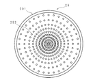
図7は実施の形態1の反射カバー29のドットパターン292の一例を示す模式図である。図7に示すように、ドットパターン292の形状は、円形状であって、適長離隔して同心円状に設けてある。なお、ドットパターン292の形状は、円形状に限定されるものではなく、三角形状、四角形状、五角形状等の多角形状、楕円形状などであってもよい。また、ドットパターン292の配置は同心円状に限定されず、例えば、反射カバー29の形状が長方形又は正方形である場合には、反射カバー29の形状に合わせて、格子状に配置することもできる。また、本実施の形態の照明装置100のように円形状の反射カバー29であってもドットパターンを格子状に配置してもよいし、スクウェア形状の反射カバーであってもドットパターンを同心円状に配置してもよいことは勿論である。つまり、反射カバーの形状によってドットパターンの配置が限定されることはない。
FIG. 7 is a schematic diagram illustrating an example of the
なお、ドットパターン292は、図7の例に限定されない。以下に他の例を示す。図8は実施の形態1の反射カバー29のドットパターン292の第2例を示す模式図である。図8に示すように、ドットパターン292の密度を、反射カバー29の周辺部よりも中央部の方で高くすることができる。つまり、ドットパターン292の密度が、光源であるLEDモジュール2から遠ざかるに従って高くなるように導光部材としてのセンタカバー9に配置してある。反射カバー29内を進行する光が、ドットパターン292が形成された箇所において反射されることで反射カバー29を透過して外部へ放射する方向へ光の進行方向が変化させられる。ドットパターン292の密度が高い方が、反射される光の量が多いので、反射カバー29の周辺部よりも中央部での光の反射量が増加する。従って、反射した箇所での光の放射量が増加する。一方、LEDモジュール2からの光が反射カバー29内部を周辺部から中央部の方へ進行するにつれて光の量は減衰するので、ドットパターン292の密度を周辺部よりも中央部で増やすことにより、反射カバー29の周辺部から中央部にかけての光の放射量を均等にすることができる。
The
図9は実施の形態1の反射カバー29のドットパターン292の第3例を示す模式図である。図9に示すように、ドットパターン292の面積を、反射カバー29の周辺部よりも中央部の方で広くすることができる。つまり、ドットパターン292の面積が、光源であるLEDモジュール2から遠ざかるに従って広くなるように導光部材としてのセンタカバー9に配置してある。ドットパターン292の面積が広い方が、反射される光の量が多いので、反射カバー29の周辺部よりも中央部での光の反射量が増加する。従って、反射した箇所での光の放射量が増加する。一方、LEDモジュール2からの光が反射カバー29内部を周辺部から中央部の方へ進行するにつれて光の量は減衰するので、ドットパターン292の面積を周辺部よりも中央部で増やすことにより、反射カバー29の周辺部から中央部にかけての光の放射量を均等にすることができる。
FIG. 9 is a schematic diagram illustrating a third example of the
図10は実施の形態1のセンタ板8の外観斜視図である。図10に示すように、センタ板8には、センタカバー9を取り付けるため、断面形状が略L字状の固定片81を立設してある。センタ板8は、リモコン等の遠隔操作端末装置からの光を受光する受光部を設けるため、あるいは照明装置100の状態を表示する表示灯を設けるための開口部84を有する。また、センタ板8は、ハーネス61のコネクタを取り付けるための取付部82を有する。
FIG. 10 is an external perspective view of the
照明装置100にセンタカバー9を取り付ける場合、センタカバー9に設けた切片(不図示)を固定片81の位置に合わせ、固定片81の長さ寸法程度センタカバー9を回すことにより、切片を固定片81の隙間に挿入する。
When attaching the
また、センタ板8の適宜の位置にハーネスクリップ等の固定治具を取り付けておき、適長のワイヤ(又は紐)83の一端に設けたリングをハーネスクリップに取り付けるとともに、ワイヤ83の他端に設けたリングをセンタカバー9の適宜の箇所に取り付ける。これにより、センタカバー9を照明装置100に取り付ける際の落下防止を図ることができる。なお、ハーネスクリップ等を設ける代わりに、ワイヤ83の一端側を環状に形成しておき、該環の中に取付アダプタ62からの電源線を通すことによりワイヤ83を照明装置100側に取り付けることもできる。
In addition, a fixing jig such as a harness clip is attached to an appropriate position of the
(実施の形態2)
図11は実施の形態2の照明装置120の構成の要部一例を示す断面図であり、図12は実施の形態2の照明装置120のLEDモジュール52の配置例を示す説明図である。実施の形態1では、センタカバー9の内部へLEDモジュール2からの光を導く構成であったが、実施の形態2では、光源として、主光源としてのLEDモジュール2とLEDモジュール2とは別に補助用の光源としてのLEDモジュール52を設け、LEDモジュール52からの光もセンタカバー9の内部へ導く構成とした点で実施の形態1と異なる。
(Embodiment 2)
FIG. 11 is a cross-sectional view illustrating an example of a main part of the configuration of the
LEDモジュール52は、基板上にLED522を1つ実装してあり、図12に示すように、反射カバー29の周端面291の近傍に周端面291に対向させた状態であって等間隔で4個配置してある。なお、LEDモジュール52、LED522の数又は配置間隔は、一例であって、図11、図12の例に限定されるものではない。
In the
主光源であるLEDモジュール2とは別の補助用の光源としてのLEDモジュール52を備え、センタカバー9(反射カバー29)は、LEDモジュール2だけでなくLEDモジュール52からの光を導いて外部へ放射する。補助用のLEDモジュール52を用いることにより、センタカバー9からの発光量を所望の値にすることができる。例えば、LEDモジュール52の発光量を調整して、透光カバー7からの発光量と同程度の発光量とすることができ、照明装置120の全面で均等の明るさを実現することができる。上記実施の形態2では、LEDモジュール2とLEDモジュール52の両方からの光をセンタカバー9に導く例について説明したが、補助光源であるLEDモジュール52のみからの光をセンタカバー9に導くようにしてもよい。
The
なお、補助用のLEDモジュール52は、常夜灯として用いることもできる。具体的には、LEDモジュール2を消灯した状態でLEDモジュール52のみを点灯させてセンタカバー9の内部に光を導いて、センタカバー9の前面から光を放射させて照明装置120の中央部分が光る常夜灯として用いることができる。
The
上述の実施の形態では、シーリングライトとしての照明装置について説明したが、照明装置は、シーリングライトに限定されるものでなく、他の照明装置であってよい。また、光源としてLEDモジュールを備える照明装置について説明したが、光源はLEDモジュールに限定されるものではなく、EL(Electro-Luminescence)など他の光源でもよい。 In the above-described embodiment, the lighting device as the ceiling light has been described. However, the lighting device is not limited to the ceiling light, and may be another lighting device. Moreover, although the illuminating device provided with the LED module as the light source has been described, the light source is not limited to the LED module, and other light sources such as EL (Electro-Luminescence) may be used.
1 シャーシ
2 LEDモジュール(光源)
5 回路基板(内蔵部品)
7 透光カバー
8 センタ板(覆板)
9 センタカバー(導光部材)
19 反射板
29 反射カバー(導光部材)
292 ドットパターン
52 LEDモジュール(補助用の光源)
1
5 Circuit board (built-in parts)
7
9 Center cover (light guide member)
19
292
Claims (8)
前記非発光部の前面に位置し、前記光源からの光を導いて発光する導光部材を備えることを特徴とする照明装置。 A lighting device including a non-light emitting part on a light transmitting part side that transmits and emits light from a light source,
An illuminating device comprising a light guide member that is positioned in front of the non-light emitting portion and that emits light by guiding light from the light source.
前記光源からの光を透過して発光する透光部と、
前記内蔵部品の前面に位置して前記透光部と並設され、前記光源からの光を導いて発光する導光部材とを備えることを特徴とする照明装置。 A lighting device main body that partitions and accommodates built-in components such as a power supply circuit and a light source;
A light-transmitting part that transmits and emits light from the light source;
An illuminating device comprising: a light guide member that is positioned in front of the built-in component and that is provided in parallel with the light-transmitting portion and that guides light from the light source to emit light.
光を反射して前記導光部材の外部へ放射させる第1の反射部と、
該第1の反射部に対設され、ドットパターンを付した第2の反射部と
を備えることを特徴とする請求項1又は請求項2に記載の照明装置。 The light guide member is
A first reflecting portion that reflects light and emits the light to the outside of the light guide member;
The lighting device according to claim 1, further comprising: a second reflecting portion that is opposed to the first reflecting portion and has a dot pattern.
The illumination device according to any one of claims 1 to 7, wherein the light source includes an auxiliary light source provided to face an end portion of the light guide member on which light enters.
Priority Applications (1)
| Application Number | Priority Date | Filing Date | Title |
|---|---|---|---|
| JP2014235171A JP5918835B2 (en) | 2014-11-20 | 2014-11-20 | Lighting device |
Applications Claiming Priority (1)
| Application Number | Priority Date | Filing Date | Title |
|---|---|---|---|
| JP2014235171A JP5918835B2 (en) | 2014-11-20 | 2014-11-20 | Lighting device |
Related Parent Applications (1)
| Application Number | Title | Priority Date | Filing Date |
|---|---|---|---|
| JP2014116394A Division JP5655170B2 (en) | 2014-06-05 | 2014-06-05 | Lighting device |
Publications (2)
| Publication Number | Publication Date |
|---|---|
| JP2015057791A true JP2015057791A (en) | 2015-03-26 |
| JP5918835B2 JP5918835B2 (en) | 2016-05-18 |
Family
ID=52815792
Family Applications (1)
| Application Number | Title | Priority Date | Filing Date |
|---|---|---|---|
| JP2014235171A Expired - Fee Related JP5918835B2 (en) | 2014-11-20 | 2014-11-20 | Lighting device |
Country Status (1)
| Country | Link |
|---|---|
| JP (1) | JP5918835B2 (en) |
Cited By (4)
| Publication number | Priority date | Publication date | Assignee | Title |
|---|---|---|---|---|
| JP2018510356A (en) * | 2015-03-30 | 2018-04-12 | ジェモロジカル インスティテュート オブ アメリカ インコーポレイテッド(ジーアイエー) | A device for evaluating the optical quality of gemstones |
| JP2019149292A (en) * | 2018-02-27 | 2019-09-05 | パナソニックIpマネジメント株式会社 | Lighting fixture |
| JP2019149287A (en) * | 2018-02-27 | 2019-09-05 | パナソニックIpマネジメント株式会社 | Lighting device |
| JP2020053111A (en) * | 2018-09-21 | 2020-04-02 | パナソニックIpマネジメント株式会社 | Lighting device |
Citations (5)
| Publication number | Priority date | Publication date | Assignee | Title |
|---|---|---|---|---|
| JPH0381907A (en) * | 1989-05-31 | 1991-04-08 | Matsushita Electric Works Ltd | Illuminating fixture for round form fluorescent lamp |
| JPH0982126A (en) * | 1995-09-18 | 1997-03-28 | Toshiba Lighting & Technol Corp | Luminaire |
| JP2003308718A (en) * | 2002-04-12 | 2003-10-31 | Techno Wave Sanwa Kk | Planar luminescent device |
| JP2008293769A (en) * | 2007-05-24 | 2008-12-04 | Stanley Electric Co Ltd | Luminaire |
| JP2009206062A (en) * | 2008-02-29 | 2009-09-10 | Sharp Corp | Lighting device |
-
2014
- 2014-11-20 JP JP2014235171A patent/JP5918835B2/en not_active Expired - Fee Related
Patent Citations (5)
| Publication number | Priority date | Publication date | Assignee | Title |
|---|---|---|---|---|
| JPH0381907A (en) * | 1989-05-31 | 1991-04-08 | Matsushita Electric Works Ltd | Illuminating fixture for round form fluorescent lamp |
| JPH0982126A (en) * | 1995-09-18 | 1997-03-28 | Toshiba Lighting & Technol Corp | Luminaire |
| JP2003308718A (en) * | 2002-04-12 | 2003-10-31 | Techno Wave Sanwa Kk | Planar luminescent device |
| JP2008293769A (en) * | 2007-05-24 | 2008-12-04 | Stanley Electric Co Ltd | Luminaire |
| JP2009206062A (en) * | 2008-02-29 | 2009-09-10 | Sharp Corp | Lighting device |
Cited By (8)
| Publication number | Priority date | Publication date | Assignee | Title |
|---|---|---|---|---|
| JP2018510356A (en) * | 2015-03-30 | 2018-04-12 | ジェモロジカル インスティテュート オブ アメリカ インコーポレイテッド(ジーアイエー) | A device for evaluating the optical quality of gemstones |
| US11280743B2 (en) | 2015-03-30 | 2022-03-22 | Gemological Institute Of America, Inc. (Gia) | Apparatus and method for assessing optical quality of gemstones |
| US11921051B2 (en) | 2015-03-30 | 2024-03-05 | Gemological Institute Of America, Inc. (Gia) | Apparatus and method for assessing optical quality of gemstones |
| JP2019149292A (en) * | 2018-02-27 | 2019-09-05 | パナソニックIpマネジメント株式会社 | Lighting fixture |
| JP2019149287A (en) * | 2018-02-27 | 2019-09-05 | パナソニックIpマネジメント株式会社 | Lighting device |
| JP7029668B2 (en) | 2018-02-27 | 2022-03-04 | パナソニックIpマネジメント株式会社 | lighting equipment |
| JP2020053111A (en) * | 2018-09-21 | 2020-04-02 | パナソニックIpマネジメント株式会社 | Lighting device |
| JP7113372B2 (en) | 2018-09-21 | 2022-08-05 | パナソニックIpマネジメント株式会社 | lighting equipment |
Also Published As
| Publication number | Publication date |
|---|---|
| JP5918835B2 (en) | 2016-05-18 |
Similar Documents
| Publication | Publication Date | Title |
|---|---|---|
| KR101392533B1 (en) | Illumination apparatus | |
| US20120106147A1 (en) | Lighting apparatus | |
| JP2009016095A (en) | Illuminating device and substrate | |
| JP5253552B2 (en) | Lighting device | |
| JP5918835B2 (en) | Lighting device | |
| JP2009087644A (en) | Lighting unit | |
| JP2017050187A (en) | Lighting fixture | |
| JP4902006B2 (en) | Lighting device | |
| JP5559649B2 (en) | Lighting device | |
| JP2016219119A (en) | Led illuminating device | |
| JP5320563B2 (en) | lighting equipment | |
| US20130027971A1 (en) | Dazzle prevention lighting fixture with light guide means to disperse emitted light uniformly | |
| JP2014110119A (en) | Lens and led lighting fixture using the same | |
| JP5116865B2 (en) | Lighting device | |
| JP6025050B2 (en) | Lighting device | |
| JP2009252555A (en) | Lighting system | |
| JP5655170B2 (en) | Lighting device | |
| JP6575620B2 (en) | Lighting device | |
| JP5853128B2 (en) | lighting equipment | |
| JP5506856B2 (en) | Lighting device | |
| JP6034744B2 (en) | Lighting device | |
| JP6300052B2 (en) | Lighting device | |
| JP6807986B2 (en) | LED lighting device | |
| JP2014049275A (en) | Lighting apparatus | |
| JP6086190B2 (en) | Lighting device |
Legal Events
| Date | Code | Title | Description |
|---|---|---|---|
| RD04 | Notification of resignation of power of attorney |
Free format text: JAPANESE INTERMEDIATE CODE: A7424 Effective date: 20150129 |
|
| A977 | Report on retrieval |
Free format text: JAPANESE INTERMEDIATE CODE: A971007 Effective date: 20150820 |
|
| A131 | Notification of reasons for refusal |
Free format text: JAPANESE INTERMEDIATE CODE: A131 Effective date: 20150825 |
|
| A521 | Request for written amendment filed |
Free format text: JAPANESE INTERMEDIATE CODE: A523 Effective date: 20151026 |
|
| TRDD | Decision of grant or rejection written | ||
| A01 | Written decision to grant a patent or to grant a registration (utility model) |
Free format text: JAPANESE INTERMEDIATE CODE: A01 Effective date: 20160315 |
|
| A61 | First payment of annual fees (during grant procedure) |
Free format text: JAPANESE INTERMEDIATE CODE: A61 Effective date: 20160408 |
|
| R150 | Certificate of patent or registration of utility model |
Ref document number: 5918835 Country of ref document: JP Free format text: JAPANESE INTERMEDIATE CODE: R150 |
|
| LAPS | Cancellation because of no payment of annual fees |