JP2015051663A - Fastening structure of fiber reinforced resin frame - Google Patents
Fastening structure of fiber reinforced resin frame Download PDFInfo
- Publication number
- JP2015051663A JP2015051663A JP2013184284A JP2013184284A JP2015051663A JP 2015051663 A JP2015051663 A JP 2015051663A JP 2013184284 A JP2013184284 A JP 2013184284A JP 2013184284 A JP2013184284 A JP 2013184284A JP 2015051663 A JP2015051663 A JP 2015051663A
- Authority
- JP
- Japan
- Prior art keywords
- hole
- frame
- reinforced resin
- fiber reinforced
- resin frame
- Prior art date
- Legal status (The legal status is an assumption and is not a legal conclusion. Google has not performed a legal analysis and makes no representation as to the accuracy of the status listed.)
- Granted
Links
Images

Landscapes
- Connection Of Plates (AREA)
- Standing Axle, Rod, Or Tube Structures Coupled By Welding, Adhesion, Or Deposition (AREA)
Abstract
【課題】繊維強化樹脂フレームを軽量化及び小型化することができる繊維強化樹脂フレームの締結構造を提供する。【解決手段】繊維強化樹脂フレーム50は、第1部材51と、第1部材51に積層して接着される第2部材52と、を有し、第1部材51は、他のフレーム14と第2部材52との間に配置され、板厚方向に貫通する第1貫通孔61を備え、第1貫通孔61にカラー部材70が嵌装され、第1貫通孔61とカラー部材70の外周面71が接着され、第2部材52は、板厚方向に貫通し、第1貫通孔61より小径の第2貫通孔62を備え、第2部材52の第2貫通孔62の周囲の内面52bにカラー部材70の一端面73が直接当接し、ボルト40は、第2貫通孔62とカラー部材70に形成される中空部72を貫通して、繊維強化樹脂フレーム50を他のフレーム14に締結する。【選択図】図5A fiber reinforced resin frame fastening structure capable of reducing the weight and size of a fiber reinforced resin frame. A fiber reinforced resin frame includes a first member and a second member that is laminated and bonded to the first member. The first member includes a second member and a second member. The first through hole 61 is disposed between the two members 52 and penetrates in the plate thickness direction. The collar member 70 is fitted into the first through hole 61, and the first through hole 61 and the outer peripheral surface of the color member 70. 71 is bonded, and the second member 52 has a second through hole 62 penetrating in the plate thickness direction and having a smaller diameter than the first through hole 61, and is formed on the inner surface 52 b around the second through hole 62 of the second member 52. One end surface 73 of the collar member 70 directly contacts, and the bolt 40 passes through the second through hole 62 and the hollow portion 72 formed in the collar member 70 to fasten the fiber reinforced resin frame 50 to the other frame 14. . [Selection] Figure 5
Description
本発明は、繊維強化樹脂フレームの締結構造に関し、特に、ボルト締結される繊維強化樹脂フレームの締結構造に関する。 The present invention relates to a fastening structure for a fiber reinforced resin frame, and more particularly to a fastening structure for a fiber reinforced resin frame to be bolted.
従来、熱可塑性の繊維強化樹脂からなるインナボディとアウタボディとを熱溶着してリアボディを形成し、このリアボディをブラケットを介して車体フレームにボルトで固定する自動二輪車のリアボディ構造が開示されている(例えば、特許文献1参照)。 Conventionally, there has been disclosed a rear body structure of a motorcycle in which an inner body and an outer body made of thermoplastic fiber reinforced resin are thermally welded to form a rear body, and the rear body is fixed to a vehicle body frame with a bolt via a bracket ( For example, see Patent Document 1).
ところで、特許文献1に記載の自動二輪車のリアボディ構造によると、ブラケットを介してリアボディを車体フレームにボルト固定するので、専用のブラケットが必要であり、部品点数が増加して軽量化や小型化がし難く、また、製作コストが増加してしまっていた。 By the way, according to the rear body structure of the motorcycle described in Patent Document 1, since the rear body is bolted to the vehicle body frame via the bracket, a dedicated bracket is required, and the number of parts increases, resulting in a reduction in weight and size. It was difficult, and the production cost was increasing.
本発明は、前述した事情に鑑みてなされたものであり、その目的は、繊維強化樹脂フレームを軽量化及び小型化することができる繊維強化樹脂フレームの締結構造を提供することにある。 This invention is made | formed in view of the situation mentioned above, The objective is to provide the fastening structure of the fiber reinforced resin frame which can reduce in weight and size of a fiber reinforced resin frame.
上記目的を達成するために、請求項1に係る発明は、鞍乗型車両の車体フレームの一部を構成し、他のフレームにボルトで締結される繊維強化樹脂フレームの締結構造であって、繊維強化樹脂フレームは、第1部材と、第1部材に積層して接着される第2部材と、を有し、第1部材は、他のフレームと第2部材との間に配置され、板厚方向に貫通する第1貫通孔を備え、第1貫通孔にカラー部材が嵌装され、第1貫通孔とカラー部材の外周面が接着され、第2部材は、板厚方向に貫通し、第1貫通孔より小径の第2貫通孔を備え、第2部材の第2貫通孔の周囲の内面にカラー部材の一端面が直接当接し、ボルトは、第2貫通孔とカラー部材に形成される中空部を貫通して、繊維強化樹脂フレームを他のフレームに締結することを特徴とする。 In order to achieve the above object, the invention according to claim 1 is a fastening structure of a fiber reinforced resin frame that constitutes a part of a body frame of a saddle-ride type vehicle and is fastened to another frame with a bolt, The fiber reinforced resin frame has a first member and a second member laminated and bonded to the first member, the first member being disposed between the other frame and the second member, A first through hole penetrating in the thickness direction is provided, a collar member is fitted in the first through hole, the first through hole and the outer peripheral surface of the color member are bonded, and the second member penetrates in the plate thickness direction, A second through hole having a smaller diameter than the first through hole is provided, and one end surface of the collar member is in direct contact with the inner surface around the second through hole of the second member, and the bolt is formed in the second through hole and the collar member. The fiber reinforced resin frame is fastened to another frame through the hollow portion.
請求項2に係る発明は、請求項1の構成に加えて、第2部材とボルトの頭部との間に配置されるフランジ部材を更に備え、フランジ部材は、第2部材の板厚以下の高さを有し第2貫通孔に嵌装される小径部と、第1貫通孔より大径とされて小径部から連続形成される大径部と、を有することを特徴とする。 The invention according to claim 2 further includes a flange member disposed between the second member and the head of the bolt in addition to the configuration of claim 1, and the flange member has a thickness equal to or less than the plate thickness of the second member. A small-diameter portion that has a height and is fitted into the second through-hole, and a large-diameter portion that has a larger diameter than the first through-hole and is continuously formed from the small-diameter portion.
請求項3に係る発明は、請求項1又は2の構成に加えて、第1部材、第2部材、及びカラー部材の各接着部に使用される接着剤がウレタン系接着剤であることを特徴とする。 The invention according to claim 3 is characterized in that, in addition to the configuration of claim 1 or 2, the adhesive used for each bonding portion of the first member, the second member, and the collar member is a urethane-based adhesive. And
請求項4に係る発明は、請求項1〜3のいずれか1項の構成に加えて、カラー部材の外周面は、第1貫通孔に嵌合して第1貫通孔に対するカラー部材の位置決めを行う位置出し面と、位置出し面から軸方向外側に向かうに従って縮径するテーパー面と、を有し、第1貫通孔とテーパー面との隙間に、ウレタン系接着剤が配置されることを特徴とする。 In the invention according to claim 4, in addition to the configuration of any one of claims 1 to 3, the outer peripheral surface of the collar member is fitted into the first through hole to position the collar member with respect to the first through hole. A positioning surface to be performed and a tapered surface having a diameter that decreases from the positioning surface toward the outside in the axial direction, and a urethane-based adhesive is disposed in a gap between the first through hole and the tapered surface. And
請求項5に係る発明は、請求項1〜3のいずれか1項の構成に加えて、第1貫通孔に、径方向内側に向かって突出する複数の凸部が形成され、カラー部材の外周面は円筒状に形成され、複数の凸部によって中心位置出しされることを特徴とする。 According to a fifth aspect of the present invention, in addition to the configuration of any one of the first to third aspects, a plurality of convex portions projecting radially inward are formed in the first through hole, and the outer periphery of the collar member The surface is formed in a cylindrical shape and is centered by a plurality of convex portions.
請求項6に係る発明は、請求項1〜5のいずれか1項の構成に加えて、第2部材の内面にウレタン系接着剤を塗布した後、カラー部材の一端面が直接当接する第2部材の当接面に塗布されたウレタン系接着剤を剥離することで、当接面からウレタン系接着剤を除去することを特徴とする。 According to a sixth aspect of the present invention, in addition to the configuration of any one of the first to fifth aspects, the second adhesive member directly contacts one end surface of the collar member after applying a urethane adhesive to the inner surface of the second member. By removing the urethane adhesive applied to the contact surface of the member, the urethane adhesive is removed from the contact surface.
請求項1の発明によれば、繊維強化樹脂フレームは、第1部材と、第1部材に積層して接着される第2部材と、を有し、第1部材は、他のフレームと第2部材との間に配置され、板厚方向に貫通する第1貫通孔を備え、第1貫通孔にカラー部材が嵌装され、第1貫通孔とカラー部材の外周面が接着され、第2部材は、板厚方向に貫通し、第1貫通孔より小径の第2貫通孔を備え、第2部材の第2貫通孔の周囲の内面にカラー部材の一端面が直接当接し、ボルトは、第2貫通孔とカラー部材に形成される中空部を貫通して、繊維強化樹脂フレームを他のフレームに締結する。このため、従来のような繊維強化樹脂フレームを他のフレームに取り付けるためのブラケットを別途設ける必要がないので、繊維強化樹脂フレームを軽量化及び小型化することができる。また、第2部材の第2貫通孔の周囲の内面にカラー部材の一端面が直接当接するため、繊維強化樹脂フレームと他のフレームとの間に、接着剤などの寸法変化の可能性のある部材が存在しない。このため、繊維強化樹脂フレームの板厚方向の寸法精度を向上することができると共に、接着剤が溶けるなどしてボルト締結の軸力が変化するのを防止することができる。 According to the invention of claim 1, the fiber reinforced resin frame has the first member and the second member laminated and bonded to the first member, and the first member is the second frame and the second member. A first through-hole that is disposed between the first through-hole and extends in the plate thickness direction, the collar member is fitted into the first through-hole, and the outer periphery of the first through-hole and the color member is bonded to the second member. Is provided with a second through hole having a smaller diameter than the first through hole, with one end surface of the collar member directly contacting the inner surface around the second through hole of the second member, 2 The fiber reinforced resin frame is fastened to another frame through the through hole and the hollow portion formed in the collar member. For this reason, there is no need to separately provide a bracket for attaching the conventional fiber reinforced resin frame to another frame, so that the fiber reinforced resin frame can be reduced in weight and size. In addition, since one end surface of the collar member directly contacts the inner surface around the second through hole of the second member, there is a possibility of dimensional change such as an adhesive between the fiber reinforced resin frame and another frame. There is no member. For this reason, it is possible to improve the dimensional accuracy of the fiber reinforced resin frame in the plate thickness direction, and it is possible to prevent the axial force of the bolt fastening from changing due to melting of the adhesive or the like.
請求項2の発明によれば、第2部材とボルトの頭部との間に配置されるフランジ部材を更に備え、フランジ部材は、第2部材の板厚以下の高さを有し第2貫通孔に嵌装される小径部と、第1貫通孔より大径とされて小径部から連続形成される大径部と、を有するため、大径部と第2部材との当接面積を広くすることができ、繊維強化樹脂フレームに作用するボルト締結応力を分散することができる。さらに、大径部が第1貫通孔より大径に設定されているので、第1貫通孔とカラー部材の外周面との接着剤層に作用するボルト締結応力を分散することができ、接着剤層を保護することができる。 According to invention of Claim 2, it further has a flange member arrange | positioned between the 2nd member and the head part of a volt | bolt, and a flange member has the height below the plate | board thickness of a 2nd member, and is 2nd penetration. Since it has a small-diameter portion fitted in the hole and a large-diameter portion that is larger in diameter than the first through-hole and is continuously formed from the small-diameter portion, the contact area between the large-diameter portion and the second member is widened. The bolt fastening stress acting on the fiber reinforced resin frame can be dispersed. Furthermore, since the large diameter portion is set to be larger in diameter than the first through hole, the bolt fastening stress acting on the adhesive layer between the first through hole and the outer peripheral surface of the collar member can be dispersed, and the adhesive The layer can be protected.
請求項3の発明によれば、第1部材、第2部材、及びカラー部材の各接着部に使用される接着剤がウレタン系接着剤であるため、ウレタン系接着剤は硬度が比較的低く、第1部材、第2部材、及びカラー部材の各接着面に対する追従性を向上することができ、また、ウレタン系接着剤の接着剤層により振動を吸収することができる。 According to invention of Claim 3, since the adhesive agent used for each adhesion part of the 1st member, the 2nd member, and the color member is a urethane adhesive, the urethane adhesive has a relatively low hardness, The followability of the first member, the second member, and the color member with respect to the bonding surfaces can be improved, and vibration can be absorbed by the adhesive layer of the urethane-based adhesive.
請求項4の発明によれば、カラー部材の外周面は、第1貫通孔に嵌合して第1貫通孔に対するカラー部材の位置決めを行う位置出し面と、位置出し面から軸方向外側に向かうに従って縮径するテーパー面と、を有し、第1貫通孔とテーパー面との隙間に、ウレタン系接着剤が配置されるため、カラー部材と第1貫通孔との位置決めを行いつつカラー部材を第1貫通孔に接着することができ、繊維強化樹脂フレームの製造工程を簡易化することができる。 According to the invention of claim 4, the outer peripheral surface of the collar member is fitted to the first through hole to position the collar member with respect to the first through hole, and from the positioning surface to the outside in the axial direction. And the urethane adhesive is disposed in the gap between the first through hole and the tapered surface, so that the collar member is positioned while positioning the collar member and the first through hole. It can adhere to the 1st penetration hole, and can simplify the manufacturing process of a fiber reinforced resin frame.
請求項5の発明によれば、第1貫通孔に、径方向内側に向かって突出する複数の凸部が形成され、カラー部材の外周面は円筒状に形成され、複数の凸部によって中心位置出しされるため、簡素な構造でカラー部材の位置合わせを行うことができ、繊維強化樹脂フレームの製造工程を簡易化することができる。 According to the invention of claim 5, the first through hole is formed with a plurality of convex portions projecting radially inward, and the outer peripheral surface of the collar member is formed in a cylindrical shape, and the central position is formed by the plurality of convex portions. Therefore, the color member can be aligned with a simple structure, and the manufacturing process of the fiber-reinforced resin frame can be simplified.
請求項6の発明によれば、第2部材の内面にウレタン系接着剤を塗布した後、カラー部材の一端面が直接当接する第2部材の当接面に塗布されたウレタン系接着剤を剥離することで、当接面からウレタン系接着剤を除去するため、ウレタン系接着剤の塗布工程を簡素化することができる。 According to invention of Claim 6, after apply | coating a urethane type adhesive agent to the inner surface of a 2nd member, the urethane type adhesive agent apply | coated to the contact surface of the 2nd member which the one end surface of a color member directly contacts is peeled. By doing so, since the urethane adhesive is removed from the contact surface, the application process of the urethane adhesive can be simplified.
以下、本発明の実施の形態を、添付図面に基づいて説明する。なお、図面は符号の向きに見るものとし、以下の説明において、前後、左右、上下は、操縦者から見た方向に従い、図面に車両の前方をFr、後方をRr、左側をL、右側をR、上方をU、下方をD、として示す。 Hereinafter, embodiments of the present invention will be described with reference to the accompanying drawings. It should be noted that the drawings are viewed in the direction of the reference numerals, and in the following description, front, rear, left and right, and top and bottom are in accordance with the direction seen from the operator, and the front of the vehicle is Fr, rear is Rr, left is L, and right is R, upper is shown as U, and lower is shown as D.
本実施形態の自動二輪車(鞍乗型車両)10は、図1に示すように、車体フレーム11を、前端に設けられるヘッドパイプ12と、ヘッドパイプ12から左右に分かれて後ろ下がりに延びる左右一対のメインフレーム13と、左右一対のメインフレーム13の後端部に連結され下方に延びる左右一対のピボットフレーム14と、ヘッドパイプ12から下方に延びるダウンフレーム15と、ダウンフレーム15の下端部と左右一対のピボットフレーム14の下端部とを連結する左右一対のボトムフレーム16と、から構成し、ピボットフレーム14及びボトムフレーム16にエンジン30が取り付けられる。
As shown in FIG. 1, a motorcycle (saddle-type vehicle) 10 of this embodiment includes a
また、自動二輪車10は、ヘッドパイプ12に操向自在に支持されるフロントフォーク21と、フロントフォーク21の下端部に回転可能に支持される前輪WFと、フロントフォーク21の上端部に取り付けられる操舵用のハンドル22と、ピボットフレーム14に揺動自在に支持されるスイングアーム23と、スイングアーム23の後端部に回転可能に支持される後輪WRと、スイングアーム23を懸架する不図示の後輪懸架装置と、メインフレーム13に取り付けられる燃料タンク24と、を備える。
The
また、左右一対のピボットフレーム14には、本発明に係る繊維強化樹脂で製作されたリアフレーム50がボルト締結されている。リアフレーム50には、リヤフェンダ37、マフラーカバー38、乗員用シート39が固定されている。なお、本実施形態のリアフレーム50については後に詳述する。
A
エンジン30は、図1に示すように、その外殻は、主に、クランクケース31と、クランクケース31の前方上端部に取り付けられるシリンダブロック32と、シリンダブロック32の上端部に取り付けられるシリンダヘッド33と、シリンダヘッド33の上部開口を覆うシリンダヘッドカバー34と、から構成されている。
As shown in FIG. 1, the outer shell of the
シリンダヘッド33には、不図示のスロットルボディ及びエアクリーナケースが接続されている。また、シリンダヘッド33には、排気管35と、排気管35の下流端に取り付けられて排気音を低減するマフラー36と、が接続されている。
The
また、図1に示すように、左右一対のピボットフレーム14の上端部及び中間部後面には、雌ねじ14s(図5参照)を有する左右一対の取付ブラケット14aがそれぞれ形成されており、この上下左右4ヶ所の取付ブラケット14aの車幅方向外側面にリアフレーム50がボルト40により締結されている(図4参照)。
Further, as shown in FIG. 1, a pair of left and
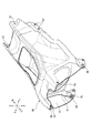
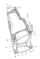
リアフレーム50は、図2〜図4に示すように、内側部分を構成するインナーフレーム(第1部材)51と、外側部分を構成するアウターフレーム(第2部材)52と、を接合したモノコック構造のフレームであり、車体フレーム11の一部を構成する。また、インナーフレーム51とアウターフレーム52は、ガラス繊維、炭素繊維、及びスチール繊維などで強度補強された繊維強化樹脂によりそれぞれ形成されている。
As shown in FIGS. 2 to 4, the
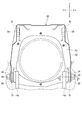
また、リアフレーム50は、インナーフレーム51の外側にアウターフレーム52が積層されて、図3に示す接着領域(網掛け部)55にウレタン系接着剤UAが塗布されて接着されている。換言すると、インナーフレーム51の外面51aとアウターフレーム52の内面52aがウレタン系接着剤UAにより接着されている。従って、インナーフレーム51は、ピボットフレーム14の取付ブラケット14aとアウターフレーム52との間に配置されている(図5参照)。なお、図3では、図面の理解を容易にするため、車両左側の接着領域55のみを示しているが、車両右側にも同様の接着領域55が設けられる。
The
そして、リアフレーム50の前端部(図2及び図3の左端部)には、左右一対のピボットフレーム14の4ヶ所の取付ブラケット14aにそれぞれ締結される4ヶ所の締結部56が設けられている。また、リアフレーム50の後端部(図2及び図3の右端部)には、リヤフェンダ37やマフラーカバー38などを取り付けるためのボルト挿通穴57が複数形成されている。
Then, at the front end portion (the left end portion in FIGS. 2 and 3) of the
次に、本実施形態の繊維強化樹脂フレームの締結構造である上記した4ヶ所の締結部56の構造について説明する。なお、4ヶ所の締結部56の構造は、いずれも同様であるので、車両左下部の締結部56(図4の右下の締結部56)を例にして説明する。
Next, the structure of the above-described four
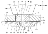
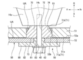
インナーフレーム51は、図5に示すように、板厚方向に貫通して形成される第1貫通孔61を有し、この第1貫通孔61に円筒状のカラー部材70が嵌装されている。そして、第1貫通孔61とカラー部材70の外周面71が、ウレタン系接着剤UAにより接着されている。また、カラー部材70の軸中心には、ボルト40を挿通するためのボルト挿通穴(中空部)72が貫通して設けられている。
As shown in FIG. 5, the
アウターフレーム52は、板厚方向に貫通する第2貫通孔62を備える。この第2貫通孔62は、第1貫通孔61と同心、且つ第1貫通孔61より小径に形成されている。
The
また、本実施形態では、上述したように、インナーフレーム51の外面51aとアウターフレーム52の内面52aが、ウレタン系接着剤UAにより接着されると共に、第1貫通孔61とカラー部材70の外周面71が、ウレタン系接着剤UAにより接着されているが、カラー部材70の一端面73が直接当接する第2貫通孔62の周囲の内面である当接面52bに塗布されたウレタン系接着剤UAが除去されており、当接面52bにはカラー部材70の一端面73が直接当接している。また、カラー部材70の他端面74は、インナーフレーム51より僅かに車両内側に突出して、取付ブラケット14aの外側面に直接当接している。
In the present embodiment, as described above, the
そして、ウレタン系接着剤UAが除去されたアウターフレーム52の当接面52bの形成は、例えば、アウターフレーム52の内面52aの全面にウレタン系接着剤UAを塗布した後、カラー部材70の一端面73が直接当接するアウターフレーム52の当接面52bに塗布されたウレタン系接着剤UAを剥離することにより行われる。より具体的には、ウレタン系接着剤UAの塗布前にアウターフレーム52の当接面52bにマスキングテープを貼り付けて、ウレタン系接着剤UAの塗布後にそのマスキングテープを剥がすことにより行われる。このため、アウターフレーム52の内面52aの当接面52b以外の部分にウレタン系接着剤UAを塗布するという煩瑣な作業を行う必要がないので、ウレタン系接着剤UAの塗布工程が簡素化される。
The
また、図5に示すように、アウターフレーム52とボルト40の頭部との間にはフランジ部材80が配置されており、このフランジ部材80は、アウターフレーム52の板厚Tと同じ高さHを有し、アウターフレーム52の第2貫通孔62に嵌装される小径部81と、インナーフレーム51の第1貫通孔61より大径とされて小径部81から連続形成される大径部82と、フランジ部材80の軸中心に形成され、ボルト40が挿通されるボルト挿通穴83と、を有する。なお、小径部81の高さHは、アウターフレーム52の板厚Tと同じに限定されず、板厚T以下(板厚T≧高さH)であればよく、例えば、板厚Tより小さくてもよい。
Further, as shown in FIG. 5, a
このように構成された締結部56では、フランジ部材80の小径部81を車幅方向外側からアウターフレーム52の第2貫通孔62に嵌合させた後、ボルト40をフランジ部材80のボルト挿通穴83及びカラー部材70のボルト挿通穴72に挿通させると共に、ボルト40を取付ブラケット14aの雌ねじ14sに螺合させることにより、リアフレーム50が取付ブラケット14aに締結される。
In the
以上説明したように、本実施形態の繊維強化樹脂フレームの締結構造によれば、インナーフレーム51と、インナーフレーム51に積層して接着されるアウターフレーム52と、を有し、インナーフレーム51は、板厚方向に貫通する第1貫通孔61を備え、第1貫通孔61にカラー部材70が嵌装され、第1貫通孔61とカラー部材70の外周面71が接着され、アウターフレーム52は、板厚方向に貫通し、第1貫通孔61より小径の第2貫通孔62を備え、アウターフレーム52の第2貫通孔62の周囲の内面である当接面52bにカラー部材70の一端面73が直接当接し、ボルト40は、第2貫通孔62とカラー部材70のボルト挿通穴72を貫通して、リアフレーム50をピボットフレーム14の取付ブラケット14aに締結する。このため、従来のようなリアフレームを他のフレームに取り付けるためのブラケットを別途設ける必要がないので、リアフレーム50を軽量化及び小型化することができる。また、アウターフレーム52の当接面52bにカラー部材70の一端面73が直接当接するため、リアフレーム50と取付ブラケット14aとの間に、接着剤などの寸法変化の可能性のある部材が存在しない。このため、リアフレーム50の板厚方向の寸法精度を向上することができると共に、接着剤が溶けるなどしてボルト締結の軸力が変化するのを防止することができる。
As described above, according to the fastening structure of the fiber reinforced resin frame of the present embodiment, the
また、本実施形態の繊維強化樹脂フレームの締結構造によれば、フランジ部材80が、アウターフレーム52の板厚T以下の高さHを有しアウターフレーム52の第2貫通孔62に嵌装される小径部81と、インナーフレーム51の第1貫通孔61より大径とされて小径部81から連続形成される大径部82と、を有するため、大径部82とアウターフレーム52との当接面積を広くすることができ、リアフレーム50に作用するボルト締結応力を分散することができる。さらに、大径部82が第1貫通孔61より大径に設定されているので、第1貫通孔61とカラー部材70の外周面71との接着剤層に作用するボルト締結応力を分散することができ、接着剤層を保護することができる。
Further, according to the fastening structure of the fiber reinforced resin frame of the present embodiment, the
また、本実施形態の繊維強化樹脂フレームの締結構造によれば、インナーフレーム51、アウターフレーム52、及びカラー部材70の各接着部に使用される接着剤がウレタン系接着剤UAであるため、ウレタン系接着剤は硬度が比較的低く、インナーフレーム51、アウターフレーム52、及びカラー部材70の各接着面に対する追従性を向上することができ、また、ウレタン系接着剤UAの接着剤層により振動を吸収することができる。
Moreover, according to the fastening structure of the fiber reinforced resin frame of this embodiment, since the adhesive used for each adhesive part of the
また、本実施形態の繊維強化樹脂フレームの締結構造によれば、アウターフレーム52の内面52aにウレタン系接着剤UAを塗布した後、カラー部材70の一端面73が直接当接するアウターフレーム52の当接面52bに塗布されたウレタン系接着剤UAを剥離することで、当接面52bからウレタン系接着剤UAを除去するため、ウレタン系接着剤UAの塗布工程を簡素化することができる。
Further, according to the fastening structure of the fiber reinforced resin frame of the present embodiment, after applying the urethane adhesive UA to the
なお、本実施形態の第1変形例として、図6に示すように、カラー部材70の外周面71が、インナーフレーム51の第1貫通孔61に嵌合して第1貫通孔61に対するカラー部材70の位置決めを行う位置出し面71aと、位置出し面71aから軸方向外側に向かうに従って縮径するテーパー面71bと、を有していてもよい。この場合、第1貫通孔61とテーパー面71bとの隙間に、ウレタン系接着剤UAが配置される。なお、この場合、カラー部材70は、テーパー面71bが取付ブラケット14a側となるように使用される。
As a first modification of the present embodiment, as shown in FIG. 6, the outer
そして、本変形例によれば、カラー部材70の外周面71が、インナーフレーム51の第1貫通孔61に嵌合して第1貫通孔61に対するカラー部材70の位置決めを行う位置出し面71aと、位置出し面71aから軸方向外側に向かうに従って縮径するテーパー面71bと、を有し、第1貫通孔61とテーパー面71bとの隙間に、ウレタン系接着剤UAが配置されるため、カラー部材70と第1貫通孔61との位置決めを行いつつカラー部材70を第1貫通孔61に接着することができ、リアフレーム50の製造工程を簡易化することができる。
According to this modification, the outer
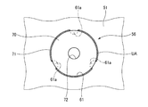
また、本実施形態の第2変形例として、図7に示すように、インナーフレーム51の第1貫通孔61に、径方向内側に向かって突出し且つ軸方向に延びる断面円弧状の凸条(凸部)61aが周方向等間隔に3個形成され、カラー部材70の外周面71が、上記3個の凸条61aによって第1貫通孔61の中心とカラー部材70のボルト挿通穴72の中心が一致するように位置出しされてもよい。また、第1貫通孔61とカラー部材70の外周面71との隙間にウレタン系接着剤UAを入れてもよい。この場合、第1貫通孔61の3個の凸条61aにより、カラー部材70と第1貫通孔61との位置決めが行われる。また、カラー部材70は、3個の凸条61aを潰すようにして第1貫通孔61に挿入される。また、ウレタン系接着剤UAの接着剤層によりカラー部材70の周方向の回転が規制される。なお、凸条61aの個数は任意である。
Further, as a second modification of the present embodiment, as shown in FIG. 7, the first through-
そして、本変形例によれば、インナーフレーム51の第1貫通孔61に、径方向内側に向かって突出する3個の凸条61aが周方向等間隔に形成され、カラー部材70の外周面71が、3個の凸条61aによって中心位置出しされるため、簡素な構造でカラー部材70の位置合わせを行うことができ、リアフレーム50の製造工程を簡易化することができる。
According to this modification, the three protruding
なお、本発明は上記実施形態に例示したものに限定されるものではなく、本発明の要旨を逸脱しない範囲において適宜変更可能である。 In addition, this invention is not limited to what was illustrated to the said embodiment, In the range which does not deviate from the summary of this invention, it can change suitably.
10 自動二輪車(鞍乗型車両)
11 車体フレーム
14 ピボットフレーム(他のフレーム)
14a 取付ブラケット
40 ボルト
50 リアフレーム(繊維強化樹脂フレーム)
51 インナーフレーム(第1部材)
52 アウターフレーム(第2部材)
52a 内面
52b 当接面(第2貫通孔の周囲の内面)
56 締結部
61 第1貫通孔
61a 凸条(凸部)
62 第2貫通孔
70 カラー部材
71 外周面
71a 位置出し面
71b テーパー面
72 ボルト挿通穴(中空部)
73 一端面
80 フランジ部材
81 小径部
82 大径部
UA ウレタン系接着剤
H 高さ
T 板厚
10 Motorcycle (saddle-ride type vehicle)
11
51 Inner frame (first member)
52 Outer frame (second member)
52a
56
62 2nd through-
73 One
Claims (6)
前記繊維強化樹脂フレーム(50)は、第1部材(51)と、前記第1部材(51)に積層して接着される第2部材(52)と、を有し、
前記第1部材(51)は、前記他のフレーム(14)と前記第2部材(52)との間に配置され、板厚方向に貫通する第1貫通孔(61)を備え、
前記第1貫通孔(61)にカラー部材(70)が嵌装され、前記第1貫通孔(61)と前記カラー部材(70)の外周面(71)が接着され、
前記第2部材(52)は、板厚方向に貫通し、前記第1貫通孔(61)より小径の第2貫通孔(62)を備え、
前記第2部材(52)の前記第2貫通孔(62)の周囲の内面(52b)に前記カラー部材(70)の一端面(73)が直接当接し、
前記ボルト(40)は、前記第2貫通孔(62)と前記カラー部材(70)に形成される中空部(72)を貫通して、前記繊維強化樹脂フレーム(50)を前記他のフレーム(14)に締結することを特徴とする繊維強化樹脂フレーム(50)の締結構造。 A fastening structure of a fiber reinforced resin frame (50) that constitutes a part of the body frame (11) of the saddle riding type vehicle (10) and is fastened to the other frame (14) with a bolt (40),
The fiber reinforced resin frame (50) includes a first member (51) and a second member (52) that is laminated and bonded to the first member (51).
The first member (51) is disposed between the other frame (14) and the second member (52), and includes a first through hole (61) penetrating in the plate thickness direction.
A collar member (70) is fitted into the first through hole (61), and an outer peripheral surface (71) of the first through hole (61) and the collar member (70) is bonded,
The second member (52) includes a second through hole (62) penetrating in the plate thickness direction and having a smaller diameter than the first through hole (61),
One end surface (73) of the collar member (70) directly contacts the inner surface (52b) around the second through hole (62) of the second member (52),
The bolt (40) passes through the hollow portion (72) formed in the second through hole (62) and the collar member (70), and the fiber reinforced resin frame (50) is connected to the other frame ( 14) A fastening structure of a fiber-reinforced resin frame (50), characterized by being fastened to 14).
前記フランジ部材(80)は、前記第2部材(52)の板厚(T)以下の高さ(H)を有し前記第2貫通孔(62)に嵌装される小径部(81)と、前記第1貫通孔(61)より大径とされて前記小径部(81)から連続形成される大径部(82)と、を有することを特徴とする請求項1に記載の繊維強化樹脂フレーム(50)の締結構造。 A flange member (80) disposed between the second member (52) and the head of the bolt (40);
The flange member (80) has a small diameter portion (81) having a height (H) equal to or less than a plate thickness (T) of the second member (52) and fitted in the second through hole (62). The fiber reinforced resin according to claim 1, further comprising a large diameter portion (82) having a larger diameter than the first through hole (61) and continuously formed from the small diameter portion (81). Fastening structure of the frame (50).
前記第1貫通孔(61)と前記テーパー面(71b)との隙間に、前記ウレタン系接着剤(UA)が配置されることを特徴とする請求項1〜3のいずれか1項に記載の繊維強化樹脂フレーム(50)の締結構造。 An outer peripheral surface (71) of the collar member (70) is fitted to the first through hole (61) to position the collar member (70) with respect to the first through hole (61) ( 71a), and a tapered surface (71b) whose diameter decreases from the positioning surface (71a) toward the outside in the axial direction,
The urethane type adhesive (UA) is arrange | positioned in the clearance gap between the said 1st through-hole (61) and the said taper surface (71b), The any one of Claims 1-3 characterized by the above-mentioned. Fastening structure of fiber reinforced resin frame (50).
前記カラー部材(70)の外周面は円筒状に形成され、前記複数の凸部(61a)によって中心位置出しされることを特徴とする請求項1〜3のいずれか1項に記載の繊維強化樹脂フレーム(50)の締結構造。 In the first through hole (61), a plurality of convex portions (61a) projecting radially inward are formed,
The fiber reinforcement according to any one of claims 1 to 3, wherein an outer peripheral surface of the collar member (70) is formed in a cylindrical shape and is centered by the plurality of convex portions (61a). Fastening structure of resin frame (50).
Priority Applications (1)
| Application Number | Priority Date | Filing Date | Title |
|---|---|---|---|
| JP2013184284A JP6122741B2 (en) | 2013-09-05 | 2013-09-05 | Fastening structure of fiber reinforced resin frame |
Applications Claiming Priority (1)
| Application Number | Priority Date | Filing Date | Title |
|---|---|---|---|
| JP2013184284A JP6122741B2 (en) | 2013-09-05 | 2013-09-05 | Fastening structure of fiber reinforced resin frame |
Publications (2)
| Publication Number | Publication Date |
|---|---|
| JP2015051663A true JP2015051663A (en) | 2015-03-19 |
| JP6122741B2 JP6122741B2 (en) | 2017-04-26 |
Family
ID=52701046
Family Applications (1)
| Application Number | Title | Priority Date | Filing Date |
|---|---|---|---|
| JP2013184284A Expired - Fee Related JP6122741B2 (en) | 2013-09-05 | 2013-09-05 | Fastening structure of fiber reinforced resin frame |
Country Status (1)
| Country | Link |
|---|---|
| JP (1) | JP6122741B2 (en) |
Cited By (5)
| Publication number | Priority date | Publication date | Assignee | Title |
|---|---|---|---|---|
| JP2017125604A (en) * | 2015-12-10 | 2017-07-20 | ゼネラル・エレクトリック・カンパニイ | Metal mounting system integrated in composite structures |
| WO2019112006A1 (en) * | 2017-12-08 | 2019-06-13 | 本田技研工業株式会社 | Body frame structure |
| JP2019178761A (en) * | 2018-03-30 | 2019-10-17 | 株式会社ホンダアクセス | Fixing structure |
| US10727648B2 (en) | 2018-05-31 | 2020-07-28 | Nichia Corporation | Light source device |
| DE102020101714A1 (en) | 2019-02-04 | 2020-08-06 | Suzuki Motor Corporation | Edge structure of a structural body made of fiber-reinforced resin |
Citations (14)
| Publication number | Priority date | Publication date | Assignee | Title |
|---|---|---|---|---|
| JPS58209672A (en) * | 1982-05-28 | 1983-12-06 | 本田技研工業株式会社 | Car body frame |
| JPS60131710U (en) * | 1984-02-13 | 1985-09-03 | 三菱電機株式会社 | Fastening structure of reinforced plastic plate |
| JPS63154806U (en) * | 1987-03-31 | 1988-10-12 | ||
| US4900048A (en) * | 1987-10-02 | 1990-02-13 | Gleb Derujinsky | Integral seamless composite bicycle frame |
| JPH07215256A (en) * | 1994-02-07 | 1995-08-15 | Yamaha Motor Co Ltd | Rear body structure of motorcycle |
| JP2001213377A (en) * | 2000-02-03 | 2001-08-07 | Honda Motor Co Ltd | Motorcycle frame |
| JP2001263314A (en) * | 2000-03-17 | 2001-09-26 | Honda Motor Co Ltd | Bolt fastening structure of magnesium alloy member |
| JP2001278162A (en) * | 2000-03-31 | 2001-10-10 | Miyata Ind Co Ltd | Method of jointing frame pipe for bicycle |
| JP2004225802A (en) * | 2003-01-22 | 2004-08-12 | Keikyu Faintekku:Kk | Plate material fastener and plate material fastening method |
| WO2005068284A1 (en) * | 2004-01-13 | 2005-07-28 | Toray Industries, Inc. | Crank for bicycle and method of producing the same |
| JP2007332975A (en) * | 2006-06-12 | 2007-12-27 | Toyota Motor Corp | Fastening structure including flanged collar |
| JP2012116224A (en) * | 2010-11-29 | 2012-06-21 | Honda Motor Co Ltd | Opening/closing object stopper device for vehicle |
| JP2012137139A (en) * | 2010-12-27 | 2012-07-19 | Toray Ind Inc | Fastening structure of resin member |
| JP2013133025A (en) * | 2011-12-27 | 2013-07-08 | Kawasaki Heavy Ind Ltd | Attachment structure for resin part of motorcycle |
-
2013
- 2013-09-05 JP JP2013184284A patent/JP6122741B2/en not_active Expired - Fee Related
Patent Citations (14)
| Publication number | Priority date | Publication date | Assignee | Title |
|---|---|---|---|---|
| JPS58209672A (en) * | 1982-05-28 | 1983-12-06 | 本田技研工業株式会社 | Car body frame |
| JPS60131710U (en) * | 1984-02-13 | 1985-09-03 | 三菱電機株式会社 | Fastening structure of reinforced plastic plate |
| JPS63154806U (en) * | 1987-03-31 | 1988-10-12 | ||
| US4900048A (en) * | 1987-10-02 | 1990-02-13 | Gleb Derujinsky | Integral seamless composite bicycle frame |
| JPH07215256A (en) * | 1994-02-07 | 1995-08-15 | Yamaha Motor Co Ltd | Rear body structure of motorcycle |
| JP2001213377A (en) * | 2000-02-03 | 2001-08-07 | Honda Motor Co Ltd | Motorcycle frame |
| JP2001263314A (en) * | 2000-03-17 | 2001-09-26 | Honda Motor Co Ltd | Bolt fastening structure of magnesium alloy member |
| JP2001278162A (en) * | 2000-03-31 | 2001-10-10 | Miyata Ind Co Ltd | Method of jointing frame pipe for bicycle |
| JP2004225802A (en) * | 2003-01-22 | 2004-08-12 | Keikyu Faintekku:Kk | Plate material fastener and plate material fastening method |
| WO2005068284A1 (en) * | 2004-01-13 | 2005-07-28 | Toray Industries, Inc. | Crank for bicycle and method of producing the same |
| JP2007332975A (en) * | 2006-06-12 | 2007-12-27 | Toyota Motor Corp | Fastening structure including flanged collar |
| JP2012116224A (en) * | 2010-11-29 | 2012-06-21 | Honda Motor Co Ltd | Opening/closing object stopper device for vehicle |
| JP2012137139A (en) * | 2010-12-27 | 2012-07-19 | Toray Ind Inc | Fastening structure of resin member |
| JP2013133025A (en) * | 2011-12-27 | 2013-07-08 | Kawasaki Heavy Ind Ltd | Attachment structure for resin part of motorcycle |
Cited By (11)
| Publication number | Priority date | Publication date | Assignee | Title |
|---|---|---|---|---|
| JP2017125604A (en) * | 2015-12-10 | 2017-07-20 | ゼネラル・エレクトリック・カンパニイ | Metal mounting system integrated in composite structures |
| CN106988799A (en) * | 2015-12-10 | 2017-07-28 | 通用电气公司 | Metal attachment systems integrated into composite structures |
| US10316695B2 (en) | 2015-12-10 | 2019-06-11 | General Electric Company | Metallic attachment system integrated into a composite structure |
| US11859509B2 (en) | 2015-12-10 | 2024-01-02 | General Electric Company | Metallic attachment system integrated into a composite structure |
| WO2019112006A1 (en) * | 2017-12-08 | 2019-06-13 | 本田技研工業株式会社 | Body frame structure |
| JPWO2019112006A1 (en) * | 2017-12-08 | 2020-10-22 | 本田技研工業株式会社 | Body frame structure |
| JP2019178761A (en) * | 2018-03-30 | 2019-10-17 | 株式会社ホンダアクセス | Fixing structure |
| US10727648B2 (en) | 2018-05-31 | 2020-07-28 | Nichia Corporation | Light source device |
| US10998698B2 (en) | 2018-05-31 | 2021-05-04 | Nichia Corporation | Light source device |
| DE102020101714A1 (en) | 2019-02-04 | 2020-08-06 | Suzuki Motor Corporation | Edge structure of a structural body made of fiber-reinforced resin |
| US11077638B2 (en) | 2019-02-04 | 2021-08-03 | Suzuki Motor Corporation | Edge structure of fiber reinforced resin structure body |
Also Published As
| Publication number | Publication date |
|---|---|
| JP6122741B2 (en) | 2017-04-26 |
Similar Documents
| Publication | Publication Date | Title |
|---|---|---|
| JP6122741B2 (en) | Fastening structure of fiber reinforced resin frame | |
| CN102161362B (en) | Saddle-ride type vehicle | |
| US20150060178A1 (en) | Saddle-ride type vehicle | |
| JP2009264484A (en) | Disc brake cover structure | |
| US9260058B2 (en) | Saddle-ride type vehicle | |
| JP2016033002A (en) | Handle fixing structure | |
| US10598680B2 (en) | Pulser ring mounting structure | |
| EP3225526B1 (en) | Saddle-riding-type vehicle cable support structure | |
| EP3354550B1 (en) | Saddled vehicle | |
| WO2014091640A1 (en) | Side mirror for straddled vehicle | |
| JP5377205B2 (en) | Motorcycle swing arm pivot structure | |
| JP2010058762A (en) | Saddle-riding type vehicle | |
| JP5563954B2 (en) | Knuckle guard mounting structure for saddle riding type vehicles | |
| JP2012131416A (en) | Saddle riding type vehicle | |
| JP6484422B2 (en) | vehicle | |
| JP2015227100A (en) | Saddle-riding type vehicle | |
| CN103661721B (en) | The skeleton construction of Straddle-type vehicle | |
| JP2011148452A (en) | Rear structure of saddle riding type vehicle | |
| JP6850649B2 (en) | Body frame | |
| JP3426853B2 (en) | Front fender structure of motorcycle | |
| JP2014166771A (en) | Saddle riding type vehicle | |
| CN111902335B (en) | chain box | |
| JP7710009B2 (en) | Saddle-type vehicle | |
| JP2023129755A (en) | Cowl attachment tool | |
| JP6913640B2 (en) | Cushion connecting rod for saddle-mounted vehicles |
Legal Events
| Date | Code | Title | Description |
|---|---|---|---|
| A621 | Written request for application examination |
Free format text: JAPANESE INTERMEDIATE CODE: A621 Effective date: 20151126 |
|
| A977 | Report on retrieval |
Free format text: JAPANESE INTERMEDIATE CODE: A971007 Effective date: 20161019 |
|
| A131 | Notification of reasons for refusal |
Free format text: JAPANESE INTERMEDIATE CODE: A131 Effective date: 20161101 |
|
| A521 | Request for written amendment filed |
Free format text: JAPANESE INTERMEDIATE CODE: A523 Effective date: 20161216 |
|
| RD02 | Notification of acceptance of power of attorney |
Free format text: JAPANESE INTERMEDIATE CODE: A7422 Effective date: 20170120 |
|
| TRDD | Decision of grant or rejection written | ||
| A01 | Written decision to grant a patent or to grant a registration (utility model) |
Free format text: JAPANESE INTERMEDIATE CODE: A01 Effective date: 20170307 |
|
| A61 | First payment of annual fees (during grant procedure) |
Free format text: JAPANESE INTERMEDIATE CODE: A61 Effective date: 20170403 |
|
| R150 | Certificate of patent or registration of utility model |
Ref document number: 6122741 Country of ref document: JP Free format text: JAPANESE INTERMEDIATE CODE: R150 |
|
| LAPS | Cancellation because of no payment of annual fees |