JP2015032995A - Video monitoring system - Google Patents
Video monitoring system Download PDFInfo
- Publication number
- JP2015032995A JP2015032995A JP2013161310A JP2013161310A JP2015032995A JP 2015032995 A JP2015032995 A JP 2015032995A JP 2013161310 A JP2013161310 A JP 2013161310A JP 2013161310 A JP2013161310 A JP 2013161310A JP 2015032995 A JP2015032995 A JP 2015032995A
- Authority
- JP
- Japan
- Prior art keywords
- monitoring
- video
- screen
- station building
- train
- Prior art date
- Legal status (The legal status is an assumption and is not a legal conclusion. Google has not performed a legal analysis and makes no representation as to the accuracy of the status listed.)
- Pending
Links
Images


Abstract
Description
本発明は、監視カメラによって撮影された映像を監視する映像監視システムに係り、特に駅舎における乗客の映像を監視するのに好適な映像監視システムに関する。 The present invention relates to a video surveillance system that monitors video taken by a surveillance camera, and more particularly to a video surveillance system that is suitable for monitoring passenger images in a station building.
駅舎におけるホームの乗客の監視は、列車の入線時や出発時に発生する事故を防止するために重要視されている。このことから、従来よりホームに監視カメラを設け、この監視カメラによって撮影された映像を通して乗客を監視する種々の映像監視システムが提案されている。 Monitoring of passengers at platforms in the station building is regarded as important in order to prevent accidents that occur at the time of entering or leaving a train. In view of this, various video surveillance systems have been proposed in which a surveillance camera is provided in the home and the passengers are monitored through video captured by the surveillance camera.
この種の映像監視システムの従来技術の1つとして、駅舎のホームに設置された複数のITVカメラと、これらのITVカメラによって撮影された映像を列車の動きに合わせて自動的に切替える運行表示コントローラと、この運行表示コントローラによって切替えられた映像を表示する表示装置とを備え、この表示装置の画面に列車の入線を検出してから列車の出発を検出するまで表示させる列車運行管理システムが知られている(例えば、特許文献1参照)。 As one of the prior arts of this kind of video surveillance system, a plurality of ITV cameras installed at the platform of the station building, and an operation display controller that automatically switches the video shot by these ITV cameras according to the movement of the train. And a display device that displays the image switched by the operation display controller, and a train operation management system that displays until the departure of the train is detected on the screen of the display device is known. (For example, refer to Patent Document 1).
ここで、列車が入線した際には乗客が列車へ駆け込み乗車を行うこともあり、このような駆け込み乗車は安全上好ましくないので、駆け込み乗車が行われている状況を撮影された映像から確認する必要がある。 Here, when a train enters the line, passengers may rush into the train, and such a rush ride is not preferable for safety, so check the situation where the rush ride is done from the captured video There is a need.
しかしながら、特許文献1に開示された従来技術の列車運行管理システムは、上述したように列車の入線を検出してから列車の出発を検出するまでのITVカメラの映像を表示して乗客の安全を確認するものであるが、列車が入線した際に駆け込み乗車を行う乗客が存在しても、駅舎のホームに設けたITVカメラの映像だけでは駆け込み乗車を行う乗客が映し出されていなかったり、あるいは乗客を認識できない虞がある。このように、従来技術の列車運行管理システムは、ホームにおける乗客の乗車状況が考慮されていないので、乗客の安全確認が十分に実施できないことが懸念されている。
However, the train operation management system of the prior art disclosed in
また、従来技術の列車運行管理システムは、列車が入線する駅舎が複数存在した場合に、これらの駅舎に設置されたITVカメラの映像を運行表示コントローラによって表示装置にそれぞれ表示するようになるので、離れた表示装置の映像の確認を一人で行うのは困難であり、映像の見落としが発生すると共に、駅舎のホームの状況変化を把握するのに時間がかかる虞がある。 In addition, when the train operation management system of the prior art has a plurality of station buildings into which trains enter, the images of the ITV cameras installed in these station buildings are displayed on the display device by the operation display controller. It is difficult for one person to check the image of the distant display device alone, the image may be overlooked, and it may take time to grasp the change in the status of the platform of the station building.
本発明は、このような従来技術の実情からなされたもので、その目的は、列車の接近に伴うホームにおける乗客の安全確認を確実に行うと共に、ホームの状況変化を迅速に把握することができる映像監視システムを提供することにある。 The present invention has been made based on the actual situation of the prior art as described above. The purpose of the present invention is to reliably confirm the safety of passengers in the platform accompanying the approach of the train and to quickly grasp changes in the status of the platform. It is to provide a video surveillance system.
上記の目的を達成するために、本発明の映像監視システムは、被監視サイトである複数の駅舎のホームを撮影する複数の監視カメラと、これらの複数の監視カメラによって撮影された映像を記録する記録装置と、前記被監視サイトと通信回線を介して遠隔的に接続される監視サイトとを備え、この監視サイトは、前記ホームへ入線してから出発するまでの列車の位置情報に基づいて、前記列車がホームへ入線した前記駅舎を特定する駅舎特定装置と、前記複数の監視カメラのうち前記駅舎特定装置によって特定された前記駅舎のホームを撮影する監視カメラの映像を表示する表示装置とを有する映像監視システムにおいて、前記駅舎特定装置によって前記列車がホームへ入線した前記駅舎が特定されたとき、この特定された駅舎のホームを撮影する前記監視カメラの現在の映像、及び前記記録装置に記録された映像のうち現在の時刻よりも所定時間前の当該監視カメラの過去の映像を、前記表示装置の同一画面に入線監視用同時表示画面として表示させる画面表示指令装置を備えたことを特徴としている。 In order to achieve the above object, a video surveillance system according to the present invention records a plurality of surveillance cameras that photograph the homes of a plurality of station buildings, which are monitored sites, and videos captured by the plurality of surveillance cameras. A recording device and a monitoring site that is remotely connected to the monitored site via a communication line, the monitoring site is based on the position information of the train from entering the home until departure A station building identifying device that identifies the station building where the train has entered the platform; and a display device that displays an image of a monitoring camera that captures the home of the station building identified by the station building identifying device among the plurality of monitoring cameras. When the station building where the train enters the platform is identified by the station building identifying device, the platform of the identified station building is photographed. Simultaneous display for on-line monitoring of the current video of the monitoring camera and the past video of the monitoring camera a predetermined time before the current time among the video recorded on the recording device on the same screen of the display device A screen display commanding device for displaying as a screen is provided.
本発明の映像監視システムによれば、列車の接近に伴うホームにおける乗客の安全確認を確実に行うと共に、ホームの状況変化を迅速に把握することができる。前述した以外の課題、構成及び効果は、以下の実施形態の説明により明らかにされる。 According to the video surveillance system of the present invention, it is possible to surely confirm the safety of passengers in the platform accompanying the approach of the train and to quickly grasp changes in the status of the platform. Problems, configurations, and effects other than those described above will become apparent from the following description of embodiments.
以下、本発明に係る映像監視システムを実施するための形態を図に基づいて説明する。 Hereinafter, an embodiment for implementing a video surveillance system according to the present invention will be described with reference to the drawings.
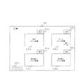
本発明に係る映像監視システムの一実施形態は、図1に示すように被監視サイトである複数の駅舎サイト1〜nと、これらの複数の駅舎サイト1〜nと通信回線として例えばインターネット網14を介して接続され、各駅舎サイト1〜nを遠隔的に監視する監視サイト7と、これらの複数の駅舎サイト1〜n及び監視サイト7とインターネット網14を介して接続され、各駅舎サイト1〜n及び監視サイト7と各種の情報を送受信して管理するデータセンタ10とを備えている。
As shown in FIG. 1, an embodiment of the video monitoring system according to the present invention includes a plurality of
各駅舎サイト1〜nは、例えば対応する駅舎のホーム、改札口(図3参照)、及び券売機(図3参照)等の状況を撮影する複数の監視カメラ2a〜2nを有している。以下、説明を分かり易くするために、便宜的にホームの状況を撮影する監視カメラに2a、改札口の状況を撮影する監視カメラに2b、券売機1の状況を撮影する監視カメラに2c、券売機1と異なる他の券売機2の状況を撮影する監視カメラに2dの符号を付し、その他の監視カメラ2e〜2nの記載を省略している。
Each
また、各駅舎サイト1〜nは、複数の監視カメラ2a〜2dによって撮影された映像を映像データとして記録する記録装置3と、この記録装置3に記録された映像データ(監視カメラ2a〜2dによって撮影された現在(リアルタイム)の映像の映像データを含む)を記録装置3から取出すカメラサーバ4と、このカメラサーバ4によって取出された映像データをインターネット網14を介して監視サイト7へ送信したり、監視サイト7から指令を受信するためにインターネット網14との通信の接続を行う通信装置5とを有している。
Further, each
また、各駅舎サイト1〜nは、例えば列車Aやホームで異常が発生したときに、その旨を知らせる非常ボタン(図示せず)と、この非常ボタンが押下されて送信された異常発生信号や券売機の故障信号等をイベント信号として検出するセンサ6とを有している。各駅舎サイト1〜nのカメラサーバ4は、センサ6によって検出されたイベント信号を通信装置5及びインターネット網14を介して監視サイト7及びデータセンタ10へ送信するようにしている。
Each
さらに、各駅舎サイト1〜nのカメラサーバ4は、記録装置3を介して取得した監視カメラ2a〜2dの現在の映像データを、通信装置5及びインターネット網14を介して監視サイト7へ送信すると共に、監視サイト7の指令を受け、記録装置3に記録された過去の映像データを取り出し、通信装置5及びインターネット網14を介して監視サイト7へ送信するようにしている。
Furthermore, the camera server 4 of each
データセンタ10は、例えばインターネット網14との通信の接続を行う通信装置13と、内部の各機器を制御すると共に、駅舎サイト1〜nのカメラサーバ4がセンサ6から出力されたイベント信号を受信した際に、このイベント信号に対して各種の情報を関連付けるCPU11と、イベント信号に付帯される各種の情報を少なくとも記憶するデータベース12とを有している。このデータベース12に記憶される各種の情報には、例えばイベント信号の送信元の駅舎名、イベント信号が送信された日時情報、及び当該駅舎の監視カメラ2a〜2dの識別番号等が含まれている。
The
一方、監視サイト7は、内部の各機器を制御する制御装置15を備え、この制御装置15は、例えばインターネット網14及び通信装置5を介して各駅舎サイト1〜nのカメラサーバ4との通信を行い、記録装置3に記録された映像データの取込みの指令を遠隔的に行うようにしている。
On the other hand, the monitoring site 7 includes a control device 15 that controls each internal device, and this control device 15 communicates with the camera servers 4 of each
また、監視サイト7は、各駅舎サイト1〜nのホームへ入線してから出発するまでの列車Aの位置情報に基づいて、列車Aがホームへ入線した駅舎サイトを特定する駅舎特定装置を備え、この駅舎特定装置は、例えば前述の制御装置15と、各駅舎サイト1〜nを運行する列車Aがホームへ入線する時刻及び出発する時刻を記憶し、これらの列車Aがホームへ入線する時刻及び出発する時刻から識別された列車Aの入線や出発等の位置情報を含む列車運行情報を制御装置15へ送信する列車運行状況識別装置18とから成っている。
Moreover, the monitoring site 7 is provided with a station building specifying device for specifying a station building site where the train A has entered the home based on the position information of the train A from the time when the train A enters the platform of each
さらに、監視サイト7は、各駅舎サイト1〜nの監視カメラ2a〜2dのうち駅舎特定装置によって特定された駅舎サイトのホームを撮影する監視カメラ2aの映像を表示する表示装置8と、インターネット網14との通信の接続を行う通信装置9と、監視サイト7の動作等のプログラムを格納する記憶部17とを備えている。
Furthermore, the monitoring site 7 includes a
また、制御装置15は、例えば列車運行状況識別装置18から受信した列車運行情報に含まれる列車Aの位置情報に基づいて、列車Aがホームへ入線した駅舎サイトを特定するようにしている。そして、監視サイト7は、制御装置15によって列車Aがホームへ入線した駅舎サイトが特定されたとき、この特定された駅舎サイトのホームを撮影する監視カメラ2aの現在の映像、及び駅舎サイト1〜nの記録装置3に記録された映像のうち現在の時刻よりも所定時間前の当該監視カメラ2aの過去の映像を、表示装置8の同一画面に入線監視用同時表示画面8A(図2参照)として表示させる画面表示指令装置16とを備えている。
Moreover, the control apparatus 15 is made to identify the station building site where the train A entered the home based on the position information of the train A included in the train operation information received from the train operation
この画面表示指令装置16は、制御装置15によって列車Aがホームへ入線した駅舎サイトが特定されていないとき、複数の監視カメラ2a〜2dの現在の映像のうち少なくとも1つを通常監視用画面8B(図3参照)として表示させ、この通常監視用画面8Bに表示された映像を複数の監視カメラ2a〜2dの現在の映像のうち通常監視用画面8Bに表示されていない映像に所定時間毎に切替えるようにしている。
When the station building site where the train A enters the home is not specified by the control device 15, the screen
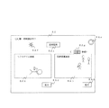
上述した表示装置8に表示される入線監視用同時表示画面8Aは、例えば図2に示すように予め設定した駅舎サイト1〜nのホームを撮影する監視カメラ2aの映像データを表示する表示エリアを含んでおり、これらの表示エリアは、例えば左右2つに配置されており、左側の表示エリアは、制御装置15によって特定された駅舎サイトのホームを撮影する監視カメラ2aの現在の映像が表示されるカメラ映像表示部8Aaから成り、右側の表示エリアは、記録装置3に記録された映像のうち現在の時刻よりも所定時間、例えば1分前の当該監視カメラ2aの過去の映像が表示される映像記録データ表示部8Abから成っている。従って、この入線監視用同時表示画面8Aの右側の映像記録データ表示部8Abには、左側のカメラ映像表示部8Aaに映し出された映像に対して1分遡った映像が表示されるようになっている。
The incoming line monitoring
また、入線監視用同時表示画面8Aは、例えば表示装置8の画面を入線監視用同時表示画面8Aから通常監視用画面8Bに切替える通常監視切替ボタン8Acと、カメラ映像表示部8Aa及び映像記録データ表示部8Abに映し出された映像を拡大して1画面表示に切替える拡大ボタン8Adとを含んでいる。さらに、入線監視用同時表示画面8Aは、例えば制御装置15によって特定された駅舎サイトのホームへ入線した列車Aの車掌室(図示せず)、当該駅舎サイトの駅員室(図示せず)、及び当該駅舎サイトを管理し、他の駅舎サイトに設置された駅員室(図示せず)のうち少なくとも1つへ報知する報知部を含んでいる。なお、各駅舎サイト1〜nの駅員室が例えば無人駅である場合には、当該駅舎サイトを他の駅舎サイトの駅員室が管理するようになっている。
The incoming line monitoring
本実施形態では、報知部は、制御装置15によって特定された駅舎サイトのホームへ入線した列車Aの車掌室(図示せず)、当該駅舎サイトの駅員室(図示せず)、及び当該駅舎サイトを管理し、他の駅舎サイトに設置された駅員室(図示せず)のうち、例えば制御装置15によって特定された駅舎サイトの駅員室内にアナウンスで報知する報知ボタン8Aeから成っている。そして、入線監視用同時表示画面8Aは、例えばこの報知ボタン8Aeによって報知中であることを、表示装置8の画面において点滅させて表示するランプ8Afを含んでいる。
In the present embodiment, the notification unit includes a conductor's room (not shown) of the train A that has entered the platform of the station building site identified by the control device 15, a station staff room (not shown) of the station building site, and the station building site. Among the station staff rooms (not shown) installed at other station building sites, for example, the notification button 8Ae is used to notify the station staff room of the station building site specified by the control device 15 by an announcement. The incoming line monitoring
さらに、入線監視用同時表示画面8Aは、右側の映像記録データ表示部8Abに表示される映像の頭出しとして指定される時刻、すなわち現在の時刻よりも所定時間前の時刻を設定する時間情報入力エリア8Agを含んでおり、この時間情報入力エリア8Agの設定が変更されることで映像記録データ表示部8Abに再生される記録装置3の映像データの指定時刻が調整されるようになっている。なお、本実施形態では、時間情報入力エリア8Agによって1分(60秒)前が設定されているので、60秒前が入線監視用同時表示画面8A上に表示されている。
Further, the incoming line monitoring
一方、通常監視用画面8Bは、例えば図3に示すように駅舎サイト1〜nに設置された複数の監視カメラ2a〜2dの映像を、駅舎サイト1〜n毎に表示する表示エリア(以下、便宜的にカメラ映像表示部8Ba,8Bb,8Bc,8Bdと表記する)を含んでおり、これらのカメラ映像表示部8Ba〜8Bdは、例えば左右上下に配置されている。
On the other hand, the normal monitoring screen 8B, for example, as shown in FIG. 3, is a display area (hereinafter referred to as “display area”) that displays images of the plurality of monitoring cameras 2a to 2d installed at the
そして、右上側のカメラ映像表示部8Bbに監視カメラ2aで撮影されたホーム全体の現在の映像が表示されると共に、左上側のカメラ映像表示部8Baに監視カメラ2bで撮影された改札口の現在の映像が表示されるようになっている。また、左下側のカメラ映像表示部8Bcに監視カメラ2cで撮影された券売機1の現在の映像が表示されると共に、右下側のカメラ映像表示部8Bdに監視カメラ2dで撮影された券売機2の現在の映像が表示されるようになっている。
Then, the current video of the entire home photographed by the surveillance camera 2a is displayed on the camera video display unit 8Bb on the upper right side, and the current ticket gate taken by the surveillance camera 2b on the camera video display unit 8Ba on the upper left side. Video is displayed. In addition, the current video of the
また、通常監視用画面8Bは、カメラ映像表示部8Ba〜8Bdの右上にそれぞれ設けられ、各カメラ映像表示部8Ba〜8Bdに表示された映像を拡大して1画面表示に切替える拡大ボタン8Beと、通常監視用画面8Bからログアウトし、表示装置8に表示される映像による監視業務を終了させるログアウトボタン8Bfとを含んでいる。なお、通常監視用画面8Bのカメラ映像表示部8Ba〜8Bdに表示される駅舎サイト1〜nの映像は、例えば画面表示指令装置16の指令である所定時間毎(例えば1分毎)に表示対象とする駅舎サイト1〜nを順次切替えて表示されるようになっている。すなわち、通常監視時の画面表示指令装置16は、各駅舎サイト1〜nに設けられる監視カメラ2a〜2dが撮影する現在の映像を、各駅舎サイト1〜n毎に所定時間(例えば1分)間隔でカメラ映像表示部8Ba〜8Bdへ表示させるものである。
Further, the normal monitoring screen 8B is provided at the upper right of the camera image display units 8Ba to 8Bd, and an enlarge button 8Be for enlarging the images displayed on the camera image display units 8Ba to 8Bd and switching to one screen display, A logout button 8Bf for logging out from the normal monitoring screen 8B and ending the monitoring work by the video displayed on the
次に、本実施形態の動作を図4のフローチャートに基づいて詳細に説明する。 Next, the operation of this embodiment will be described in detail based on the flowchart of FIG.
図4は本実施形態の動作を説明するフローチャートである。 FIG. 4 is a flowchart for explaining the operation of this embodiment.
本実施形態は、監視サイト7の制御装置15は、列車運行状況識別装置18から列車運行情報を受信すると、この列車運行情報に含まれる列車Aの位置情報を参照し、現在の時刻が列車Aが駅舎サイト1〜nのホームへ入線する時刻であるかどうかを判断する(ステップ(以下、Sと記す)1)。
In the present embodiment, when the control device 15 of the monitoring site 7 receives the train operation information from the train operation
このとき、制御装置15は、現在の時刻が列車Aが駅舎サイト1〜nのホームへ入線する時刻でないと判断すると、表示装置8は、画面表示指令装置16の指令により、通常監視用画面8Bの表示を継続し(S2)、通常監視用画面8Bにおいて所定時間として設定された1分毎に駅舎サイト1〜nの監視カメラ2a〜2dの現在の映像を順次切替えて表示する(S3)。
At this time, if the control device 15 determines that the current time is not the time at which the train A enters the platform of the
監視員は、通常監視用画面8Bによる駅舎サイト1〜nの監視業務を継続し、例えば図3に示すようにカメラ映像表示部8Bbに表示された駅舎サイト1のホームに乗客が倒れているのを確認すると、カメラ映像表示部8Bbの右上にある拡大ボタン8Beを操作してカメラ映像表示部8Bbの映像を拡大して1画面表示に切替え、ホームの状況の詳細を確認する等の監視業務を行う。
The monitoring staff continues the monitoring work of the
手順S1において制御装置15は、現在の時刻が列車Aが駅舎サイト1〜nのホームへ入線する時刻であると判断すると、駅舎サイト1〜nのうち入線監視用同時表示画面8Aに表示すべき駅舎サイトを特定し(S4)、特定した駅舎サイトの駅舎特定情報と表示装置8の画面を切替える旨の画面切替指令信号を画面表示指令装置16へ送信すると共に、特定した駅舎サイトのカメラサーバ4に対し、記録装置3に記録された映像のうち現在の時刻よりも1分前の監視カメラ2aの過去の映像を記録映像データとして送信させる(S5)。
When the control device 15 determines in step S1 that the current time is the time when the train A enters the platform of the
画面表示指令装置16は、制御装置15から画面切替指令信号を受信すると、表示装置8の画面を通常監視用画面8Bから入線監視用同時表示画面8Aへ切替える(S6)。一方、監視サイト7の通信装置9がインターネット網14を介してカメラサーバ4から記録映像データを受信すると(S7)、画面表示指令装置16は、手順S4において制御装置15によって特定された駅舎サイトのホームを撮影する監視カメラ2aの現在の映像を入線監視用同時表示画面8Aのカメラ映像表示部8Aaに表示させると共に、受信した記録映像データを再生して当該駅舎サイトの記録装置3に記録された映像のうち現在の時刻よりも1分前の監視カメラ2aの過去の映像を入線監視用同時表示画面8Aの映像記録データ表示部8Abに表示させる(S8)。
When receiving the screen switching command signal from the control device 15, the screen
次に、監視員は、表示装置8に表示された入線監視用同時表示画面8Aを監視し、例えば図2に示すように乗客がホームで倒れているのをカメラ映像表示部8Aaから確認すると、報知ボタン8Aeを操作して手順S4において制御装置15によって特定された駅舎サイトの駅員室へアナウンスで報知し、映像記録データ表示部8Abを確認する。このとき、映像記録データ表示部8Abには現在、ホームで倒れている乗客と他の2名の乗客が映し出されており、乗客がホームで倒れた経緯を容易に把握して検証することができる。
Next, the supervisor monitors the
次に、制御装置15は、入線監視用同時表示画面8Aの通常監視切替ボタン8Acが操作されたかどうかを判断する(S9)。手順S9において制御装置15は、入線監視用同時表示画面8Aの通常監視切替ボタン8Acが操作されていないと判断すると、列車運行状況識別装置18から受信した列車運行情報に含まれる列車Aの位置情報を参照し、現在の時刻が手順S4において制御装置15によって特定された駅舎サイトのホームから列車Aが出発した時刻であるかどうかを判断する(S10)。
Next, the control device 15 determines whether or not the normal monitoring switching button 8Ac on the incoming line monitoring
このとき、制御装置15は、現在の時刻が手順S4において制御装置15によって特定された駅舎サイトのホームから列車Aが出発した時刻でないと判断すると、手順S9の動作に戻る。一方、手順S9において制御装置15は、入線監視用同時表示画面8Aの通常監視切替ボタン8Acが操作されていると判断し、あるいは手順S10において制御装置15は、現在の時刻が手順S4において制御装置15によって特定された駅舎サイトのホームから列車Aが出発した時刻であると判断すると、手順S2からの動作が繰り返される。
At this time, if the control device 15 determines that the current time is not the time at which the train A departs from the home of the station building site specified by the control device 15 in step S4, the control device 15 returns to the operation of step S9. On the other hand, in step S9, the control device 15 determines that the normal monitoring switching button 8Ac on the incoming line monitoring
このように構成した本実施形態によれば、制御装置15によって列車Aが駅舎サイト1〜nのうち入線監視用同時表示画面8Aに表示すべき駅舎サイトが特定されたとき、すなわち列車Aが駅舎サイト1〜nのうちいずれかのホームへ入線したときには、画面表示指令装置16が表示装置8の画面を通常監視用画面8Bから入線監視用同時表示画面8Aへ切替えることにより、監視サイト7の監視員に列車Aが特定された駅舎サイトのホームへ入線したことを知らせると共に、列車Aのホームへの入線時におけるホームの状況を表示装置8の画面上から集中的に監視することを促すことができる。
According to the present embodiment configured as described above, when the control device 15 specifies a station building site that the train A should display on the incoming line monitoring
そして、監視員は表示画面8に映し出された入線監視用同時表示画面8Aのカメラ映像表示部8Aa及び映像記録データ表示部8Abを確認することにより、制御装置15によって特定された駅舎サイトのホームの現在の状況と1分前の過去の状況を同一画面上から容易に分析できるので、現在のホームの状況に至るまでの経緯を的確に把握することができる。これにより、監視員は、報知ボタン8Aeを操作することにより、制御装置15によって特定された駅舎サイトの駅員室へアナウンスで報知して適切な指示を行うことができる。このように、列車Aの接近に伴うホームにおける乗客の安全確認を確実に行うと共に、ホームの状況変化を迅速に把握することができる。
Then, the supervisor checks the camera video display unit 8Aa and the video recording data display unit 8Ab of the
また、本実施形態は、制御装置15によって駅舎サイト1〜nのうち入線監視用同時表示画面8Aに表示すべき駅舎サイトが特定されていないとき、すなわち列車Aが駅舎サイト1〜nのホームへ入線していないときには、画面表示指令装置16によって表示装置8の通常監視用画面8Abに各駅舎サイト1〜nの監視カメラ2a〜2dの映像が1分毎に順次切替えて表示されるので、監視員は、列車Aがホームへ入線していない状態におけるホーム、改札口、券売機1、及び券売機2の様子を効率良く監視することができる。これにより、監視員の監視業務にかかる負担を軽減することができる。
Further, in the present embodiment, when the station building site to be displayed on the incoming line monitoring
なお、上述した本実施形態は、本発明を分かり易く説明するために詳細に説明したものであり、必ずしも説明した全ての構成を備えるものに限定されるものではない。また、ある実施形態の構成の一部を他の実施形態の構成に置き換えることが可能であり、また、ある実施形態の構成に他の実施形態の構成を加えることも可能である。 In addition, this embodiment mentioned above was described in detail in order to demonstrate this invention easily, and is not necessarily limited to what is provided with all the demonstrated structures. Further, a part of the configuration of an embodiment can be replaced with the configuration of another embodiment, and the configuration of another embodiment can be added to the configuration of an embodiment.
また、本実施形態は、列車運行状況識別装置18は、各駅舎サイト1〜nを運行する列車Aが入線する時刻及び出発する時刻を記憶し、これらの列車Aが入線する時刻及び出発する時刻から識別された列車Aの入線や出発等の位置情報を含む列車運行情報を制御装置15へ送信するようにした場合について説明したが、列車Aの入線や出発等の位置情報は、例えば各駅舎サイト1〜nのホームの近傍に設けられ、列車Aが入線したことを検出する列車検出装置(図示せず)による検出信号から取得しても良い。
In the present embodiment, the train operation
1〜n 駅舎サイト
2a〜2n 監視カメラ
3 記録装置
4 カメラサーバ
5,9,13 通信装置
7 監視サイト
8 表示装置
8A 入線監視用同時表示画面
8Aa,8Ba〜8Bd カメラ映像表示部
8Ab 映像記録データ表示部
8Ac 通常監視切替ボタン
8Ad,8Be 拡大ボタン
8Ae 報知ボタン
8Af ランプ
8Ag 時間情報入力エリア
8B 通常監視用画面
8Bf ログアウトボタン
10 データセンタ
11 CPU
12 DB(データベース)
14 インターネット網
15 制御装置
16 画面表示指令装置
17 記憶部
18 列車運行状況識別装置
1-n Station building site 2a-
12 DB (database)
14 Internet network 15
Claims (2)
前記駅舎特定装置によって前記列車がホームへ入線した前記駅舎が特定されたとき、この特定された駅舎のホームを撮影する前記監視カメラの現在の映像、及び前記記録装置に記録された映像のうち現在の時刻よりも所定時間前の当該監視カメラの過去の映像を、前記表示装置の同一画面に入線監視用同時表示画面として表示させる画面表示指令装置を備えたことを特徴とする映像監視システム。 A plurality of surveillance cameras that photograph the homes of a plurality of station buildings that are monitored sites, a recording device that records images captured by the plurality of surveillance cameras, and remotely via the monitored site and a communication line A monitoring site to be connected, and this monitoring site, based on the position information of the train from entering the home until it departs, a station building identifying device that identifies the station building where the train entered the home, In a video surveillance system having a display device for displaying a video of a surveillance camera that photographs the platform home identified by the station building identification device among the plurality of surveillance cameras,
When the station building where the train enters the platform is identified by the station building identifying device, the current video of the monitoring camera that captures the platform home of the identified station and the video recorded in the recording device A video monitoring system comprising: a screen display commanding device for displaying a past video of the monitoring camera a predetermined time before the time as a simultaneous display screen for incoming line monitoring on the same screen of the display device.
前記画面表示指令装置は、前記駅舎特定装置によって前記列車がホームへ入線した前記駅舎が特定されていないとき、前記複数の監視カメラの現在の映像のうち少なくとも1つを通常監視用画面として表示させ、この通常監視用画面に表示された映像を前記複数の監視カメラの現在の映像のうち前記通常監視用画面に表示されていない映像に所定時間毎に切替えることを特徴とする映像監視システム。 The video surveillance system according to claim 1,
The screen display command device displays at least one of the current images of the plurality of monitoring cameras as a normal monitoring screen when the station building where the train enters the home is not specified by the station building specifying device. A video monitoring system, wherein the video displayed on the normal monitoring screen is switched to a video not displayed on the normal monitoring screen among the current videos of the plurality of monitoring cameras at predetermined time intervals.
Priority Applications (1)
| Application Number | Priority Date | Filing Date | Title |
|---|---|---|---|
| JP2013161310A JP2015032995A (en) | 2013-08-02 | 2013-08-02 | Video monitoring system |
Applications Claiming Priority (1)
| Application Number | Priority Date | Filing Date | Title |
|---|---|---|---|
| JP2013161310A JP2015032995A (en) | 2013-08-02 | 2013-08-02 | Video monitoring system |
Publications (1)
| Publication Number | Publication Date |
|---|---|
| JP2015032995A true JP2015032995A (en) | 2015-02-16 |
Family
ID=52517975
Family Applications (1)
| Application Number | Title | Priority Date | Filing Date |
|---|---|---|---|
| JP2013161310A Pending JP2015032995A (en) | 2013-08-02 | 2013-08-02 | Video monitoring system |
Country Status (1)
| Country | Link |
|---|---|
| JP (1) | JP2015032995A (en) |
Cited By (2)
| Publication number | Priority date | Publication date | Assignee | Title |
|---|---|---|---|---|
| CN108234568A (en) * | 2016-12-21 | 2018-06-29 | 比亚迪股份有限公司 | Medical service method, server-side and system based on rail traffic |
| CN112640444A (en) * | 2018-08-20 | 2021-04-09 | 株式会社音乐馆 | Station monitoring device, station monitoring method, and program |
-
2013
- 2013-08-02 JP JP2013161310A patent/JP2015032995A/en active Pending
Cited By (2)
| Publication number | Priority date | Publication date | Assignee | Title |
|---|---|---|---|---|
| CN108234568A (en) * | 2016-12-21 | 2018-06-29 | 比亚迪股份有限公司 | Medical service method, server-side and system based on rail traffic |
| CN112640444A (en) * | 2018-08-20 | 2021-04-09 | 株式会社音乐馆 | Station monitoring device, station monitoring method, and program |
Similar Documents
| Publication | Publication Date | Title |
|---|---|---|
| JP6845307B2 (en) | Monitoring system and monitoring method | |
| CN102368345B (en) | Elevator remote monitoring system | |
| US9449482B2 (en) | Method and apparatus for activating and deactivating video cameras in a security system | |
| JP6391540B2 (en) | Elevator inspection support system | |
| TWI411978B (en) | System and method for elevator security | |
| CN112520528B (en) | Automatic monitoring elevator fault detection system and detection method thereof | |
| JP2013089076A (en) | Support system of fire alarm facility | |
| JP2007241631A (en) | Building monitoring system | |
| JP5789230B2 (en) | Video surveillance system | |
| CN111891870B (en) | Visual alarm rescue system | |
| JP2015016704A (en) | Video monitoring system for station | |
| JP2015032995A (en) | Video monitoring system | |
| JP2009298495A (en) | Information distribution system of elevator | |
| JP2006285639A (en) | Presence operation support system and presence operation support vehicles | |
| CN110928305B (en) | Patrol method and system for patrol robot of railway passenger station | |
| JP2017215694A (en) | Control system, monitoring device, monitoring program, monitoring method and image sensor | |
| KR101758008B1 (en) | System for real time monitoring video of subway in relation to fire detection | |
| KR101694072B1 (en) | System for controlling video error in monitoring subway passenger's situation | |
| JP5484224B2 (en) | Device for detecting string-like foreign matter on doors of railway vehicles | |
| JPH09182061A (en) | Safety monitoring method by image | |
| JP2017041013A (en) | Remote monitoring device for inside of tunnel | |
| KR101874639B1 (en) | CCTV camera device for elevators using motion sensor | |
| JP5824332B2 (en) | Monitoring device | |
| JP2010205191A (en) | Safety management device | |
| JP2001006071A (en) | Remote monitoring device for elevator |