JP2015031663A - Rotation detecting device and manufacturing method thereof - Google Patents
Rotation detecting device and manufacturing method thereof Download PDFInfo
- Publication number
- JP2015031663A JP2015031663A JP2013163510A JP2013163510A JP2015031663A JP 2015031663 A JP2015031663 A JP 2015031663A JP 2013163510 A JP2013163510 A JP 2013163510A JP 2013163510 A JP2013163510 A JP 2013163510A JP 2015031663 A JP2015031663 A JP 2015031663A
- Authority
- JP
- Japan
- Prior art keywords
- wire
- stay
- hole
- holes
- rotation
- Prior art date
- Legal status (The legal status is an assumption and is not a legal conclusion. Google has not performed a legal analysis and makes no representation as to the accuracy of the status listed.)
- Granted
Links
Images
Classifications
-
- G—PHYSICS
- G01—MEASURING; TESTING
- G01P—MEASURING LINEAR OR ANGULAR SPEED, ACCELERATION, DECELERATION, OR SHOCK; INDICATING PRESENCE, ABSENCE, OR DIRECTION, OF MOVEMENT
- G01P1/00—Details of instruments
- G01P1/006—Details of instruments used for thermal compensation
Landscapes
- Physics & Mathematics (AREA)
- General Physics & Mathematics (AREA)
- Transmission And Conversion Of Sensor Element Output (AREA)
Abstract
Description
本発明は、回転検出装置およびその製造方法に関し、特に、コスト低減技術に関する。 The present invention relates to a rotation detection device and a manufacturing method thereof, and more particularly to a cost reduction technique.
車輪の回転を検出する車輪速センサなどの回転検出装置が知られている。たとえば特許文献1に開示されているように、回転検出装置は、樹脂製のステーにより、ワイヤと回転検出部を保持するハウジングとが一体的に保持されている。
2. Description of the Related Art A rotation detection device such as a wheel speed sensor that detects wheel rotation is known. For example, as disclosed in
ワイヤは信号線を樹脂製の被覆層により被覆している構造であり、ステー成形時にはワイヤの被覆層がステーの材料である溶融樹脂からの熱により高温になる。そのため、架橋樹脂などの耐熱性被覆層が用いられている高価なワイヤを使用する必要があった。その結果、回転検出装置が高価なものになってしまっていた。 The wire has a structure in which the signal line is covered with a resin coating layer, and at the time of stay molding, the wire coating layer becomes high temperature due to heat from the molten resin that is a material of the stay. Therefore, it is necessary to use an expensive wire in which a heat-resistant coating layer such as a crosslinked resin is used. As a result, the rotation detection device has become expensive.
本発明は、この事情に基づいて成されたものであり、その目的とするところは、耐熱性の低い樹脂をワイヤの被覆層として使用することができる回転検出装置およびその製造方法を提供することにある。 The present invention has been made based on this situation, and an object of the present invention is to provide a rotation detecting device capable of using a resin having low heat resistance as a coating layer of a wire, and a method for manufacturing the same. It is in.
その目的を達成するための装置発明は、信号線(11)が樹脂製の被覆層(13)で覆われたワイヤ(10)と、そのワイヤと接続されており、検出対象の回転を検出して回転に応じた電気信号を出力する回転検出部(40)と、回転検出部を保持するハウジング(20)と、ハウジングとワイヤとを一体に保持する樹脂製のステー(30)とを備えた回転検出装置(1)であって、ステーに穴が形成されていることを特徴とする。 In the device invention for achieving the object, the signal line (11) is connected to the wire (10) covered with the resin coating layer (13) and the wire, and detects the rotation of the detection target. A rotation detector (40) that outputs an electrical signal according to rotation, a housing (20) that holds the rotation detector, and a resin stay (30) that holds the housing and the wire together. The rotation detecting device (1) is characterized in that a hole is formed in the stay.
本発明によれば、樹脂製のステーに穴が形成されている。樹脂製のステーに穴を形成しようとすると、ステーの成形工程において、穴に対応する部分を一部に含むピンを金型内に配置することになる。このピンをステーよりも熱伝導率の高い材質(たとえば金属製)とすれば、溶融樹脂の熱を放熱させることができるので、被覆層の温度上昇を抑制できる。これにより、被覆層に要求される耐熱温度が低くなるので、耐熱性の低い樹脂が被覆層に使用されている安価なワイヤを使用することが可能になる。 According to the present invention, the hole is formed in the resin stay. If a hole is to be formed in a resin stay, a pin partially including a portion corresponding to the hole is disposed in the mold in the stay molding step. If this pin is made of a material having a higher thermal conductivity than the stay (for example, metal), the heat of the molten resin can be dissipated, so that the temperature rise of the coating layer can be suppressed. Thereby, since the heat resistant temperature required for the coating layer is lowered, it becomes possible to use an inexpensive wire in which a resin having low heat resistance is used for the coating layer.
また、前述の目的を達成するための製造方法の発明は、上記装置発明にかかる回転検出装置の製造方法であって、ハウジングに保持された回転検出部とワイヤとが電気的に接合され、所定の金型に収容された状態で、穴に対応する部分を一部に含み、ステーよりも熱伝導率の高い材質の放熱ピンを金型内に配置する配置工程(S3)と、その放熱ピン配置工程の後、ステーの材料となる溶融樹脂を金型内に注入することでステーを成形するステー成形工程(S4)とを含むことを特徴とする。 An invention of a manufacturing method for achieving the above-described object is a method of manufacturing a rotation detecting device according to the above device invention, wherein a rotation detecting unit and a wire held in a housing are electrically joined, and A disposing step (S3) in which a heat dissipating pin made of a material having a part of the hole corresponding to the hole and having a higher thermal conductivity than the stay is disposed in the metal mold, and the heat dissipating pin. And a stay molding step (S4) for molding the stay by injecting molten resin as a material for the stay into the mold after the arranging step.
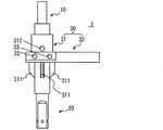
以下、本発明の実施形態を図面に基づいて説明する。図1に外観図を示す車輪速センサ1は、この外観図から分かるように、ワイヤ10、ハウジング20、ステー30を備える。
Hereinafter, embodiments of the present invention will be described with reference to the drawings. The
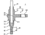
図2の断面図に示すように、ワイヤ10は、内部に金属製の信号線11を備えており、その信号線11の外周をシールド層12が覆っている。なお、図2には信号線11は1本しか示されていないが、ワイヤ10は信号線11を2本備えている。そして、シールド層12は、それら2本の信号線11をまとめて覆っている。シールド層12のさらに外周は樹脂製の被覆層13が覆っている。この被覆層13は、たとえば、非架橋のポリウレタン樹脂製(すなわち非架橋樹脂製)である。
As shown in the cross-sectional view of FIG. 2, the
ワイヤ10の先端部分では、信号線11は、被覆層13およびシールド層12から露出している。被覆層13の先端部分および被覆層13の先端部分から露出しているシールド層12、信号線11はハウジング20に覆われている。
At the tip end portion of the
ハウジング20は、樹脂製であり、先端部に回転検出部40を収容し、かつ、その回転検出部40をハウジング20に対して移動不能に保持している。回転検出部40は、内部にセンサ素子や処理回路(いずれも不図示)を備える本体部41と、その本体部41から突き出すリードフレーム42とを備える。リードフレーム42の先端は、信号線11の先端と電気的に接続されている。
The
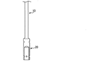
図3は、ハウジング20にワイヤ10の先端が収容された状態を示している。図3に示す状態は、リードフレーム42と信号線11の先端とを接合した後、それらを覆うようにハウジング20を成形することで得られる。その後、図3に示したものに対しステー30を成形する。これら接合、成形方法は後述する。
FIG. 3 shows a state in which the tip of the
図1、2に示すように、ステー30は、ワイヤ10およびハウジング20を一体に保持する保持部31と、所定の取付対象体(たとえば、車輪のハブなど)に固定される取付部32とを備えている。これら保持部31、取付部32は、射出成形により一体成形される。
As shown in FIGS. 1 and 2, the
保持部31は、ハウジング20のワイヤ10側端部とワイヤ10の先端部を覆っており、略円筒形状である。取付部32はこの保持部31の軸方向の中央付近から保持部31の径方向に突き出している。取付部32は、平板形状であり、先端側にカラー321が固定されている。このカラー321に図示しない固定用ボルトが貫通し、その固定用ボルトにより、車輪速センサ1は取付対象体に固定される。
The
保持部31には、取付部32が突き出している位置に隣接して、ハウジング20側に複数の端片311が径方向に突き出している。端片311は本実施形態では4つであり、保持部31の周方向に等間隔に配置されている。
A plurality of
保持部31には、さらに、取付部32を挟んで上記端片311と反対側に、取付部32に隣接して有底穴312が形成されている(図1参照)。有底穴312は図1では1つのみ示されているが、ワイヤ10を挟んで反対側にも、図1に示す有底穴312に対向する位置に、有底穴312が形成されている。つまり、本実施形態では有底穴312は2つ形成されている。これら2つの有底穴312は、保持部31をその保持部31の径方向に中心に向かって保持部31の内周面まで貫通している。保持部31は円筒形状であり、内側にワイヤ10を保持するものであることから、有底穴312の底面はワイヤ10の被覆層13の表面となる。なお、有底穴312の底面を、ワイヤ10の中心からワイヤ10の直径以上離れた位置としてもよい。
The
これら2つの有底穴312に加え、ステー30には、保持部31と取付部32とをともに貫通する(すなわちステー30を貫通する)一対の貫通穴33も形成されている。この貫通穴33は、有底穴312と同一方向に(すなわち平行に)形成されている。
In addition to these two bottomed
図2の断面図に示すように、一対の貫通穴33は、ワイヤ10に近接して形成されている。これは、ステー30の成形時に、この貫通穴33を形成するための放熱ピン51、51(図5参照)により、ワイヤ10の位置を図2の左右方向において規制するためである。よって、上記における近接とは、ワイヤ10と貫通穴33との距離が、成形時においてワイヤ10の移動が許容できる程度の距離であることを意味する。近接の程度を例示すると、ワイヤ10と貫通穴33との距離がワイヤ10の直径と同等またはそれ以下、より好ましくは、その距離がワイヤ10の半径以下である。ただし、放熱ピン51による放熱機能に着目した場合には貫通穴33の位置はワイヤ10に近接している必要はない。したがって、貫通穴33の位置は、図2の例に限定されず、放熱ピン51が設定可能な位置であればよい。
As shown in the sectional view of FIG. 2, the pair of through
有底穴312は、前述のように取付部32に隣接して形成されている。貫通穴33は、取付部32と保持部31とをともに貫通するように形成されている。つまり、有底穴312と貫通穴33は互いに近接している。
The bottomed
以上のように構成された車輪速センサ1は、取付対象体に取り付けられた状態では、車輪の回転に応じた電気信号を回転検出部40が出力する。この電気信号は、信号線11を介して、所定の信号処理部(図示せず)に入力される。
In the state where the
(車輪速センサ1の製造方法)
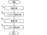
次に、以上の構成を有する車輪速センサ1の製造方法を図4を用いて説明する。ステップS1の接合工程では、リードフレーム42と信号線11の先端とを接合する。接合方法は公知の種々の方法を用いることができる。たとえば、抵抗溶接、超音波溶接等の公知の溶接方法や、ハンダ付けを用いることができる。
(Manufacturing method of wheel speed sensor 1)
Next, a manufacturing method of the
ステップS2のハウジング成形工程では、ハウジング20を成形する。ハウジングの成形方法も公知の種々の方法を用いることができる。たとえば、射出成形や圧縮成形などを用いることができる。射出成形を用いる場合、ハウジング20の材料となる樹脂(たとえばエポキシ樹脂)を注入するランナーを、たとえば、ハウジング20の中央付近に配置する。また、それよりも、さらにハウジング20の先端側に配置するようにしてもよい。反対に、ハウジング20の中央付近よりもワイヤ10側に配置してもよい。
In the housing molding process of step S2, the
ステップS3の配置工程では、ハウジング成形工程で成形した成形体を、ステー30を成形するための図示しない金型内に配置する。さらに、貫通穴33および有底穴312に対応する金型内の位置に、放熱ピン51、52を配置する。
In the arrangement process of step S3, the molded body molded in the housing molding process is arranged in a mold (not shown) for molding the
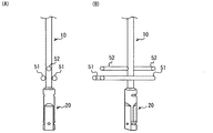
図5は放熱ピン51、52を配置した状態を示している。本実施形態では、貫通穴33および有底穴312を合わせて4つの穴がステー30に形成されている。従って、放熱ピン51、52は合計4本配置する。これら4本の放熱ピン51、52はいずれも、高い熱伝導率と高い耐熱性を備えた材料とするために金属製としている。
FIG. 5 shows a state in which the heat radiation pins 51 and 52 are arranged. In the present embodiment, four holes are formed in the
一対の放熱ピン51は貫通穴33を形成するためのものであり、図5(A)に示されるように、それら一対の放熱ピン51の側面でワイヤ10を挟むように、かつ、互いに平行に、それら一対の放熱ピン51は配置される。
The pair of radiating
これに対して、放熱ピン52は有底穴312を形成するためのものであり、図5(B)に示されるように、それら一対の放熱ピン52の先端面でワイヤ10を挟むように、かつ、ほぼ同一直線上に、それら一対の放熱ピン52は配置される。
On the other hand, the radiating
これら本実施形態の放熱ピン51、52は、端面が円形である。また、この図5から分かるように、4本の放熱ピン51、52は、互いにほぼ平行に配置されている。そして、側面でワイヤ10を挟んでいる一対の放熱ピン51により、ワイヤ10はその一対の放熱ピン51を含む平面において、放熱ピン51の径方向の移動が規制される。また、端面でワイヤ10を挟む一対の放熱ピン52により、ワイヤ10は、その一対の放熱ピン52の軸方向の移動が規制される。よって、4本の放熱ピン51、52が図5のように配置されることにより、ワイヤ10は、それら4本の放熱ピン51、52により挟まれている付近の移動は、ワイヤ10の径方向平面において、縦横両方向の移動が規制されることになる。
These heat radiation pins 51 and 52 of this embodiment have circular end faces. Further, as can be seen from FIG. 5, the four heat radiation pins 51 and 52 are arranged substantially parallel to each other. The pair of heat dissipation pins 51 sandwiching the
ステップS4のステー成形工程では、放熱ピン51、52によりワイヤ10の移動が規制された状態で、ステー30の材料となる樹脂(たとえばポリブチレンテレフタレート)を溶融状態で金型に注入する。溶融樹脂を注入するゲートは取付部32の先端部に対応する部分である。よって、溶融樹脂は、金型内に形成されたステー形状部分を、取付部32の先端から取付部32の基端へと流れ、そこから、保持部31の両端部へ向かって流れることになる。
In the stay molding process of step S4, a resin (for example, polybutylene terephthalate) as a material of the
溶融樹脂が冷却固化した後、金型から成形体を取り出し、取付部32にカラー321を取り付けることで、車輪速センサ1が製造できる。
After the molten resin is cooled and solidified, the
以上、説明した本実施形態によれば、樹脂製のステー30に2つの貫通穴33と、2つの有底穴312の合計4つの穴が形成されている。ステー30にこれら穴33、312を形成するために、配置工程(S3)において、穴33、312に対応する部分を一部に含む放熱ピン51、52を金型内に配置する。この放熱ピン51、52は金属製であり、樹脂製であるステー30よりも熱伝導率が高いので、ステー成形工程(S4)において、溶融樹脂の熱を放熱ピン51、52により素早く放熱させることができる。特に、貫通穴33を形成するための放熱ピン51は、貫通穴33の両側に延びることから放熱効果が高い。
As described above, according to the present embodiment described above, a total of four holes including the two through
これら4本の放熱ピン51、52があることにより、被覆層13の温度上昇が抑制できる。これにより、被覆層13に要求される耐熱温度が低くなるので、耐熱性の低い樹脂が被覆層13に使用されている安価なワイヤ10を使用することが可能になる。
By having these four heat radiation pins 51 and 52, the temperature rise of the
また、本実施形態では、貫通穴33、有底穴312は、いずれもステー30の保持部31において、取付部32が突き出している付近に形成されている。なお、ここでの付近には、保持部31において取付部32が突き出している部分も含む。また、取付部32が突き出している部分から保持部31の軸方向に離れる方向においては、たとえば、取付部32の厚さだけ離れるまでを付近とする。
In the present embodiment, the through
ステー30を成形するための溶融樹脂を注入するゲートは、取付部32の先端部に対応する部分である。したがって、保持部31に対応する部分においては、取付部32との結合部分が最もゲートに近い、すなわち、最も高温になる。本実施形態では、その部分の付近に、貫通穴33、有底穴312に対応する部分を一部に含む4本の放熱ピン51、52が配置されている。そのため、この放熱ピン51、52により溶融樹脂の熱が、特に素早く放熱される。
The gate for injecting molten resin for forming the
また、本実施形態では、一対の貫通穴33と一対の有底穴312がステー30に形成されている。そして、これらの穴33、312を形成するために、ステー成形工程(S4)では、一対の放熱ピン51、および、他の対の放熱ピン52は、いずれも、それら対となっている放熱ピンにより、ワイヤ10を挟むことになる。よって、ステー成形工程(S4)においてワイヤ10の位置を放熱ピン51、52により規制することもできる。
In the present embodiment, a pair of through
特に、一対の放熱ピン51と、他の対の放熱ピン52は、ワイヤ10の径方向平面において互いに直交する方向へのワイヤ10の移動を規制するように配置されている。そのため、ステー成形工程(S4)において、特に、ワイヤ10の位置を所望の位置としてステー30を成形することができる。
In particular, the pair of heat radiation pins 51 and the other pair of heat radiation pins 52 are arranged so as to restrict the movement of the
以上、本発明の実施形態を説明したが、本発明は上述の実施形態に限定されるものではなく、次の実施形態も本発明の技術的範囲に含まれ、さらに、下記以外にも要旨を逸脱しない範囲内で種々変更して実施することができる。 As mentioned above, although embodiment of this invention was described, this invention is not limited to the above-mentioned embodiment, The following embodiment is also contained in the technical scope of this invention, and also the summary other than the following is also included. Various modifications can be made without departing from the scope.
(変形例1)
たとえば、前述の実施形態では、放熱ピン51、52は、端面形状が円形であったが、楕円形や角形など、円形以外の端面形状でもよい。
(Modification 1)
For example, in the above-described embodiment, the heat radiation pins 51 and 52 have a circular end surface shape, but may have an end surface shape other than a circle such as an ellipse or a square.
(変形例2)
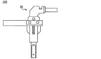
また、図6に示す車輪速センサ100のように、ステー30の基部がそれよりも先の部分に対して曲がった形状でもよい。
(Modification 2)
Moreover, the shape where the base part of the
(その他の変形例)
前述の実施形態では、2つの貫通穴33、および2つの有底穴312の合計4つの穴をステー30に形成していたが、貫通穴33、有底穴312のいずれか一種類のみを形成してもよい(変形例3)。また、1種類の穴とするか2種類の穴とするかによらず、穴の数は前述の実施形態に示した数に限られず、たとえば、穴が一つのみでもよい(変形例4)。よって、一対の貫通穴33、あるいは、一対の有底穴312を備えることも必須ではないことから、それらの穴33、312を形成するための放熱ピン51、52により、ステー成形工程(S4)においてワイヤ10の移動を規制していなくてもよい(変形例5)。また、穴33、312の位置も前述の実施形態の位置に限られず、保持部31において、取付部32が突き出している部分から離れた位置に穴33、312を形成してもよい(変形例6)。また、本発明は、車輪速センサ1、100に限られず、トランスミッションやエンジンに含まれている回転体など、種々の回転体の回転を検出する用途に仕様できる(変形例7)。
(Other variations)
In the above-described embodiment, a total of four holes including the two through
1 車輪速センサ(回転検出装置)、 10 ワイヤ、 11 信号線、 12 シールド層、 13 被覆層、 20 ハウジング、 30 ステー、 31 保持部、 32 取付部、 33 貫通穴、 40 回転検出部、 41 本体部、 42 リードフレーム、 51 放熱ピン、 52 放熱ピン、 311 端片、 312 有底穴、 321 カラー
DESCRIPTION OF
Claims (8)
そのワイヤと接続されており、検出対象の回転を検出して回転に応じた電気信号を出力する回転検出部(40)と、
前記回転検出部を保持するハウジング(20)と、
前記ハウジングと前記ワイヤとを一体に保持する樹脂製のステー(30)とを備えた回転検出装置(1)であって、
前記ステーに穴(33、312)が形成されていることを特徴とする回転検出装置。 A wire (10) in which the signal line (11) is covered with a resin coating layer (13);
A rotation detection unit (40) connected to the wire and detecting the rotation of the detection target and outputting an electrical signal corresponding to the rotation;
A housing (20) for holding the rotation detector;
A rotation detection device (1) comprising a resin stay (30) for integrally holding the housing and the wire,
A rotation detecting device, wherein holes (33, 312) are formed in the stay.
前記ワイヤの被覆層は非架橋樹脂製であることを特徴とする回転検出装置。 In claim 1,
The rotation detecting device, wherein the wire covering layer is made of non-crosslinked resin.
前記穴として、前記ステーを貫通する貫通穴(33)を備えることを特徴とする回転検出装置。 In claim 1 or 2,
A rotation detecting device comprising a through hole (33) penetrating the stay as the hole.
前記貫通穴が2つ形成され、それら2つの貫通穴はともに前記ワイヤに隣接しており、かつ、それら2つの貫通穴は前記ワイヤを挟んで互いに反対側に形成されていることを特徴とする回転検出装置。 In claim 3,
Two through holes are formed, both of the two through holes are adjacent to the wire, and the two through holes are formed on opposite sides of the wire. Rotation detection device.
前記穴として、底面が前記ワイヤの被覆層の表面となっている有底穴(312)を備えることを特徴とする回転検出装置。 In claim 1 or 2,
A rotation detecting device comprising a bottomed hole (312) having a bottom surface serving as a surface of the coating layer of the wire as the hole.
前記穴として、前記貫通穴に加えて、底面が前記ワイヤの被覆層の表面となっている有底穴(312)を2つ備え、
それら2つの有底穴は、前記ワイヤを挟んで互いに反対側に形成されており、かつ、前記貫通穴と同一方向に形成されていることを特徴とする回転検出装置。 In claim 4,
In addition to the through hole, the hole includes two bottomed holes (312) whose bottom surface is the surface of the coating layer of the wire,
These two bottomed holes are formed on opposite sides of the wire, and are formed in the same direction as the through hole.
前記ステーは、前記ワイヤと前記ハウジングとを保持する保持部(31)と、その保持部から保持部径方向に突き出しており、所定の取付対象体に固定される取付部(32)とを備え、
前記穴が、前記保持部において、前記取付部が突き出している付近に形成されていることを特徴とする回転検出装置。 In any one of Claims 1-6,
The stay includes a holding portion (31) that holds the wire and the housing, and an attachment portion (32) that protrudes from the holding portion in the radial direction of the holding portion and is fixed to a predetermined attachment object. ,
The rotation detecting device according to claim 1, wherein the hole is formed in the holding portion in the vicinity of the mounting portion protruding.
前記ハウジングに保持された前記回転検出部と前記ワイヤとが電気的に接合され、所定の金型に収容された状態で、前記穴に対応する部分を一部に含み、前記ステーよりも熱伝導率の高い材質の放熱ピン(51、52)を前記金型内に配置する配置工程(S3)と、
その配置工程の後、前記ステーの材料となる溶融樹脂を前記金型内に注入することで前記ステーを成形するステー成形工程(S4)とを含むことを特徴とする回転検出装置の製造方法。 It is a manufacturing method of a rotation detecting device given in any 1 paragraph of Claims 1-7,
The rotation detection unit held by the housing and the wire are electrically joined and accommodated in a predetermined mold, and a part corresponding to the hole is included in part and is more thermally conductive than the stay. A disposing step (S3) of disposing the heat dissipating pins (51, 52) of a high-rate material in the mold;
A method for manufacturing a rotation detecting device, comprising: a stay molding step (S4) for molding the stay by injecting molten resin as a material for the stay into the mold after the arranging step.
Priority Applications (2)
| Application Number | Priority Date | Filing Date | Title |
|---|---|---|---|
| JP2013163510A JP5971212B2 (en) | 2013-08-06 | 2013-08-06 | Rotation detecting device and manufacturing method thereof |
| US14/326,696 US20150040662A1 (en) | 2013-08-06 | 2014-07-09 | Apparatus for detecting rotational speed and method for manufacturing same |
Applications Claiming Priority (1)
| Application Number | Priority Date | Filing Date | Title |
|---|---|---|---|
| JP2013163510A JP5971212B2 (en) | 2013-08-06 | 2013-08-06 | Rotation detecting device and manufacturing method thereof |
Publications (2)
| Publication Number | Publication Date |
|---|---|
| JP2015031663A true JP2015031663A (en) | 2015-02-16 |
| JP5971212B2 JP5971212B2 (en) | 2016-08-17 |
Family
ID=52447434
Family Applications (1)
| Application Number | Title | Priority Date | Filing Date |
|---|---|---|---|
| JP2013163510A Active JP5971212B2 (en) | 2013-08-06 | 2013-08-06 | Rotation detecting device and manufacturing method thereof |
Country Status (2)
| Country | Link |
|---|---|
| US (1) | US20150040662A1 (en) |
| JP (1) | JP5971212B2 (en) |
Cited By (2)
| Publication number | Priority date | Publication date | Assignee | Title |
|---|---|---|---|---|
| JP2016017939A (en) * | 2014-07-11 | 2016-02-01 | 株式会社デンソー | Rotation detector |
| CN111596341A (en) * | 2020-06-28 | 2020-08-28 | 中国科学技术大学 | Manufacturing method of multi-air gap full resistive blind hole detector |
Families Citing this family (1)
| Publication number | Priority date | Publication date | Assignee | Title |
|---|---|---|---|---|
| US9970785B2 (en) * | 2014-12-08 | 2018-05-15 | Hitachi Metals, Ltd. | In-vehicle detection device |
Citations (11)
| Publication number | Priority date | Publication date | Assignee | Title |
|---|---|---|---|---|
| JPH0774193A (en) * | 1993-09-01 | 1995-03-17 | Sharp Corp | Method for sealing semiconductor device |
| JPH09133696A (en) * | 1995-11-10 | 1997-05-20 | Zexel Corp | Enclosed rotation sensor device and its manufacture |
| JP2000019185A (en) * | 1998-06-30 | 2000-01-21 | Denso Corp | Molding method of cable outlet and integrated cable structure |
| JP2001119847A (en) * | 1999-10-20 | 2001-04-27 | Hosiden Corp | Cable |
| JP2002137248A (en) * | 2000-11-06 | 2002-05-14 | Nagano Japan Radio Co | Manufacturing method of automobile parts and mold device |
| JP2004054753A (en) * | 2002-07-23 | 2004-02-19 | Sony Corp | Information processing apparatus and method, recording medium, and program |
| JP2005227156A (en) * | 2004-02-13 | 2005-08-25 | Honda Lock Mfg Co Ltd | Sensor device |
| JP2005529312A (en) * | 2002-03-27 | 2005-09-29 | シーメンス ヴイディオー オートモーティヴ | Method of manufacturing wheel speed sensor and corresponding sensor |
| US20100271015A1 (en) * | 2007-12-13 | 2010-10-28 | Continental Teves Ag & Co. Ohg | Magnetic field sensor element |
| JP2011219530A (en) * | 2010-04-05 | 2011-11-04 | Autonetworks Technologies Ltd | Composition for electrical wire covering material, insulated wire and wiring harness |
| JP2013104844A (en) * | 2011-11-16 | 2013-05-30 | Nidec Sankyo Corp | Magnetic sensor device |
Family Cites Families (4)
| Publication number | Priority date | Publication date | Assignee | Title |
|---|---|---|---|---|
| US5685884A (en) * | 1995-10-13 | 1997-11-11 | Bently Nevada Corporation | Method of making a transducer |
| US6643909B2 (en) * | 2001-04-10 | 2003-11-11 | Bently Nevada Llc | Method of making a proximity probe |
| JP4241267B2 (en) * | 2003-01-30 | 2009-03-18 | 株式会社デンソー | Rotation detector |
| JP2008209197A (en) * | 2007-02-26 | 2008-09-11 | Sumiden Electronics Kk | Rotation detection sensor |
-
2013
- 2013-08-06 JP JP2013163510A patent/JP5971212B2/en active Active
-
2014
- 2014-07-09 US US14/326,696 patent/US20150040662A1/en not_active Abandoned
Patent Citations (11)
| Publication number | Priority date | Publication date | Assignee | Title |
|---|---|---|---|---|
| JPH0774193A (en) * | 1993-09-01 | 1995-03-17 | Sharp Corp | Method for sealing semiconductor device |
| JPH09133696A (en) * | 1995-11-10 | 1997-05-20 | Zexel Corp | Enclosed rotation sensor device and its manufacture |
| JP2000019185A (en) * | 1998-06-30 | 2000-01-21 | Denso Corp | Molding method of cable outlet and integrated cable structure |
| JP2001119847A (en) * | 1999-10-20 | 2001-04-27 | Hosiden Corp | Cable |
| JP2002137248A (en) * | 2000-11-06 | 2002-05-14 | Nagano Japan Radio Co | Manufacturing method of automobile parts and mold device |
| JP2005529312A (en) * | 2002-03-27 | 2005-09-29 | シーメンス ヴイディオー オートモーティヴ | Method of manufacturing wheel speed sensor and corresponding sensor |
| JP2004054753A (en) * | 2002-07-23 | 2004-02-19 | Sony Corp | Information processing apparatus and method, recording medium, and program |
| JP2005227156A (en) * | 2004-02-13 | 2005-08-25 | Honda Lock Mfg Co Ltd | Sensor device |
| US20100271015A1 (en) * | 2007-12-13 | 2010-10-28 | Continental Teves Ag & Co. Ohg | Magnetic field sensor element |
| JP2011219530A (en) * | 2010-04-05 | 2011-11-04 | Autonetworks Technologies Ltd | Composition for electrical wire covering material, insulated wire and wiring harness |
| JP2013104844A (en) * | 2011-11-16 | 2013-05-30 | Nidec Sankyo Corp | Magnetic sensor device |
Cited By (3)
| Publication number | Priority date | Publication date | Assignee | Title |
|---|---|---|---|---|
| JP2016017939A (en) * | 2014-07-11 | 2016-02-01 | 株式会社デンソー | Rotation detector |
| US9523592B2 (en) | 2014-07-11 | 2016-12-20 | Denso Corporation | Rotation detector |
| CN111596341A (en) * | 2020-06-28 | 2020-08-28 | 中国科学技术大学 | Manufacturing method of multi-air gap full resistive blind hole detector |
Also Published As
| Publication number | Publication date |
|---|---|
| JP5971212B2 (en) | 2016-08-17 |
| US20150040662A1 (en) | 2015-02-12 |
Similar Documents
| Publication | Publication Date | Title |
|---|---|---|
| CN101688880B (en) | Rotation sensor | |
| CN103630703B (en) | Rotary sensing equipment and its manufacture method | |
| JP5971212B2 (en) | Rotation detecting device and manufacturing method thereof | |
| JP6303879B2 (en) | Manufacturing method of physical quantity measuring sensor, physical quantity measuring sensor, and manufacturing method of cable with resin molded body | |
| WO2010018661A1 (en) | Rotation sensor | |
| JPWO2018123879A1 (en) | Motor and electric power steering apparatus | |
| WO2013114943A1 (en) | Current detection device and magnetic core | |
| JP2010048689A (en) | Rotation detection sensor | |
| JP6111751B2 (en) | Electronic device and manufacturing method thereof | |
| EP3404384B1 (en) | Temperature detection device | |
| JP2009075053A (en) | Rotation detection sensor | |
| JP7083114B2 (en) | Temperature sensor module and its manufacturing method | |
| JP2008241557A (en) | Rotation detecting sensor | |
| JP2009075052A (en) | Rotation detection sensor | |
| JP6214260B2 (en) | Current detector | |
| JP2010043889A (en) | Rotation detection sensor | |
| JP5063231B2 (en) | Rotation detection sensor / fixing member mounting body | |
| JP2014071105A (en) | In-vehicle sensor | |
| JP2011133280A (en) | Moving-object detection device | |
| CN207456633U (en) | A kind of engine temperature sensing unit | |
| CN207819605U (en) | Motor and electromechanical equipment | |
| JP2010043888A (en) | Rotation detection sensor | |
| JP2005310835A (en) | Circuit board equipment | |
| WO2020100499A1 (en) | Method for manufacturing proximity sensor | |
| JP2017142181A (en) | Electronic component module |
Legal Events
| Date | Code | Title | Description |
|---|---|---|---|
| A621 | Written request for application examination |
Free format text: JAPANESE INTERMEDIATE CODE: A621 Effective date: 20141209 |
|
| A977 | Report on retrieval |
Free format text: JAPANESE INTERMEDIATE CODE: A971007 Effective date: 20150603 |
|
| A131 | Notification of reasons for refusal |
Free format text: JAPANESE INTERMEDIATE CODE: A131 Effective date: 20150908 |
|
| A521 | Request for written amendment filed |
Free format text: JAPANESE INTERMEDIATE CODE: A523 Effective date: 20151104 |
|
| TRDD | Decision of grant or rejection written | ||
| A01 | Written decision to grant a patent or to grant a registration (utility model) |
Free format text: JAPANESE INTERMEDIATE CODE: A01 Effective date: 20160614 |
|
| A61 | First payment of annual fees (during grant procedure) |
Free format text: JAPANESE INTERMEDIATE CODE: A61 Effective date: 20160627 |
|
| R151 | Written notification of patent or utility model registration |
Ref document number: 5971212 Country of ref document: JP Free format text: JAPANESE INTERMEDIATE CODE: R151 |
|
| R250 | Receipt of annual fees |
Free format text: JAPANESE INTERMEDIATE CODE: R250 |
|
| R250 | Receipt of annual fees |
Free format text: JAPANESE INTERMEDIATE CODE: R250 |
|
| R250 | Receipt of annual fees |
Free format text: JAPANESE INTERMEDIATE CODE: R250 |
|
| R250 | Receipt of annual fees |
Free format text: JAPANESE INTERMEDIATE CODE: R250 |
|
| R250 | Receipt of annual fees |
Free format text: JAPANESE INTERMEDIATE CODE: R250 |
|
| R250 | Receipt of annual fees |
Free format text: JAPANESE INTERMEDIATE CODE: R250 |
|
| R250 | Receipt of annual fees |
Free format text: JAPANESE INTERMEDIATE CODE: R250 |