JP2015025682A - Radiographic device - Google Patents
Radiographic device Download PDFInfo
- Publication number
- JP2015025682A JP2015025682A JP2013153829A JP2013153829A JP2015025682A JP 2015025682 A JP2015025682 A JP 2015025682A JP 2013153829 A JP2013153829 A JP 2013153829A JP 2013153829 A JP2013153829 A JP 2013153829A JP 2015025682 A JP2015025682 A JP 2015025682A
- Authority
- JP
- Japan
- Prior art keywords
- radiation
- detection panel
- radiation detection
- imaging apparatus
- rigidity
- Prior art date
- Legal status (The legal status is an assumption and is not a legal conclusion. Google has not performed a legal analysis and makes no representation as to the accuracy of the status listed.)
- Pending
Links
- 230000005855 radiation Effects 0.000 claims abstract description 252
- 238000001514 detection method Methods 0.000 claims abstract description 133
- 238000003384 imaging method Methods 0.000 claims description 63
- 239000000463 material Substances 0.000 claims description 15
- ZOKXTWBITQBERF-UHFFFAOYSA-N Molybdenum Chemical compound [Mo] ZOKXTWBITQBERF-UHFFFAOYSA-N 0.000 claims description 3
- 229910052788 barium Inorganic materials 0.000 claims description 3
- DSAJWYNOEDNPEQ-UHFFFAOYSA-N barium atom Chemical compound [Ba] DSAJWYNOEDNPEQ-UHFFFAOYSA-N 0.000 claims description 3
- 229910001385 heavy metal Inorganic materials 0.000 claims description 3
- 238000000034 method Methods 0.000 claims description 3
- 229910052750 molybdenum Inorganic materials 0.000 claims description 3
- 239000011733 molybdenum Substances 0.000 claims description 3
- 239000010935 stainless steel Substances 0.000 claims description 3
- 229910001220 stainless steel Inorganic materials 0.000 claims description 3
- 229910052715 tantalum Inorganic materials 0.000 claims description 3
- GUVRBAGPIYLISA-UHFFFAOYSA-N tantalum atom Chemical compound [Ta] GUVRBAGPIYLISA-UHFFFAOYSA-N 0.000 claims description 3
- WFKWXMTUELFFGS-UHFFFAOYSA-N tungsten Chemical compound [W] WFKWXMTUELFFGS-UHFFFAOYSA-N 0.000 claims description 3
- 229910052721 tungsten Inorganic materials 0.000 claims description 3
- 239000010937 tungsten Substances 0.000 claims description 3
- 239000011521 glass Substances 0.000 description 30
- 239000000758 substrate Substances 0.000 description 18
- 239000000470 constituent Substances 0.000 description 12
- 229920001971 elastomer Polymers 0.000 description 12
- OAICVXFJPJFONN-UHFFFAOYSA-N Phosphorus Chemical compound [P] OAICVXFJPJFONN-UHFFFAOYSA-N 0.000 description 9
- 239000004918 carbon fiber reinforced polymer Substances 0.000 description 8
- 239000004065 semiconductor Substances 0.000 description 7
- 239000000806 elastomer Substances 0.000 description 6
- 239000006260 foam Substances 0.000 description 6
- 239000000499 gel Substances 0.000 description 6
- 238000002601 radiography Methods 0.000 description 6
- 239000005060 rubber Substances 0.000 description 6
- 238000005452 bending Methods 0.000 description 5
- 239000013013 elastic material Substances 0.000 description 5
- 238000002834 transmittance Methods 0.000 description 4
- 239000013585 weight reducing agent Substances 0.000 description 4
- 229910000838 Al alloy Inorganic materials 0.000 description 3
- 229910000861 Mg alloy Inorganic materials 0.000 description 3
- 230000001681 protective effect Effects 0.000 description 3
- 229920002430 Fibre-reinforced plastic Polymers 0.000 description 2
- 239000000853 adhesive Substances 0.000 description 2
- 230000001070 adhesive effect Effects 0.000 description 2
- 238000003745 diagnosis Methods 0.000 description 2
- 230000000694 effects Effects 0.000 description 2
- 239000011151 fibre-reinforced plastic Substances 0.000 description 2
- 239000011359 shock absorbing material Substances 0.000 description 2
- 230000003466 anti-cipated effect Effects 0.000 description 1
- 230000005540 biological transmission Effects 0.000 description 1
- 238000006243 chemical reaction Methods 0.000 description 1
- 230000006835 compression Effects 0.000 description 1
- 238000007906 compression Methods 0.000 description 1
- 230000001066 destructive effect Effects 0.000 description 1
- 238000006073 displacement reaction Methods 0.000 description 1
- 238000002474 experimental method Methods 0.000 description 1
- 230000010365 information processing Effects 0.000 description 1
- 238000007689 inspection Methods 0.000 description 1
- 230000010354 integration Effects 0.000 description 1
- 238000004519 manufacturing process Methods 0.000 description 1
- 230000000116 mitigating effect Effects 0.000 description 1
- 230000007935 neutral effect Effects 0.000 description 1
- 230000002040 relaxant effect Effects 0.000 description 1
- 230000035939 shock Effects 0.000 description 1
Images


Classifications
-
- G—PHYSICS
- G01—MEASURING; TESTING
- G01J—MEASUREMENT OF INTENSITY, VELOCITY, SPECTRAL CONTENT, POLARISATION, PHASE OR PULSE CHARACTERISTICS OF INFRARED, VISIBLE OR ULTRAVIOLET LIGHT; COLORIMETRY; RADIATION PYROMETRY
- G01J1/00—Photometry, e.g. photographic exposure meter
- G01J1/42—Photometry, e.g. photographic exposure meter using electric radiation detectors
- G01J1/44—Electric circuits
-
- G—PHYSICS
- G01—MEASURING; TESTING
- G01J—MEASUREMENT OF INTENSITY, VELOCITY, SPECTRAL CONTENT, POLARISATION, PHASE OR PULSE CHARACTERISTICS OF INFRARED, VISIBLE OR ULTRAVIOLET LIGHT; COLORIMETRY; RADIATION PYROMETRY
- G01J1/00—Photometry, e.g. photographic exposure meter
- G01J1/02—Details
- G01J1/0214—Constructional arrangements for removing stray light
-
- G—PHYSICS
- G01—MEASURING; TESTING
- G01J—MEASUREMENT OF INTENSITY, VELOCITY, SPECTRAL CONTENT, POLARISATION, PHASE OR PULSE CHARACTERISTICS OF INFRARED, VISIBLE OR ULTRAVIOLET LIGHT; COLORIMETRY; RADIATION PYROMETRY
- G01J1/00—Photometry, e.g. photographic exposure meter
- G01J1/02—Details
- G01J1/0271—Housings; Attachments or accessories for photometers
-
- G—PHYSICS
- G01—MEASURING; TESTING
- G01J—MEASUREMENT OF INTENSITY, VELOCITY, SPECTRAL CONTENT, POLARISATION, PHASE OR PULSE CHARACTERISTICS OF INFRARED, VISIBLE OR ULTRAVIOLET LIGHT; COLORIMETRY; RADIATION PYROMETRY
- G01J1/00—Photometry, e.g. photographic exposure meter
- G01J1/42—Photometry, e.g. photographic exposure meter using electric radiation detectors
-
- G—PHYSICS
- G01—MEASURING; TESTING
- G01J—MEASUREMENT OF INTENSITY, VELOCITY, SPECTRAL CONTENT, POLARISATION, PHASE OR PULSE CHARACTERISTICS OF INFRARED, VISIBLE OR ULTRAVIOLET LIGHT; COLORIMETRY; RADIATION PYROMETRY
- G01J1/00—Photometry, e.g. photographic exposure meter
- G01J1/58—Photometry, e.g. photographic exposure meter using luminescence generated by light
-
- G—PHYSICS
- G01—MEASURING; TESTING
- G01T—MEASUREMENT OF NUCLEAR OR X-RADIATION
- G01T1/00—Measuring X-radiation, gamma radiation, corpuscular radiation, or cosmic radiation
- G01T1/16—Measuring radiation intensity
- G01T1/24—Measuring radiation intensity with semiconductor detectors
-
- G—PHYSICS
- G21—NUCLEAR PHYSICS; NUCLEAR ENGINEERING
- G21F—PROTECTION AGAINST X-RADIATION, GAMMA RADIATION, CORPUSCULAR RADIATION OR PARTICLE BOMBARDMENT; TREATING RADIOACTIVELY CONTAMINATED MATERIAL; DECONTAMINATION ARRANGEMENTS THEREFOR
- G21F1/00—Shielding characterised by the composition of the materials
-
- G—PHYSICS
- G01—MEASURING; TESTING
- G01J—MEASUREMENT OF INTENSITY, VELOCITY, SPECTRAL CONTENT, POLARISATION, PHASE OR PULSE CHARACTERISTICS OF INFRARED, VISIBLE OR ULTRAVIOLET LIGHT; COLORIMETRY; RADIATION PYROMETRY
- G01J1/00—Photometry, e.g. photographic exposure meter
- G01J1/02—Details
- G01J2001/0276—Protection
Abstract
Description
本発明は、放射線撮影装置に関するものである。 The present invention relates to a radiation imaging apparatus.
従来、対象物に放射線を照射し、対象物を透過した放射線の強度分布を検出して対象物の放射線画像を得る装置が工業用の非破壊検査や医療診断の場で広く一般に利用されている。近年では、特許文献1にあるような蛍光体に放射線を入射し、それに対応して発光した光を半導体センサにより電気的情報に変換する放射線検出パネルにより、放射線デジタル画像を撮影する装置が開発され、即時的に出力画像を得ることができるようになった。特に近年では、画質向上を狙い、特許文献2にあるような半導体センサ側から放射線を入射する放射線検出パネルも提案されている。
Conventionally, a device that irradiates an object with radiation and detects the intensity distribution of the radiation that has passed through the object to obtain a radiation image of the object has been widely used in industrial nondestructive inspection and medical diagnosis. . In recent years, an apparatus for photographing a digital radiation image has been developed by using a radiation detection panel that makes radiation incident on a phosphor as disclosed in Patent Document 1 and converts the emitted light into electrical information by a semiconductor sensor. The output image can be obtained immediately. In particular, in recent years, a radiation detection panel for injecting radiation from the semiconductor sensor side as disclosed in
このような撮影装置は落下などの衝撃力や、撮影時に外力が負荷されることが想定される。そのような事態においても、撮影装置内部の放射線検出機能が正常に機能するために、撮影装置は強度、耐振動性、耐衝撃性を考慮したものが要求される。特に、放射線画像を撮影する方式によっては、筐体の放射線入射面である筐体上面に大きな圧力が付与されることがある。その際に、放射線検出パネルを構成するガラス基板が破損する恐れが高くなる。ガラス基板が破損すると、適した放射線画像を撮影することが著しく困難になるため、ガラス基板の破損を避けるように、十分な保護が必要となる。同時に、撮影装置は取り扱いを容易にしたり、可搬性を向上したり、迅速な撮影を可能とするために、小型・薄型・軽量化することが求められている。 Such an imaging apparatus is assumed to be subjected to an impact force such as a drop or an external force during imaging. Even in such a situation, in order for the radiation detection function inside the imaging apparatus to function normally, the imaging apparatus is required to take into account strength, vibration resistance, and impact resistance. In particular, depending on the method of capturing a radiographic image, a large pressure may be applied to the upper surface of the housing, which is the radiation incident surface of the housing. At that time, there is a high possibility that the glass substrate constituting the radiation detection panel is damaged. If the glass substrate is damaged, it is extremely difficult to take a suitable radiographic image, so that sufficient protection is required to avoid damage to the glass substrate. At the same time, the photographing apparatus is required to be small, thin, and lightweight in order to facilitate handling, improve portability, and enable rapid photographing.
放射線検出パネルを保護するために、放射線撮影装置には様々な構成がとられることがある。特許文献3のように、放射線検出パネルの保護のために、放射線検出パネルが収納されている筐体の放射線が入射される面である筐体上面を剛性が比較的に低い、変位可能な材質で構成している。そして、筐体上面と放射線検出パネルの間に設けられた空間で筐体上面が変位することにより、放射線変換パネルに衝撃の伝達を防いだり、緩和したりする構造がとられる場合がある。
In order to protect the radiation detection panel, the radiation imaging apparatus may have various configurations. As disclosed in
また、撮影装置の薄型化を目指しながら、放射線検出パネルの保護を行うために、放射線検出パネルを覆う筐体内側の放射線入射側の面である筐体上面に、放射線検出パネルを直接貼りつける構造もとられている。そして、通常使われている放射線検出パネルを支持し、筐体内に配置する高剛性の基台を省略する構造がとられる場合がある(特許文献4、又は特許文献5)。また、同様に筐体上面に放射線検出パネルを貼りつける場合でも、筐体よりも低い曲げ剛性の部材を基台に用いることで撮影装置全体の薄型化・軽量化を計りながら、放射線検出パネルや撮影装置内部の部材を保護する構造がとられる場合がある(特許文献6)。
In addition, in order to protect the radiation detection panel while aiming to reduce the thickness of the imaging device, a structure in which the radiation detection panel is directly attached to the upper surface of the housing, which is the radiation incident side surface inside the housing that covers the radiation detection panel It has been taken. And the structure which supports the radiation detection panel normally used and abbreviate | omits the highly rigid base arrange | positioned in a housing | casing may be taken (
他にも、撮影装置の外からの衝撃力などから、放射線検出パネルを保護するために、撮影画像にアーチファクトとして写りこみにくい緩衝材を放射線検出パネルと筐体の間に配置する構造がとられる場合がある(特許文献7)。 In addition, in order to protect the radiation detection panel from an impact force from the outside of the imaging apparatus, a structure is adopted in which a cushioning material that is difficult to be reflected as an artifact in the captured image is disposed between the radiation detection panel and the housing. There are cases (Patent Document 7).
しかしながら、上述の従来例においては、いくつかの課題がある。まず、特許文献3では、筐体上面が自由に変位することを前提にしているので、撮影装置の厚みが増しやすい構造となってしまう。
However, the above-described conventional example has several problems. First, in
また、特許文献4、特許文献5、特許文献6では、筐体の放射線入射面である筐体上面で必要剛性を確保する必要がある。ここで、放射線発生装置から発せられた放射線は、被写体と筐体上面を通過したあと放射線検出パネルにおいて検出される。そのため筐体上面は、撮影した画像にアーチファクトとして残らないように、均一な板厚である単純な板状の形状をしたものが多い。そのため、必要剛性を確保するために、筐体上面にリブ状の構造をもたせるなどの、形状を変えての剛性向上が困難である。そのため、必要剛性を確保するには、単純に板厚を増すような構造となってしまい、撮影装置の軽量化が困難となる。また、放射線検出パネルを筐体上面に接着を行うと、筐体に外力などの負荷が加わった場合に、放射線検出パネルへ、外力の伝達がされやすく、負荷が大きくなってしまう。特に、特許文献4、特許文献5、特許文献6のような構成では、外力が加わった時に、放射線検出パネルに強い引張応力が負荷されることになる。この引張応力は、放射線検出パネルを構成するガラス基板の破壊原因となりやすい。ガラス基板が破損すると、放射線撮影装置が適した画像を撮影することが著しく困難となる。
Moreover, in
更に、特許文献7では、撮影部に加わる外力などを緩和するために、緩衝材が放射線検出パネルと筐体上面の間に配置されている。しかし、緩衝材を配置するだけでは、放射線検出パネルを保護する上では、必ずしも適した構造関係であるとは限らない。
Furthermore, in
このように、放射線撮影装置は、可搬性と操作性を向上するために、軽量化が求められていると同時に、使用時の外力の負荷や落下などの衝撃力からの放射線検出パネルの十分な保護も重要となる。 Thus, in order to improve portability and operability, the radiation imaging apparatus is required to be lightweight, and at the same time, the radiation detection panel is sufficiently affected by an external force load during use or an impact force such as dropping. Protection is also important.
本発明は上記のような事情を踏まえ、放射線検出パネルを保護し、放射線撮影装置の剛性を確保しながら、軽量化が可能な放射線撮影装置の提供を目的とする。 In view of the circumstances as described above, it is an object of the present invention to provide a radiation imaging apparatus capable of reducing the weight while protecting the radiation detection panel and ensuring the rigidity of the radiation imaging apparatus.
上記目的を達成するために本発明の一つの側面に係る放射線撮影装置は、
放射線発生手段から照射された放射線を検出する放射線検出パネルと、
前記放射線の入射方向側に配置された第一の部材および第二の部材と、
前記放射線の入射方向の反対側に配置された第三の部材および第四の部材と、
を備え、
前記第二の部材は前記第一の部材と前記放射線検出パネルとの間に配置され、
前記第三の部材は前記放射線検出パネルと前記第四の部材との間に配置され、
前記第二の部材および前記第三の部材の弾性率は、前記第一の部材および前記第四の部材の弾性率よりも低く、
前記第二の部材の弾性率は前記第三の部材の弾性率と等しいか、あるいは前記第三の部材の弾性率より低いことを特徴とする。
In order to achieve the above object, a radiographic apparatus according to one aspect of the present invention includes:
A radiation detection panel for detecting radiation emitted from the radiation generating means;
A first member and a second member arranged on the incident direction side of the radiation;
A third member and a fourth member disposed on opposite sides of the incident direction of the radiation;
With
The second member is disposed between the first member and the radiation detection panel,
The third member is disposed between the radiation detection panel and the fourth member;
The elastic modulus of the second member and the third member is lower than the elastic modulus of the first member and the fourth member,
The elastic modulus of the second member is equal to or lower than the elastic modulus of the third member.
本発明によれば、放射線検出パネルを保護し、放射線撮影装置の剛性を確保しながら、軽量化が可能な放射線撮影装置の提供が可能になる。 According to the present invention, it is possible to provide a radiation imaging apparatus capable of reducing the weight while protecting the radiation detection panel and ensuring the rigidity of the radiation imaging apparatus.
以下、図面を参照して、本発明の実施形態を例示的に詳しく説明する。ただし、この実施形態に記載されている構成要素はあくまで例示であり、本発明の技術的範囲は、特許請求の範囲によって確定されるのであって、以下の個別の実施形態によって限定されるわけではない。 Hereinafter, exemplary embodiments of the present invention will be described in detail with reference to the drawings. However, the components described in this embodiment are merely examples, and the technical scope of the present invention is determined by the scope of the claims, and is not limited by the following individual embodiments. Absent.
(第1実施形態)
本実施形態では、放射線検出パネル1を筐体に接着しない場合の構成例を説明する。図1は、第1実施形態に係る放射線撮影装置100の構成例を示す断面図であり、放射線撮影装置100は放射線検出パネル1、および放射線検出パネル1で検出されたデータを処理する制御基板5(制御部)を内蔵した構造を有する。一般的に、放射線撮影装置100は、図示しない放射線発生装置によって照射され、被写体を透過した放射線を二次元の格子状に配列した半導体素子によって検出するものである。この放射線撮影装置100で取得された画像は、外部の制御装置(情報処理装置)に転送され、制御装置に転送された画像はモニタに表示され診断などに使用される。
(First embodiment)
In the present embodiment, a configuration example when the radiation detection panel 1 is not bonded to the housing will be described. FIG. 1 is a cross-sectional view illustrating a configuration example of a
図1において、制御基板5は、フレキシブル回路基板4により放射線検出パネル1と接続されており、放射線検出パネル1の読み出し制御や電気出力の処理を行う。また、放射線検出パネル1および制御基板5は、基台2により支持され、放射線撮影装置100の内部に配置されている。
In FIG. 1, the
ここで放射線検出パネル1は、ガラス基板や半導体素子、蛍光体、蛍光体保護膜などから主に構成される。また、放射線検出パネル1は、放射線入射方向から順に、ガラス基板、半導体素子、蛍光体、蛍光体保護膜の順に配置される、いわゆる裏面入射構成となる。裏面入射構成により、蛍光体の発光位置と半導体素子の位置が近くなるため、解像度の高い画像を得ることができる。しかし、本発明を有効に活用する実施形態としては、放射線入射方向から順に、蛍光体保護膜、蛍光体、半導体素子、ガラス基板の順に配置される、いわゆる表面入射構成でもよい。 Here, the radiation detection panel 1 is mainly composed of a glass substrate, a semiconductor element, a phosphor, a phosphor protective film, and the like. The radiation detection panel 1 has a so-called back-surface incidence configuration in which a glass substrate, a semiconductor element, a phosphor, and a phosphor protective film are arranged in this order from the radiation incident direction. With the back-illuminated configuration, the light emitting position of the phosphor and the position of the semiconductor element are close to each other, so that an image with high resolution can be obtained. However, an embodiment in which the present invention is effectively used may be a so-called surface incidence configuration in which a phosphor protective film, a phosphor, a semiconductor element, and a glass substrate are arranged in this order from the radiation incident direction.
このような放射線撮影装置100は落下などの衝撃力や、撮影時に外力が負荷されることが想定される。そのような事態においても、放射線撮影装置100内部の放射線検出機能が正常に機能するために、放射線撮影装置100は強度、耐振動性、耐衝撃性を考慮したものが要求される。
Such a
また、放射線画像を撮影する撮影方式によっては、撮影をする患者などが放射線撮影装置100に接するため、放射線検出パネル1を収納する筐体3の放射線入射面である筐体上面3aに大きな圧力が付与されることがある。筐体上面3aに、圧力が付与されると、筐体上面3aは曲げによるひずみが発生し、曲げ応力が生じる。そして、ガラス基板周辺の構造にも依存するが、同様にガラス基板にも曲げ応力が発生する。特に、圧力が付与された位置を中心に、局所的に大きな応力を発生する恐れがある。その際に、放射線検出パネル1を構成するガラス基板が破損する恐れが高くなる。ガラス基板が破損すると、適した放射線画像を撮影することが著しく困難になるため、ガラス基板の破損を避けるように、十分な保護が必要となる。特に、このような曲げによるひずみから発生する応力は、圧力が付与された面と反対側に引張応力が発生しやすい性質がある。そして、ガラス基板は引張応力が破壊原因となりやすく、ガラス基板に加わる引張応力を緩和することがガラスを保護するうえで重要となる。そのため、筐体上面から圧力が加わっても、できるだけガラス基板がひずみにくい、または、引張応力が発生しにくいような構造を採用する必要がある。同時に、放射線撮影装置100は、取り扱いを容易にしたり、可搬性を向上したり、迅速な撮影を可能とするために、小型・薄型・軽量化することが求められている。
In addition, depending on the imaging method for capturing the radiation image, a patient or the like who captures the image is in contact with the
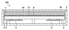
そのため、放射線撮影装置100の内部は、以下の構成をとっている。放射線入射方向の順から、筐体の放射線入射面である筐体上面3a(第一の部材)、第二の構成部材6(第二の部材)、放射線検出パネル1、第三の構成部材7(第三の部材)、放射線遮蔽部材8、そして、基台2(第四の部材)の順で構成されている。ここで、筐体上面3a(第一の部材)、第二の構成部材6(第二の部材)は放射線検出パネル1に対して放射線の入射方向側に配置されている。また、第三の構成部材7(第三の部材)、放射線遮蔽部材8、そして、基台2(第四の部材)は、放射線検出パネル1に対して放射線の入射方向の反対側に配置されている。かかる構成により、筐体上面3a側からの力により放射線検出パネル1にかかる引張応力を減らすことができる。
Therefore, the inside of the
放射線検出パネル1は、筐体上面3a(第一の部材)、基台2(第四の部材)の剛性より低い。筐体上面3a、および基台2の面積(A1)は、放射線入射方向からみて、放射線検出パネル1の面積(A2)と同じ面積(A1=A2)、または、それより大きい(A1>A2)。すなわち、筐体上面3a、および基台2のそれぞれの面積(A1)は、放射線入射方向からみて、放射線検出パネル1の面積以上(A1≧A2)である。このようにすることで、筐体側方からの衝撃が放射線検出パネル1に対して伝わりにくくし、パネルを安全に保持することができる。ここでさらに、第二の構成部材6、第三の構成部材7についても、同様に放射線検出パネル1の面積以上とすることで、より、放射線検出パネル1への衝撃を緩和することができる。
The radiation detection panel 1 is lower than the rigidity of the housing
第二の構成部材6および第三の構成部材7は筐体上面3a、放射線検出パネル1、基台2よりも材料のもつ弾性率が低い。第二の構成部材6の剛性は、第三の構成部材7の剛性と等しいか、あるいは第三の構成部材7の剛性より低い。また、第二の構成部材6の弾性率は、第三の構成部材7の弾性率と等しいか、あるいは第三の構成部材7の弾性率より低い。第三の構成部材7は、第二の構成部材6と比べて、材料のもつ弾性率が等しい、または、第二の構成部材6の弾性率より高い材料により構成されている。すなわち、第三の構成部材7の弾性率は第二の構成部材6の弾性率以上である(第三の構成部材7の弾性率≧第二の構成部材6の弾性率)という構成関係を有する。弾性率の小さい部材は弾性率の大きい部材に比べると変形しやすい。第二の構成部材6の弾性率は第三の構成部材7の弾性率と等しいか、あるいは第三の構成部材7の弾性率より低く、第二の構成部材6は第三の構成部材7に比べると変形しやすい。あるいは、第二の構成部材6は第三の構成部材7と同等に変形しやすい。そのため、外部から加えられる荷重に対する筐体上面3a等の変形を、第二の構成部材6の変形により吸収することで、変形の影響が放射線検出パネル1に及ぶのを防ぎ、放射線検出パネル1を保護することができる。
The second
外部から加えられる荷重に対する筐体上面3a等の変形を吸収するため、第二の構成部材6の板厚は第三の構成部材7の板厚と等しいか、あるいは第三の構成部材7の板厚より厚く構成されている。また、第二の構成部材6の弾性率は第三の構成部材7の弾性率と等しいか、あるいは第三の構成部材7の弾性率より低い。第二の構成部材6および第三の構成部材7は、緩衝材で構成されている。第二の構成部材6として、例えば、ゴム、フォーム、エラストマー、ゲルなどの弾性材料を使用することができる。また、第三の構成部材7として、第二の構成部材6のように、ゴム、フォーム、エラストマー、ゲルなどの弾性材料を使用することができるが、前述した関係を満たすことが可能な材料であれば、それに限らない。また、筐体上面3aは十分な剛性と、放射線の透過率の関係から炭素繊維強化プラスチック(CFRP)などを用いることが可能である。更に、基台2は十分な剛性を与える必要があるので、CFRPなどの繊維強化プラスチックや、マグネシウム合金、アルミニウム合金などの剛性が高い構造体で、筐体上面3aより高い剛性を有する。
In order to absorb deformation of the housing
筐体上面3a等よりも弾性率の低い材料により構成されている第二の構成部材6と第三の構成部材7によって、筐体上面3a等からの衝撃や変形などを吸収する効果が期待される。また、上述したように、上面側からの外力が加えられたときに、第二の構成部材6が第三の構成部材7に比べてひずみやすいので、放射線検出パネル1がひずみにくい構成となる。このため、放射線検出パネル1に対して、ひずみによる引張応力の発生を緩和できるため、高い保護効果が期待できる。更に、放射線検出パネル1の破損を軽減できるので、放射線撮影装置100で必要とされる剛性を下げることができ、放射線撮影装置100の軽量化や薄型化を図ることができる。
The second
一方で、前述した構成関係(第三の構成部材7の弾性率≧第二の構成部材6の弾性率)を変えて、第三の構成部材7が第二の構成部材6に比べてひずみやすい関係(第二の構成部材6の弾性率>第三の構成部材7の弾性率)をとる場合は以下のようになる。この場合、放射線検出パネル1に対して外力の緩和を行う機能はあるが、放射線検出パネル1が第三の構成部材7のひずみや変位に追従しやすくなるため、かえって放射線検出パネル1に負荷がかかりやすい構成となってしまう。
On the other hand, the third
基台2と第三の構成部材7との間には放射線遮蔽部材8が配置されている。放射線撮影装置100に入射した放射線は放射線検出パネル1を構成する蛍光体においてすべて吸収されずに、一部は放射線撮影装置100の内部を透過し、放射線撮影装置100の外部に放出される。このような放射線撮影装置100を透過した放射線が、背面の壁面や床などで散乱すると放射線撮影装置100に戻り、放射線検出パネル1に入射することがある。このような散乱放射線の構造体による透過率の差が画像として映りこむことになるため、できる限り抑制することが必要となる。放射線遮蔽部材8は、例えば、鉛(Pb)、バリウム(Ba)、タンタル(Ta)、モリブデン(Mo)、タングステン(W)のうち少なくともいずれか一つの重金属を含む材料、またはステンレス鋼などを用いて構成することができる。
A
本実施形態によれば、放射線検出パネル1の周りの部材の構成関係(機械的関係)を満たせば、放射線検出パネル1を外力による衝撃や変形から保護することができる。このため、剛性の高い構造体は、必ずしも筐体上面3aと基台2である必要はない。本実施形態によれば、従来に比べてガラスへの負荷が軽減できる構成をとることができるため、放射線撮影装置100の軽量化や薄型化が可能になる。
According to the present embodiment, the radiation detection panel 1 can be protected from impact and deformation due to an external force if the structural relationship (mechanical relationship) of the members around the radiation detection panel 1 is satisfied. For this reason, the highly rigid structure does not necessarily need to be the housing
(第2実施形態)
本実施形態では、放射線検出パネル1を筐体に接着した場合の構成例を説明する。図2は、第2実施形態に係る放射線撮影装置100の構成例を示す断面図である。第1実施形態と同じように、放射線検出パネル1は基台2に支持されている。放射線検出パネル1の読み出し制御や電気出力の処理を行う制御基板5は、フレキシブル回路基板4により放射線検出パネル1と接続されている。また、第1実施形態と同様に、放射線検出パネル1は、いわゆる表面入射構成でも、裏面入射構成でもよい。
(Second Embodiment)
In the present embodiment, a configuration example when the radiation detection panel 1 is bonded to a housing will be described. FIG. 2 is a cross-sectional view illustrating a configuration example of the
放射線撮影装置100を軽量化し、十分な放射線検出パネル1の保護を両立するために、放射線撮影装置100は、放射線検出パネル1と、放射線検出パネル1を覆う筐体3の放射線入射面である筐体上面3aと、を接着する構成がとられる。接着により、放射線撮影装置100の剛性が向上され、放射線検出パネル1を支持する基台2を省略した構成をとられることがある。基台2を省略することにより、制御基板5を配置する空間を増やし、更には、軽量化を目指した構成が可能になるという側面がある。
In order to reduce the weight of the
しかしながら、放射線撮影装置100には、撮影方式により筐体上面3aに大きな荷重が加わることが想定される。そのため、基台2を省略すると、層構成と曲げ応力の中立軸との関係で、外力が筐体上面3aに加わった場合に、放射線検出パネル1に強い引張応力が負荷されることになる。この引張応力は、放射線検出パネル1を構成するガラス基板の破壊原因となりやすい。
However, in the
そのため、放射線検出パネル1を適した構造関係の下に配置をしないと、放射線検出パネル1に強い引張応力が負荷されることが懸念され、放射線検出パネル1が、かえって保護しにくい構造になる。 Therefore, unless the radiation detection panel 1 is arranged under a suitable structural relationship, there is a concern that a strong tensile stress is applied to the radiation detection panel 1, and the radiation detection panel 1 becomes a structure that is difficult to protect.
また、前述したように、放射線検出パネル1を筐体上面3aに接着した接着構造では、全体で必要とされる剛性を維持するために、筐体上面3aなどで高い剛性を維持する必要がある。ここで、放射線発生装置から照射された放射線は、被写体と筐体上面3aとを通過したあと放射線検出パネル1において検出される。そのため筐体上面3aは、撮影した画像にアーチファクトとして残らないように、均一な板厚である単純な板状の形状をしたものが多い。そのため、必要剛性を確保するために、リブ状の構造をもたせるなどの形状を変えることが困難である。そのため、単純に板厚などを増して剛性を向上させるため、軽量化が困難となる。また、筐体上面3aに放射線検出パネル1を接着し一体化すると、筐体に外力などの負荷が加わった場合に、放射線検出パネル1へ、外力の伝達がされやすく、放射線検出パネル1への負荷が大きくなる懸念がある。
Further, as described above, in the bonding structure in which the radiation detection panel 1 is bonded to the housing
したがって、本実施形態では、上述のような影響を避けながら、放射線検出パネル1と高剛性部材との一体化による剛性の向上を図るため、放射線検出パネル1の周りは、図2に示すような構成をとる。 Therefore, in the present embodiment, in order to improve the rigidity by integrating the radiation detection panel 1 and the highly rigid member while avoiding the influence as described above, the periphery of the radiation detection panel 1 is as shown in FIG. Take the configuration.
図2では、放射線検出パネル1は、筐体3の放射線入射面である筐体上面3a、第二の構成部材61、第三の構成部材71、および基台2を含む部材と一体化されている。この時、筐体上面3aと放射線検出パネル1との間に配置する第二の構成部材61と、放射線検出パネル1と基台2との間に配置する第三の構成部材71とに、筐体上面3a、放射線検出パネル1、基台2より剛性(弾性率)の低い部材を使用する。
In FIG. 2, the radiation detection panel 1 is integrated with a member including a housing
また、第三の構成部材71は、第二の構成部材61と比べて、材料のもつ弾性率が等しい、または第二の構成部材61の弾性率よりも高い材料により構成されている。第二の構成部材61の弾性率は、第三の構成部材71の弾性率と等しいか、あるいは第三の構成部材71の弾性率より低い。第二の構成部材61の板厚は、第三の構成部材71の板厚と等しいか、あるいは第三の構成部材71の板厚より厚い。第三の構成部材71の厚みは第二の構成部材61の厚みより薄くする。
In addition, the
そして、それらの部材を接着し一体化する。これにより、外力からの緩衝効果と、一体化による剛性の向上を図ることが可能になる。また、基台2の剛性は筐体上面3aの剛性より大きい。
Then, these members are bonded and integrated. Thereby, it becomes possible to aim at the buffer effect from external force, and the rigidity improvement by integration. Moreover, the rigidity of the
筐体上面3aと放射線検出パネル1との間に配置する第二の構成部材61は、ゴム、フォーム、エラストマー、ゲルなどの弾性材料に、筐体上面3aや放射線検出パネル1と一体化できるように両面テープや接着材を両面に配置した部材により構成可能である。更に、放射線検出パネル1と放射線検出パネル1を支持する基台2との間に配置する第三の構成部材71は、第二の構成部材61と同じ、ゴム、フォーム、エラストマー、ゲルなどの弾性材料か、両面テープや接着材などの部材から構成することが可能である。第三の構成部材71として、例えば、前述した機械的関係を満たす材料であればよい。
The
また、筐体上面3aは十分な剛性と、放射線の透過率の関係からCFRPなどを用いることも可能である。更に、基台2は十分な剛性を与える必要があるので、CFRPなどの炭素繊維強化プラスチックや、マグネシウム合金、アルミニウム合金などの剛性が高い構造体であり、筐体上面3aより高い剛性を有する。
In addition, CFRP or the like can be used for the housing
以上のような構成で、放射線検出パネル1を筐体上面3aと基台2とに一体化する。このような構成とすることにより、放射線検出パネル1を構成するガラス基板に対して、筐体上面3aに放射線入射方向から外力が加わった場合に、ガラスの破壊原因となりやすい引張応力を緩和しやすいことが本願発明者によって見出されている。
With the configuration as described above, the radiation detection panel 1 is integrated with the housing
図3は、第二の構成部材61と第三の構成部材71の厚みの違いによる、放射線検出パネル1に荷重が加わった時の、放射線検出パネル1が破損される平均外力の関係を示した図である。筐体上面3aと基台2や放射線検出パネル1に関しては条件を変えずに、第二の構成部材61と第三の構成部材71の厚みだけを変えている。第二の構成部材61と第三の構成部材71は同一材料を用いている。また、荷重方向は図4に示すように、放射線入射方向から荷重を与えている。これは、放射線撮影装置100が、撮影方式によっては、放射線入射方向から高い荷重が加わりやすいためである。図3では、2つの部材のそれぞれの厚みをα、βとし、α<βの関係とする。厚みαの第二の構成部材61を第二(α)と表し、厚みβの第二の構成部材61を第二(β)と表す。同様に、厚みαの第三の構成部材71を第三(α)と表し、厚みβの第三の構成部材71を第三(β)と表す。図3に示すように、第二の構成部材61と第三の構成部材71の厚みを変えるだけで、放射線検出パネル1の破壊荷重が変化していることが分かる。特に、第二の構成部材61を厚くし、第三の構成部材71を薄くした方が破壊荷重は大きく上昇することが見いだせる(第二(β)、第三(α))。
FIG. 3 shows the relationship of the average external force that damages the radiation detection panel 1 when a load is applied to the radiation detection panel 1 due to the difference in thickness between the
図5は、図3の実験と同じ構成時に、一定荷重を加えた時の解析によって得られた放射線検出パネル1を構成するガラス部材の板厚と応力の関係を示す図である。ここでは、図3において破壊荷重の差が大きかった組み合わせとして、(第二(α)、第三(β))の組み合わせを実線で示し、(第二(β)、第三(α))の組み合わせを破線で示している。 FIG. 5 is a view showing the relationship between the thickness of the glass member constituting the radiation detection panel 1 and the stress obtained by the analysis when a constant load is applied in the same configuration as the experiment of FIG. Here, the combinations of (second (α), third (β)) are indicated by solid lines as combinations in which the difference in fracture load is large in FIG. 3, and (second (β), third (α)) Combinations are indicated by broken lines.
図5の縦軸はガラス部材の板厚を示し、横軸はガラス部材に加わる応力を示している。横軸の右側が引張応力で、左側が圧縮応力である。図5から分かるように、実線で示される(第二(α)、第三(β))の構成では、ガラス部材の全体に高い引張応力が負荷されているのが分かる。引張応力はガラス部材にとって破壊原因となりやすい。一方、破線で示される(第二(β)、第三(α))の組み合わせでは、引張応力が全体的に圧縮方向にシフトしている。この解析結果からも分かるように、ガラス部材にかかる応力状態は、放射線検出パネルの周辺の機械的関係によって大きく変化することが分かる。 The vertical axis in FIG. 5 indicates the plate thickness of the glass member, and the horizontal axis indicates the stress applied to the glass member. The right side of the horizontal axis is tensile stress, and the left side is compressive stress. As can be seen from FIG. 5, in the configuration of the second line (α) and the third line (β) indicated by solid lines, it can be seen that a high tensile stress is applied to the entire glass member. Tensile stress tends to cause breakage for glass members. On the other hand, in the combination of (second (β) and third (α)) indicated by broken lines, the tensile stress is entirely shifted in the compression direction. As can be seen from this analysis result, it can be seen that the stress state applied to the glass member varies greatly depending on the mechanical relationship around the radiation detection panel.
また同様に、第二の構成部材61と第三の構成部材71の弾性率や剛性の関係、筐体上面3aと基台2の剛性関係によっても放射線検出パネル1を保護するための機械的特性が変化することを本願発明者は見出している。
Similarly, mechanical characteristics for protecting the radiation detection panel 1 are also determined by the relationship between the elastic modulus and rigidity of the
本実施形態において、放射線検出パネル1は、筐体3の放射線入射面である筐体上面3a、第二の構成部材61、第三の構成部材71、および基台2を含む部材と一体化されている。この時、放射線の入射方向に配置されている筐体上面3aおよび第二の構成部材61を一体化した構造の剛性は、放射線の入射方向の反対側に配置されている第三の構成部材71および基台2を一体化した構造の剛性よりも低い。
In the present embodiment, the radiation detection panel 1 is integrated with a member including a housing
本実施形態によれば、放射線検出パネル1が破損する原因となる負荷を軽減することができ、放射線撮影装置で必要とされる剛性を減らすことができるので、放射線撮影装置の軽量化や薄型化を図ることができる。 According to the present embodiment, it is possible to reduce a load that causes damage to the radiation detection panel 1 and to reduce rigidity required for the radiation imaging apparatus. Can be achieved.
また、第1実施形態のように、基台2と第三の構成部材71との間に放射線遮蔽部材8を配置する。ここで放射線遮蔽部材は、鉛(Pb)、バリウム(Ba)、タンタル(Ta)、モリブデン(Mo)、タングステン(W)のうち少なくともいずれか一つの重金属を含む材料、またはステンレス鋼などを用いて構成することができる。
Moreover, the
本実施形態によれば、放射線検出パネル1の周りの部材の構成関係(機械的関係)を満たせば、放射線検出パネル1を外力による衝撃や変形から保護することができる。つまり、本実施形態によれば、従来に比べてガラスへの負荷を軽減できる構成をとることができるため、放射線撮影装置100の軽量化や薄型化が可能になる。
According to the present embodiment, the radiation detection panel 1 can be protected from impact and deformation due to an external force if the structural relationship (mechanical relationship) of the members around the radiation detection panel 1 is satisfied. That is, according to this embodiment, since the structure which can reduce the load to glass compared with the past can be taken, the weight reduction and thickness reduction of the
(第3実施形態)
本実施形態では、基台2を筐体3に締結した構成例を説明する。図6は、第3実施形態に係る放射線撮影装置100の構成例を示す断面図である。第1実施形態、および第2実施形態と同じように、放射線検出パネル1は基台2に支持され、放射線検出パネル1の読み出し制御や電気出力の処理を行う制御基板5は、フレキシブル回路基板4により放射線検出パネル1と接続されている。また、第1実施形態や第2実施形態と同様に、放射線検出パネル1は、いわゆる表面入射構成でも、裏面入射構成でもよい。
(Third embodiment)
In the present embodiment, a configuration example in which the
放射線撮影装置100の内部は、放射線検出パネル1を保護するために、第1実施形態や第2実施形態のように、以下の構成をとっている。放射線入射方向の順から、筐体の放射線入射面である筐体上面3a、第二の構成部材6、放射線検出パネル1、第三の構成部材7、放射線遮蔽部材8、そして、基台2の順で構成されている。
In order to protect the radiation detection panel 1, the inside of the
第二の構成部材6および第三の構成部材7の弾性率は筐体上面3a、放射線検出パネル1、基台2よりも材料のもつ弾性率が低い。第二の構成部材6の剛性は、第三の構成部材7の剛性と等しいか、あるいは第三の構成部材7の剛性より低い。また、第二の構成部材6の弾性率は、第三の構成部材7の弾性率と等しいか、あるいは第三の構成部材7の弾性率より低い。第三の構成部材7は、第二の構成部材6と比べて、材料のもつ弾性率が等しい、または、第二の構成部材6の弾性率より高い材料により構成されている。すなわち、第三の構成部材7の弾性率は第二の構成部材6の弾性率以上である(第三の構成部材7の弾性率≧第二の構成部材6の弾性率)という構成関係を有する。第二の構成部材6の弾性率は第三の構成部材7の弾性率と等しいか、あるいは第三の構成部材7の弾性率より低く、第二の構成部材6は第三の構成部材7に比べると変形しやすい。あるいは、第二の構成部材6は第三の構成部材7と同等に変形しやすい。そのため、外部から加えられる荷重に対する筐体上面3a等の局所的な変形を、第二の構成部材6の変形により吸収することで、局所的な変形の影響が放射線検出パネル1に及ぶのを防ぎ、放射線検出パネル1を保護することができる。
The elastic modulus of the
外部から加えられる荷重に対する筐体上面3a等の局所的な変形を吸収するため、第二の構成部材6の板厚は第三の構成部材7の板厚と等しいか、あるいは第三の構成部材7の板厚より厚く構成されている。また、第二の構成部材6の弾性率は第三の構成部材7の弾性率と等しいか、あるいは第三の構成部材7の弾性率より低い。第二の構成部材6および第三の構成部材7は、緩衝材で構成されている。第二の構成部材6として、例えば、ゴム、フォーム、エラストマー、ゲルなどの弾性材料を使用することができる。また、第三の構成部材7として、第二の構成部材6のように、ゴム、フォーム、エラストマー、ゲルなどの弾性材料を使用することができるが、前述した関係を満たすことが可能な材料であれば、それに限らない。また、筐体上面3aは十分な剛性と、放射線の透過率の関係からCFRPなどを用いることが可能である。更に、基台2は十分な剛性を与える必要があるので、CFRPなどの繊維強化プラスチックや、マグネシウム合金、アルミニウム合金などの剛性が高い構造体で、筐体上面3aより高い剛性を有する。
In order to absorb local deformation of the housing
しかし、それらの部材は、第2実施形態のように接着して一体化してもよいし、第1実施形態のように接着されなくてもよい。また、上述した一部の構成部材を接着したような構成でもよい。 However, these members may be bonded and integrated as in the second embodiment, or may not be bonded as in the first embodiment. Moreover, the structure which adhere | attached the one part structural member mentioned above may be sufficient.
図6では、放射線検出パネル1を支持する基台2の剛性を向上するために、基台2は筐体3に対して締結部材(例えば、ボルト、ビス、ピン)により締結されている。筐体3と基台2とが一体化するため、放射線撮影装置100の剛性を上げることができる。筐体3と基台2とが一体化して剛性が増えたため、その他の構成要素で必要とされる剛性を下げることが可能になる。これにより、放射線撮影装置100の軽量化や薄型化が可能になる。
In FIG. 6, the
本実施形態によれば、放射線検出パネル1の周りの部材の構成関係(機械的関係)を満たせば、放射線検出パネル1を外力による衝撃や変形から保護することができる。このため、剛性の高い構造体は、必ずしも筐体上面3aと基台2である必要はない。本実施形態によれば、従来に比べてガラスへの負荷が軽減できる構成をとることができるため、放射線撮影装置100の軽量化や薄型化が可能になる。
According to the present embodiment, the radiation detection panel 1 can be protected from impact and deformation due to an external force if the structural relationship (mechanical relationship) of the members around the radiation detection panel 1 is satisfied. For this reason, the highly rigid structure does not necessarily need to be the housing
上記の各実施形態によれば、放射線検出パネルを保護し、放射線撮影装置で必要とされる剛性を確保しながら、軽量化や薄型化が可能な放射線撮影装置の提供が可能になる。 According to each of the embodiments described above, it is possible to provide a radiation imaging apparatus that can be reduced in weight and thickness while protecting the radiation detection panel and ensuring rigidity required for the radiation imaging apparatus.
Claims (14)
前記放射線の入射方向側に配置された第一の部材および第二の部材と、
前記放射線の入射方向の反対側に配置された第三の部材および第四の部材と、
を備え、
前記第二の部材は前記第一の部材と前記放射線検出パネルとの間に配置され、
前記第三の部材は前記放射線検出パネルと前記第四の部材との間に配置され、
前記第二の部材および前記第三の部材の弾性率は、前記第一の部材および前記第四の部材の弾性率よりも低く、
前記第二の部材の弾性率は、前記第三の部材の弾性率と等しいか、あるいは前記第三の部材の弾性率より低い
ことを特徴とする放射線撮影装置。 A radiation detection panel for detecting radiation emitted from the radiation generating means;
A first member and a second member arranged on the incident direction side of the radiation;
A third member and a fourth member disposed on opposite sides of the incident direction of the radiation;
With
The second member is disposed between the first member and the radiation detection panel,
The third member is disposed between the radiation detection panel and the fourth member;
The elastic modulus of the second member and the third member is lower than the elastic modulus of the first member and the fourth member,
The radiation imaging apparatus, wherein the elastic modulus of the second member is equal to or lower than the elastic modulus of the third member.
Priority Applications (4)
| Application Number | Priority Date | Filing Date | Title |
|---|---|---|---|
| JP2013153829A JP2015025682A (en) | 2013-07-24 | 2013-07-24 | Radiographic device |
| CN201480040904.5A CN105393143A (en) | 2013-07-24 | 2014-07-15 | Radiation photographing apparatus |
| PCT/JP2014/003731 WO2015011894A1 (en) | 2013-07-24 | 2014-07-15 | Radiation photographing apparatus |
| US14/959,554 US9976897B2 (en) | 2013-07-24 | 2015-12-04 | Radiation imaging apparatus |
Applications Claiming Priority (1)
| Application Number | Priority Date | Filing Date | Title |
|---|---|---|---|
| JP2013153829A JP2015025682A (en) | 2013-07-24 | 2013-07-24 | Radiographic device |
Publications (2)
| Publication Number | Publication Date |
|---|---|
| JP2015025682A true JP2015025682A (en) | 2015-02-05 |
| JP2015025682A5 JP2015025682A5 (en) | 2016-09-08 |
Family
ID=52392959
Family Applications (1)
| Application Number | Title | Priority Date | Filing Date |
|---|---|---|---|
| JP2013153829A Pending JP2015025682A (en) | 2013-07-24 | 2013-07-24 | Radiographic device |
Country Status (4)
| Country | Link |
|---|---|
| US (1) | US9976897B2 (en) |
| JP (1) | JP2015025682A (en) |
| CN (1) | CN105393143A (en) |
| WO (1) | WO2015011894A1 (en) |
Families Citing this family (2)
| Publication number | Priority date | Publication date | Assignee | Title |
|---|---|---|---|---|
| JP6606388B2 (en) | 2015-09-29 | 2019-11-13 | キヤノン株式会社 | Radiography apparatus and radiation imaging system |
| JP7054356B2 (en) | 2018-03-20 | 2022-04-13 | キヤノン株式会社 | Radiation imaging device |
Citations (6)
| Publication number | Priority date | Publication date | Assignee | Title |
|---|---|---|---|---|
| JP2001346788A (en) * | 2000-06-09 | 2001-12-18 | Canon Inc | Radiographic apparatus |
| US20070085015A1 (en) * | 2005-10-14 | 2007-04-19 | Castleberry Donald E | Lightweight and rugged digital x-ray detector |
| WO2008018234A1 (en) * | 2006-08-11 | 2008-02-14 | Sharp Kabushiki Kaisha | Display apparatus and electronic apparatus with the same |
| JP2008212343A (en) * | 2007-03-02 | 2008-09-18 | General Electric Co <Ge> | Lightweight and robust digital x-ray detector |
| JP2009020099A (en) * | 2007-07-10 | 2009-01-29 | General Electric Co <Ge> | Digital x-ray detector |
| JP2013072808A (en) * | 2011-09-28 | 2013-04-22 | Fujifilm Corp | Cassette |
Family Cites Families (15)
| Publication number | Priority date | Publication date | Assignee | Title |
|---|---|---|---|---|
| JP3333278B2 (en) | 1993-07-14 | 2002-10-15 | 富士写真フイルム株式会社 | Radiation image detection method and radiation image detector |
| JP3066944B2 (en) | 1993-12-27 | 2000-07-17 | キヤノン株式会社 | Photoelectric conversion device, driving method thereof, and system having the same |
| JP3815766B2 (en) | 1998-01-28 | 2006-08-30 | キヤノン株式会社 | Two-dimensional imaging device |
| US7495226B2 (en) * | 2006-05-26 | 2009-02-24 | Carestream Health, Inc. | Compact and durable encasement for a digital radiography detector |
| JP4208907B2 (en) | 2006-07-24 | 2009-01-14 | キヤノン株式会社 | Radiation imaging equipment |
| US20080078940A1 (en) * | 2006-10-03 | 2008-04-03 | General Electric Company | Portable imaging device having shock absorbent assembly |
| US7488946B2 (en) * | 2006-10-03 | 2009-02-10 | General Electric Company | Digital x-ray detectors |
| JP5238652B2 (en) | 2009-09-11 | 2013-07-17 | 富士フイルム株式会社 | Radiation imaging equipment |
| JP5629445B2 (en) * | 2009-09-25 | 2014-11-19 | キヤノン株式会社 | X-ray imaging device |
| US9269741B2 (en) * | 2010-09-07 | 2016-02-23 | Konica Minolta Medical & Graphic, Inc. | Production method of radiation image detector and radiation image detector |
| JP2012078664A (en) | 2010-10-04 | 2012-04-19 | Fujifilm Corp | Radiation image photographing device, radiation image photographing system and method for repairing blemish of radiation image photographing device |
| US20130134319A1 (en) * | 2011-11-30 | 2013-05-30 | General Electric Company | Mechanical shock isolation for a radiographic device |
| JP2014074595A (en) * | 2012-10-02 | 2014-04-24 | Canon Inc | Radiation imaging apparatus, radiation imaging system, and method of manufacturing radiation imaging apparatus |
| JP6092568B2 (en) * | 2012-10-11 | 2017-03-08 | キヤノン株式会社 | Radiation detection apparatus and radiation detection system |
| JP6397208B2 (en) | 2014-04-09 | 2018-09-26 | キヤノン株式会社 | Radiographic imaging apparatus and radiographic imaging system |
-
2013
- 2013-07-24 JP JP2013153829A patent/JP2015025682A/en active Pending
-
2014
- 2014-07-15 WO PCT/JP2014/003731 patent/WO2015011894A1/en active Application Filing
- 2014-07-15 CN CN201480040904.5A patent/CN105393143A/en active Pending
-
2015
- 2015-12-04 US US14/959,554 patent/US9976897B2/en active Active
Patent Citations (6)
| Publication number | Priority date | Publication date | Assignee | Title |
|---|---|---|---|---|
| JP2001346788A (en) * | 2000-06-09 | 2001-12-18 | Canon Inc | Radiographic apparatus |
| US20070085015A1 (en) * | 2005-10-14 | 2007-04-19 | Castleberry Donald E | Lightweight and rugged digital x-ray detector |
| WO2008018234A1 (en) * | 2006-08-11 | 2008-02-14 | Sharp Kabushiki Kaisha | Display apparatus and electronic apparatus with the same |
| JP2008212343A (en) * | 2007-03-02 | 2008-09-18 | General Electric Co <Ge> | Lightweight and robust digital x-ray detector |
| JP2009020099A (en) * | 2007-07-10 | 2009-01-29 | General Electric Co <Ge> | Digital x-ray detector |
| JP2013072808A (en) * | 2011-09-28 | 2013-04-22 | Fujifilm Corp | Cassette |
Also Published As
| Publication number | Publication date |
|---|---|
| US9976897B2 (en) | 2018-05-22 |
| WO2015011894A1 (en) | 2015-01-29 |
| US20160084704A1 (en) | 2016-03-24 |
| CN105393143A (en) | 2016-03-09 |
Similar Documents
| Publication | Publication Date | Title |
|---|---|---|
| US9354333B2 (en) | Radiation detection apparatus and imaging system | |
| JP6397208B2 (en) | Radiographic imaging apparatus and radiographic imaging system | |
| US10061042B2 (en) | Radiation imaging apparatus and radiation imaging system | |
| US8592774B2 (en) | Radiographic apparatus | |
| US10119859B2 (en) | Radiation imaging apparatus having a buffer member in a corner and radiation imaging system | |
| JP4012182B2 (en) | Cassette type X-ray imaging device | |
| JP5629445B2 (en) | X-ray imaging device | |
| KR101387444B1 (en) | Apparatus for radiographic imaging | |
| JP6609105B2 (en) | Radiation imaging apparatus and radiation imaging system | |
| RU2608323C1 (en) | Radiation imaging device and radiation imaging system | |
| JP2008129231A (en) | Cassette type radiation image detector | |
| RU2637835C2 (en) | Beam imaging system | |
| JPWO2014080692A1 (en) | Portable radiographic imaging device | |
| WO2015011894A1 (en) | Radiation photographing apparatus | |
| JP6312445B2 (en) | Radiography apparatus and radiation imaging system | |
| JP6626548B2 (en) | Radiation image capturing apparatus and radiation image capturing system | |
| JP6184136B2 (en) | Radiation detector | |
| JP6824365B2 (en) | Radiation imaging equipment and radiation imaging system | |
| JP2022111805A (en) | Radiographic device |
Legal Events
| Date | Code | Title | Description |
|---|---|---|---|
| A521 | Request for written amendment filed |
Free format text: JAPANESE INTERMEDIATE CODE: A523 Effective date: 20160721 |
|
| A621 | Written request for application examination |
Free format text: JAPANESE INTERMEDIATE CODE: A621 Effective date: 20160721 |
|
| A131 | Notification of reasons for refusal |
Free format text: JAPANESE INTERMEDIATE CODE: A131 Effective date: 20170508 |
|
| A521 | Request for written amendment filed |
Free format text: JAPANESE INTERMEDIATE CODE: A523 Effective date: 20170629 |
|
| A131 | Notification of reasons for refusal |
Free format text: JAPANESE INTERMEDIATE CODE: A131 Effective date: 20171110 |
|
| A521 | Request for written amendment filed |
Free format text: JAPANESE INTERMEDIATE CODE: A523 Effective date: 20180109 |
|
| A02 | Decision of refusal |
Free format text: JAPANESE INTERMEDIATE CODE: A02 Effective date: 20180402 |