JP2015019496A - Transverse flux motor and vehicle - Google Patents

Transverse flux motor and vehicle Download PDF

Info

Publication number
JP2015019496A
JP2015019496A JP2013144729A JP2013144729A JP2015019496A JP 2015019496 A JP2015019496 A JP 2015019496A JP 2013144729 A JP2013144729 A JP 2013144729A JP 2013144729 A JP2013144729 A JP 2013144729A JP 2015019496 A JP2015019496 A JP 2015019496A
Authority
JP
Japan
Prior art keywords
magnetic
magnetic pole
rotor
stator
winding
Prior art date
Legal status (The legal status is an assumption and is not a legal conclusion. Google has not performed a legal analysis and makes no representation as to the accuracy of the status listed.)
Granted
Application number
JP2013144729A
Other languages
Japanese (ja)
Other versions
JP6081304B2 (en
Inventor
靖人 上田
Yasuto Ueda
靖人 上田
Current Assignee (The listed assignees may be inaccurate. Google has not performed a legal analysis and makes no representation or warranty as to the accuracy of the list.)
Toshiba Corp
Original Assignee
Toshiba Corp
Priority date (The priority date is an assumption and is not a legal conclusion. Google has not performed a legal analysis and makes no representation as to the accuracy of the date listed.)
Filing date
Publication date
Application filed by Toshiba Corp filed Critical Toshiba Corp
Priority to JP2013144729A priority Critical patent/JP6081304B2/en
Priority to US14/328,135 priority patent/US9787144B2/en
Priority to CN201410326867.6A priority patent/CN104283339A/en
Publication of JP2015019496A publication Critical patent/JP2015019496A/en
Application granted granted Critical
Publication of JP6081304B2 publication Critical patent/JP6081304B2/en
Active legal-status Critical Current
Anticipated expiration legal-status Critical

Links

Images

Classifications

    • HELECTRICITY
    • H02GENERATION; CONVERSION OR DISTRIBUTION OF ELECTRIC POWER
    • H02KDYNAMO-ELECTRIC MACHINES
    • H02K1/00Details of the magnetic circuit
    • H02K1/06Details of the magnetic circuit characterised by the shape, form or construction
    • H02K1/12Stationary parts of the magnetic circuit
    • H02K1/14Stator cores with salient poles
    • H02K1/145Stator cores with salient poles having an annular coil, e.g. of the claw-pole type
    • HELECTRICITY
    • H02GENERATION; CONVERSION OR DISTRIBUTION OF ELECTRIC POWER
    • H02KDYNAMO-ELECTRIC MACHINES
    • H02K1/00Details of the magnetic circuit
    • H02K1/06Details of the magnetic circuit characterised by the shape, form or construction
    • H02K1/12Stationary parts of the magnetic circuit
    • H02K1/16Stator cores with slots for windings
    • HELECTRICITY
    • H02GENERATION; CONVERSION OR DISTRIBUTION OF ELECTRIC POWER
    • H02KDYNAMO-ELECTRIC MACHINES
    • H02K1/00Details of the magnetic circuit
    • H02K1/06Details of the magnetic circuit characterised by the shape, form or construction
    • H02K1/22Rotating parts of the magnetic circuit
    • H02K1/24Rotor cores with salient poles ; Variable reluctance rotors
    • H02K1/243Rotor cores with salient poles ; Variable reluctance rotors of the claw-pole type
    • HELECTRICITY
    • H02GENERATION; CONVERSION OR DISTRIBUTION OF ELECTRIC POWER
    • H02KDYNAMO-ELECTRIC MACHINES
    • H02K1/00Details of the magnetic circuit
    • H02K1/06Details of the magnetic circuit characterised by the shape, form or construction
    • H02K1/22Rotating parts of the magnetic circuit
    • H02K1/26Rotor cores with slots for windings
    • HELECTRICITY
    • H02GENERATION; CONVERSION OR DISTRIBUTION OF ELECTRIC POWER
    • H02KDYNAMO-ELECTRIC MACHINES
    • H02K11/00Structural association of dynamo-electric machines with electric components or with devices for shielding, monitoring or protection
    • H02K11/20Structural association of dynamo-electric machines with electric components or with devices for shielding, monitoring or protection for measuring, monitoring, testing, protecting or switching
    • H02K11/21Devices for sensing speed or position, or actuated thereby
    • HELECTRICITY
    • H02GENERATION; CONVERSION OR DISTRIBUTION OF ELECTRIC POWER
    • H02KDYNAMO-ELECTRIC MACHINES
    • H02K19/00Synchronous motors or generators
    • H02K19/02Synchronous motors
    • H02K19/10Synchronous motors for multi-phase current
    • HELECTRICITY
    • H02GENERATION; CONVERSION OR DISTRIBUTION OF ELECTRIC POWER
    • H02KDYNAMO-ELECTRIC MACHINES
    • H02K2201/00Specific aspects not provided for in the other groups of this subclass relating to the magnetic circuits
    • H02K2201/12Transversal flux machines

Abstract

PROBLEM TO BE SOLVED: To provide a transverse flux motor that generates high torque.SOLUTION: A transverse flux motor includes a rotor and a stator. The rotor includes a first winding and first ferromagnetic body. The stator includes a second winding and a second ferromagnetic body. The first ferromagnetic body includes a first annular part, and a plurality of first magnetic poles and a plurality of second magnetic poles extending from the first annular part to the stator. One of each first magnetic pole and each second magnetic pole facing the first magnetic pole is formed so that its end faces the center of a facing surface of the stator and the rotor. The second ferromagnetic body includes a second annular part, and a plurality of third magnetic poles and a plurality of fourth magnetic poles extending from the second annular part to the rotor. One of each third magnetic pole and each fourth magnetic pole facing the third magnetic pole is formed so that its end faces the center of the facing surface.

Description

本発明の実施形態は、横方向磁束型回転電機及びこれを用いた車輌に関する。   Embodiments described herein relate generally to a transverse magnetic flux rotating electrical machine and a vehicle using the same.

従来の横方向磁束型回転電機では、固定子は回転子と同軸に巻かれた円環状コイルと円環状コイルを取り囲み円周上に配置されたU字型鉄心とで形成され、回転子は固定子の磁極に対向するように配置された永久磁石及び鉄心で形成される。この構造は広く知られている。   In the conventional transverse magnetic flux type rotating electrical machine, the stator is formed by an annular coil wound coaxially with the rotor and a U-shaped iron core that surrounds the annular coil and is arranged on the circumference, and the rotor is fixed. It is formed of a permanent magnet and an iron core arranged so as to face the magnetic poles of the child. This structure is well known.

固定子と回転子との回転方向における相対関係が異なる組み合わせは複数あり、それらの固定子の円環状コイルに多相交流を供給することによってトルクが発生する。この構造では、一般的に多極磁界を発生することが容易であり、高いトルクを得ることができる。   There are a plurality of combinations in which the relative relationship between the stator and the rotor in the rotational direction is different, and torque is generated by supplying multiphase alternating current to the annular coils of these stators. In this structure, it is generally easy to generate a multipolar magnetic field, and a high torque can be obtained.

特許第4709846号公報Japanese Patent No. 4709846

しかしながら、従来の横方向磁束型回転電機では、隣り合うU字型鉄心の間に空隙があるため、磁界が漏れやすい構造となっている。高トルク化を図るためには、このような磁界の漏れを低減する必要がある。   However, the conventional transverse magnetic flux type rotating electrical machine has a structure in which a magnetic field easily leaks because there is a gap between adjacent U-shaped iron cores. In order to achieve high torque, it is necessary to reduce such magnetic field leakage.

本発明が解決しようとする課題は、高いトルクを発生する横方向磁束型回転電機、及びこれを用いた車輌を提供することである。   The problem to be solved by the present invention is to provide a transverse magnetic flux type rotating electrical machine that generates a high torque and a vehicle using the same.

一実施形態に係る横方向磁束型回転電機は、回転軸周りに回転可能な回転子及び、前記回転子に対向して設けられた固定子を具備する。回転子は、回転方向に巻かれた第1の巻線と、前記第1の巻線を取り囲む第1の強磁性体と、を備える。固定子は、前記回転方向に巻かれた第2の巻線と、前記第2の巻線を取り囲む第2の強磁性体と、を備える。前記第1の強磁性体は、第1の環状部と、前記第1の環状部の一端部から前記固定子に向かって延びる複数の第1の磁極と、前記第1の環状部の他端部から前記固定子に向かって延びる複数の第2の磁極と、を備える。第1の磁極と該第1の磁極に対向する第2の磁極の一方は、先端が前記固定子と前記回転子との対向面の中央部に対向するように形成されている。前記第2の強磁性体は、第2の環状部と、前記第2の環状部の一端部から前記回転子に向かって延びる複数の第3の磁極と、前記第2の環状部の他端部から前記回転子に向かって延びる複数の第4の磁極と、を備える。第3の磁極と該第3の磁極に対向する第4の磁極との一方は、先端が前記対向面の中央部に対向するように形成されている。   A transverse magnetic flux rotating electrical machine according to an embodiment includes a rotor that can rotate around a rotation axis and a stator that is provided to face the rotor. The rotor includes a first winding wound in a rotation direction, and a first ferromagnetic body surrounding the first winding. The stator includes a second winding wound in the rotation direction, and a second ferromagnetic body surrounding the second winding. The first ferromagnetic body includes a first annular portion, a plurality of first magnetic poles extending from one end of the first annular portion toward the stator, and the other end of the first annular portion. A plurality of second magnetic poles extending from the portion toward the stator. One of the first magnetic pole and the second magnetic pole facing the first magnetic pole is formed so that the tip thereof faces the center of the facing surface between the stator and the rotor. The second ferromagnetic body includes a second annular portion, a plurality of third magnetic poles extending from one end portion of the second annular portion toward the rotor, and the other end of the second annular portion. A plurality of fourth magnetic poles extending from the portion toward the rotor. One of the third magnetic pole and the fourth magnetic pole facing the third magnetic pole is formed so that the tip faces the central portion of the facing surface.

第1の実施形態に係る回転電機を概略的に示す斜視図。The perspective view which shows roughly the rotary electric machine which concerns on 1st Embodiment. 図1に示した回転子及び固定子の概略構成を示す断面斜視図。FIG. 2 is a cross-sectional perspective view showing a schematic configuration of a rotor and a stator shown in FIG. 1. 図2の断面と極ピッチ分だけ異なる断面において、図1に示した回転子及び固定子の概略構成を示す断面斜視図。FIG. 3 is a cross-sectional perspective view showing a schematic configuration of the rotor and the stator shown in FIG. 1 in a cross-section different from the cross-section of FIG. 2 by a pole pitch. (a)及び(b)は図1の回転電機の部分断面図。(A) And (b) is a fragmentary sectional view of the rotary electric machine of FIG. (a)及び(b)は図1の回転電機の部分断面図。(A) And (b) is a fragmentary sectional view of the rotary electric machine of FIG. 第2の実施形態に係る回転電機を概略的に示す斜視図。The perspective view which shows roughly the rotary electric machine which concerns on 2nd Embodiment. 図6に示した回転子及び固定子の概略構成を示す断面斜視図。FIG. 7 is a cross-sectional perspective view showing a schematic configuration of a rotor and a stator shown in FIG. 6. 図7の断面と極ピッチ分だけ異なる断面において、図6に示した回転子及び固定子の概略構成を示す断面斜視図。FIG. 8 is a cross-sectional perspective view showing a schematic configuration of the rotor and the stator shown in FIG. 6 in a cross-section different from the cross-section of FIG. 7 by a pole pitch. (a)及び(b)は図6の回転電機の部分断面図。(A) And (b) is a fragmentary sectional view of the rotary electric machine of FIG. (a)及び(b)は図6の回転電機の部分断面図。(A) And (b) is a fragmentary sectional view of the rotary electric machine of FIG. 第3の実施形態に係る回転電機を概略的に示す斜視図。The perspective view which shows roughly the rotary electric machine which concerns on 3rd Embodiment. 図11に示した回転子及び固定子の概略構成を示す断面斜視図。FIG. 12 is a cross-sectional perspective view illustrating a schematic configuration of a rotor and a stator illustrated in FIG. 11. 図12の断面と極ピッチ分だけ異なる断面において、図11に示した回転子及び固定子の概略構成を示す断面斜視図。FIG. 13 is a cross-sectional perspective view showing a schematic configuration of the rotor and the stator shown in FIG. 11 in a cross-section different from the cross-section of FIG. 12 by a pole pitch. (a)及び(b)は図11の回転電機の部分断面図。(A) And (b) is a fragmentary sectional view of the rotary electric machine of FIG. (a)及び(b)は図11の回転電機の部分断面図。(A) And (b) is a fragmentary sectional view of the rotary electric machine of FIG. 第4の実施形態に係る回転電機を概略的に示す斜視図。The perspective view which shows roughly the rotary electric machine which concerns on 4th Embodiment. 図16に示した回転子及び固定子の概略構成を示す断面斜視図。FIG. 17 is a cross-sectional perspective view illustrating a schematic configuration of the rotor and the stator illustrated in FIG. 16. 図17の断面と極ピッチ分だけ異なる断面において、図16に示した回転子及び固定子の概略構成を示す断面斜視図。FIG. 18 is a cross-sectional perspective view showing a schematic configuration of the rotor and the stator shown in FIG. 16 in a cross-section different from the cross-section of FIG. 17 by a pole pitch. (a)及び(b)は図16の回転電機の部分断面図。(A) And (b) is a fragmentary sectional view of the rotary electric machine of FIG. (a)及び(b)は図16の回転電機の部分断面図。(A) And (b) is a fragmentary sectional view of the rotary electric machine of FIG. 第5の実施形態に係る回転電機駆動系を概略的に示すブロック図。The block diagram which shows roughly the rotary electric machine drive system which concerns on 5th Embodiment. 図21に示した駆動回路部の構成例を示すブロック図。FIG. 22 is a block diagram illustrating a configuration example of a drive circuit unit illustrated in FIG. 21. 図22に示した電機子巻線に流れる電流の一例を示すグラフ。The graph which shows an example of the electric current which flows into the armature winding shown in FIG. 図22に示した電機子巻線に流れる電流の他の例を示すグラフ。The graph which shows the other example of the electric current which flows into the armature winding shown in FIG. 第6の実施形態に係る車輌の一例を概略的に示すブロック図。The block diagram which shows roughly an example of the vehicle which concerns on 6th Embodiment. 第6の実施形態に係る車輌の他の例を概略的に示すブロック図。The block diagram which shows roughly the other example of the vehicle which concerns on 6th Embodiment. 第6の実施形態に係る車輌のさらに他の例を概略的に示すブロック図。FIG. 10 is a block diagram schematically showing still another example of the vehicle according to the sixth embodiment. 第6の実施形態に係る車輌のさらにまた他の例を概略的に示すブロック図。FIG. 10 is a block diagram schematically showing still another example of the vehicle according to the sixth embodiment.

以下、図面を参照しながら実施形態を説明する。なお、以下の実施形態では、同一の番号を付した部分については同様の動作を行うものとして、重ねての説明を省略する。   Hereinafter, embodiments will be described with reference to the drawings. Note that, in the following embodiments, the same numbered portions are assumed to perform the same operation, and repeated description is omitted.

(第1の実施形態)
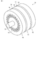
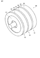
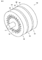
図1は、第1の実施形態に係る横方向磁束型の回転電機100を概略的に示す斜視図である。回転電機100は、図1に示すように、回転軸110、及び回転軸110を回転駆動する複数の(図1では3つの)駆動要素120を備える。これらの駆動要素120は、回転軸110が延伸する方向である軸方向に配置されている。駆動要素120の各々は回転子130及び固定子140を含む。回転電機100は、駆動要素120を収容する円筒形状の筐体(図示せず)をさらに備え、回転軸110は、筐体に設けられている1対の軸受けによって回転自在に支持されている。
(First embodiment)
FIG. 1 is a perspective view schematically showing a transverse magnetic flux type rotating electrical machine 100 according to the first embodiment. As shown in FIG. 1, the rotating electrical machine 100 includes a rotating shaft 110 and a plurality of (three in FIG. 1) driving elements 120 that rotationally drive the rotating shaft 110. These drive elements 120 are arranged in the axial direction, which is the direction in which the rotating shaft 110 extends. Each drive element 120 includes a rotor 130 and a stator 140. The rotating electrical machine 100 further includes a cylindrical housing (not shown) that houses the driving element 120, and the rotating shaft 110 is rotatably supported by a pair of bearings provided in the housing.

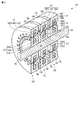
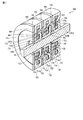
図2は、回転子130及び固定子140の概略構造を示す断面斜視図である。図2では、回転軸110を通り且つこの回転軸110に平行な仮想面に沿う回転電機100の断面が示されている。以下では、断面とは、回転軸110を通り且つ回転軸110に平行な仮想平面での断面、すなわち、回転子130の回転方向に垂直な方向に沿った断面を指す。図2に示すように、回転子130は、回転軸110に取り付けられ、回転軸110を介して互いに連結されている。回転子130は、回転軸110周りに回転可能である。固定子140間には非磁性の連結部材150が設けられ、これら連結部材150を介して固定子140は互いに連結されている。固定子140は筐体に固定されている。各駆動要素120では、回転子130及び固定子140は、軸方向に垂直な方向である径方向に、空隙を介して対向している。本実施形態では、回転子130は固定子140の内側に位置している。   FIG. 2 is a cross-sectional perspective view showing a schematic structure of the rotor 130 and the stator 140. In FIG. 2, a cross section of the rotating electrical machine 100 along a virtual plane passing through the rotation shaft 110 and parallel to the rotation shaft 110 is shown. Hereinafter, the cross section refers to a cross section in a virtual plane passing through the rotation axis 110 and parallel to the rotation axis 110, that is, a section along a direction perpendicular to the rotation direction of the rotor 130. As shown in FIG. 2, the rotor 130 is attached to the rotating shaft 110 and is connected to each other via the rotating shaft 110. The rotor 130 can rotate around the rotation axis 110. A nonmagnetic connecting member 150 is provided between the stators 140, and the stators 140 are connected to each other via these connecting members 150. The stator 140 is fixed to the housing. In each drive element 120, the rotor 130 and the stator 140 are opposed to each other with a gap in the radial direction that is a direction perpendicular to the axial direction. In the present embodiment, the rotor 130 is located inside the stator 140.

回転子130は、回転方向に巻かれた巻線(界磁巻線もしくは電機子巻線とも称する。)132と、巻線132を取り囲む強磁性体131と、を備える。強磁性体131は、回転軸110に結合される環状部133と、環状部133の一端部から固定子140に向かって延びる複数の磁極135Aと、環状部133の他端部から固定子140に向かって延びる複数の磁極135Bと、を含む。複数の磁極135Aは軸方向に巻線132を介して複数の磁極135Bにそれぞれ対向している。本実施形態の回転電機100には、回転子130に固定されている巻線132に電源を供給するために、回転しながら電気接点を有することができるスリップリング(図示せず)が設けられている。   The rotor 130 includes a winding 132 (also referred to as a field winding or an armature winding) wound in the rotation direction, and a ferromagnetic body 131 surrounding the winding 132. The ferromagnetic body 131 includes an annular portion 133 coupled to the rotating shaft 110, a plurality of magnetic poles 135 </ b> A extending from one end portion of the annular portion 133 toward the stator 140, and the other end portion of the annular portion 133 to the stator 140. A plurality of magnetic poles 135 </ b> B extending toward the surface. The plurality of magnetic poles 135A are opposed to the plurality of magnetic poles 135B via the windings 132 in the axial direction. The rotating electrical machine 100 of the present embodiment is provided with a slip ring (not shown) that can have electric contacts while rotating in order to supply power to the winding 132 fixed to the rotor 130. Yes.

ある磁極135Aは軸方向に対向している磁極135Bと対を成す。磁極135A及び対を成す磁極135Bの一方は直線的に径方向に延び、他方は先端が回転子130と固定子140との対向面の中央部に対向するように曲がっている。具体的には、曲っている方の磁極は、環状部133から直線的に径方向に延びる第1部分と、第1部分の先端から対向面の中央部に向かって直線的に延びる第2部分と、を含む。なお、曲がっている方の磁極は、図2に示すように所定の角度で折れ曲がった形状に形成される例に限らず、他の形状(例えば、滑らかに湾曲した形状)に形成されていてもよい。   A certain magnetic pole 135A is paired with a magnetic pole 135B facing in the axial direction. One of the magnetic pole 135 </ b> A and the pair of magnetic poles 135 </ b> B linearly extends in the radial direction, and the other is bent so that the tip is opposed to the central portion of the facing surface of the rotor 130 and the stator 140. Specifically, the bent magnetic pole includes a first portion that linearly extends from the annular portion 133 in the radial direction, and a second portion that extends linearly from the tip of the first portion toward the center portion of the opposing surface. And including. Note that the bent magnetic pole is not limited to an example in which the magnetic pole is bent at a predetermined angle as shown in FIG. 2, but may be formed in another shape (for example, a smoothly curved shape). Good.

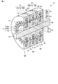
回転子130では、直線状の磁極と曲がった磁極が周方向に交互に配置されている。すなわち、磁極135Aが直線状の磁極であり且つ磁極135Bが曲がった磁極である第1の磁極形状パターンと、磁極135Aが曲がった磁極であり且つ磁極135Bが直線状の磁極である第2の磁極形状パターンとが、周方向に交互に繰り返されている。図2に示す断面から極ピッチ分だけ傾いた断面を図3に示す。図2及び図3に示すように、ある断面において強磁性体131が第1の磁極形状パターンを示す場合、極ピッチ分だけ異なる断面では、強磁性体131は第2の磁極形状パターンを示す。また、ある断面において強磁性体131が第2の磁極形状パターンを示す場合、極ピッチ分だけ異なる断面では、強磁性体131は第1の磁極形状パターンを示す。   In the rotor 130, linear magnetic poles and bent magnetic poles are alternately arranged in the circumferential direction. That is, the first magnetic pole shape pattern in which the magnetic pole 135A is a linear magnetic pole and the magnetic pole 135B is bent, and the second magnetic pole in which the magnetic pole 135A is a bent magnetic pole and the magnetic pole 135B is a linear magnetic pole. The shape pattern is alternately repeated in the circumferential direction. FIG. 3 shows a cross section inclined by the pole pitch from the cross section shown in FIG. As shown in FIGS. 2 and 3, when the ferromagnetic body 131 shows the first magnetic pole shape pattern in a certain cross section, the ferromagnetic body 131 shows the second magnetic pole shape pattern in a cross section different by the pole pitch. Further, when the ferromagnetic body 131 shows the second magnetic pole shape pattern in a certain cross section, the ferromagnetic body 131 shows the first magnetic pole shape pattern in a cross section different by the pole pitch.

一方、固定子140は、回転方向に巻かれた巻線(電機子巻線もしくは界磁巻線とも称する。)142と、巻線142を取り囲む強磁性体141と、を備える。強磁性体141は、環状部143と、環状部143の一端部から回転子130に向かって延びる複数の磁極145Aと、環状部143の他端部から回転子130に向かって延びる複数の磁極145Bと、を含む。複数の磁極145Aは軸方向に巻線132を介して複数の磁極145Bにそれぞれ対向している。   On the other hand, the stator 140 includes a winding (also referred to as an armature winding or a field winding) 142 wound in the rotation direction, and a ferromagnetic body 141 surrounding the winding 142. The ferromagnetic body 141 includes an annular portion 143, a plurality of magnetic poles 145A extending from one end of the annular portion 143 toward the rotor 130, and a plurality of magnetic poles 145B extending from the other end of the annular portion 143 toward the rotor 130. And including. The plurality of magnetic poles 145A are opposed to the plurality of magnetic poles 145B via the windings 132 in the axial direction.

ある磁極145Aは軸方向に対向している磁極145Bと対を成す。磁極145A及び対を成す磁極145Bの一方は直線的に径方向に延び、他方は先端が回転子130と固定子140との対向面の中央部に対向するように曲がっている。具体的には、曲っている方の磁極は、環状部143から直線的に径方向に延びる第1部分と、第1部分の先端から対向面の中央部に向かって直線的に延びる第2部分と、を含む。なお、曲がっている方の磁極は、図2に示すように所定の角度で折れ曲がった形状に形成される例に限らず、他の形状(例えば、滑らかに湾曲した形状)に形成されていてもよい。   A certain magnetic pole 145A is paired with a magnetic pole 145B facing in the axial direction. One of the magnetic pole 145 </ b> A and the pair of magnetic poles 145 </ b> B linearly extends in the radial direction, and the other is bent so that the tip is opposed to the central portion of the facing surface between the rotor 130 and the stator 140. Specifically, the bent magnetic pole includes a first portion that linearly extends from the annular portion 143 in the radial direction, and a second portion that extends linearly from the tip of the first portion toward the center portion of the opposing surface. And including. Note that the bent magnetic pole is not limited to an example in which the magnetic pole is bent at a predetermined angle as shown in FIG. 2, but may be formed in another shape (for example, a smoothly curved shape). Good.

固定子140では、直線状の磁極と曲がった磁極が周方向に交互に配置されている。すなわち、磁極145Aが直線状の磁極であり且つ磁極145Bが曲がった磁極である第3の磁極形状パターンと、磁極145Aが曲がった磁極であり且つ磁極145Bが直線状の磁極である第4の磁極形状パターンとが、周方向に交互に繰り返されている。図2及び図3に示すように、ある断面において強磁性体141が第3の磁極形状パターンを示す場合、極ピッチ分だけ異なる断面では、強磁性体141は第4の磁極形状パターンを示す。また、ある断面において強磁性体141が第4の磁極形状パターンを示す場合、極ピッチ分だけ異なる断面では、強磁性体141は第3の磁極形状パターンを示す。   In the stator 140, linear magnetic poles and bent magnetic poles are alternately arranged in the circumferential direction. That is, the third magnetic pole shape pattern in which the magnetic pole 145A is a linear magnetic pole and the magnetic pole 145B is a bent magnetic pole, and the fourth magnetic pole in which the magnetic pole 145A is a bent magnetic pole and the magnetic pole 145B is a linear magnetic pole. The shape pattern is alternately repeated in the circumferential direction. As shown in FIGS. 2 and 3, when the ferromagnetic body 141 shows the third magnetic pole shape pattern in a certain cross section, the ferromagnetic body 141 shows the fourth magnetic pole shape pattern in a cross section different by the pole pitch. Further, when the ferromagnetic body 141 shows the fourth magnetic pole shape pattern in a certain cross section, the ferromagnetic body 141 shows the third magnetic pole shape pattern in a cross section different by the pole pitch.

各駆動要素120では、巻線132及び142に電流を供給することによりトルクが発生する。トルクが発生するメカニズムは後述する。発生したトルクによって回転子130が回転され、それにより回転軸110が回転される。本実施形態では、3つの駆動要素120は、回転方向の相対的な位相が異なる。そのため、これらの駆動要素120の巻線132及び142に供給する電流の割合を調整することで、トルクを制御することができる。
なお、駆動要素120は、図1に示すような3つ設けられる例に限らず、1つ、2つ、又は4つ以上設けられていてもよい。
In each drive element 120, torque is generated by supplying current to the windings 132 and 142. A mechanism for generating torque will be described later. The rotor 130 is rotated by the generated torque, whereby the rotating shaft 110 is rotated. In the present embodiment, the three drive elements 120 have different relative phases in the rotational direction. Therefore, the torque can be controlled by adjusting the ratio of the current supplied to the windings 132 and 142 of these drive elements 120.
The number of drive elements 120 is not limited to the example shown in FIG. 1, but may be one, two, or four or more.

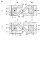
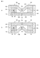
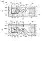
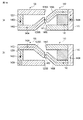
次に、図4(a)及び(b)並びに図5(a)及び(b)を参照して各駆動要素120がトルクを発生するメカニズムについて説明する。
ある回転角度では、図4(a)に示すような回転子130の曲がった磁極135Bと固定子140の曲がった磁極145Aが対向する部分と、図4(b)に示すような回転子130の曲がった磁極135Aと固定子140の曲がった磁極145Bが対向する部分と、が隣り合って存在する。他の回転角度では、図5(a)に示すように、回転子130の曲がった磁極135Aと固定子140の曲がった磁極145Aが対向し、且つ、回転子130の直線状の磁極135Bと固定子140の直線状の磁極145Bが対向する。図5(a)に示す部分と隣り合う部分では、図5(b)に示すように、回転子130の直線状の磁極135Aと固定子140の直線状の磁極145Aが対向し、且つ、回転子130の曲がった磁極135Bと固定子140の曲がった磁極145Bが対向する。
Next, the mechanism by which each drive element 120 generates torque will be described with reference to FIGS. 4 (a) and 4 (b) and FIGS. 5 (a) and 5 (b).
At a certain rotation angle, the bent magnetic pole 135B of the rotor 130 as shown in FIG. 4A and the bent magnetic pole 145A of the stator 140 face each other, and the rotor 130 as shown in FIG. A portion where the bent magnetic pole 135A and the bent magnetic pole 145B of the stator 140 are opposed to each other exists adjacent to each other. At other rotation angles, as shown in FIG. 5A, the bent magnetic pole 135A of the rotor 130 and the bent magnetic pole 145A of the stator 140 face each other and are fixed to the linear magnetic pole 135B of the rotor 130. The linear magnetic poles 145B of the child 140 are opposed to each other. In a portion adjacent to the portion shown in FIG. 5A, the linear magnetic pole 135A of the rotor 130 and the linear magnetic pole 145A of the stator 140 face each other and rotate as shown in FIG. 5B. The bent magnetic pole 135B of the child 130 and the bent magnetic pole 145B of the stator 140 face each other.

図4(a)及び(b)に示す部分では、回転子130の巻線132に電流401を流すことによって磁気回路402が形成され、矢印403で示される向きに磁束が流れる。この磁束は回転子130の環状部133及び固定子140の環状部143において周方向(図4(a)及び(b)では紙面に垂直な方向に対応する。)にも流れ、それにより、図4(a)及び(b)に示す2つの部分にわたって磁気回路402が形成される。磁気回路402は励磁した巻線132に鎖交するように形成される。具体的には、巻線132を励磁すると、環状部133、磁極135B、空隙411、磁極145A、環状部143、磁極145B、空隙412、磁極135A、環状部133の経路で磁束が流れる。固定子140の巻線142を励磁する場合にも、磁気回路402と同様の経路を磁束が流れる。巻線132の励磁によって発生する磁束と巻線142の励磁によって発生する磁束とが相互作用し、その結果、トルクが発生する。   4A and 4B, a magnetic circuit 402 is formed by passing a current 401 through the winding 132 of the rotor 130, and a magnetic flux flows in the direction indicated by the arrow 403. This magnetic flux also flows in the circumferential direction (corresponding to the direction perpendicular to the paper surface in FIGS. 4 (a) and 4 (b)) in the annular portion 133 of the rotor 130 and the annular portion 143 of the stator 140. The magnetic circuit 402 is formed over two parts shown in 4 (a) and 4 (b). The magnetic circuit 402 is formed so as to interlink with the excited winding 132. Specifically, when the winding 132 is excited, a magnetic flux flows through the path of the annular portion 133, the magnetic pole 135 B, the air gap 411, the magnetic pole 145 A, the annular portion 143, the magnetic pole 145 B, the air gap 412, the magnetic pole 135 A, and the annular portion 133. Even when the winding 142 of the stator 140 is excited, the magnetic flux flows through the same path as the magnetic circuit 402. The magnetic flux generated by the excitation of the winding 132 interacts with the magnetic flux generated by the excitation of the winding 142, and as a result, torque is generated.

図5(a)に示す部分では、回転子130の巻線132に電流501を流すことによって磁気回路502が形成される。磁気回路502では、磁束は矢印503で示される向きに流れる。この場合、磁束は、回転子130の環状部133及び固定子140の環状部143において周方向(図5(a)では紙面に垂直な方向に対応する。)には流れず、励磁した巻線132に鎖交するように、断面内で閉じた磁気回路502が形成される。具体的には、巻線132を励磁すると、環状部133、磁極135B、空隙511、磁極145B、環状部143、磁極145A、空隙512、磁極135A、環状部133の経路で磁束が流れる。固定子140の巻線142を励磁する場合にも、磁気回路502と同様の経路を磁束が流れる。巻線132の励磁によって発生する磁束と巻線142の励磁によって発生する磁束とが相互作用し、その結果、トルクが発生する。   In the part shown in FIG. 5A, a magnetic circuit 502 is formed by passing a current 501 through the winding 132 of the rotor 130. In the magnetic circuit 502, the magnetic flux flows in the direction indicated by the arrow 503. In this case, the magnetic flux does not flow in the circumferential direction (corresponding to the direction perpendicular to the paper surface in FIG. 5A) in the annular portion 133 of the rotor 130 and the annular portion 143 of the stator 140, and the excited winding. A magnetic circuit 502 closed in the cross section is formed so as to be linked to 132. Specifically, when the winding 132 is excited, magnetic flux flows through the path of the annular portion 133, the magnetic pole 135 B, the air gap 511, the magnetic pole 145 B, the annular portion 143, the magnetic pole 145 A, the air gap 512, the magnetic pole 135 A, and the annular portion 133. Even when the winding 142 of the stator 140 is excited, the magnetic flux flows through the same path as the magnetic circuit 502. The magnetic flux generated by the excitation of the winding 132 interacts with the magnetic flux generated by the excitation of the winding 142, and as a result, torque is generated.

図5(b)に示す部分では、回転子130の巻線132に電流501を流すことによって磁気回路504が形成される。磁気回路504では、磁束は矢印505で示される向きに流れる。この場合、磁束は、回転子130の環状部133及び固定子140の環状部143において周方向(図5(b)では紙面に垂直な方向に対応する。)には流れず、励磁した巻線132に鎖交するように、断面内で閉じた磁気回路504が形成される。具体的には、巻線132を励磁すると、環状部133、磁極135B、空隙513、磁極145B、環状部143、磁極145A、空隙514、磁極135A、環状部133の経路で磁束が流れる。固定子140の巻線142を励磁する場合にも、磁気回路504と同様の経路を磁束が流れる。巻線132の励磁によって発生する磁束と巻線142の励磁によって発生する磁束とが相互作用し、その結果、トルクが発生する。   In the part shown in FIG. 5B, a magnetic circuit 504 is formed by passing a current 501 through the winding 132 of the rotor 130. In the magnetic circuit 504, the magnetic flux flows in the direction indicated by the arrow 505. In this case, the magnetic flux does not flow in the circumferential direction (corresponding to a direction perpendicular to the paper surface in FIG. 5B) in the annular portion 133 of the rotor 130 and the annular portion 143 of the stator 140, and the excited winding. A magnetic circuit 504 closed in the cross section is formed so as to be linked to 132. Specifically, when the winding 132 is excited, magnetic flux flows through the path of the annular part 133, the magnetic pole 135 B, the air gap 513, the magnetic pole 145 B, the annular part 143, the magnetic pole 145 A, the air gap 514, the magnetic pole 135 A, and the annular part 133. Even when the winding 142 of the stator 140 is excited, the magnetic flux flows through the same path as the magnetic circuit 504. The magnetic flux generated by the excitation of the winding 132 interacts with the magnetic flux generated by the excitation of the winding 142, and as a result, torque is generated.

本実施形態では、回転子130に関して、磁極135Aが直線状の磁極であり且つ磁極135Bが曲がった磁極である第1の磁極形状パターンと、磁極135Aが曲がった磁極であり且つ磁極135Bが直線状の磁極である第2の磁極形状パターンと、が周方向に周期的に交互に繰り返されている。さらに、固定子140に関して、磁極145Aが直線状の磁極であり且つ磁極145Bが曲がった磁極である第3の磁極形状パターンと、磁極145Aが曲がった磁極であり且つ磁極145Bが直線状の磁極である第4の磁極形状パターンと、が周方向に周期的に交互に繰り返されている。これにより、巻線132及び142を励磁した場合には、回転電機100のいずれの断面においても、図4(a)及び(b)に示した磁気回路402、図5(a)に示した磁気回路502、及び図5(b)に示した磁気回路504のいずれかが形成される。   In the present embodiment, with respect to the rotor 130, the first magnetic pole shape pattern in which the magnetic pole 135A is a linear magnetic pole and the magnetic pole 135B is bent, and the magnetic pole 135A is a bent magnetic pole and the magnetic pole 135B is linear. The second magnetic pole shape pattern which is the magnetic poles of the first and second magnetic poles are periodically and alternately repeated in the circumferential direction. Further, regarding the stator 140, the third magnetic pole shape pattern in which the magnetic pole 145A is a linear magnetic pole and the magnetic pole 145B is a bent magnetic pole, and the magnetic pole 145A is a bent magnetic pole and the magnetic pole 145B is a linear magnetic pole. A certain fourth magnetic pole shape pattern is periodically and alternately repeated in the circumferential direction. Thus, when the windings 132 and 142 are excited, the magnetic circuit 402 shown in FIGS. 4A and 4B and the magnetic circuit shown in FIG. Either the circuit 502 or the magnetic circuit 504 shown in FIG. 5B is formed.

具体的には、ある断面において、図5(a)に示すように、回転子130と固定子140との位置関係がそれらの対向面に対して対称となっている場合に、磁極135Aと磁極145Aが対向し且つ磁極135Bと磁極145Bが対向する。これにより、その断面内で閉じた磁気回路502が形成される。同様に、他の断面において、図5(b)に示すように、回転子130と固定子140との位置関係がそれらの対向面に対して対称となっている場合に、磁極135Aと磁極145Aが対向し且つ磁極135Bと磁極145Bが対向する。これにより、その断面内で閉じた磁気回路504が形成される。さらに、閉じた磁気回路502及び504が発生しない断面では、図4(a)及び(b)に示すように、屈曲した磁極135Aと145Bの組、屈曲した磁極135Bと磁極145Aの組、並びに、環状部133及び143を通じて磁気回路402が形成される。このように、本実施形態では、いずれの断面においても磁気回路が形成されるので、磁界の漏れを低減することができ、大きな磁極面積を確保することができる。その結果、高トルク化を実現することができる。   Specifically, in a certain cross section, when the positional relationship between the rotor 130 and the stator 140 is symmetric with respect to their opposing surfaces as shown in FIG. 5A, the magnetic pole 135A and the magnetic pole 145A faces and magnetic pole 135B and magnetic pole 145B face each other. Thereby, the magnetic circuit 502 closed in the cross section is formed. Similarly, in the other cross section, when the positional relationship between the rotor 130 and the stator 140 is symmetric with respect to their opposing surfaces, as shown in FIG. 5B, the magnetic pole 135A and the magnetic pole 145A. And the magnetic pole 135B and the magnetic pole 145B face each other. Thereby, the magnetic circuit 504 closed in the cross section is formed. Further, in the cross section where the closed magnetic circuits 502 and 504 are not generated, as shown in FIGS. 4A and 4B, a set of bent magnetic poles 135A and 145B, a set of bent magnetic poles 135B and 145A, and A magnetic circuit 402 is formed through the annular portions 133 and 143. Thus, in this embodiment, since a magnetic circuit is formed in any cross section, leakage of a magnetic field can be reduced and a large magnetic pole area can be ensured. As a result, high torque can be realized.

さらに、本実施形態では、回転子130及び固定子140それぞれを一体成形することができるので、機械的強度を向上させることができる。また、回転子130及び固定子140それぞれに環状に巻かれた巻線132及び142を取り付ける構造とすることで、組み立て工数を低減することができる。また、界磁巻線(巻線132又は142)を設けることにより、駆動速度に適した界磁磁界を制御する際に、永久磁石を用いた従来の回転電機とは異なり、電機子巻線132の負の直軸電流による銅損、その電流から発生する逆磁場による永久磁石の減磁がなく、可変速領域の広い駆動も可能になる。   Furthermore, in this embodiment, since the rotor 130 and the stator 140 can be integrally formed, the mechanical strength can be improved. Further, the assembly man-hour can be reduced by adopting a structure in which the windings 132 and 142 wound in an annular shape are attached to the rotor 130 and the stator 140, respectively. In addition, when a field magnetic field (winding 132 or 142) is provided to control a field magnetic field suitable for the driving speed, the armature winding 132 is different from a conventional rotating electric machine using a permanent magnet. Thus, there is no copper loss due to the negative straight axis current, and the demagnetization of the permanent magnet due to the reverse magnetic field generated from the current, and wide driving in the variable speed region is also possible.

以上のように、第1の実施形態に係る回転電機100では、回転子130に設けられる磁極135A及び135Bの一方の先端部が回転子130と固定子140との対向面の中央側に曲がり、固定子140に設けられる磁極145A及び145Bの一方の先端部が回転子130と固定子140との対向面の中央側に曲がっている。これにより、巻線132及び142を励磁した場合には、いずれの断面においても磁気回路が形成される。その結果、高いトルクを発生することが可能になる。   As described above, in the rotating electrical machine 100 according to the first embodiment, one tip portion of the magnetic poles 135A and 135B provided in the rotor 130 bends to the center side of the facing surface between the rotor 130 and the stator 140, One end of each of the magnetic poles 145A and 145B provided on the stator 140 is bent toward the center of the opposing surface of the rotor 130 and the stator 140. Thus, when the windings 132 and 142 are excited, a magnetic circuit is formed in any cross section. As a result, high torque can be generated.

(第2の実施形態)
第2の実施形態に係る回転電機の基本的な構成は、第1の実施形態に係る回転電機と同様である。第2の実施形態は、電機子巻線が回転子から機械的に分離されている点が第1の実施形態と異なる。
図6は、第2の実施形態に係る回転電機600を概略的に示す斜視図であり、図7及び図8は、回転子130及び固定子140の概略構造を示す断面斜視図である。図8に示す断面は、図7に示す断面から極ピッチ分だけ傾いた断面である。さらに、図9(a)及び(b)並びに図10(a)及び(b)は、回転電機600の部分断面図である。
(Second Embodiment)
The basic configuration of the rotating electrical machine according to the second embodiment is the same as that of the rotating electrical machine according to the first embodiment. The second embodiment is different from the first embodiment in that the armature winding is mechanically separated from the rotor.
FIG. 6 is a perspective view schematically showing a rotating electrical machine 600 according to the second embodiment, and FIGS. 7 and 8 are cross-sectional perspective views showing a schematic structure of the rotor 130 and the stator 140. The cross section shown in FIG. 8 is a cross section inclined by the pole pitch from the cross section shown in FIG. Further, FIGS. 9A and 9B and FIGS. 10A and 10B are partial cross-sectional views of the rotating electrical machine 600.

図6に示す回転電機600では、図7及び図8に示すように、回転子130は、環状の強磁性体731、732、及びこれらの強磁性体731、732を機械的に結合する環状の非磁性体733を備える。強磁性体731は、環状部133、及び環状部133から固定子140に向かって延びる複数の磁極135Bを含む。強磁性体732は、固定子140に向かって延びる複数の磁極135Aを含む。磁極135Aは非磁性体733によって磁極135Bに結合されている。   In the rotating electrical machine 600 shown in FIG. 6, as shown in FIGS. 7 and 8, the rotor 130 includes annular ferromagnets 731 and 732, and annular ferromagnets 731 and 732 mechanically coupled to each other. A non-magnetic material 733 is provided. The ferromagnetic body 731 includes an annular portion 133 and a plurality of magnetic poles 135 </ b> B extending from the annular portion 133 toward the stator 140. The ferromagnetic body 732 includes a plurality of magnetic poles 135 </ b> A extending toward the stator 140. The magnetic pole 135A is coupled to the magnetic pole 135B by a non-magnetic material 733.

強磁性体731及び732間には、強磁性体734と強磁性体734に取り付けられた巻線132とが介挿されている。より具体的には、強磁性体734は、強磁性体732と環状部133との間に配置され、巻線132は、強磁性体731、非磁性体733、強磁性体734により囲まれる空間に配置されている。強磁性体734及び巻線132は、回転中の回転子130に接触することがないように、回転軸110を中心とした環状に形成されている。強磁性体734は、非磁性の連結部材601及び連結部材150を介して固定子140に固定されている。本実施形態では、巻線132は回転子130から分離されているので、スリップリングを設ける必要がない。   A ferromagnetic body 734 and a winding 132 attached to the ferromagnetic body 734 are interposed between the ferromagnetic bodies 731 and 732. More specifically, the ferromagnetic body 734 is disposed between the ferromagnetic body 732 and the annular portion 133, and the winding 132 is a space surrounded by the ferromagnetic body 731, the nonmagnetic body 733, and the ferromagnetic body 734. Is arranged. The ferromagnetic body 734 and the winding 132 are formed in an annular shape around the rotation shaft 110 so as not to contact the rotating rotor 130. The ferromagnetic body 734 is fixed to the stator 140 via the nonmagnetic connecting member 601 and the connecting member 150. In this embodiment, since the winding 132 is separated from the rotor 130, it is not necessary to provide a slip ring.

ある回転角度では、図9(a)に示すような曲がった磁極135Bと曲がった磁極145Aが対向する部分と、図9(b)に示すような曲がった磁極135Aと曲がった磁極145Bが対向する部分と、が隣り合って存在する。他の回転角度では、図10(a)に示すように、曲がった磁極135Aと曲がった磁極145Aが対向し、且つ、直線状の磁極135Bと直線状の磁極145Bが対向する。図10(a)に示す部分と隣り合う部分では、図10(b)に示すように、直線状の磁極135Aと直線状の磁極145Aが対向し、且つ、曲がった磁極135Bと曲がった磁極145Bが対向する。   At a certain rotation angle, the bent magnetic pole 135B and the bent magnetic pole 145A as shown in FIG. 9 (a) face each other, and the bent magnetic pole 135A and the bent magnetic pole 145B as shown in FIG. 9 (b) face each other. The part exists next to each other. At other rotation angles, as shown in FIG. 10A, the bent magnetic pole 135A and the bent magnetic pole 145A are opposed to each other, and the linear magnetic pole 135B and the linear magnetic pole 145B are opposed to each other. In a portion adjacent to the portion shown in FIG. 10A, as shown in FIG. 10B, the linear magnetic pole 135A and the linear magnetic pole 145A face each other, and the bent magnetic pole 135B and the bent magnetic pole 145B are provided. Opposite.

図9(a)及び(b)に示す部分では、巻線132に電流901を流すことによって磁気回路902が形成され、矢印903で示される向きに磁束が流れる。この磁束は回転子130の環状部133及び固定子140の環状部143において周方向(図9(a)及び(b)では紙面に垂直な方向に対応する。)にも流れ、それにより、図9(a)及び(b)に示す2つの部分にわたって磁気回路902が形成される。磁気回路902は励磁した巻線132に鎖交するように形成される。具体的には、巻線132を励磁すると、環状部133、磁極135B、空隙911、磁極145A、環状部143、磁極145B、空隙912、磁極135A、空隙913、強磁性体734、空隙914、環状部133の経路で磁束が流れる。巻線142を励磁する場合にも、磁気回路902と同様の経路を磁束が流れる。巻線132の励磁によって発生する磁束と巻線142の励磁によって発生する磁束とが相互作用し、その結果、トルクが発生する。   9A and 9B, a magnetic circuit 902 is formed by passing a current 901 through the winding 132, and a magnetic flux flows in the direction indicated by the arrow 903. This magnetic flux also flows in the circumferential direction (corresponding to the direction perpendicular to the paper surface in FIGS. 9A and 9B) in the annular portion 133 of the rotor 130 and the annular portion 143 of the stator 140, thereby 9 (a) and 9 (b), a magnetic circuit 902 is formed over two portions. The magnetic circuit 902 is formed so as to interlink with the excited winding 132. Specifically, when the winding 132 is excited, the annular portion 133, the magnetic pole 135B, the air gap 911, the magnetic pole 145A, the annular portion 143, the magnetic pole 145B, the air gap 912, the magnetic pole 135A, the air gap 913, the ferromagnetic material 734, the air gap 914, and the annular shape. Magnetic flux flows along the path of the portion 133. Even when the winding 142 is excited, the magnetic flux flows through the same path as the magnetic circuit 902. The magnetic flux generated by the excitation of the winding 132 interacts with the magnetic flux generated by the excitation of the winding 142, and as a result, torque is generated.

図10(a)に示す部分では、巻線132に電流1001を流すことによって磁気回路1002が形成される。磁気回路1002では、磁束は矢印1003で示される向きに流れる。この場合、磁束は、回転子130の環状部133及び固定子140の環状部143において周方向(図10(a)では紙面に垂直な方向に対応する。)には流れず、励磁した巻線132に鎖交するように、断面内で閉じた磁気回路1002が形成される。具体的には、巻線132を励磁すると、環状部133、磁極135B、空隙1011、磁極145B、環状部143、磁極145A、空隙1012、磁極135A、空隙1013、強磁性体734、空隙1014、環状部133の経路で磁束が流れる。巻線142を励磁する場合にも、磁気回路1002と同様の経路を磁束が流れる。巻線132の励磁によって発生する磁束と巻線142の励磁によって発生する磁束とが相互作用し、その結果、トルクが発生する。   In the portion shown in FIG. 10A, a magnetic circuit 1002 is formed by passing a current 1001 through the winding 132. In the magnetic circuit 1002, the magnetic flux flows in the direction indicated by the arrow 1003. In this case, the magnetic flux does not flow in the circumferential direction (corresponding to a direction perpendicular to the paper surface in FIG. 10A) in the annular portion 133 of the rotor 130 and the annular portion 143 of the stator 140, and the excited winding. A magnetic circuit 1002 closed in the cross section is formed so as to be linked to 132. Specifically, when the winding 132 is excited, the annular portion 133, the magnetic pole 135B, the air gap 1011, the magnetic pole 145B, the annular portion 143, the magnetic pole 145A, the air gap 1012, the magnetic pole 135A, the air gap 1013, the ferromagnetic material 734, the air gap 1014, and the annular shape. Magnetic flux flows along the path of the portion 133. Even when the winding 142 is excited, the magnetic flux flows through the same path as that of the magnetic circuit 1002. The magnetic flux generated by the excitation of the winding 132 interacts with the magnetic flux generated by the excitation of the winding 142, and as a result, torque is generated.

図10(b)に示す部分では、巻線132に電流1001を流すことによって磁気回路1004が形成される。磁気回路1004では、磁束は矢印1005で示される向きに流れる。この場合、磁束は、回転子130の環状部133及び固定子140の環状部143において周方向(図10(b)では紙面に垂直な方向に対応する。)には流れず、励磁した巻線132に鎖交するように、断面内で閉じた磁気回路1004が形成される。具体的には、巻線132を励磁すると、環状部133、磁極135B、空隙1015、磁極145B、環状部143、磁極145A、空隙1016、磁極135A、空隙1017、強磁性体734、空隙1018、環状部133の経路で磁束が流れる。巻線142を励磁する場合にも、磁気回路1004と同様の経路を磁束が流れる。巻線132の励磁によって発生する磁束と巻線142の励磁によって発生する磁束とが相互作用し、その結果、トルクが発生する。   In the part shown in FIG. 10B, the magnetic circuit 1004 is formed by passing a current 1001 through the winding 132. In the magnetic circuit 1004, the magnetic flux flows in the direction indicated by the arrow 1005. In this case, the magnetic flux does not flow in the circumferential direction (corresponding to a direction perpendicular to the paper surface in FIG. 10B) in the annular portion 133 of the rotor 130 and the annular portion 143 of the stator 140, and the excited winding. A magnetic circuit 1004 closed in the cross section is formed so as to be linked to 132. Specifically, when the winding 132 is excited, the annular portion 133, the magnetic pole 135B, the air gap 1015, the magnetic pole 145B, the annular portion 143, the magnetic pole 145A, the air gap 1016, the magnetic pole 135A, the air gap 1017, the ferromagnetic material 734, the air gap 1018, and the annular shape. Magnetic flux flows along the path of the portion 133. Even when the winding 142 is excited, the magnetic flux flows through the same path as the magnetic circuit 1004. The magnetic flux generated by the excitation of the winding 132 interacts with the magnetic flux generated by the excitation of the winding 142, and as a result, torque is generated.

本実施形態では、巻線132及び142を励磁した場合には、回転電機600のいずれの断面においても、図9(a)及び(b)に示した磁気回路902、図10(a)に示した磁気回路1002、及び図10(b)に示した磁気回路1004のいずれかが形成される。その結果、高トルク化を実現することができる。   In the present embodiment, when the windings 132 and 142 are excited, the magnetic circuit 902 shown in FIGS. 9A and 9B and the magnetic circuit 902 shown in FIG. One of the magnetic circuit 1002 and the magnetic circuit 1004 shown in FIG. 10B is formed. As a result, high torque can be realized.

第2実施形態に係る回転電機600は、第1実施形態と同様に高いトルクを発生することができる。さらに、巻線132への電源供給のためのスリップリングを設けなくてよいため、スリップリングの磨耗などの保守作業が不要となり、長期間回転動作の信頼性が向上させることができる。また、スリップリングを設けない分、回転電機600を小型にすることができる。   The rotating electrical machine 600 according to the second embodiment can generate a high torque as in the first embodiment. Further, since it is not necessary to provide a slip ring for supplying power to the winding 132, maintenance work such as wear of the slip ring is unnecessary, and the reliability of the rotation operation for a long time can be improved. Moreover, the rotary electric machine 600 can be reduced in size by not providing the slip ring.

(第3の実施形態)
第3の実施形態に係る回転電機の基本的な構成は、第1の実施形態に係る回転電機と同様であるが、第3の実施形態は、回転子の構造が第1の実施形態と異なる。
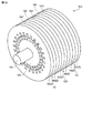
図11は、第3の実施形態に係る回転電機1100を概略的に示す斜視図であり、図12及び図13は、回転子130及び固定子140の概略構造を示す断面斜視図である。図13に示す断面は、図12に示す断面から極ピッチ分だけ傾いた断面である。さらに、図14(a)及び(b)並びに図15(a)及び(b)は、回転電機1100の部分断面図である。
(Third embodiment)
The basic configuration of the rotating electrical machine according to the third embodiment is the same as that of the rotating electrical machine according to the first embodiment, but the third embodiment is different from the first embodiment in the structure of the rotor. .
FIG. 11 is a perspective view schematically showing a rotating electrical machine 1100 according to the third embodiment, and FIGS. 12 and 13 are cross-sectional perspective views showing a schematic structure of the rotor 130 and the stator 140. The cross section shown in FIG. 13 is a cross section inclined by the pole pitch from the cross section shown in FIG. Further, FIGS. 14A and 14B and FIGS. 15A and 15B are partial cross-sectional views of the rotating electrical machine 1100.

図11に示される回転電機1100では、図12及び図13に示すように、回転子130は、環状の磁界発生部1231、磁界発生部1231の一端部から固定子140に向かって延びる複数の磁極1235Aと、磁界発生部1231の他端部から固定子140に向かって延びる複数の磁極1235Bと、を備える。磁界発生部1231は磁極1235A及び1235B間に介挿されている。複数の磁極1235Aは軸方向に複数の磁極1235Bにそれぞれ対向している。ある磁極1235Aは軸方向に対向している磁極1235Bと対を成す。磁極1235A及び対を成す磁極1235Bの一方は直線的に径方向に延び、他方は先端が回転子130と固定子140との対向面の中央部に対向するように曲がっている。磁界発生部1231は、例えば永久磁石であり、軸方向に磁束を発生する。磁界発生部1231で発生する磁束は界磁磁界として利用される。磁極1235A及び1235Bは強磁性体で形成される。第3の実施形態の回転子130は、第1の実施形態の回転子130において、環状部133の中央部に磁界発生部1231を設け、巻線132を除去したものに対応する。   In the rotating electrical machine 1100 shown in FIG. 11, as shown in FIGS. 12 and 13, the rotor 130 has an annular magnetic field generator 1231 and a plurality of magnetic poles extending from one end of the magnetic field generator 1231 toward the stator 140. 1235A and a plurality of magnetic poles 1235B extending from the other end of the magnetic field generator 1231 toward the stator 140. The magnetic field generator 1231 is interposed between the magnetic poles 1235A and 1235B. The plurality of magnetic poles 1235A are opposed to the plurality of magnetic poles 1235B in the axial direction. A certain magnetic pole 1235A is paired with a magnetic pole 1235B facing in the axial direction. One of the magnetic pole 1235 </ b> A and the pair of magnetic poles 1235 </ b> B linearly extends in the radial direction, and the other is bent so that the tip thereof is opposed to the central portion of the opposed surfaces of the rotor 130 and the stator 140. The magnetic field generator 1231 is a permanent magnet, for example, and generates a magnetic flux in the axial direction. The magnetic flux generated by the magnetic field generator 1231 is used as a field magnetic field. The magnetic poles 1235A and 1235B are formed of a ferromagnetic material. The rotor 130 of the third embodiment corresponds to the rotor 130 of the first embodiment in which the magnetic field generator 1231 is provided in the center of the annular portion 133 and the winding 132 is removed.

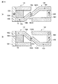
ある回転角度では、図14(a)に示すような回転子130の曲がった磁極1235Bと固定子140の曲がった磁極145Aが対向する部分と、図14(b)に示すような回転子130の曲がった磁極1235Aと固定子140の曲がった磁極145Bが対向する部分が隣り合って存在する。磁界発生部1231は、矢印1403に示される方向に磁界を発生し、それにより、磁気回路1402が形成される。磁気回路1402では、磁束は矢印1404で示される向きに流れる。具体的には、磁極1235B、空隙1411、磁極145A、環状部143、磁極145B、空隙1412、磁極1235A、磁界発生部1231、磁極1235Bの経路で磁束が流れる。磁気回路1402は、第1の実施形態のような巻線132の励磁により形成される磁気回路402(図4(a)及び(b))に相当する。第3の実施形態では、磁界発生部1231で発生する磁束と巻線142の励磁によって発生する磁束が相互作用し、その結果、トルクが発生する。   At a certain rotation angle, the bent magnetic pole 1235B of the rotor 130 as shown in FIG. 14A and the bent magnetic pole 145A of the stator 140 face each other, and the rotor 130 as shown in FIG. A portion where the bent magnetic pole 1235 </ b> A and the bent magnetic pole 145 </ b> B of the stator 140 are opposed to each other is adjacent. The magnetic field generator 1231 generates a magnetic field in the direction indicated by the arrow 1403, thereby forming a magnetic circuit 1402. In the magnetic circuit 1402, the magnetic flux flows in the direction indicated by the arrow 1404. Specifically, the magnetic flux flows through the path of the magnetic pole 1235B, the gap 1411, the magnetic pole 145A, the annular portion 143, the magnetic pole 145B, the gap 1412, the magnetic pole 1235A, the magnetic field generator 1231, and the magnetic pole 1235B. The magnetic circuit 1402 corresponds to the magnetic circuit 402 (FIGS. 4A and 4B) formed by exciting the winding 132 as in the first embodiment. In the third embodiment, the magnetic flux generated by the magnetic field generator 1231 interacts with the magnetic flux generated by excitation of the winding 142, and as a result, torque is generated.

他の回転角度では、図15(a)に示すように、回転子130の曲がった磁極1235Aと固定子140の曲がった磁極145Aが対向し、且つ、回転子130の直線状の磁極1235Bと固定子140の直線状の磁極145Bが対向する。図15(a)に示す部分と隣り合う部分では、図15(b)に示すように、直線状の磁極1235Aと直線状の磁極145Aが対向し、且つ、曲がった磁極1235Bと曲がった磁極145Bが対向する。   At other rotation angles, as shown in FIG. 15A, the bent magnetic pole 1235A of the rotor 130 and the bent magnetic pole 145A of the stator 140 face each other and are fixed to the linear magnetic pole 1235B of the rotor 130. The linear magnetic poles 145B of the child 140 are opposed to each other. In a portion adjacent to the portion shown in FIG. 15A, as shown in FIG. 15B, the linear magnetic pole 1235A and the linear magnetic pole 145A are opposed to each other, and the bent magnetic pole 1235B and the bent magnetic pole 145B are used. Opposite.

図15(a)に示す部分では、磁界発生部1231は、矢印1503に示される方向に磁界を発生し、それにより、磁気回路1502が形成される。磁気回路1502では、磁束は矢印1504で示される向きに流れる。具体的には、磁極1235B、空隙1511、磁極145B、環状部143、磁極145A、空隙1512、磁極1235A、磁界発生部1231の経路で磁束が流れる。磁気回路1502は、第1の実施形態のような巻線132の励磁により形成される磁気回路502(図5(a))に相当する。磁界発生部1231で発生する磁束と巻線142の励磁によって発生する磁束が相互作用し、その結果、トルクが発生する。   In the portion shown in FIG. 15A, the magnetic field generator 1231 generates a magnetic field in the direction indicated by the arrow 1503, thereby forming a magnetic circuit 1502. In the magnetic circuit 1502, the magnetic flux flows in the direction indicated by the arrow 1504. Specifically, the magnetic flux flows through the path of the magnetic pole 1235B, the air gap 1511, the magnetic pole 145B, the annular portion 143, the magnetic pole 145A, the air gap 1512, the magnetic pole 1235A, and the magnetic field generating portion 1231. The magnetic circuit 1502 corresponds to the magnetic circuit 502 (FIG. 5A) formed by exciting the winding 132 as in the first embodiment. The magnetic flux generated by the magnetic field generator 1231 interacts with the magnetic flux generated by the excitation of the winding 142, and as a result, torque is generated.

図15(b)に示す部分では、磁界発生部1231は、矢印1503に示される方向に磁界を発生し、それにより、磁気回路1505が形成される。磁気回路1505では、磁束は矢印1506で示される向きに流れる。具体的には、磁極1235B、空隙1513、磁極145B、環状部143、磁極145A、空隙1514、磁極1235A、磁界発生部1231の経路で磁束が流れる。磁気回路1505は、第1の実施形態のような巻線132の励磁により形成される磁気回路504(図5(b))に相当する。磁界発生部1231で発生する磁束と巻線142の励磁によって発生する磁束が相互作用し、その結果、トルクが発生する。   In the part shown in FIG. 15B, the magnetic field generator 1231 generates a magnetic field in the direction indicated by the arrow 1503, whereby a magnetic circuit 1505 is formed. In the magnetic circuit 1505, the magnetic flux flows in the direction indicated by the arrow 1506. Specifically, the magnetic flux flows through the path of the magnetic pole 1235B, the gap 1513, the magnetic pole 145B, the annular portion 143, the magnetic pole 145A, the gap 1514, the magnetic pole 1235A, and the magnetic field generator 1231. The magnetic circuit 1505 corresponds to the magnetic circuit 504 (FIG. 5B) formed by exciting the winding 132 as in the first embodiment. The magnetic flux generated by the magnetic field generator 1231 interacts with the magnetic flux generated by the excitation of the winding 142, and as a result, torque is generated.

本実施形態では、巻線142を励磁した場合には、回転電機1100のいずれの断面においても、図14(a)及び(b)に示した磁気回路1402、図15(a)に示した磁気回路1502、及び図15(b)に示した磁気回路1505のいずれかが形成される。その結果、高トルク化を実現することができる。   In this embodiment, when the winding 142 is excited, the magnetic circuit 1402 shown in FIGS. 14A and 14B and the magnetism shown in FIG. Either the circuit 1502 or the magnetic circuit 1505 shown in FIG. 15B is formed. As a result, high torque can be realized.

第3の実施形態に係る回転電機1100は、第1の実施形態と同様に高いトルクを発生することができる。さらに、回転子130に磁界発生部1231を設けることにより、回転子130に取り付ける巻線及びこの巻線に電源供給するためのスリップリングを設けなくてよくなる。そのため、スリップリングの磨耗などの保守作業が不要となり、長期間回転動作の信頼性が向上させることができる。また、スリップリングを設けない分、回転電機1100を小型にすることができる。   The rotating electrical machine 1100 according to the third embodiment can generate a high torque as in the first embodiment. Further, by providing the magnetic field generator 1231 in the rotor 130, it is not necessary to provide a winding attached to the rotor 130 and a slip ring for supplying power to this winding. Therefore, maintenance work such as wear of the slip ring becomes unnecessary, and the reliability of the rotation operation for a long time can be improved. Further, since the slip ring is not provided, the rotating electrical machine 1100 can be reduced in size.

(第4の実施形態)
第4の実施形態に係る回転電機の基本的な構成は、第1の実施形態に係る回転電機と同様であるが、第4の実施形態は、固定子の構造が第1の実施形態と異なる。
図16は、第4の実施形態に係る回転電機1600を概略的に示す斜視図であり、図17及び図18は、回転子130及び固定子140の概略構造を示す断面斜視図である。図17に示す断面は、図18に示す断面から極ピッチ分だけ傾いた断面である。さらに、図19(a)及び(b)並びに図20(a)及び(b)は、回転電機1600の部分断面図である。
(Fourth embodiment)
The basic configuration of the rotating electrical machine according to the fourth embodiment is the same as that of the rotating electrical machine according to the first embodiment, but the fourth embodiment is different from the first embodiment in the structure of the stator. .
FIG. 16 is a perspective view schematically showing a rotating electrical machine 1600 according to the fourth embodiment, and FIGS. 17 and 18 are cross-sectional perspective views showing a schematic structure of the rotor 130 and the stator 140. The cross section shown in FIG. 17 is a cross section inclined by the pole pitch from the cross section shown in FIG. Further, FIGS. 19A and 19B and FIGS. 20A and 20B are partial cross-sectional views of the rotating electrical machine 1600. FIG.

図16に示される回転電機1600では、図17及び図18に示すように、固定子140は、環状の磁界発生部1641、磁界発生部1641の一端部から回転子130に向かって延びる複数の磁極1642Aと、磁界発生部1641の他端部から回転子130に向かって延びる複数の磁極1642Bと、を備える。磁界発生部1641は磁極1642A及び1642B間に介挿されている。複数の磁極1642Aは軸方向に複数の磁極1642Bにそれぞれ対向している。ある磁極1642Aは軸方向に対向している磁極1642Bと対を成す。磁極1642A及び対を成す磁極1642Bの一方は直線的に径方向に延び、他方は先端が回転子130と固定子140との対向面の中央部に対向するように曲がっている。磁界発生部1641は、例えば永久磁石であり、軸方向に磁束を発生する。磁界発生部1641で発生する磁束は界磁磁界として利用される。磁極1235A及び1235Bは強磁性体で形成される。第4の実施形態の固定子140は、第1の実施形態の固定子140において、環状部143の中央部に磁界発生部1641を設け、巻線142を除去したものに対応する。   In the rotating electrical machine 1600 shown in FIG. 16, as shown in FIGS. 17 and 18, the stator 140 includes an annular magnetic field generator 1641 and a plurality of magnetic poles extending from one end of the magnetic field generator 1641 toward the rotor 130. 1642A, and a plurality of magnetic poles 1642B extending from the other end of the magnetic field generator 1641 toward the rotor 130. The magnetic field generator 1641 is interposed between the magnetic poles 1642A and 1642B. The plurality of magnetic poles 1642A are opposed to the plurality of magnetic poles 1642B in the axial direction. A certain magnetic pole 1642A is paired with a magnetic pole 1642B facing in the axial direction. One of the magnetic pole 1642A and the pair of magnetic poles 1642B linearly extends in the radial direction, and the other is bent so that the tip thereof is opposed to the central portion of the opposed surfaces of the rotor 130 and the stator 140. The magnetic field generator 1641 is a permanent magnet, for example, and generates a magnetic flux in the axial direction. The magnetic flux generated by the magnetic field generator 1641 is used as a field magnetic field. The magnetic poles 1235A and 1235B are formed of a ferromagnetic material. The stator 140 according to the fourth embodiment corresponds to the stator 140 according to the first embodiment in which the magnetic field generator 1641 is provided at the center of the annular portion 143 and the winding 142 is removed.

ある回転角度では、図19(a)に示すような回転子130の曲がった磁極135Bと固定子140の曲がった磁極1642Aが対向する部分と、図14(b)に示すような回転子130の曲がった磁極135Aと固定子140の曲がった磁極1642Bが対向する部分が隣り合って存在する。磁界発生部1641は、矢印1903で示される方向に磁界を発生し、それにより、磁気回路1902が形成される。磁気回路1902では、磁束は矢印1904で示される向きに流れる。具体的には、磁界発生部1641、磁極1642A、空隙1911、磁極135B、環状部133、磁極135A、空隙1912、磁極1642B、磁界発生部1641の経路で磁束が流れる。磁気回路1902は、第1の実施形態のような巻線142の励磁により形成される磁気回路402(図4(a)及び(b))に相当する。第3の実施形態では、磁界発生部1641で発生する磁束と巻線132の励磁によって発生する磁束が相互作用し、その結果、トルクが発生する。   At a certain rotation angle, the bent magnetic pole 135B of the rotor 130 as shown in FIG. 19A and the bent magnetic pole 1642A of the stator 140 face each other, and the rotor 130 as shown in FIG. A portion where the bent magnetic pole 135 </ b> A and the bent magnetic pole 1642 </ b> B of the stator 140 are opposed to each other is adjacent. The magnetic field generator 1641 generates a magnetic field in the direction indicated by the arrow 1903, thereby forming a magnetic circuit 1902. In the magnetic circuit 1902, the magnetic flux flows in the direction indicated by the arrow 1904. Specifically, the magnetic flux flows through the path of the magnetic field generator 1641, the magnetic pole 1642A, the air gap 1911, the magnetic pole 135B, the annular portion 133, the magnetic pole 135A, the air gap 1912, the magnetic pole 1642B, and the magnetic field generator 1641. The magnetic circuit 1902 corresponds to the magnetic circuit 402 (FIGS. 4A and 4B) formed by exciting the winding 142 as in the first embodiment. In the third embodiment, the magnetic flux generated by the magnetic field generator 1641 interacts with the magnetic flux generated by the excitation of the winding 132, and as a result, torque is generated.

他の回転角度では、図20(a)に示すように、回転子130の曲がった磁極135Aと固定子140の曲がった磁極1642Aが対向し、且つ、回転子130の直線状の磁極135Bと固定子140の直線状の磁極1642Bが対向する。図20(a)に示す部分と隣り合う部分では、図20(b)に示すように、直線状の磁極135Aと直線状の磁極1642Aが対向し、且つ、曲がった磁極135Bと曲がった磁極1642Bが対向する。   At other rotation angles, as shown in FIG. 20A, the bent magnetic pole 135A of the rotor 130 and the bent magnetic pole 1642A of the stator 140 face each other and are fixed to the linear magnetic pole 135B of the rotor 130. The linear magnetic pole 1642B of the child 140 opposes. In a portion adjacent to the portion shown in FIG. 20A, as shown in FIG. 20B, the linear magnetic pole 135A and the linear magnetic pole 1642A face each other, and the bent magnetic pole 135B and the bent magnetic pole 1642B are provided. Opposite.

図20(a)に示す部分では、磁界発生部1641は、矢印2003で示される方向に磁界を発生し、それにより、磁気回路2002が形成される。磁気回路2002では、磁束は矢印2004で示される向きに流れる。具体的には、磁極1642A、空隙2011、磁極135A、環状部133、磁極135B、空隙2012、磁極1642B、磁界発生部1641の経路で磁束が流れる。磁気回路2002は、第1の実施形態のような巻線142の励磁により形成される磁気回路502(図5(a))に相当する。磁界発生部1641で発生する磁束と巻線132の励磁によって発生する磁束が相互作用し、その結果、トルクが発生する。   In the portion shown in FIG. 20A, the magnetic field generator 1641 generates a magnetic field in the direction indicated by the arrow 2003, whereby the magnetic circuit 2002 is formed. In the magnetic circuit 2002, the magnetic flux flows in the direction indicated by the arrow 2004. Specifically, the magnetic flux flows through the path of the magnetic pole 1642A, the gap 2011, the magnetic pole 135A, the annular portion 133, the magnetic pole 135B, the gap 2012, the magnetic pole 1642B, and the magnetic field generator 1641. The magnetic circuit 2002 corresponds to the magnetic circuit 502 (FIG. 5A) formed by exciting the winding 142 as in the first embodiment. The magnetic flux generated by the magnetic field generator 1641 interacts with the magnetic flux generated by the excitation of the winding 132, and as a result, torque is generated.

図20(b)に示す部分では、磁界発生部1641は、矢印2003で示される方向に磁界を発生し、それにより、磁気回路2005が形成される。磁気回路2005では、磁束は矢印2006で示される向きに流れる。具体的には、磁極1642A、空隙2013、磁極135A、環状部133、磁極135B、空隙2014、磁極1642B、磁界発生部1641の経路で磁束が流れる。磁気回路2005は、第1の実施形態のような巻線142の励磁により形成される磁気回路504(図5(b))に相当する。磁界発生部1641で発生する磁束と巻線132の励磁によって発生する磁束が相互作用し、その結果、トルクが発生する。   In the part shown in FIG. 20B, the magnetic field generator 1641 generates a magnetic field in the direction indicated by the arrow 2003, whereby the magnetic circuit 2005 is formed. In the magnetic circuit 2005, the magnetic flux flows in the direction indicated by the arrow 2006. Specifically, the magnetic flux flows through the path of the magnetic pole 1642A, the air gap 2013, the magnetic pole 135A, the annular portion 133, the magnetic pole 135B, the air gap 2014, the magnetic pole 1642B, and the magnetic field generator 1641. The magnetic circuit 2005 corresponds to the magnetic circuit 504 (FIG. 5B) formed by exciting the winding 142 as in the first embodiment. The magnetic flux generated by the magnetic field generator 1641 interacts with the magnetic flux generated by the excitation of the winding 132, and as a result, torque is generated.

本実施形態では、巻線132を励磁した場合には、回転電機1600のいずれの断面においても、図19(a)及び(b)に示した磁気回路1902、図20(a)に示した磁気回路2002、及び図20(b)に示した磁気回路2005のいずれかが形成される。その結果、高トルク化を実現することができる。   In the present embodiment, when the winding 132 is excited, the magnetic circuit 1902 shown in FIGS. 19A and 19B and the magnetism shown in FIG. Either the circuit 2002 or the magnetic circuit 2005 shown in FIG. 20B is formed. As a result, high torque can be realized.

第4の実施形態に係る回転電機1600は、第1の実施形態と同様に高いトルクを発生することができる。さらに、固定子140に巻線を設けないので、固定子140の巻線への電源供給が不要となる。一般には、第3実施形態のように磁界発生部を回転子側に配置する方がスリップリングを不要とする点で好ましい。   The rotating electrical machine 1600 according to the fourth embodiment can generate a high torque as in the first embodiment. Further, since no winding is provided on the stator 140, it is not necessary to supply power to the winding of the stator 140. In general, it is preferable to dispose the magnetic field generator on the rotor side as in the third embodiment in that a slip ring is unnecessary.

(第5の実施形態)
第5の実施形態では、回転電機を駆動するシステムについて説明する。
(Fifth embodiment)
In the fifth embodiment, a system for driving a rotating electrical machine will be described.

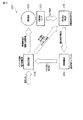
図21は、第5の実施形態に係る回転電機駆動系2100を概略的に示している。回転電機駆動系2100は、図21に示すように、回転電機2101、回転角度検出部2102、回転制御部2103、及び駆動回路部2104を備える。回転電機2101は、第1から第4の実施形態のいずれかの実施形態に係る回転電機であり得る。   FIG. 21 schematically shows a rotating electrical machine drive system 2100 according to the fifth embodiment. As shown in FIG. 21, the rotating electrical machine drive system 2100 includes a rotating electrical machine 2101, a rotation angle detection unit 2102, a rotation control unit 2103, and a drive circuit unit 2104. The rotating electrical machine 2101 can be a rotating electrical machine according to any one of the first to fourth embodiments.

回転角度検出部2102は、回転電機2101に含まれる回転子の回転軸周りの回転角度を検出する。一例では、回転角度検出部2102は、回転電機2101の回転軸に取り付けられた回転角度センサ2105の出力信号から回転角度を検出する。他の例では、回転角度検出部2102は、駆動回路部2104により出力される電圧及び電流と、回転電機2101の物理モデルと、を用いて回転角度を検出する。後者の検出方法をセンサレス推定と呼ぶ。   The rotation angle detection unit 2102 detects the rotation angle around the rotation axis of the rotor included in the rotating electrical machine 2101. In one example, the rotation angle detection unit 2102 detects the rotation angle from the output signal of the rotation angle sensor 2105 attached to the rotation shaft of the rotating electrical machine 2101. In another example, the rotation angle detection unit 2102 detects the rotation angle using the voltage and current output from the drive circuit unit 2104 and the physical model of the rotating electrical machine 2101. The latter detection method is called sensorless estimation.

回転制御部2103は、回転角度検出部2102から出力された回転角度情報(検出信号ともいう)に基づいて駆動回路部2104を制御する。具体的には、回転制御部2103は、回転角度情報と実装された回転制御アルゴリズムとに基づいて駆動回路部2104に印加すべき電圧を決定し、この電圧を駆動回路部2104に供給する。   The rotation control unit 2103 controls the drive circuit unit 2104 based on rotation angle information (also referred to as a detection signal) output from the rotation angle detection unit 2102. Specifically, the rotation control unit 2103 determines a voltage to be applied to the drive circuit unit 2104 based on the rotation angle information and the implemented rotation control algorithm, and supplies this voltage to the drive circuit unit 2104.

駆動回路部2104は、回転制御部2103からの電圧供給及び図示しない電源装置からの電源供給を受け、回転電機2101の電機子巻線及び界磁巻線に電流を供給する。例えば、回転電機2101が第1の実施形態で説明した回転電機100(図1)である場合、電機子巻線は回転子130の巻線132に対応し、界磁巻線は固定子140の巻線142に対応する。電流の供給により回転電機2101の回転子にトルクが加わり、回転電機2101が駆動される。   The drive circuit unit 2104 receives a voltage supply from the rotation control unit 2103 and a power supply from a power supply device (not shown), and supplies current to the armature winding and the field winding of the rotating electrical machine 2101. For example, when the rotating electrical machine 2101 is the rotating electrical machine 100 (FIG. 1) described in the first embodiment, the armature winding corresponds to the winding 132 of the rotor 130, and the field winding is the stator 140. Corresponding to the winding 142. Torque is applied to the rotor of the rotating electrical machine 2101 by supplying current, and the rotating electrical machine 2101 is driven.

図22は、駆動回路部2104の構成例を概略的に示している。図22に示される駆動回路部2104は、スイッチング回路2201、電力増幅回路2202、及びゲートドライブ回路2203を備える。スイッチング回路2201は、例えばIGBT(insulated gate bipolar transistor)及びダイオードなどを含む複数のスイッチング部2204を含む。スイッチング部2204は各相の電機子巻線2205にブリッジ接続されている。スイッチング部2204は、ゲートドライブ回路2203からのパルス信号により駆動される。さらに、各相の界磁巻線2206には、電力増幅回路2202から電源が供給される。図22では、回転電機2101は三相の回転電機(すなわち、図1に示されるような回転子と固定子を含む駆動要素を3つ含む回転電機)であり、電機子巻線は三相結線を想定している。   FIG. 22 schematically illustrates a configuration example of the drive circuit unit 2104. The drive circuit portion 2104 shown in FIG. 22 includes a switching circuit 2201, a power amplification circuit 2202, and a gate drive circuit 2203. The switching circuit 2201 includes a plurality of switching units 2204 including, for example, IGBTs (insulated gate bipolar transistors) and diodes. The switching unit 2204 is bridge-connected to the armature winding 2205 of each phase. The switching unit 2204 is driven by a pulse signal from the gate drive circuit 2203. Further, power is supplied from the power amplification circuit 2202 to the field winding 2206 of each phase. In FIG. 22, a rotating electrical machine 2101 is a three-phase rotating electrical machine (that is, a rotating electrical machine including three driving elements including a rotor and a stator as shown in FIG. 1), and the armature winding is a three-phase connection. Is assumed.

なお、回転電機2101の相数が異なる場合にも、同様にその相数に対応したスイッチング回路2201及び電力増幅回路2202を適用できる。また、電機子巻線2205に電力増幅回路2202を適用し、界磁巻線2206にスイッチング回路2201を適用してもよい。   Note that, even when the number of phases of the rotating electrical machine 2101 is different, the switching circuit 2201 and the power amplification circuit 2202 corresponding to the number of phases can be similarly applied. Further, the power amplification circuit 2202 may be applied to the armature winding 2205 and the switching circuit 2201 may be applied to the field winding 2206.

図23は、三相結線をした電機子巻線2205に流れる電流の一例を示す。図23では、スイッチング回路2201を用いたPWM(pulse width modulation)制御を適用した場合、或いは、電力増幅回路2202の出力を適用した場合における三相電流を示している。実際は三相電流にはノイズが含まれるが、図23には、位相が120度ずつ異なる基本波成分のみが示されている。この基本波の周波数に対応した速度で回転子は駆動される。   FIG. 23 shows an example of a current flowing through the armature winding 2205 having a three-phase connection. FIG. 23 shows three-phase currents when PWM (pulse width modulation) control using the switching circuit 2201 is applied, or when the output of the power amplifier circuit 2202 is applied. Actually, the three-phase current includes noise, but FIG. 23 shows only fundamental wave components whose phases are different by 120 degrees. The rotor is driven at a speed corresponding to the frequency of the fundamental wave.

図24は、三相結線をした電機子巻線2205に流れる電流の他の例を示す。図24では、スイッチング回路2201を用いたパルス制御を行い、それぞれ位相が120度異なる矩形波状の三相電流を供給している。   FIG. 24 shows another example of the current flowing through the armature winding 2205 having a three-phase connection. In FIG. 24, pulse control using the switching circuit 2201 is performed, and rectangular wave-shaped three-phase currents each having a phase difference of 120 degrees are supplied.

第5の実施形態に係る回転電機駆動系2100では、回転子の位置に対して適切な制御系が組まれているので、安定な回転動作が可能になる。さらに、回転角度検出部2102がセンサレス推定を行う場合、回転角度センサ2105が不要となり、コストが抑えられる。また、回転電機2101は相数を任意に設定でき、その相数に応じて、既存の同期モータのPWM制御や、既存のPM(permanent magnet)型又はハイブリッド型のステッピングモータと同様の制御を適用して駆動することが可能である。   In the rotating electrical machine drive system 2100 according to the fifth embodiment, since an appropriate control system is assembled with respect to the position of the rotor, a stable rotational operation is possible. Furthermore, when the rotation angle detection unit 2102 performs sensorless estimation, the rotation angle sensor 2105 is unnecessary, and the cost can be reduced. The rotating electrical machine 2101 can arbitrarily set the number of phases, and according to the number of phases, PWM control of an existing synchronous motor or control similar to an existing PM (permanent magnet) type or hybrid type stepping motor is applied. And can be driven.

(第6の実施形態)
第6の実施形態では、回転電機を備える車輌について説明する。この回転電機は、第1から第4の実施形態のいずれかの実施形態で説明した回転電機であり得る。第6の実施形態に係る車輌の例としては、二輪、三輪、又は四輪のハイブリッド自動車、二輪、三輪、又は四輪の電気自動車、電動アシスト自転車などが挙げられる。
(Sixth embodiment)
In the sixth embodiment, a vehicle including a rotating electrical machine will be described. This rotating electrical machine may be the rotating electrical machine described in any one of the first to fourth embodiments. Examples of the vehicle according to the sixth embodiment include a two-wheeled, three-wheeled, or four-wheeled hybrid vehicle, a two-wheeled, three-wheeled, or four-wheeled electric vehicle, an electrically assisted bicycle, and the like.

ハイブリッドタイプの車輌は、内燃機関と電池駆動の回転電機とを組み合わせて走行動力源とする。電気自動車は、電池駆動の回転電機を走行原動力とする。車輌の駆動力には、その走行条件に応じ、広範囲な回転数及びトルクの動力源が必要となる。一般的に内燃機関は理想的なエネルギー効率を示すトルク及び回転数が限られているため、それ以外の走行条件ではエネルギー効率が低下する。ハイブリッドタイプの車輌は、内燃機関を最適条件で稼動させて発電するとともに、高効率な回転電機で車輪を駆動することによって、或いは、内燃機関と回転電機の動力を合わせて車輪を駆動することによって、車輌全体のエネルギー効率を向上できる。また、減速時に車輌が持つ運動エネルギーを電力として回生することによって、通常の内燃機関単独走行の車輌と比較して、単位燃料当りの走行距離を飛躍的に増大させることができる。   A hybrid type vehicle uses a combination of an internal combustion engine and a battery-driven rotating electrical machine as a driving power source. An electric vehicle uses a battery-driven rotating electric machine as a driving force. The driving force of the vehicle requires a power source with a wide range of rotation speeds and torques depending on the running conditions. In general, since the internal combustion engine has a limited torque and rotational speed that show ideal energy efficiency, the energy efficiency decreases under other driving conditions. A hybrid type vehicle generates power by operating an internal combustion engine under optimum conditions, and by driving wheels with a high-efficiency rotating electrical machine, or by driving wheels by combining the power of the internal combustion engine and the rotating electrical machine. , Energy efficiency of the entire vehicle can be improved. Further, by regenerating the kinetic energy of the vehicle as electric power when decelerating, the travel distance per unit fuel can be dramatically increased as compared with a normal vehicle traveling alone.

ハイブリッド自動車は、内燃機関と回転電機の組み合わせ方によって大きく3つに分類することができる。
図25は、一般にシリーズハイブリッド自動車と呼ばれるハイブリッド自動車2500を概略的に示している。このハイブリッド自動車2500は、図25に示すように、内燃機関2501、発電機2502、インバータ2503、電源2504、回転電機2505、及び車輪2506を備える。回転電機2505は、例えば、第1の実施形態に係る回転電機100(図1)である。
Hybrid vehicles can be roughly classified into three types depending on the combination of the internal combustion engine and the rotating electric machine.
FIG. 25 schematically shows a hybrid vehicle 2500 generally called a series hybrid vehicle. As shown in FIG. 25, the hybrid vehicle 2500 includes an internal combustion engine 2501, a generator 2502, an inverter 2503, a power source 2504, a rotating electrical machine 2505, and wheels 2506. The rotating electrical machine 2505 is, for example, the rotating electrical machine 100 (FIG. 1) according to the first embodiment.

ハイブリッド自動車2500では、内燃機関2501で発生した動力は一旦全て発電機2502で電力に変換される。この電力はインバータ2503を通じて電源2504に蓄えられる。電源2504に蓄えられた電力は、インバータ2503を通じて回転電機2505に供給され、回転電機2505によって車輪2506が回転駆動される。このように、シリーズハイブリッド自動車は、電気自動車に発電機が複合されたようなシステムである。内燃機関は高効率な条件で運転でき、電力回生も可能である。その反面、車輪2506の駆動は回転電機2505によって行われるため、高出力な回転電機2505が必要となる。   In hybrid vehicle 2500, all the power generated in internal combustion engine 2501 is once converted into electric power by generator 2502. This electric power is stored in the power source 2504 through the inverter 2503. The electric power stored in the power source 2504 is supplied to the rotating electrical machine 2505 through the inverter 2503, and the wheel 2506 is rotationally driven by the rotating electrical machine 2505. As described above, the series hybrid vehicle is a system in which a generator is combined with an electric vehicle. The internal combustion engine can be operated under highly efficient conditions and can also regenerate power. On the other hand, since the driving of the wheel 2506 is performed by the rotating electrical machine 2505, a high-output rotating electrical machine 2505 is required.

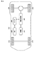
図26は、パラレルハイブリッド自動車と呼ばれるハイブリッド自動車2600を示している。このハイブリッド自動車2600は、図26に示すように、内燃機関2501、インバータ2503、電源2504、回転電機2601、及び車輪2506を備える。回転電機2601は、例えば第1の実施形態に係る回転電機100(図1)であり、車輪2506の駆動に使用されるとともに、発電機としても利用される。   FIG. 26 shows a hybrid vehicle 2600 called a parallel hybrid vehicle. As shown in FIG. 26, the hybrid vehicle 2600 includes an internal combustion engine 2501, an inverter 2503, a power source 2504, a rotating electrical machine 2601, and wheels 2506. The rotating electrical machine 2601 is, for example, the rotating electrical machine 100 (FIG. 1) according to the first embodiment, and is used for driving the wheels 2506 and also used as a generator.

ハイブリッド自動車2600では、車輪2506は主に内燃機関2501によって駆動される。内燃機関2501で発生した動力の一部は、場合によって回転電機2601で電力に変換される。この電力はインバータ2503を通じて電源2504に蓄えられる。負荷が重くなる発進や加速時には、電源2504からインバータ2503を通じて回転電機2601に電力を供給し、回転電機2601により駆動力を補助する。ハイブリッド自動車2600は、通常の自動車がベースになっており、内燃機関2501の負荷変動を少なくして高効率化を図り、電力回生なども合わせて行うシステムである。車輪2506の駆動は主に内燃機関2501によって行うため、回転電機2601の出力は、必要な補助の割合によって任意に決定することができる。比較的小さな回転電機2601及び電源2504を用いてシステムを構築することができる。   In hybrid vehicle 2600, wheels 2506 are mainly driven by internal combustion engine 2501. A part of the power generated in the internal combustion engine 2501 is converted into electric power by the rotating electrical machine 2601 as the case may be. This electric power is stored in the power source 2504 through the inverter 2503. When starting or accelerating with a heavy load, power is supplied from the power source 2504 to the rotating electrical machine 2601 through the inverter 2503, and the rotating electrical machine 2601 assists the driving force. The hybrid vehicle 2600 is a system based on a normal vehicle, which reduces the load fluctuation of the internal combustion engine 2501 to improve efficiency and also performs power regeneration. Since the driving of the wheel 2506 is mainly performed by the internal combustion engine 2501, the output of the rotating electrical machine 2601 can be arbitrarily determined depending on the necessary auxiliary ratio. A system can be constructed using a relatively small rotating electrical machine 2601 and a power source 2504.

図27は、シリーズ・パラレルハイブリッド自動車と呼ばれるハイブリッド自動車2700を示している。ハイブリッド自動車2700は、シリーズとパラレルの両方を組み合わせたシステムである。動力分割機構2701は、内燃機関2501の出力を発電用と車輪駆動用とに分割する。パラレル方式よりもきめ細かくエンジンの負荷制御を行い、エネルギー効率を高めることができる。   FIG. 27 shows a hybrid vehicle 2700 called a series / parallel hybrid vehicle. The hybrid vehicle 2700 is a system that combines both series and parallel. The power split mechanism 2701 splits the output of the internal combustion engine 2501 into power generation and wheel drive. The engine load can be controlled more finely than the parallel system, and energy efficiency can be improved.

図28は、第6の実施形態に係る電気自動車2800を概略的に示している。回転電機2601は、例えば第1の実施形態に係る回転電機100(図1)であり、車輪2506の駆動に使用されるとともに、発電機としても利用される。   FIG. 28 schematically shows an electric vehicle 2800 according to the sixth embodiment. The rotating electrical machine 2601 is, for example, the rotating electrical machine 100 (FIG. 1) according to the first embodiment, and is used for driving the wheels 2506 and also used as a generator.

電気自動車2800では、電源2504に蓄えられた電力は、インバータ2503を通じて回転電機2505に供給され、回転電機2505によって車輪2506が回転駆動される。回転電機2601は、車輪2506を駆動する一方で、場合により発電機として機能して電力を生成する。この電力により電源2504が充電される。   In the electric vehicle 2800, the electric power stored in the power source 2504 is supplied to the rotating electrical machine 2505 through the inverter 2503, and the wheel 2506 is rotationally driven by the rotating electrical machine 2505. The rotating electrical machine 2601 drives the wheels 2506, and in some cases functions as a generator to generate electric power. The power supply 2504 is charged by this power.

以上のように、第6の実施形態によれば、上述した実施形態に係る横方向磁束型回転電機を用いた車両が提供される。   As described above, according to the sixth embodiment, a vehicle using the transverse magnetic flux rotating electric machine according to the above-described embodiment is provided.

以上述べた少なくとも1つの実施形態に係る横方向磁束型回転電機では、いずれの断面でも磁気回路が形成されるように回転子及び固定子に磁極を設けることにより、磁束の漏れを低減でき、磁極面積を大きく確保することができる。その結果、高いトルクを発生することが可能になる。   In the transverse magnetic flux type rotating electrical machine according to at least one embodiment described above, magnetic flux leakage can be reduced by providing magnetic poles in the rotor and the stator so that a magnetic circuit is formed in any cross section. A large area can be secured. As a result, high torque can be generated.

なお、実施形態に係る回転電機は、図1、図6、図11、図16に示したような回転子と固定子との対向面の法線が半径方向となるラジアルギャップモータである例に限らず、回転子と固定子との対向面の法線が軸方向となるアキシャルギャップモータであってもよい。さらに、実施形態に係る回転電機は、図1、図6、図11、図16に示したような回転子が固定子の内側に位置するインナーロータである例に限らず、回転子が固定子の外側に位置するアウターロータであってもよい。   In addition, the rotary electric machine which concerns on embodiment is an example which is a radial gap motor from which the normal line of the opposing surface of a rotor and a stator becomes radial direction as shown in FIG.1, FIG.6, FIG.11 and FIG. Not limited to this, an axial gap motor in which the normal line of the opposed surfaces of the rotor and the stator is in the axial direction may be used. Furthermore, the rotating electrical machine according to the embodiment is not limited to the example in which the rotor is an inner rotor positioned inside the stator as shown in FIGS. 1, 6, 11, and 16, and the rotor is the stator. It may be an outer rotor located on the outside.

本発明のいくつかの実施形態を説明したが、これらの実施形態は、例として提示したものであり、発明の範囲を限定することは意図していない。これら新規な実施形態は、その他の様々な形態で実施されることが可能であり、発明の要旨を逸脱しない範囲で、種々の省略、置き換え、変更を行うことができる。これら実施形態やその変形は、発明の範囲や要旨に含まれるとともに、特許請求の範囲に記載された発明とその均等の範囲に含まれる。   Although several embodiments of the present invention have been described, these embodiments are presented by way of example and are not intended to limit the scope of the invention. These novel embodiments can be implemented in various other forms, and various omissions, replacements, and changes can be made without departing from the scope of the invention. These embodiments and modifications thereof are included in the scope and gist of the invention, and are included in the invention described in the claims and the equivalents thereof.

100…横方向磁束型回転電機、110…回転軸、120…駆動要素、130…回転子、131…強磁性体、132…巻線、133…環状部、135A,135B…磁極、140…固定子、141…強磁性体、142…巻線、143…環状部、145A,145B…磁極、150…連結部材、600…横方向磁束型回転電機、601…連結部材、731,732,734…強磁性体、733…非磁性体、1100…横方向磁束型回転電機、1231…磁界発生部、1235A,1235B…磁極、1600…横方向磁束型回転電機、1641…磁界発生部、1642A,1642B…磁極、2100…回転電機駆動系、2101…回転電機、2102…回転角度検出部、2103…回転制御部、2104…駆動回路部、2105…回転角度センサ、2201…スイッチング回路、2202…電力増幅回路、2203…ゲートドライブ回路、2204…スイッチング部、2205…電機子巻線、2206…界磁巻線、2500,2600、2700…ハイブリッド自動車、2501…内燃機関、2502…発電機、2503…インバータ、2504…電源、2505…回転電機、2506…車輪、2701…動力分割機構、2800…電気自動車。 DESCRIPTION OF SYMBOLS 100 ... Transverse magnetic flux type rotary electric machine, 110 ... Rotating shaft, 120 ... Drive element, 130 ... Rotor, 131 ... Ferromagnetic material, 132 ... Winding, 133 ... Annular part, 135A, 135B ... Magnetic pole, 140 ... Stator , 141 ... ferromagnetic material, 142 ... winding, 143 ... annular part, 145A, 145B ... magnetic pole, 150 ... connecting member, 600 ... transverse magnetic flux type rotating electrical machine, 601 ... connecting member, 731, 732, 734 ... ferromagnetic Body, 733 ... non-magnetic body, 1100 ... transverse magnetic flux rotating electric machine, 1231 ... magnetic field generator, 1235A, 1235B ... magnetic pole, 1600 ... transverse magnetic flux rotating electric machine, 1641 ... magnetic field generator, 1642A, 1642B ... magnetic pole, 2100: Rotating electrical machine drive system, 2101 ... Rotating electrical machine, 2102 ... Rotation angle detection unit, 2103 ... Rotation control unit, 2104 ... Drive circuit unit, 2105 ... Rotation angle sensor 2201, switching circuit, 2202 ... power amplifier circuit, 2203 ... gate drive circuit, 2204 ... switching unit, 2205 ... armature winding, 2206 ... field winding, 2500, 2600, 2700 ... hybrid vehicle, 2501 ... internal combustion Engine, 2502 ... Generator, 2503 ... Inverter, 2504 ... Power source, 2505 ... Electric rotating machine, 2506 ... Wheel, 2701 ... Power split mechanism, 2800 ... Electric vehicle.

図16に示される回転電機1600では、図17及び図18に示すように、固定子140は、環状の磁界発生部1641、磁界発生部1641の一端部から回転子130に向かって延びる複数の磁極1642Aと、磁界発生部1641の他端部から回転子130に向かって延びる複数の磁極1642Bと、を備える。磁界発生部1641は磁極1642A及び1642B間に介挿されている。複数の磁極1642Aは軸方向に複数の磁極1642Bにそれぞれ対向している。ある磁極1642Aは軸方向に対向している磁極1642Bと対を成す。磁極1642A及び対を成す磁極1642Bの一方は直線的に径方向に延び、他方は先端が回転子130と固定子140との対向面の中央部に対向するように曲がっている。磁界発生部1641は、例えば永久磁石であり、軸方向に磁束を発生する。磁界発生部1641で発生する磁束は界磁磁界として利用される。磁極1642A及び1642Bは強磁性体で形成される。第4の実施形態の固定子140は、第1の実施形態の固定子140において、環状部143の中央部に磁界発生部1641を設け、巻線142を除去したものに対応する。
In the rotating electrical machine 1600 shown in FIG. 16, as shown in FIGS. 17 and 18, the stator 140 includes an annular magnetic field generator 1641 and a plurality of magnetic poles extending from one end of the magnetic field generator 1641 toward the rotor 130. 1642A, and a plurality of magnetic poles 1642B extending from the other end of the magnetic field generator 1641 toward the rotor 130. The magnetic field generator 1641 is interposed between the magnetic poles 1642A and 1642B. The plurality of magnetic poles 1642A are opposed to the plurality of magnetic poles 1642B in the axial direction. A certain magnetic pole 1642A is paired with a magnetic pole 1642B facing in the axial direction. One of the magnetic pole 1642A and the pair of magnetic poles 1642B linearly extends in the radial direction, and the other is bent so that the tip thereof is opposed to the central portion of the opposed surfaces of the rotor 130 and the stator 140. The magnetic field generator 1641 is a permanent magnet, for example, and generates a magnetic flux in the axial direction. The magnetic flux generated by the magnetic field generator 1641 is used as a field magnetic field. The magnetic poles 1642A and 1642B are formed of a ferromagnetic material. The stator 140 according to the fourth embodiment corresponds to the stator 140 according to the first embodiment in which the magnetic field generator 1641 is provided at the center of the annular portion 143 and the winding 142 is removed.

Claims (7)

回転軸周りに回転可能な回転子であって、回転方向に巻かれた第1の巻線と、前記第1の巻線を取り囲む第1の強磁性体と、を備える回転子と、
前記回転子に対向して設けられた固定子であって、前記回転方向に巻かれた第2の巻線と、前記第2の巻線を取り囲む第2の強磁性体と、を備える固定子と、
を具備し、
前記第1の強磁性体は、第1の環状部と、前記第1の環状部の一端部から前記固定子に向かって延びる複数の第1の磁極と、前記第1の環状部の他端部から前記固定子に向かって延びる複数の第2の磁極と、を備え、第1の磁極と該第1の磁極に対向する第2の磁極の一方は、先端が前記固定子と前記回転子との対向面の中央部に対向するように形成され、
前記第2の強磁性体は、第2の環状部と、前記第2の環状部の一端部から前記回転子に向かって延びる複数の第3の磁極と、前記第2の環状部の他端部から前記回転子に向かって延びる複数の第4の磁極と、を備え、第3の磁極と該第3の磁極に対向する第4の磁極との一方は、先端が前記対向面の中央部に対向するように形成されている、横方向磁束型回転電機。
A rotor rotatable around a rotation axis, the rotor comprising: a first winding wound in a rotation direction; and a first ferromagnetic body surrounding the first winding;
A stator provided opposite to the rotor, the stator comprising: a second winding wound in the rotation direction; and a second ferromagnetic body surrounding the second winding. When,
Comprising
The first ferromagnetic body includes a first annular portion, a plurality of first magnetic poles extending from one end of the first annular portion toward the stator, and the other end of the first annular portion. A plurality of second magnetic poles extending from the portion toward the stator, wherein one of the first magnetic pole and the second magnetic pole facing the first magnetic pole has a tip at the stator and the rotor Is formed so as to face the center of the facing surface,
The second ferromagnetic body includes a second annular portion, a plurality of third magnetic poles extending from one end portion of the second annular portion toward the rotor, and the other end of the second annular portion. A plurality of fourth magnetic poles extending from the portion toward the rotor, and one of the third magnetic pole and the fourth magnetic pole facing the third magnetic pole has a tip at the center of the facing surface A transverse magnetic flux type rotating electrical machine that is formed so as to be opposed to the motor.
回転軸周りに回転可能な回転子であって、第1の強磁性体と、第2の強磁性体と、前記第1の強磁性体と前記第2の強磁性体を結合する第1の非磁性体と、を備える回転子と、
回転方向に巻かれた第1の巻線と、
前記第1の巻線が取り付けられた第3の強磁性体と、
前記回転子に対向して設けられた固定子であって、前記回転方向に巻かれた第2の巻線と、前記第2の巻線を取り囲む第4の強磁性体と、を備える固定子と、
前記第3の強磁性体を前記固定子に固定する第2の非磁性体と、
を具備し、
前記第1の巻線は、前記第1の強磁性体、前記第1の非磁性体、及び前記第3の強磁性体に囲まれる空間に配置され、
前記第1の強磁性体は、第1の環状部と、前記第1の環状部の一端部から前記固定子に向かって延びる複数の第1の磁極と、を備え、前記第2の強磁性体は、前記固定子に向かって延びる複数の第2の磁極を備え、第1の磁極と該第1の磁極に対向する第2の磁極の一方は、先端が前記固定子と前記回転子との対向面の中央部に対向するように形成され、
前記第4の強磁性体は、第2の環状部と、前記第2の環状部の一端部から前記回転子に向かって延びる複数の第3の磁極と、前記第2の環状部の他端部から前記回転子に向かって延びる複数の第4の磁極と、を備え、第3の磁極と該第3の磁極に対向する第4の磁極との一方は、先端が前記対向面の中央部に対向するように形成されている、横方向磁束型回転電機。
A rotor that is rotatable about a rotation axis, the first ferromagnet, the second ferromagnet, and the first ferromagnet that couples the first ferromagnet and the second ferromagnet. A rotor comprising a non-magnetic material,
A first winding wound in the direction of rotation;
A third ferromagnetic body to which the first winding is attached;
A stator provided opposite to the rotor, the stator comprising: a second winding wound in the rotation direction; and a fourth ferromagnetic body surrounding the second winding. When,
A second non-magnetic material for fixing the third ferromagnetic material to the stator;
Comprising
The first winding is disposed in a space surrounded by the first ferromagnetic body, the first non-magnetic body, and the third ferromagnetic body,
The first ferromagnetic body includes a first annular portion and a plurality of first magnetic poles extending from one end of the first annular portion toward the stator, and the second ferromagnetic member. The body includes a plurality of second magnetic poles extending toward the stator, and one of the first magnetic pole and the second magnetic pole facing the first magnetic pole has a tip at the stator and the rotor. Formed so as to face the center of the facing surface of
The fourth ferromagnetic body includes a second annular portion, a plurality of third magnetic poles extending from one end portion of the second annular portion toward the rotor, and the other end of the second annular portion. A plurality of fourth magnetic poles extending from the portion toward the rotor, and one of the third magnetic pole and the fourth magnetic pole facing the third magnetic pole has a tip at the center of the facing surface A transverse magnetic flux type rotating electrical machine that is formed so as to be opposed to the motor.
回転軸周りに回転可能な回転子であって、磁界を発生する環状の磁界発生部と、前記磁界発生部の一端部から前記固定子に向かって延びる複数の第1の磁極と、前記磁界発生部の他端部から前記固定子に向かって延びる複数の第2の磁極と、を備える回転子と、
前記回転子に対向して設けられた固定子であって、回転方向に巻かれた巻線と、前記巻線を取り囲む強磁性体と、を備える固定子と、
を具備し、
第1の磁極と該第1の磁極に対向する第2の磁極との一方は、先端が前記固定子と前記回転子との対向面の中央部に対向するように形成され、
前記強磁性体は、環状部と、前記環状部の一端部から前記回転子に向かって延びる複数の第3の磁極と、前記環状部の他端部から前記回転子に向かって延びる複数の第4の磁極と、を備え、第3の磁極と該第3の磁極に対向する第4の磁極との一方は、先端が前記対向面の中央部に対向するように形成されている、横方向磁束型回転電機。
An annular magnetic field generator that generates a magnetic field, a plurality of first magnetic poles extending from one end of the magnetic field generator toward the stator, and the magnetic field generation A plurality of second magnetic poles extending from the other end of the portion toward the stator, and a rotor,
A stator provided opposite to the rotor, the stator comprising: a winding wound in a rotation direction; and a ferromagnetic body surrounding the winding;
Comprising
One of the first magnetic pole and the second magnetic pole facing the first magnetic pole is formed so that the tip faces the center of the opposing surface of the stator and the rotor,
The ferromagnetic body includes an annular portion, a plurality of third magnetic poles extending from one end of the annular portion toward the rotor, and a plurality of first magnetic poles extending from the other end of the annular portion toward the rotor. Four magnetic poles, and one of the third magnetic pole and the fourth magnetic pole facing the third magnetic pole is formed such that the tip is opposed to the central portion of the facing surface. Magnetic flux type rotating electrical machine.
回転軸周りに回転可能な回転子であって、回転方向に巻かれた巻線と、前記巻線を取り囲む強磁性体と、を備え、前記強磁性体は、環状部と、前記環状部の一端部から前記固定子に向かって延びる複数の第1の磁極と、前記環状部の他端部から前記固定子に向かって延びる複数の第2の磁極と、を備える、回転子と、
前記回転子に対向して設けられた固定子であって、磁界を発生する環状の磁界発生部と、前記磁界発生部の一端部から前記固定子に向かって延びる複数の第3の磁極と、前記磁界発生部の他端部から前記固定子に向かって延びる複数の第4の磁極と、を備える固定子と、
を具備し、
第1の磁極と該第1の磁極に対向する第2の磁極との一方は、先端が前記固定子と前記回転子との対向面の中央部に対向するように形成され、
第3の磁極と該第3の磁極に対向する第4の磁極との一方は、先端が前記対向面の中央部に対向するように形成されている、横方向磁束型回転電機。
A rotor rotatable around a rotation axis, comprising: a winding wound in a rotation direction; and a ferromagnetic body surrounding the winding, wherein the ferromagnetic body includes an annular portion, and an annular portion of the annular portion. A rotor comprising a plurality of first magnetic poles extending from one end portion toward the stator and a plurality of second magnetic poles extending from the other end portion of the annular portion toward the stator;
A stator provided to face the rotor, and an annular magnetic field generator that generates a magnetic field, and a plurality of third magnetic poles extending from one end of the magnetic field generator toward the stator, A plurality of fourth magnetic poles extending from the other end of the magnetic field generation unit toward the stator, and a stator,
Comprising
One of the first magnetic pole and the second magnetic pole facing the first magnetic pole is formed so that the tip faces the center of the opposing surface of the stator and the rotor,
One of the third magnetic pole and the fourth magnetic pole facing the third magnetic pole is a transverse magnetic flux rotating electrical machine in which the tip is formed to face the central portion of the facing surface.
前記回転子の前記回転軸周りの回転角度を検出して検出信号を生成する検出部と、
前記第1の巻線及び第2の巻線に電流を供給する駆動回路部と、
前記検出信号に基づいて前記駆動回路部を制御する回転制御部と、
をさらに具備する請求項1又は2に記載の横方向磁束型回転電機。
A detection unit that detects a rotation angle of the rotor around the rotation axis and generates a detection signal;
A drive circuit section for supplying current to the first winding and the second winding;
A rotation control unit for controlling the drive circuit unit based on the detection signal;
The transverse magnetic flux type rotating electrical machine according to claim 1, further comprising:
前記回転子の前記回転軸周りの回転角度を検出して検出信号を生成する検出部と、
前記巻線に電流を供給する駆動回路部と、
前記検出信号に基づいて前記駆動回路部を制御する回転制御部と、
をさらに具備する請求項3又は4に記載の横方向磁束型回転電機。
A detection unit that detects a rotation angle of the rotor around the rotation axis and generates a detection signal;
A drive circuit section for supplying current to the winding;
A rotation control unit for controlling the drive circuit unit based on the detection signal;
The transverse magnetic flux type rotating electrical machine according to claim 3 or 4, further comprising:
請求項1乃至6のいずれか一項に記載の横方向磁束型回転電機を具備する車輌。   A vehicle comprising the transverse magnetic flux rotating electric machine according to any one of claims 1 to 6.
JP2013144729A 2013-07-10 2013-07-10 Transverse magnetic flux type rotating electric machine and vehicle Active JP6081304B2 (en)

Priority Applications (3)

Application Number Priority Date Filing Date Title
JP2013144729A JP6081304B2 (en) 2013-07-10 2013-07-10 Transverse magnetic flux type rotating electric machine and vehicle
US14/328,135 US9787144B2 (en) 2013-07-10 2014-07-10 Rotating electrical motor using transverse magnetic flux
CN201410326867.6A CN104283339A (en) 2013-07-10 2014-07-10 Transverse Magnetic Flux Rotating Electrical Machine and Vehicle

Applications Claiming Priority (1)

Application Number Priority Date Filing Date Title
JP2013144729A JP6081304B2 (en) 2013-07-10 2013-07-10 Transverse magnetic flux type rotating electric machine and vehicle

Publications (2)

Publication Number Publication Date
JP2015019496A true JP2015019496A (en) 2015-01-29
JP6081304B2 JP6081304B2 (en) 2017-02-15

Family

ID=52257941

Family Applications (1)

Application Number Title Priority Date Filing Date
JP2013144729A Active JP6081304B2 (en) 2013-07-10 2013-07-10 Transverse magnetic flux type rotating electric machine and vehicle

Country Status (3)

Country Link
US (1) US9787144B2 (en)
JP (1) JP6081304B2 (en)
CN (1) CN104283339A (en)

Cited By (1)

* Cited by examiner, † Cited by third party
Publication number Priority date Publication date Assignee Title
US10027189B2 (en) 2014-05-30 2018-07-17 Kabushiki Kaisha Toshiba Electric rotating machine

Families Citing this family (6)

* Cited by examiner, † Cited by third party
Publication number Priority date Publication date Assignee Title
JP6552929B2 (en) * 2015-09-16 2019-07-31 株式会社東芝 Electric rotating machine and elevator
WO2018035627A1 (en) * 2016-08-26 2018-03-01 琪盛实业有限公司 Stator combined structure of electric motor
JP6649238B2 (en) * 2016-12-13 2020-02-19 株式会社東芝 Rotating electric machines and robot devices
US11081934B2 (en) * 2019-10-30 2021-08-03 Maxwell Motors, Inc. Fin-cooled axial flux rotating electrical machine, and applications thereof
FR3106449B1 (en) * 2020-01-22 2022-05-06 Safran Electrical & Power Stator permanent magnet transverse flux electric machine
CN114079327B (en) * 2020-07-31 2023-02-14 山东精创磁电产业技术研究院有限公司 Transverse magnetic flux outer rotor motor

Citations (7)

* Cited by examiner, † Cited by third party
Publication number Priority date Publication date Assignee Title
JPS5752358A (en) * 1980-09-16 1982-03-27 Hitachi Ltd Rotor of brushless generator
JPH0348341U (en) * 1989-09-18 1991-05-09
JP2003533162A (en) * 2000-05-05 2003-11-05 ローベルト ボツシユ ゲゼルシヤフト ミツト ベシユレンクテル ハフツング Single-pole transverse flux machine
JP2008148397A (en) * 2006-12-07 2008-06-26 Hitachi Ltd Rotary electric machine
WO2008090853A1 (en) * 2007-01-22 2008-07-31 Tokyo University Of Science Educational Foundation Administrative Organization Rotating electric machine
JP4709846B2 (en) * 2005-10-07 2011-06-29 株式会社日立製作所 Rotating electric machine and in-vehicle rotating electric machine system
JP2012217312A (en) * 2011-03-30 2012-11-08 Toshiba Corp Transverse flux type rotary electric machine and vehicle

Family Cites Families (10)

* Cited by examiner, † Cited by third party
Publication number Priority date Publication date Assignee Title
FR2664105B1 (en) * 1990-07-02 1995-06-09 Radio Energie ROTARY STEPPER MOTOR WITH VARIABLE RELUCTANCE WITH TRANSVERSE FLOW.
GB9516497D0 (en) 1995-08-11 1995-10-11 Rolls Royce Power Eng Electrical machine
DE19642784A1 (en) 1996-10-17 1998-04-23 Bosch Gmbh Robert Claw pole generator
DE19714895C2 (en) 1997-04-03 2002-06-27 Daimlerchrysler Rail Systems Single-sided transverse flux machine in multi-strand design
DE10140303A1 (en) 2001-08-16 2003-02-27 Bosch Gmbh Robert Unipolar transversal flux machine has rotor module provided by rotor rings with outer teeth fitted around permanent magnet rings magnetized radially in opposite directions
KR100454656B1 (en) 2002-05-24 2004-11-05 한국전기연구원 Horizontal And Vertical Transportation System By Using Transverse Flux Linear Motor With Permanent Magnet Excitation
JP4109639B2 (en) 2004-02-17 2008-07-02 三菱電機株式会社 Rotating electrical machine rotor
JP5096705B2 (en) 2006-07-24 2012-12-12 株式会社日立産機システム Crotice type synchronous machine
JP4604064B2 (en) * 2007-06-19 2010-12-22 日立オートモティブシステムズ株式会社 Vehicle alternator and rotating electrical machine
CN102545519B (en) 2011-03-30 2016-02-03 戴珊珊 Reluctance motor for alternating-current continuous torque permanent magnet switch and excited control method thereof

Patent Citations (7)

* Cited by examiner, † Cited by third party
Publication number Priority date Publication date Assignee Title
JPS5752358A (en) * 1980-09-16 1982-03-27 Hitachi Ltd Rotor of brushless generator
JPH0348341U (en) * 1989-09-18 1991-05-09
JP2003533162A (en) * 2000-05-05 2003-11-05 ローベルト ボツシユ ゲゼルシヤフト ミツト ベシユレンクテル ハフツング Single-pole transverse flux machine
JP4709846B2 (en) * 2005-10-07 2011-06-29 株式会社日立製作所 Rotating electric machine and in-vehicle rotating electric machine system
JP2008148397A (en) * 2006-12-07 2008-06-26 Hitachi Ltd Rotary electric machine
WO2008090853A1 (en) * 2007-01-22 2008-07-31 Tokyo University Of Science Educational Foundation Administrative Organization Rotating electric machine
JP2012217312A (en) * 2011-03-30 2012-11-08 Toshiba Corp Transverse flux type rotary electric machine and vehicle

Cited By (1)

* Cited by examiner, † Cited by third party
Publication number Priority date Publication date Assignee Title
US10027189B2 (en) 2014-05-30 2018-07-17 Kabushiki Kaisha Toshiba Electric rotating machine

Also Published As

Publication number Publication date
US20150015126A1 (en) 2015-01-15
US9787144B2 (en) 2017-10-10
JP6081304B2 (en) 2017-02-15
CN104283339A (en) 2015-01-14

Similar Documents

Publication Publication Date Title
JP6081304B2 (en) Transverse magnetic flux type rotating electric machine and vehicle
JP4707696B2 (en) Axial gap type motor
JP6158022B2 (en) Rotating electric machine and vehicle
JP5592848B2 (en) Transverse magnetic flux type rotating electric machine and vehicle
JP5723524B2 (en) Rotating electric machines and electric vehicles
Rasmussen et al. Motor integrated permanent magnet gear with a wide torque-speed range
WO2013161474A1 (en) Permanent magnet rotating electrical machine and a motor vehicle using same
US9438151B2 (en) Transverse flux machine and vehicle
JP6446932B2 (en) Rotating electric machine
US20120038236A1 (en) Permanent Magnet Rotating Electric Machine and Electric Car Using the Same
WO2011046070A1 (en) Variable-flux dynamo-electric system
WO2010044426A1 (en) Rotating electric machine and electric automobile
JP2010233438A (en) Rotary electric machine system having axial direction gap structure with variable magnetic flux
JP4337989B1 (en) Magnetic excitation variable magnetic rotating machine system with magnet excitation
JP2016063572A (en) Rotary electric machine
JP5921244B2 (en) Permanent magnet type rotating electric machine
JP2012070608A (en) Magnet-excited rotary electric machine system
JP5914618B2 (en) Rotating electric machines and electric vehicles
WO2014188757A1 (en) Rotor for rotating electric machine, rotating electric machine, electric drive system, and electric vehicle
JP2013236412A (en) Transverse flux mechanical apparatus
JP3661634B2 (en) Double-sided gap type rotating electric machine
JP5650276B2 (en) Rotor and rotating electric machine equipped with the same
JP2007209197A (en) Ipm motor
JP5114135B2 (en) Axial gap type motor
JP2013013304A (en) Transverse magnetic flux machine

Legal Events

Date Code Title Description
A621 Written request for application examination

Free format text: JAPANESE INTERMEDIATE CODE: A621

Effective date: 20160316

TRDD Decision of grant or rejection written
A01 Written decision to grant a patent or to grant a registration (utility model)

Free format text: JAPANESE INTERMEDIATE CODE: A01

Effective date: 20161220

A977 Report on retrieval

Free format text: JAPANESE INTERMEDIATE CODE: A971007

Effective date: 20161221

A61 First payment of annual fees (during grant procedure)

Free format text: JAPANESE INTERMEDIATE CODE: A61

Effective date: 20170118

R151 Written notification of patent or utility model registration

Ref document number: 6081304

Country of ref document: JP

Free format text: JAPANESE INTERMEDIATE CODE: R151