JP2015018277A - Key drive device and keyboard instrument - Google Patents

Key drive device and keyboard instrument Download PDF

Info

Publication number
JP2015018277A
JP2015018277A JP2014193704A JP2014193704A JP2015018277A JP 2015018277 A JP2015018277 A JP 2015018277A JP 2014193704 A JP2014193704 A JP 2014193704A JP 2014193704 A JP2014193704 A JP 2014193704A JP 2015018277 A JP2015018277 A JP 2015018277A
Authority
JP
Japan
Prior art keywords
key
drive unit
solenoid
driving device
housing portion
Prior art date
Legal status (The legal status is an assumption and is not a legal conclusion. Google has not performed a legal analysis and makes no representation as to the accuracy of the status listed.)
Granted
Application number
JP2014193704A
Other languages
Japanese (ja)
Other versions
JP5958514B2 (en
Inventor
浩之 村上
Hiroyuki Murakami
浩之 村上
Current Assignee (The listed assignees may be inaccurate. Google has not performed a legal analysis and makes no representation or warranty as to the accuracy of the list.)
Yamaha Corp
Original Assignee
Yamaha Corp
Priority date (The priority date is an assumption and is not a legal conclusion. Google has not performed a legal analysis and makes no representation as to the accuracy of the date listed.)
Filing date
Publication date
Application filed by Yamaha Corp filed Critical Yamaha Corp
Priority to JP2014193704A priority Critical patent/JP5958514B2/en
Publication of JP2015018277A publication Critical patent/JP2015018277A/en
Application granted granted Critical
Publication of JP5958514B2 publication Critical patent/JP5958514B2/en
Active legal-status Critical Current
Anticipated expiration legal-status Critical

Links

Images

Landscapes

  • Electrophonic Musical Instruments (AREA)

Abstract

PROBLEM TO BE SOLVED: To fit, to a keyboard instrument part of whose keyboard is positioned above a leg beam, a key drive device for driving the keys without cutting and removing part of the leg beam.SOLUTION: A key drive device 10 is split into two drive units 10-L and 10-U; when a grand piano is to be fitted with the key drive device 10, in each of the drive units 10-L and 10-U, a solenoid housing 100b is inserted into a space 30b above a leg beam 4 configured in conjunction with a shelf plate 3; on the other hand, a solenoid housing 100a having in its lower part a substrate housing 200a in which a substrate for controlling actions of solenoids is inserted into a space 30a, different from the space 30b configured on the shelf plate 3.

Description

本発明は、鍵盤楽器の鍵を駆動させる鍵駆動装置の技術に関する。   The present invention relates to a technique of a key driving device that drives a key of a keyboard instrument.

アコースティックピアノに自動演奏機能をもたせるために、鍵の下方に存在する棚板を削って空間を作り、鍵を駆動させるソレノイドを有する鍵駆動装置(キードライブユニット)を、その空間に取り付けることが行われている。この鍵駆動装置は、演奏内容に応じた制御信号によりソレノイドを動作させて、各鍵の後端部(バックチェック側)付近において、鍵の下面側から駆動力を伝達する。これにより、あたかも演奏者によって押下されたかのように鍵が駆動され、ハンマによる打弦が行われて音が発生する。
このような鍵駆動装置は、その取り付け位置の関係から、アコースティックピアノに対する大掛かりな加工が必要であり、取り付け時間もかかっていた。そのため、鍵駆動装置のアコースティックピアノに対する取り付け処理を容易にする技術が開発されている(例えば、特許文献1)。
In order to give an acoustic piano an automatic performance function, a space is created by scraping the shelf under the key, and a key drive device (key drive unit) having a solenoid for driving the key is attached to the space. ing. This key driving device operates a solenoid by a control signal according to the performance contents, and transmits a driving force from the lower surface side of the key near the rear end portion (back check side) of each key. As a result, the key is driven as if it was pressed by the performer, and a hammer hits the string to generate a sound.
Such a key drive device requires a large-scale processing for an acoustic piano due to the relationship of its mounting position, and it takes a long time to mount. For this reason, a technique for facilitating the process of attaching the key drive device to the acoustic piano has been developed (for example, Patent Document 1).

特開2004−252302号公報Japanese Patent Laid-Open No. 2004-252302 特開2001−343972号公報JP 2001-343972 A

アコースティックピアノの中には、例えば、デザイン上の観点から、鍵盤の両端部分については、鍵の下方に棚板だけではなく、脚と棚板とを接続する脚桁が存在することがある。特許文献1に開示された技術においては、鍵駆動装置の全てが棚板内に収まらないため、棚板よりも下方に鍵駆動装置が突出する部分が存在することになる。ここで、鍵の下方において、棚板を介して脚桁が存在する場合には、突出する部分が脚桁にかかってしまうことから、鍵駆動装置を取り付ける前に、脚桁の一部を切断除去しておく必要があった。このようなアコースティックピアノに鍵駆動装置を取り付ける場合には、加工に時間がかかることになるほか、ピアノの外観が変わってしまうことになっていた。   In an acoustic piano, for example, from the viewpoint of design, not only the shelf board but also a leg girder that connects the leg and the shelf board may exist at both ends of the keyboard. In the technique disclosed in Patent Document 1, since all of the key driving device does not fit in the shelf plate, there is a portion where the key driving device protrudes below the shelf plate. Here, if there is a leg girder through the shelf under the key, the protruding part will be caught by the leg girder, so cut off a part of the leg girder before attaching the key drive device It had to be removed. When a key driving device is attached to such an acoustic piano, processing takes time and the appearance of the piano is changed.

本発明は、上述の事情に鑑みてなされたものであり、脚桁の上方に鍵盤の一部が位置する鍵盤楽器に対して、脚桁の一部を切断除去せずに、鍵を駆動する鍵駆動装置を取り付けることを目的とする。   The present invention has been made in view of the above circumstances, and drives a key without cutting and removing a part of the leg girder for a keyboard instrument in which a part of the keyboard is positioned above the leg girder. The purpose is to attach a lock drive.

上述の課題を解決するため、本発明は、脚桁の上方に棚板を介して鍵盤の一部が位置するように構成された鍵盤楽器に取り付けられ、入力される制御信号に応じて前記鍵盤を構成する複数の鍵を駆動する鍵駆動装置であって、前記鍵を各々駆動する複数のアクチュエータ、および前記複数のアクチュエータの動作を前記制御信号に応じて制御する制御回路を有し、前記棚板の一部を除去して構成される上下方向に貫通した除去空間に挿入されて前記鍵盤楽器に取り付けられる長尺状の駆動ユニットを複数具備し、前記駆動ユニットは、アクチュエータ収容部と制御回路収容部を有し、前記アクチュエータ収容部と前記制御回路収容部が前記駆動ユニットの水平短手方向に配置されることを特徴とする鍵駆動装置を提供する。   In order to solve the above-mentioned problem, the present invention is attached to a keyboard instrument configured such that a part of a keyboard is positioned above a leg girder via a shelf board, and the keyboard according to an input control signal. A plurality of actuators that respectively drive the keys, and a control circuit that controls operations of the plurality of actuators according to the control signal, and the shelf. A plurality of elongate drive units that are inserted into a vertically removed removal space formed by removing a portion of the plate and are attached to the keyboard instrument, the drive unit comprising an actuator housing portion and a control circuit; There is provided a key driving device having a housing portion, wherein the actuator housing portion and the control circuit housing portion are arranged in a horizontal lateral direction of the drive unit.

また、別の好ましい態様において、前記鍵駆動装置は、前記駆動ユニットが鍵盤楽器に取り付けられた場合に、前記棚板の下面と前記鍵駆動装置の下面とが略同一面を構成することを特徴とする。   In another preferred aspect, in the key driving device, when the driving unit is attached to a keyboard instrument, the lower surface of the shelf board and the lower surface of the key driving device constitute substantially the same surface. And

本発明によれば、脚桁の上方に鍵盤の一部が位置する鍵盤楽器に対して、脚桁の一部を切断除去せずに、鍵を駆動する鍵駆動装置を取り付けることができる。   According to the present invention, a key driving device that drives a key can be attached to a keyboard instrument in which a part of the keyboard is positioned above the leg girder without cutting and removing a part of the leg girder.

本発明の実施形態における自動演奏ピアノの外観を説明する図である。It is a figure explaining the external appearance of the automatic performance piano in embodiment of this invention. 本発明の実施形態における自動演奏ピアノにおける脚桁を含まない部分の断面構成を説明する図である。It is a figure explaining the cross-sectional structure of the part which does not include the leg girder in the automatic performance piano in embodiment of this invention. 本発明の実施形態における自動演奏ピアノにおける脚桁を含む部分の断面構成を説明する図である。It is a figure explaining the cross-sectional structure of the part containing the leg girder in the automatic performance piano in embodiment of this invention. 本発明の実施形態における自動演奏ピアノ正面方向から見た場合の棚板、脚桁および鍵駆動装置の位置関係を説明する図である。It is a figure explaining the positional relationship of a shelf board, a leg beam, and a key drive device at the time of seeing from the front direction of the automatic performance piano in the embodiment of the present invention. 本発明の実施形態における鍵駆動装置の構成を説明する図である。It is a figure explaining the structure of the key drive device in embodiment of this invention. 本発明の実施形態における鍵駆動装置が駆動ユニット毎に分離した場合の構成を説明する図である。It is a figure explaining the structure when the key drive device in embodiment of this invention isolate | separates for every drive unit. 図6に示す矢視VII−VII方向から見た鍵駆動装置の断面図である。It is sectional drawing of the key drive device seen from the arrow VII-VII direction shown in FIG. 図6に示す矢視VIII−VIII方向から見た鍵駆動装置の断面図である。It is sectional drawing of the key drive device seen from the arrow VIII-VIII direction shown in FIG. 本発明の実施形態における鍵駆動装置をグランドピアノに取り付ける例を説明する図である。It is a figure explaining the example which attaches the key drive device in embodiment of this invention to a grand piano. 本発明の実施形態における鍵駆動装置をグランドピアノに取り付ける例を説明する図9に続く図である。It is a figure following FIG. 9 explaining the example which attaches the key drive device in embodiment of this invention to a grand piano. 本発明の実施形態における鍵駆動装置をグランドピアノに取り付ける例を説明する図10に続く図である。It is a figure following FIG. 10 explaining the example which attaches the key drive device in embodiment of this invention to a grand piano. 図11に示す鍵駆動装置を下方から見た場合の鍵駆動装置と棚板との関係を示す図である。It is a figure which shows the relationship between a key drive device and a shelf board at the time of seeing the key drive device shown in FIG. 11 from the downward direction. 本発明の変形例1における鍵駆動装置の構成を説明する図である。It is a figure explaining the structure of the key drive device in the modification 1 of this invention. 本発明の変形例2における鍵駆動装置の構成を説明する図である。It is a figure explaining the structure of the key drive device in the modification 2 of this invention. 図14に示す矢視XV−XV方向から見た鍵駆動装置の断面図である。It is sectional drawing of the key drive device seen from the arrow XV-XV direction shown in FIG.

<実施形態>
[自動演奏ピアノの外観]
図1は、本発明の実施形態における自動演奏ピアノ1の外観を説明する図である。自動演奏ピアノ1は、正面に複数(この例においては、88個)の鍵20が並んで配列された鍵盤2を有し、また、鍵盤2の下方に位置する棚板3、脚部5と棚板3とを接続する脚桁4、ペダル8およびコントローラ11を有する。脚桁4は、鍵盤2の鍵20が並んだ方向の両端側(自動演奏ピアノ1の左右端部側)に位置する。すなわち、鍵盤2の両端の一部は、脚桁4の上方の棚板3を介して位置するように構成されている。自動演奏ピアノ1は、一般的なグランドピアノに、本発明の鍵駆動装置が取り付けられて構成されている。自動演奏ピアノ1の鍵20は、この鍵駆動装置によって駆動される。
<Embodiment>
[Appearance of auto-playing piano]
FIG. 1 is a diagram illustrating the appearance of an automatic performance piano 1 according to an embodiment of the present invention. The auto-playing piano 1 has a keyboard 2 in which a plurality of (in this example, 88) keys 20 are arranged side by side on the front, and a shelf board 3 and legs 5 positioned below the keyboard 2. A leg girder 4, a pedal 8 and a controller 11 are connected to the shelf board 3. The leg girders 4 are located on both ends (the left and right ends of the automatic performance piano 1) in the direction in which the keys 20 of the keyboard 2 are arranged. That is, a part of both ends of the keyboard 2 is configured to be positioned via the shelf 3 above the leg girder 4. The automatic performance piano 1 is configured by attaching a key driving device of the present invention to a general grand piano. The key 20 of the automatic performance piano 1 is driven by this key driving device.

コントローラ11は、CPU(Central Processing Unit)などの演算装置、ROM(Read Only Memory)、およびRAM(Random Access Memory)などを有し、MIDI(Musical Instrument Digital Interface)形式などの演奏情報を取得して、この演奏情報に応じて鍵20の駆動態様を指示する制御信号を鍵駆動装置に出力する。演奏情報は、外部入力端子などから入力されたものであってもよいし、予め記憶部などに記憶しておいたものであってもよい。
続いて、自動演奏ピアノ1に取り付けられた鍵駆動装置の位置について図2、図3および図4を用いて説明する。
The controller 11 includes an arithmetic unit such as a CPU (Central Processing Unit), a ROM (Read Only Memory), a RAM (Random Access Memory), and the like, and acquires performance information such as a MIDI (Musical Instrument Digital Interface) format. In response to the performance information, a control signal for instructing the driving mode of the key 20 is output to the key driving device. The performance information may be input from an external input terminal or the like, or may be stored in advance in a storage unit or the like.
Next, the position of the key driving device attached to the automatic performance piano 1 will be described with reference to FIGS.

[鍵駆動装置10の位置]
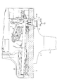
図2は、本発明の実施形態における自動演奏ピアノ1における脚桁4を含まない部分の断面構成を説明する図である。この断面構成は、鍵20の延びている方向に沿った断面について、鍵20が並ぶ方向に沿って見た場合における構成を示している。鍵20は、バランスピン7により回動自在に支持されている。鍵20の前端部(演奏者によって押下される側(図2左側))が押下されると、バランスピン7を中心に回動して、鍵20の後端部(バランスピン7に対して前端部と反対側の端部)が上昇する。そして、アクション機構6が動作してハンマが打弦することにより、音が発生するようになっている。
[Position of lock driving device 10]
FIG. 2 is a diagram illustrating a cross-sectional configuration of a portion not including the leg girder 4 in the automatic performance piano 1 according to the embodiment of the present invention. This cross-sectional configuration shows a configuration when the cross section along the extending direction of the key 20 is viewed along the direction in which the keys 20 are arranged. The key 20 is rotatably supported by the balance pin 7. When the front end of the key 20 (the side pressed by the performer (left side in FIG. 2)) is pressed, the key 20 rotates about the balance pin 7 and the rear end of the key 20 (the front end with respect to the balance pin 7). The end on the opposite side of the part rises. A sound is generated when the action mechanism 6 operates and the hammer strikes the string.

棚板3は、鍵20の後端部の下方に空間30aが構成されている。この空間30aは、棚板3の一部を上下方向に貫通するように削って構成され、鍵20の並ぶ方向に沿って延在する略直方体形状となっている。鍵駆動装置10は、鍵20に駆動力を与えて鍵20を駆動するアクチュエータの一例であるソレノイドが収納されているソレノイド収納部100a、および上述した制御信号に基づいてソレノイドを動作させる制御回路が構成された基板210(図8参照)を収納する基板収納部200aを有している。また、鍵駆動装置10は、棚板3にネジ15によりネジ止めされ、棚板3に固定されている。
鍵駆動装置10は、コントローラ11からの制御信号に基づいてソレノイドを動作させて、鍵20の後端部を突き上げることによって鍵20を回動させ、演奏者が鍵20の前端部を押下したときと同様な動作を実現する。
The shelf 3 has a space 30 a below the rear end of the key 20. The space 30a is formed by cutting a part of the shelf board 3 so as to penetrate in the vertical direction, and has a substantially rectangular parallelepiped shape extending along the direction in which the keys 20 are arranged. The key driving device 10 includes a solenoid housing portion 100a that houses a solenoid that is an example of an actuator that drives the key 20 by applying a driving force to the key 20, and a control circuit that operates the solenoid based on the control signal described above. It has the board | substrate storage part 200a which accommodates the comprised board | substrate 210 (refer FIG. 8). The key driving device 10 is fixed to the shelf board 3 by being screwed to the shelf board 3 with screws 15.
The key driving device 10 operates the solenoid based on a control signal from the controller 11 to rotate the key 20 by pushing up the rear end portion of the key 20, and when the performer depresses the front end portion of the key 20. The same operation is realized.

図3は、本発明の実施形態における自動演奏ピアノ1における脚桁4を含む部分の断面構成を説明する図である。図2に示す場合とは異なり、棚板3の下方には脚桁4が存在している。棚板3は、鍵20の後端部の下方に空間30bが構成されている。この空間30bは、棚板3を上下方向に貫通するように削って構成され、鍵20の並ぶ方向に沿って延在する略直方体形状となっている。空間30bは、空間30aと異なり、下方に脚桁4が存在し、鍵盤2と脚桁4との間に構成される空間を含んでいる。
上述した空間30aと空間30bとは、連続した空間を構成し、全体として略直方体形状となっている。以下、空間30aと空間30bとを総称して空間30という。
FIG. 3 is a diagram illustrating a cross-sectional configuration of a portion including the leg girder 4 in the automatic performance piano 1 according to the embodiment of the present invention. Unlike the case shown in FIG. 2, a leg girder 4 exists below the shelf 3. The shelf 3 has a space 30 b below the rear end of the key 20. The space 30b is formed by cutting through the shelf 3 so as to penetrate in the vertical direction, and has a substantially rectangular parallelepiped shape extending along the direction in which the keys 20 are arranged. Unlike the space 30a, the space 30b includes a leg girder 4 below and includes a space formed between the keyboard 2 and the leg girder 4.
The space 30a and the space 30b described above constitute a continuous space and have a substantially rectangular parallelepiped shape as a whole. Hereinafter, the space 30a and the space 30b are collectively referred to as the space 30.

この部分における鍵駆動装置10は、ソレノイドが収納されているソレノイド収納部100bを有しているが、制御回路が構成された基板を収納する基板収納部200aに相当する構成については有していない。ソレノイド収納部100bは、ソレノイド収納部100aと連続して構成され、下部に基板収納部200aに相当する構成を有しない部分をいう。図3においては、ソレノイド収納部100bは、他の構成と接触していないが、ソレノイド収納部100aと連続して構成されているため、他の構成との位置関係は固定されている。   The key driving device 10 in this portion has a solenoid housing portion 100b in which a solenoid is housed, but does not have a configuration corresponding to the substrate housing portion 200a that houses the substrate on which the control circuit is configured. . The solenoid housing portion 100b is configured to be continuous with the solenoid housing portion 100a, and refers to a portion that does not have a configuration corresponding to the substrate housing portion 200a at the bottom. In FIG. 3, the solenoid housing portion 100b is not in contact with other components, but is configured continuously with the solenoid housing portion 100a, and therefore the positional relationship with the other components is fixed.

図4は、本発明の実施形態における自動演奏ピアノ1の正面方向から見た場合の棚板3、脚桁4および鍵駆動装置10の位置関係を説明する図である。鍵駆動装置10は、低音側の鍵20を駆動する駆動ユニット10−L、高音側の鍵20を駆動する駆動ユニット10−U、および、駆動ユニット10−Lと駆動ユニット10−Uと連結する連結部300を有する。駆動ユニット10−L、10−Uは、それぞれ長尺状に構成され、上述したソレノイド収納部100a、100bの他、ソレノイド収納部100cを有している。上述したように、ソレノイド収納部100aの下部に基板収納部200aが存在し、ソレノイド収納部100b、100cの下部には存在しない。なお、基板収納部200aの側面には、空気が通過可能な複数の孔が設けられているが、設けられていなくてもよい。   FIG. 4 is a diagram for explaining the positional relationship among the shelf board 3, the leg girder 4, and the key driving device 10 when viewed from the front direction of the automatic performance piano 1 in the embodiment of the present invention. The key drive device 10 is connected to the drive unit 10-L that drives the low-frequency key 20, the drive unit 10-U that drives the high-frequency key 20, and the drive unit 10-L and the drive unit 10-U. A connecting portion 300 is provided. The drive units 10-L and 10-U are each formed in a long shape, and have a solenoid housing portion 100c in addition to the solenoid housing portions 100a and 100b described above. As described above, the substrate storage portion 200a exists under the solenoid storage portion 100a, and does not exist under the solenoid storage portions 100b and 100c. In addition, although the several hole which can pass air is provided in the side surface of the board | substrate storage part 200a, it does not need to be provided.

ソレノイド収納部100cは、ソレノイド収納部100bと同様に、ソレノイド収納部100aと連続して構成されている。また、ソレノイド収納部100cは、隣接する駆動ユニットと連結するための連結部300を取り付け可能に構成されている。この例においては、ソレノイド収納部100cは、下部に連結部300をネジ止めするためのネジ孔(図示略)を有している。   The solenoid housing portion 100c is configured continuously with the solenoid housing portion 100a, like the solenoid housing portion 100b. Moreover, the solenoid accommodating part 100c is comprised so that attachment of the connection part 300 for connecting with an adjacent drive unit is possible. In this example, the solenoid housing part 100c has a screw hole (not shown) for screwing the connecting part 300 in the lower part.

また、図4に示すように、ソレノイド収納部100cの下方には、ペダルレバー80が存在する。ペダルレバー80は、ペダル8が押下されると、ペダル8の動きに連動して動作し、アクション機構6に動作を伝達する。
以下、ソレノイド収納部100a、100b、100cを総称してソレノイド収納部100という。続いて、鍵駆動装置10の構成について説明する。
Further, as shown in FIG. 4, a pedal lever 80 exists below the solenoid housing portion 100c. The pedal lever 80 operates in conjunction with the movement of the pedal 8 when the pedal 8 is pressed, and transmits the operation to the action mechanism 6.
Hereinafter, the solenoid housing portions 100a, 100b, and 100c are collectively referred to as the solenoid housing portion 100. Next, the configuration of the lock driving device 10 will be described.

[鍵駆動装置10の構成]
図5は、本発明の実施形態における鍵駆動装置10の構成を説明する図である。図5(a)は、鍵駆動装置10を上方から見た図である。図5(b)は、鍵駆動装置10を自動演奏ピアノ1の正面(図4と同じ方向)から見た図である。鍵駆動装置10は、基板収納部200aの上面側(ソレノイド収納部100側)に、棚板3と接続して固定するときのネジ止めに用いられる開口部400を有する。また、ソレノイド収納部100の上面側には、鍵20に駆動力を与えるソレノイド101(図7、図8参照)におけるプランジャヘッド110の先端部分が突出している。この例においては、全ての鍵20に対応して88個のソレノイド101が存在するため、88個のプランジャヘッド110が突出している。ソレノイド収納部100は、これらのソレノイド101を鍵20の並ぶ方向に沿って2列に並んだ状態で収納するように、一方向に延びた形状になっている。
[Configuration of Key Drive Device 10]
FIG. 5 is a diagram illustrating the configuration of the lock driving device 10 according to the embodiment of the present invention. FIG. 5A is a view of the lock driving device 10 as viewed from above. FIG. 5B is a view of the key driving device 10 as viewed from the front of the automatic performance piano 1 (the same direction as FIG. 4). The key drive device 10 has an opening 400 used for screwing when connecting and fixing to the shelf board 3 on the upper surface side (solenoid storage unit 100 side) of the substrate storage unit 200a. Further, on the upper surface side of the solenoid housing portion 100, a tip portion of the plunger head 110 in the solenoid 101 (see FIGS. 7 and 8) that gives a driving force to the key 20 protrudes. In this example, since 88 solenoids 101 exist corresponding to all the keys 20, 88 plunger heads 110 protrude. The solenoid housing portion 100 has a shape extending in one direction so that these solenoids 101 are housed in two rows along the direction in which the keys 20 are arranged.

鍵駆動装置10は、上述したように、連結部300により連結された駆動ユニット10−L、10−Rを有している。駆動ユニット10−Lと駆動ユニット10−Uとは、連結部300を取り外すことにより、境界部Pにおいて分離可能に構成されている。   As described above, the lock driving device 10 includes the drive units 10-L and 10-R connected by the connecting unit 300. The drive unit 10-L and the drive unit 10-U are configured to be separable at the boundary portion P by removing the connecting portion 300.

図6は、本発明の実施形態における鍵駆動装置10が駆動ユニット毎に分離した場合の構成を説明する図である。図6(a)は、鍵駆動装置10を上方から見た図である。図6(b)は、鍵駆動装置10を自動演奏ピアノ1の正面(図4と同じ方向)から見た図である。図6に示すように、鍵駆動装置10は、連結部300を取り外すと、境界部Pにおいて駆動ユニット10−Lと駆動ユニット10−Uとに分離可能になっている。この境界部Pは、プランジャヘッド110(ソレノイド101)の配置に応じて、上方から見た場合に段差のある形状になっている。   FIG. 6 is a diagram illustrating a configuration when the lock driving device 10 according to the embodiment of the present invention is separated for each drive unit. FIG. 6A is a view of the lock driving device 10 as viewed from above. FIG. 6B is a view of the key drive device 10 as viewed from the front of the automatic performance piano 1 (the same direction as FIG. 4). As shown in FIG. 6, the key drive device 10 can be separated into the drive unit 10 -L and the drive unit 10 -U at the boundary portion P when the connecting portion 300 is removed. This boundary portion P has a stepped shape when viewed from above according to the arrangement of the plunger head 110 (solenoid 101).

図7は、図6に示す矢視VII−VII方向から見た鍵駆動装置10の断面図である。ソレノイド収納部100bには、上述したように、ソレノイド101が収納されている。ソレノイド101は、プランジャヘッド110が先端に取り付けられたプランジャ120とコイル130とを有している。プランジャ120は、コイル130に供給される電流に応じて上方に移動し、プランジャヘッド110を介して鍵20の後端部を突き上げる。なお、ソレノイド収納部100cについても、ソレノイド収納部100aと内部構成は同様である。   FIG. 7 is a cross-sectional view of the key drive device 10 as seen from the direction of arrows VII-VII shown in FIG. As described above, the solenoid 101 is accommodated in the solenoid accommodating portion 100b. The solenoid 101 has a plunger 120 and a coil 130 with a plunger head 110 attached to the tip. The plunger 120 moves upward according to the current supplied to the coil 130 and pushes up the rear end portion of the key 20 via the plunger head 110. The solenoid housing 100c has the same internal configuration as the solenoid housing 100a.

図8は、図6に示す矢視VIII−VIII方向から見た鍵駆動装置10の断面図である。ソレノイド収納部100aには、ソレノイド収納部100bと同様にソレノイド101が収納されている。基板収納部200aには、制御回路が構成された基板210が収納されている。制御回路は、コントローラ11から出力される制御信号に基づいて、ソレノイド101のコイル130に電流を供給してプランジャ120を動作させる回路である。この基板210には、ソレノイド収納部100aに収納されているソレノイド101のコイル130に電流を供給するだけでなく、ソレノイド収納部100b、100cに収納されているソレノイド101のコイル130に対しても電流を供給するように制御回路が構成されている。なお、各図の記載においては、基板210からソレノイド101のコイル130へ電流を供給する配線についての記載を省略している。また、この例においては、基板210は、1層で構成されているが、複数の層で構成されていてもよい。   FIG. 8 is a cross-sectional view of the key drive device 10 as seen from the direction of arrows VIII-VIII shown in FIG. The solenoid 101 is housed in the solenoid housing 100a in the same manner as the solenoid housing 100b. A substrate 210 having a control circuit is stored in the substrate storage portion 200a. The control circuit is a circuit that operates the plunger 120 by supplying a current to the coil 130 of the solenoid 101 based on a control signal output from the controller 11. The substrate 210 not only supplies current to the coil 130 of the solenoid 101 housed in the solenoid housing part 100a, but also supplies current to the coil 130 of the solenoid 101 housed in the solenoid housing parts 100b and 100c. The control circuit is configured to supply In the description of each figure, description of wiring for supplying current from the substrate 210 to the coil 130 of the solenoid 101 is omitted. In this example, the substrate 210 is composed of one layer, but may be composed of a plurality of layers.

[鍵駆動装置10の取り付け例]
自動演奏ピアノ1は、鍵駆動装置10をグランドピアノに取り付けて構成されたものである。一般的なグランドピアノへの鍵駆動装置10の取り付け例について、図9、図10、図11を用いて説明する。
[Attachment example of lock driving device 10]
The automatic performance piano 1 is configured by attaching a key driving device 10 to a grand piano. An example of attaching the key drive device 10 to a general grand piano will be described with reference to FIGS. 9, 10, and 11.

図9は、本発明の実施形態における鍵駆動装置10をグランドピアノに取り付ける例を説明する図である。図9は、グランドピアノの正面方向から見た場合の棚板3と脚桁4との位置関係を示している。一度も鍵駆動装置10を取り付けていないグランドピアノにおける棚板3は、空間30が存在しない状態である。そのため、作業者は、棚板3に対して上下方向に貫通するように削るなどの加工をして、図9に示すように、空間30を形成する。この空間30は、上述したように略直方体形状であり、鍵駆動装置10のソレノイド収納部100が挿入可能な大きさになっている。また、空間30の両端側は、鍵盤2の両端の鍵20よりも外側まで広がるように構成されている。なお、棚板3に構成される空間30のうち脚桁4の上方部分(空間30b)については、脚桁4を一旦取り外してから加工してもよい。また、この状態においては、ペダルレバー80は取り外されている。
このように棚板3に空間30が構成された状態において、作業者は、鍵駆動装置10を取り付ける。
FIG. 9 is a diagram illustrating an example in which the key driving device 10 according to the embodiment of the present invention is attached to a grand piano. FIG. 9 shows the positional relationship between the shelf board 3 and the leg girder 4 when viewed from the front direction of the grand piano. The shelf board 3 in the grand piano to which the key driving device 10 has never been attached is in a state where the space 30 does not exist. Therefore, the worker performs processing such as cutting so as to penetrate the shelf plate 3 in the vertical direction to form a space 30 as shown in FIG. As described above, the space 30 has a substantially rectangular parallelepiped shape, and is large enough to insert the solenoid housing portion 100 of the key driving device 10. In addition, both ends of the space 30 are configured to extend to the outside of the keys 20 at both ends of the keyboard 2. In addition, about the upper part (space 30b) of the leg girder 4 among the spaces 30 comprised in the shelf board 3, you may process after removing the leg girder 4 once. In this state, the pedal lever 80 is removed.
In this state where the space 30 is formed on the shelf board 3, the operator attaches the lock driving device 10.

図10は、本発明の実施形態における鍵駆動装置10をグランドピアノに取り付ける例を説明する図9に続く図である。図10に示すように、鍵駆動装置10は、駆動ユニット10−L、10−Uに分割された状態で、空間30に挿入される。このとき、駆動ユニット10−L、10−Uは、水平面から傾けられた状態で、ソレノイド収納部100bが空間30bに挿入される。駆動ユニット10−Lにおけるソレノイド収納部100の長手方向の全長と、駆動ユニット10−Uにおけるソレノイド収納部100の長手方向の全長との合計の長さは、空間30aの長手方向の長さ(両側にある脚桁4の間の長さ)よりも長い。したがって、作業者は、駆動ユニット10−L、10−Uを傾けた状態にして挿入する必要がある。なお、図10に示していないが、棚板3(空間30)の上方には、図3に示すように、鍵20が存在するため、駆動ユニット10−L、10−Uは、プランジャヘッド110が鍵20に接触しない程度に傾ける量を調整しながら挿入される。   FIG. 10 is a diagram following FIG. 9 for explaining an example in which the key driving device 10 according to the embodiment of the present invention is attached to the grand piano. As shown in FIG. 10, the lock driving device 10 is inserted into the space 30 in a state of being divided into drive units 10 -L and 10 -U. At this time, the solenoid housing portion 100b is inserted into the space 30b with the drive units 10-L and 10-U tilted from the horizontal plane. The total length of the solenoid housing portion 100 in the drive unit 10-L in the longitudinal direction and the overall length in the drive unit 10-U in the longitudinal direction of the solenoid housing portion 100 is the length in the longitudinal direction of the space 30a (both sides). Longer than the length between the leg girders 4). Therefore, the operator needs to insert the drive units 10-L and 10-U in an inclined state. Although not shown in FIG. 10, since the key 20 is present above the shelf 3 (space 30) as shown in FIG. 3, the drive units 10-L and 10-U are connected to the plunger head 110. Is inserted while adjusting the amount of tilting so as not to contact the key 20.

図11は、本発明の実施形態における鍵駆動装置10をグランドピアノに取り付ける例を説明する図10に続く図である。図11は、図10に示す状態から、駆動ユニット10−L、10−Uを水平な状態に移動させ、基板収納部200aの上面における開口部400が存在する部分が棚板3の下面3Dと接触した状態を示している。この状態においては、駆動ユニット10−Lと駆動ユニット10−Uとは、互いに分離した状態になっている。   FIG. 11 is a diagram following FIG. 10 for explaining an example in which the lock driving device 10 according to the embodiment of the present invention is attached to the grand piano. 11, the drive units 10-L and 10-U are moved from the state shown in FIG. 10 to a horizontal state, and the portion where the opening 400 is present on the upper surface of the substrate storage portion 200a is the lower surface 3D of the shelf board 3. The contact state is shown. In this state, the drive unit 10-L and the drive unit 10-U are separated from each other.

この状態において、作業者は、駆動ユニット10−Lと駆動ユニット10−Uとを近づけて接触させる前に、駆動ユニット10−Uにおける基板210と駆動ユニット10−Lにおける基板210とを電気的に接続させる。この例においては、駆動ユニット10−L、10−Uは、それぞれ、隣接する駆動ユニットにおける基板210と自身の基板210とを電気的に接続するためのケーブル(不図示)を有している。このケーブルについては、ソレノイド収納部100cの内部を通過して、境界部Pからソレノイド収納部100の外側に取り出せる構成となっている。それぞれのケーブルの先端に設けられたコネクタにより互いに接続されると、駆動ユニット10−Uにおける基板210と駆動ユニット10−Lにおける基板210とが電気的に接続されるようになっている。   In this state, the operator electrically connects the substrate 210 in the drive unit 10-U and the substrate 210 in the drive unit 10-L before bringing the drive unit 10-L and the drive unit 10-U into close contact with each other. Connect. In this example, each of the drive units 10-L and 10-U has a cable (not shown) for electrically connecting the board 210 and its own board 210 in the adjacent drive unit. This cable is configured to be able to pass through the inside of the solenoid housing portion 100c and be taken out from the boundary portion P to the outside of the solenoid housing portion 100. When connected to each other by a connector provided at the tip of each cable, the substrate 210 in the drive unit 10-U and the substrate 210 in the drive unit 10-L are electrically connected.

図12は、図11に示す鍵駆動装置10を下方から見た場合の鍵駆動装置10と棚板3との関係を示す図である。図12は、鍵駆動装置10を下方から見た場合であるから、棚板3の部分は、脚桁4が存在する部分を除いて、棚板3の下面3Dが見えている。作業者は、この状態から、駆動ユニット10−Lと駆動ユニット10−Uとを近づけて境界部Pを接触させ、連結部300が取り付ける。このとき、境界部Pは、段差のある形状になっているため、接続時の水平方向の位置合わせが容易になる。また、駆動ユニット10−L、10−Uの基板収納部200aの上面と棚板の下面3Dとが接触し、また、ソレノイド収納部100cの下部に取り付けられる連結部300により、さらに水平方向の位置合わせが容易になるとともに、上下方向の位置合わせも容易になる。また、連結部300は、隣接する駆動ユニットを接続するケーブルおよびコネクタのカバーとしても用いることができる。なお、駆動ユニット10−Uにおける基板210と駆動ユニット10−Lにおける基板210とを電気的に接続させるときに、上述のコネクタを用いる接続ではなく、取り付けられた連結部300を介して電気的に接続されるようにしてもよい。   FIG. 12 is a diagram illustrating a relationship between the key driving device 10 and the shelf board 3 when the key driving device 10 illustrated in FIG. 11 is viewed from below. Since FIG. 12 is a case where the key drive device 10 is seen from below, the lower surface 3D of the shelf 3 can be seen in the shelf 3 except for the portion where the leg girder 4 is present. From this state, the operator brings the drive unit 10-L and the drive unit 10-U closer to contact the boundary portion P, and the connecting portion 300 is attached. At this time, since the boundary portion P has a stepped shape, alignment in the horizontal direction at the time of connection becomes easy. Further, the upper surface of the substrate storage portion 200a of the drive units 10-L, 10-U and the lower surface 3D of the shelf board are in contact with each other, and the position in the horizontal direction is further increased by the connecting portion 300 attached to the lower portion of the solenoid storage portion 100c. The alignment becomes easy and the alignment in the vertical direction becomes easy. Moreover, the connection part 300 can be used also as a cover of the cable and connector which connect an adjacent drive unit. In addition, when the board | substrate 210 in the drive unit 10-U and the board | substrate 210 in the drive unit 10-L are electrically connected, it is not connected using the above-mentioned connector but electrically via the attached connection part 300. FIG. You may make it connect.

また、鍵駆動装置10をネジ15(図2参照)を開口部400に通し、棚板3にネジ止めすることにより、鍵駆動装置10が棚板3に固定される。固定されるときには、プランジャヘッド110の先端と鍵20との距離との調整がなされてもよい。   Further, the key driving device 10 is fixed to the shelf plate 3 by passing the screw 15 (see FIG. 2) through the opening 400 and screwing the key driving device 10 to the shelf plate 3. When fixed, the distance between the tip of the plunger head 110 and the key 20 may be adjusted.

また、このネジ止めは、駆動ユニット10−Lと駆動ユニット10−Uとが離れた状態において仮に行っておいてもよい。これは、駆動ユニット10−Lと駆動ユニット10−Uとを接触させるときに移動させる方向(鍵20が並ぶ方向)に開口部400の開口形状が延びているため、移動前にネジ止めをしても、駆動ユニット10−Lと駆動ユニット10−Uとを接触させる方向に移動させることができるためである。なお、ネジ止めせずに、駆動ユニット10−L、10−Uの空間30bに挿入された部分が脚桁4に支持された状態にして、駆動ユニット10−Lと駆動ユニット10−Uとを連結部300により連結して、その後に棚板3に固定するようにしてもよい。   Further, this screwing may be temporarily performed in a state where the drive unit 10-L and the drive unit 10-U are separated from each other. This is because the opening shape of the opening 400 extends in the direction of movement when the drive unit 10-L and the drive unit 10-U are brought into contact (the direction in which the keys 20 are arranged). However, this is because the drive unit 10-L and the drive unit 10-U can be moved in the direction of contact. It should be noted that the drive unit 10-L and the drive unit 10-U are connected to each other with the portions inserted into the space 30b of the drive units 10-L and 10-U supported by the leg girders 4 without being screwed. You may make it connect with the connection part 300, and you may make it fix to the shelf 3 after that.

その後、ソレノイド収納部100cの下部にペダルレバー80を取り付けた状態が、上述した図4に示す状態となる。その他、コントローラ11などをグランドピアノに取り付けることにより、本発明の自動演奏ピアノ1を構成することができる。
なお、自動演奏ピアノ1から鍵駆動装置10を取り外してメンテナンスなどを行う場合には、作業者は、この手順を逆に行い、メンテナンス済みの鍵駆動装置10を上述の手順で再び取り付ければよい。棚板3に空間30を構成した後であれば、脚桁4を棚板3から取り外さなくても、鍵駆動装置10の着脱が可能である。
Thereafter, the state in which the pedal lever 80 is attached to the lower part of the solenoid housing portion 100c is the state shown in FIG. 4 described above. In addition, the automatic performance piano 1 of this invention can be comprised by attaching the controller 11 etc. to a grand piano.
Note that when performing maintenance or the like by removing the key drive device 10 from the automatic performance piano 1, the operator reverses this procedure and reattaches the key drive device 10 that has been maintained in the above procedure. After the space 30 is formed on the shelf board 3, the key driving device 10 can be attached and detached without removing the leg beam 4 from the shelf board 3.

このように、鍵駆動装置10は、空間30bに位置する部分(ソレノイド収納部100b)においては、基板収納部200aに相当する構成を用いないようにして、棚板3より下方に突出しない構成であり、また、複数の駆動ユニットに分割された構成である。そのため、グランドピアノに鍵駆動装置10を取り付けるときには、複数の駆動ユニットに分割された状態で、ソレノイド収納部100bを空間30bに挿入した後に、駆動ユニットを接続すればよい。したがって、脚桁4の上方に鍵20が位置するグランドピアノに鍵駆動装置10を取り付ける場合であっても、脚桁4を切断除去せず、脚桁4の形状を維持したままにすることができる。さらに、ソレノイド収納部100cの下方にも基板収納部200aに相当する構成を用いないようにすることにより、ペダルレバー80の取り付け位置が大きく下方に変更されなくてもよい。すなわち、ペダルレバー80は、鍵駆動装置10を取り付ける前と後で取り付け位置が変更されないようにすることができ、変更させる必要があったとしても、わずかな移動に留めることができる。   As described above, the lock driving device 10 is configured not to protrude downward from the shelf 3 so as not to use the configuration corresponding to the substrate storage portion 200a in the portion (solenoid storage portion 100b) located in the space 30b. There is also a configuration divided into a plurality of drive units. Therefore, when attaching the key drive device 10 to the grand piano, the drive unit may be connected after the solenoid housing portion 100b is inserted into the space 30b in a state of being divided into a plurality of drive units. Therefore, even when the key driving device 10 is attached to the grand piano in which the key 20 is positioned above the leg girder 4, the leg girder 4 is not cut and removed, and the shape of the leg girder 4 is maintained. it can. Further, by not using a configuration corresponding to the substrate storage portion 200a below the solenoid storage portion 100c, the attachment position of the pedal lever 80 may not be greatly changed downward. In other words, the pedal lever 80 can be prevented from changing its attachment position before and after the key driving device 10 is attached, and can be kept in a slight movement even if it is necessary to change it.

<変形例>
以上、本発明の実施形態について説明したが、本発明は以下のように、さまざまな態様で実施可能である。
[変形例1]
上述した実施形態においては、ペダルレバー80の位置を大きく下方に移動させないようにするために、駆動ユニット10−L、10−Uにおけるソレノイド収納部100cの下部には、基板収納部200aに相当する構成を有していなかったが、ペダルレバー80の位置を下方に移動させてもよい場合には、ソレノイド収納部100cの下部に基板収納部200aに相当する構成が存在してもよい。
<Modification>
As mentioned above, although embodiment of this invention was described, this invention can be implemented in various aspects as follows.
[Modification 1]
In the above-described embodiment, in order to prevent the position of the pedal lever 80 from moving greatly downward, the lower part of the solenoid housing portion 100c in the drive units 10-L and 10-U corresponds to the substrate housing portion 200a. Although it did not have a configuration, when the position of the pedal lever 80 may be moved downward, a configuration corresponding to the substrate storage portion 200a may exist below the solenoid storage portion 100c.

図13は、本発明の変形例1における鍵駆動装置10Aの構成を説明する図である。図13(a)は、鍵駆動装置10Aを上方から見た図である。図13(b)は、鍵駆動装置10Aを自動演奏ピアノの正面(図4と同じ方向)から見た図である。この例における鍵駆動装置10Aは、実施形態におけるソレノイド収納部100cが存在せず、駆動ユニット10A−L、10A−Uともに、下部に基板収納部200Aaが存在するソレノイド収納部100Aaが境界部Pまで広がっている。この場合には、連結部300は、例えば、基板収納部200Aaの下部に取り付けるようにすればよい。なお、ソレノイド収納部100Abについては、実施形態におけるソレノイド収納部100bと同じ構成である。   FIG. 13 is a diagram illustrating the configuration of the lock driving device 10A according to the first modification of the present invention. FIG. 13A is a view of the lock driving device 10A as viewed from above. FIG. 13B is a diagram of the key drive device 10A as viewed from the front of the automatic performance piano (the same direction as FIG. 4). In the key drive device 10A in this example, the solenoid housing portion 100c in the embodiment does not exist, and the solenoid housing portion 100Aa in which the substrate housing portion 200Aa exists in the lower part of the drive units 10A-L and 10A-U is the boundary portion P. It has spread. In this case, the connecting part 300 may be attached to the lower part of the substrate storage part 200Aa, for example. The solenoid housing portion 100Ab has the same configuration as the solenoid housing portion 100b in the embodiment.

[変形例2]
上述した実施形態においては、基板収納部200aは、棚板3の下方に突出する構成になっていたが、ほとんど突出しないように構成されていてもよい。この場合の構成の例について、図14、図15を用いて説明する。
[Modification 2]
In the above-described embodiment, the substrate storage portion 200a is configured to protrude downward from the shelf board 3, but may be configured to hardly protrude. An example of the configuration in this case will be described with reference to FIGS.

図14は、本発明の変形例2における鍵駆動装置10Bの構成を説明する図である。図14(a)は、鍵駆動装置10Bを上方から見た図である。図14(b)は、鍵駆動装置10Bを自動演奏ピアノの正面(図4と同じ方向)から見た図である。図15は、図14に示す矢視XV−XV方向から見た鍵駆動装置10Bの断面図である。
図14、図15に示すように、駆動ユニット10B−L、10B−Uにおける基板収納部200Baは、実施形態における基板収納部200aのようにソレノイド収納部100aの下部に構成されるのではなく、側面から水平方向に、特に長尺状の駆動ユニット10B−L、10B−Uの短手方向(水平短手方向)に延びるように構成されている。なお、基板収納部200Baは、収納するものの大きさにより、上下方向および水平短手方向の双方に延びるように構成されてもよい。
棚板3と接する開口部400は、基板収納部200Baの下部に設けられている。したがって、鍵駆動装置10Bにおけるソレノイド収納部100Ba、100Bb、100Bcだけでなく、基板収納部200Baについても、棚板3の空間30に挿入されることになる。なお、棚板3の空間30は、実施形態と同様に直方体形状で容積を大きくした形状に構成されてもよいし、ソレノイド収納部100Ba、100Bb、100Bcおよび基板収納部200Baの外形に沿った形状に構成されてもよい。
FIG. 14 is a diagram illustrating the configuration of the lock driving device 10B according to the second modification of the present invention. FIG. 14A is a view of the lock driving device 10B as viewed from above. FIG. 14B is a diagram of the key driving device 10B as viewed from the front of the automatic performance piano (the same direction as FIG. 4). 15 is a cross-sectional view of the key drive device 10B as viewed from the direction of arrows XV-XV shown in FIG.
As shown in FIGS. 14 and 15, the substrate storage unit 200Ba in the drive units 10B-L and 10B-U is not configured below the solenoid storage unit 100a like the substrate storage unit 200a in the embodiment. It is configured to extend in the horizontal direction from the side surface, particularly in the short direction (horizontal short direction) of the long drive units 10B-L and 10B-U. The substrate storage unit 200Ba may be configured to extend in both the vertical direction and the horizontal short direction depending on the size of the storage.
The opening 400 in contact with the shelf board 3 is provided in the lower part of the substrate storage part 200Ba. Therefore, not only the solenoid housing portions 100Ba, 100Bb, and 100Bc in the key driving device 10B but also the substrate housing portion 200Ba is inserted into the space 30 of the shelf board 3. The space 30 of the shelf board 3 may be configured to have a rectangular parallelepiped shape with a large volume as in the embodiment, or a shape along the outer shape of the solenoid housing portions 100Ba, 100Bb, 100Bc and the substrate housing portion 200Ba. May be configured.

[変形例3]
上述した実施形態においては、自動演奏ピアノ1は、グランドピアノに鍵駆動装置10が取り付けられた構成であったが、グランドピアノ以外の鍵盤楽器、例えば、チェンバロなどのアコースティック楽器、電子ピアノなどに取り付けられていてもよい。すなわち、鍵盤2の一部が脚桁4の上方に位置する構成を有する鍵盤楽器であれば、どのような鍵盤楽器に対しても、鍵駆動装置10を取り付けることにより、自動演奏ピアノとして構成することができる。なお、鍵盤2の一部とは、必ずしも両端側に限らず、一端側であってもよいし、最高音または最低音の鍵20を必ずしも含むものではない。例えば、最低音から3から6番目までの鍵20の下方に脚桁4が位置するような場合も含む。
[Modification 3]
In the embodiment described above, the automatic performance piano 1 has a configuration in which the key driving device 10 is attached to the grand piano, but is attached to a keyboard instrument other than the grand piano, for example, an acoustic instrument such as a harpsichord, an electronic piano, or the like. It may be done. That is, any keyboard instrument having a configuration in which a part of the keyboard 2 is positioned above the leg girder 4 is configured as an automatic performance piano by attaching the key driving device 10 to any keyboard instrument. be able to. The part of the keyboard 2 is not necessarily limited to both ends, but may be one end, and does not necessarily include the highest tone or lowest tone key 20. For example, the case where the leg girder 4 is located below the third to sixth keys 20 from the lowest note is included.

[変形例4]
上述した実施形態においては、鍵駆動装置10がグランドピアノに取り付けられた状態では、脚桁4とソレノイド収納部100bとは接していなかったが、ソレノイド収納部100bの下部の一部と脚桁4の上面とが接する構成として、脚桁4が駆動ユニット10−L、10−Uを支持するようにしてもよい。この場合には、ソレノイド収納部100bの下部を脚桁4の上面に接する程度まで大きくした構成とすればよい。このようにすると、駆動ユニット10−L、10−Uを固定するときの棚板3にかかる負荷の一部を、脚桁4に分散させることもできる。この場合には、駆動ユニット10−L、10−Uは、棚板3にネジ止めされず、ビス止めなど、位置止めが可能な程度の固定方法であってもよい。
すなわち、上述した実施形態の構成においては、駆動ユニット10−L、10−Uが棚板3にネジ15によって止められ、棚板3は、重量および反力を受けるとともに前後左右の位置決めをした状態で駆動ユニット10−L、10−Uを支持していた。一方、本変形例においては、脚桁4が駆動ユニット10−L、10−Uの重量および反力を受けるため、駆動ユニット10−L、10−Uは、棚板3へのビス止めなどにより前後左右の位置決めがなされて、グランドピアノに取り付けられてもよい。
[Modification 4]
In the embodiment described above, when the key driving device 10 is attached to the grand piano, the leg girder 4 and the solenoid housing part 100b are not in contact with each other, but the lower part of the solenoid housing part 100b and the leg girder 4 are not in contact with each other. As a configuration in contact with the upper surface, the leg girder 4 may support the drive units 10-L and 10-U. In this case, the configuration may be such that the lower portion of the solenoid housing portion 100b is enlarged to the extent that the lower portion of the solenoid housing portion 100b contacts the upper surface of the leg girder 4. If it does in this way, a part of load concerning shelf board 3 at the time of fixing drive units 10-L and 10-U can also be distributed to leg girder 4. In this case, the driving units 10-L and 10-U may be fixed to the shelf plate 3 without screws, such as screws.
That is, in the configuration of the above-described embodiment, the drive units 10-L and 10-U are fixed to the shelf board 3 by the screws 15, and the shelf board 3 receives weight and reaction force and is positioned front and rear and left and right. The drive units 10-L and 10-U were supported. On the other hand, in this modified example, the leg girder 4 receives the weight and reaction force of the drive units 10-L, 10-U, so that the drive units 10-L, 10-U are secured by screws to the shelf plate 3 or the like. Positioning in the front-rear and left-right directions may be performed and attached to the grand piano.

[変形例5]
上述した実施形態においては、鍵駆動装置10は、2台の駆動ユニットに分割されていたが、3台以上に分割されていてもよい。その場合であっても、鍵駆動装置10の両端側に位置し、脚桁4の上方に位置する鍵20を駆動させるソレノイド101を有する駆動ユニットについては、実施形態における下部に基板収納部200aを有しないソレノイド収納部100bが存在する構成とすればよい。一方、両端側に位置しない駆動ユニットについては、その両端が隣接する他の駆動ユニットと連結可能に構成されていればよく、基板収納部200aに相当する構成が、駆動ユニット両端側に存在していてもよい。さらに、前記連結は、駆動ユニット外に設けた制御ユニットを介してそれぞれが連結されるようにしてもよい。
[Modification 5]
In the embodiment described above, the lock driving device 10 is divided into two drive units, but may be divided into three or more. Even in such a case, for the drive unit having the solenoid 101 that drives the key 20 located on both ends of the key drive device 10 and above the leg girder 4, the substrate storage portion 200a is provided in the lower part in the embodiment. What is necessary is just to set it as the structure which the solenoid accommodating part 100b which does not have exists. On the other hand, the drive unit that is not located at both ends only needs to be configured so that both ends can be connected to other adjacent drive units, and a configuration corresponding to the substrate storage portion 200a exists at both ends of the drive unit. May be. Furthermore, the connection may be made via a control unit provided outside the drive unit.

[変形例6]
上述した実施形態においては、連結部300により隣接する駆動ユニット10−Lと駆動ユニット10−Uとを連結していたが、棚板3への駆動ユニット10−Lおよび駆動ユニット10−Uの固定により、互いに再分離しないようになっていれば、必ずしも連結部300を有していなくてもよい。また、連結部300に相当する構成が駆動ユニット10−L、10−Uの少なくとも一方に設けられていてもよい。
一方、連結部300が存在する場合に、駆動ユニット10−L、10−Uを連結する以外の機能を有するようにしてもよい。例えば、連結部300の位置の近傍には、ペダルレバー80が位置することになるため、連結部300は、ペダルレバー80を支持する部品などが取り付け可能な構成となっていてもよいし、その部品が取り付けられた構成であってもよい。また、連結部300は、コントローラ11に相当する構成を有していてもよい。
[Modification 6]
In the above-described embodiment, the drive unit 10-L and the drive unit 10-U adjacent to each other are connected by the connecting part 300, but the drive unit 10-L and the drive unit 10-U are fixed to the shelf plate 3. Therefore, as long as they are not re-separated from each other, the connecting portion 300 is not necessarily required. Moreover, the structure corresponded to the connection part 300 may be provided in at least one of drive unit 10-L, 10-U.
On the other hand, when the connection part 300 exists, you may make it have functions other than connecting drive unit 10-L, 10-U. For example, since the pedal lever 80 is positioned in the vicinity of the position of the connecting portion 300, the connecting portion 300 may be configured to be able to attach a component or the like that supports the pedal lever 80. The structure to which components were attached may be sufficient. Further, the connecting part 300 may have a configuration corresponding to the controller 11.

[変形例7]
上述した実施形態において、基板収納部200aと同様に、ソレノイド収納部100には、冷却用の空気が通過可能な孔などが設けられていてもよい。
[Modification 7]
In the embodiment described above, similarly to the substrate storage unit 200a, the solenoid storage unit 100 may be provided with a hole through which cooling air can pass.

[変形例8]
上述した実施形態において、空間30の周囲における棚板3については、金属板などの補強部品を設けるようにして、強度を向上させるようにしてもよい。
[Modification 8]
In the above-described embodiment, the shelf plate 3 around the space 30 may be provided with reinforcing parts such as a metal plate to improve the strength.

[変形例9]
上述した実施形態においては、駆動ユニット10−L、10−Uの境界部Pの近傍にペダルレバー80が位置するように構成されていたが、境界部Pが必ずしもペダルレバー80の近傍に位置しなくてもよい。例えば、駆動ユニット10−Lが駆動ユニット10−Uよりも長く、駆動ユニット10−Lの下方にペダルレバー80が位置する場合には、ペダルレバー80近傍において基板収納部200aがソレノイド収納部100の下部に位置しないように構成してもよい。
[Modification 9]
In the embodiment described above, the pedal lever 80 is configured to be positioned in the vicinity of the boundary portion P of the drive units 10-L and 10-U. However, the boundary portion P is not necessarily positioned in the vicinity of the pedal lever 80. It does not have to be. For example, when the drive unit 10-L is longer than the drive unit 10-U and the pedal lever 80 is positioned below the drive unit 10-L, the substrate storage unit 200a is located near the pedal lever 80 in the vicinity of the solenoid storage unit 100. You may comprise so that it may not be located in the lower part.

1…自動演奏ピアノ、2…鍵盤、3…棚板、4…脚桁、5…脚部、6…アクション機構、7…バランスピン、8…ペダル、10,10A,10B…鍵駆動装置、10−L,10A−L,10B−L,10−U,10A−U,10B−U…駆動ユニット、11…コントローラ、15…ネジ、20…鍵、30,30a,30b…空間、80…ペダルレバー、100,100a,100Aa,100Ba,100b,100Ab,100Bb,100c,100Bc…ソレノイド収納部、101…ソレノイド、110…プランジャヘッド、120…プランジャ、130…コイル、200a,200Aa,200Ba…基板収納部、210…基板、300…連結部、400…開口部 DESCRIPTION OF SYMBOLS 1 ... Automatic performance piano, 2 ... Keyboard, 3 ... Shelf board, 4 ... Leg girder, 5 ... Leg part, 6 ... Action mechanism, 7 ... Balance pin, 8 ... Pedal 10, 10A, 10B ... Key drive device, 10 -L, 10A-L, 10B-L, 10-U, 10A-U, 10B-U ... drive unit, 11 ... controller, 15 ... screw, 20 ... key, 30, 30a, 30b ... space, 80 ... pedal lever 100, 100a, 100Aa, 100Ba, 100b, 100Ab, 100Bb, 100c, 100Bc ... Solenoid housing, 101 ... Solenoid, 110 ... Plunger head, 120 ... Plunger, 130 ... Coil, 200a, 200Aa, 200Ba ... Substrate housing, 210: substrate, 300: connecting portion, 400: opening

Claims (2)

脚桁の上方に棚板を介して鍵盤の一部が位置するように構成された鍵盤楽器に取り付けられ、入力される制御信号に応じて前記鍵盤を構成する複数の鍵を駆動する鍵駆動装置であって、
前記鍵を各々駆動する複数のアクチュエータ、および前記複数のアクチュエータの動作を前記制御信号に応じて制御する制御回路を有し、前記棚板の一部を除去して構成される上下方向に貫通した除去空間に挿入されて前記鍵盤楽器に取り付けられる長尺状の駆動ユニットを複数具備し、
前記駆動ユニットは、アクチュエータ収容部と制御回路収容部を有し、前記アクチュエータ収容部と前記制御回路収容部が前記駆動ユニットの水平短手方向に配置されることを特徴とする鍵駆動装置。
A key driving device that is attached to a keyboard musical instrument configured such that a part of the keyboard is positioned above the leg girder via a shelf board and drives a plurality of keys constituting the keyboard in response to an input control signal Because
A plurality of actuators for driving each of the keys, and a control circuit for controlling the operation of the plurality of actuators according to the control signal, are penetrated in the vertical direction configured by removing a part of the shelf board A plurality of long drive units inserted into the removal space and attached to the keyboard instrument are provided,
The drive unit includes an actuator housing portion and a control circuit housing portion, and the actuator housing portion and the control circuit housing portion are arranged in a horizontal lateral direction of the drive unit.
前記鍵駆動装置は、前記駆動ユニットが鍵盤楽器に取り付けられた場合に、前記棚板の下面と前記鍵駆動装置の下面とが略同一面を構成することを特徴とする請求項1に記載の鍵駆動装置。   2. The key drive device according to claim 1, wherein when the drive unit is attached to a keyboard instrument, the lower surface of the shelf plate and the lower surface of the key drive device form substantially the same surface. Key drive device.
JP2014193704A 2014-09-24 2014-09-24 Locking device Active JP5958514B2 (en)

Priority Applications (1)

Application Number Priority Date Filing Date Title
JP2014193704A JP5958514B2 (en) 2014-09-24 2014-09-24 Locking device

Applications Claiming Priority (1)

Application Number Priority Date Filing Date Title
JP2014193704A JP5958514B2 (en) 2014-09-24 2014-09-24 Locking device

Related Parent Applications (1)

Application Number Title Priority Date Filing Date
JP2011004082A Division JP5621602B2 (en) 2011-01-12 2011-01-12 Key drive device and keyboard instrument

Publications (2)

Publication Number Publication Date
JP2015018277A true JP2015018277A (en) 2015-01-29
JP5958514B2 JP5958514B2 (en) 2016-08-02

Family

ID=52439245

Family Applications (1)

Application Number Title Priority Date Filing Date
JP2014193704A Active JP5958514B2 (en) 2014-09-24 2014-09-24 Locking device

Country Status (1)

Country Link
JP (1) JP5958514B2 (en)

Citations (8)

* Cited by examiner, † Cited by third party
Publication number Priority date Publication date Assignee Title
JPH0547995U (en) * 1991-12-03 1993-06-25 株式会社河合楽器製作所 Self-playing piano
JPH09237082A (en) * 1995-12-28 1997-09-09 Yamaha Corp Automatic player for keyboard musical instrument
JPH11184460A (en) * 1997-12-22 1999-07-09 Kawai Musical Instr Mfg Co Ltd Keyboard driving device of automatic playing piano
JP2000338964A (en) * 1999-03-23 2000-12-08 Yamaha Corp Automatic performance device of keyboard instrument
JP2001034261A (en) * 1999-07-21 2001-02-09 Yamaha Corp Automatic playing device for keyboard instrument and plunger detector
JP2001306065A (en) * 2000-04-19 2001-11-02 Yamaha Corp Solenoid unit
JP2001343972A (en) * 2000-06-01 2001-12-14 Yamaha Corp Solenoid device and automatic playing device for keyboard instrument
JP2008281744A (en) * 2007-05-10 2008-11-20 Yamaha Corp Mounting structure of drive unit in automatic player piano

Patent Citations (8)

* Cited by examiner, † Cited by third party
Publication number Priority date Publication date Assignee Title
JPH0547995U (en) * 1991-12-03 1993-06-25 株式会社河合楽器製作所 Self-playing piano
JPH09237082A (en) * 1995-12-28 1997-09-09 Yamaha Corp Automatic player for keyboard musical instrument
JPH11184460A (en) * 1997-12-22 1999-07-09 Kawai Musical Instr Mfg Co Ltd Keyboard driving device of automatic playing piano
JP2000338964A (en) * 1999-03-23 2000-12-08 Yamaha Corp Automatic performance device of keyboard instrument
JP2001034261A (en) * 1999-07-21 2001-02-09 Yamaha Corp Automatic playing device for keyboard instrument and plunger detector
JP2001306065A (en) * 2000-04-19 2001-11-02 Yamaha Corp Solenoid unit
JP2001343972A (en) * 2000-06-01 2001-12-14 Yamaha Corp Solenoid device and automatic playing device for keyboard instrument
JP2008281744A (en) * 2007-05-10 2008-11-20 Yamaha Corp Mounting structure of drive unit in automatic player piano

Also Published As

Publication number Publication date
JP5958514B2 (en) 2016-08-02

Similar Documents

Publication Publication Date Title
JP5487608B2 (en) Electronic keyboard instrument
CN108630182B (en) Keyboard device and keyboard instrument
JP2010078790A (en) Keyboard device
US7816598B2 (en) Electronic keyboard musical instrument having key actuators
JP2010145600A (en) Electronic keyboard musical instrument
JP5621602B2 (en) Key drive device and keyboard instrument
JP2004070238A (en) Keyboard of keyboard instrument, keying device of keyboard instrument and its manufacturing method
US8013228B2 (en) Electronic keyboard musical instrument having key actuators
JP5958514B2 (en) Locking device
JP2015018278A (en) Key drive device and keyboard instrument
US20050066798A1 (en) Electronic keyboard instrument
JP5277836B2 (en) Keyboard device
CN101950555B (en) Keyboard device for electronic musical instrument
CN101950552B (en) Keyboard device for electronic musical instrument
WO2019038913A1 (en) Keyboard device
JPH0726893U (en) Automatic playing device
JP2009230001A (en) Keyboard device
JP2005284146A (en) Electronic keyboard instrument
JPH11184460A (en) Keyboard driving device of automatic playing piano
JP2002162969A (en) Keyboard device for electronic keyboard musical instrument
JP2009025687A (en) Piano
JP2004046147A (en) Performance apparatus
JP2007144588A (en) Robot control device
JP5526535B2 (en) Electronic keyboard instrument
JP5605454B2 (en) Electronic keyboard instrument

Legal Events

Date Code Title Description
A621 Written request for application examination

Free format text: JAPANESE INTERMEDIATE CODE: A621

Effective date: 20141022

A977 Report on retrieval

Free format text: JAPANESE INTERMEDIATE CODE: A971007

Effective date: 20150713

A131 Notification of reasons for refusal

Free format text: JAPANESE INTERMEDIATE CODE: A131

Effective date: 20150804

A521 Written amendment

Free format text: JAPANESE INTERMEDIATE CODE: A523

Effective date: 20151001

A131 Notification of reasons for refusal

Free format text: JAPANESE INTERMEDIATE CODE: A131

Effective date: 20160315

A521 Written amendment

Free format text: JAPANESE INTERMEDIATE CODE: A523

Effective date: 20160428

TRDD Decision of grant or rejection written
A01 Written decision to grant a patent or to grant a registration (utility model)

Free format text: JAPANESE INTERMEDIATE CODE: A01

Effective date: 20160524

A61 First payment of annual fees (during grant procedure)

Free format text: JAPANESE INTERMEDIATE CODE: A61

Effective date: 20160606

R151 Written notification of patent or utility model registration

Ref document number: 5958514

Country of ref document: JP

Free format text: JAPANESE INTERMEDIATE CODE: R151