JP2015017932A - Sox concentration detector of internal combustion engine - Google Patents
Sox concentration detector of internal combustion engine Download PDFInfo
- Publication number
- JP2015017932A JP2015017932A JP2013146279A JP2013146279A JP2015017932A JP 2015017932 A JP2015017932 A JP 2015017932A JP 2013146279 A JP2013146279 A JP 2013146279A JP 2013146279 A JP2013146279 A JP 2013146279A JP 2015017932 A JP2015017932 A JP 2015017932A
- Authority
- JP
- Japan
- Prior art keywords
- voltage
- sensor
- output current
- applied voltage
- sox
- Prior art date
- Legal status (The legal status is an assumption and is not a legal conclusion. Google has not performed a legal analysis and makes no representation as to the accuracy of the status listed.)
- Granted
Links
- 238000002485 combustion reaction Methods 0.000 title claims abstract description 73
- 230000003247 decreasing effect Effects 0.000 claims abstract description 75
- 238000001514 detection method Methods 0.000 claims description 218
- 230000007423 decrease Effects 0.000 claims description 65
- 239000000446 fuel Substances 0.000 claims description 47
- 238000011084 recovery Methods 0.000 claims description 21
- 231100000572 poisoning Toxicity 0.000 claims description 13
- 230000000607 poisoning effect Effects 0.000 claims description 13
- 230000005856 abnormality Effects 0.000 claims description 10
- 238000000034 method Methods 0.000 abstract description 22
- 229910052815 sulfur oxide Inorganic materials 0.000 description 370
- 239000007789 gas Substances 0.000 description 100
- PNEYBMLMFCGWSK-UHFFFAOYSA-N aluminium oxide Inorganic materials [O-2].[O-2].[O-2].[Al+3].[Al+3] PNEYBMLMFCGWSK-UHFFFAOYSA-N 0.000 description 78
- 229910052760 oxygen Inorganic materials 0.000 description 74
- 239000007784 solid electrolyte Substances 0.000 description 74
- 239000001301 oxygen Substances 0.000 description 72
- 230000000875 corresponding effect Effects 0.000 description 69
- QVGXLLKOCUKJST-UHFFFAOYSA-N atomic oxygen Chemical compound [O] QVGXLLKOCUKJST-UHFFFAOYSA-N 0.000 description 36
- -1 oxygen ion Chemical class 0.000 description 34
- 238000004364 calculation method Methods 0.000 description 30
- 238000009792 diffusion process Methods 0.000 description 19
- BASFCYQUMIYNBI-UHFFFAOYSA-N platinum Chemical group [Pt] BASFCYQUMIYNBI-UHFFFAOYSA-N 0.000 description 18
- 230000000694 effects Effects 0.000 description 17
- NINIDFKCEFEMDL-UHFFFAOYSA-N Sulfur Chemical compound [S] NINIDFKCEFEMDL-UHFFFAOYSA-N 0.000 description 14
- 239000002574 poison Substances 0.000 description 14
- 231100000614 poison Toxicity 0.000 description 14
- 239000011593 sulfur Substances 0.000 description 14
- 229910052717 sulfur Inorganic materials 0.000 description 14
- 230000002159 abnormal effect Effects 0.000 description 11
- 239000003054 catalyst Substances 0.000 description 10
- MCMNRKCIXSYSNV-UHFFFAOYSA-N Zirconium dioxide Chemical compound O=[Zr]=O MCMNRKCIXSYSNV-UHFFFAOYSA-N 0.000 description 8
- 238000006243 chemical reaction Methods 0.000 description 8
- 230000006870 function Effects 0.000 description 8
- NNDLQUNWZOIESH-UHFFFAOYSA-N 8-hydroxy-7-[[7-[(8-hydroxy-5-sulfoquinoline-7-carbonyl)amino]-4-[3-[(8-hydroxy-5-sulfoquinoline-7-carbonyl)amino]propyl]heptyl]carbamoyl]quinoline-5-sulfonic acid Chemical compound C1=CC=NC2=C(O)C(C(=O)NCCCC(CCCNC(=O)C=3C(=C4N=CC=CC4=C(C=3)S(O)(=O)=O)O)CCCNC(=O)C3=C(C4=NC=CC=C4C(=C3)S(O)(=O)=O)O)=CC(S(O)(=O)=O)=C21 NNDLQUNWZOIESH-UHFFFAOYSA-N 0.000 description 6
- 239000000956 alloy Substances 0.000 description 6
- 229910045601 alloy Inorganic materials 0.000 description 6
- 230000001276 controlling effect Effects 0.000 description 6
- 238000002347 injection Methods 0.000 description 6
- 239000007924 injection Substances 0.000 description 6
- 239000000203 mixture Substances 0.000 description 6
- 229910052697 platinum Inorganic materials 0.000 description 6
- 229910052703 rhodium Inorganic materials 0.000 description 6
- 239000010948 rhodium Substances 0.000 description 6
- MHOVAHRLVXNVSD-UHFFFAOYSA-N rhodium atom Chemical compound [Rh] MHOVAHRLVXNVSD-UHFFFAOYSA-N 0.000 description 6
- 238000005086 pumping Methods 0.000 description 4
- 238000011144 upstream manufacturing Methods 0.000 description 4
- 229910002091 carbon monoxide Inorganic materials 0.000 description 2
- 230000003915 cell function Effects 0.000 description 2
- 230000006835 compression Effects 0.000 description 2
- 238000007906 compression Methods 0.000 description 2
- 230000002596 correlated effect Effects 0.000 description 2
- TXKMVPPZCYKFAC-UHFFFAOYSA-N disulfur monoxide Inorganic materials O=S=S TXKMVPPZCYKFAC-UHFFFAOYSA-N 0.000 description 2
- 238000002474 experimental method Methods 0.000 description 2
- 150000002926 oxygen Chemical class 0.000 description 2
- XTQHKBHJIVJGKJ-UHFFFAOYSA-N sulfur monoxide Chemical compound S=O XTQHKBHJIVJGKJ-UHFFFAOYSA-N 0.000 description 2
- 230000000630 rising effect Effects 0.000 description 1
Images


Landscapes
- Exhaust Gas After Treatment (AREA)
Abstract
Description
本発明は、内燃機関の特定成分パラメータ検出装置に関する。 The present invention relates to a specific component parameter detection apparatus for an internal combustion engine.
ガス混合物中の含酸素ガスの相対的量の測定用センサが特許文献1に記載されている。このセンサは2つのポンプセルを有する。これらポンプセルは直列的に配置されている。このセンサでは、上流側のポンプセルに低電圧を印加することによって、ガス混合物中の一部の含酸素ガス(特に、O2)を排除し、下流側のポンプセンサに高電圧を印加することによって、ガス混合物中の残りの含酸素ガス(特に、H2OとCO2)の相対的量が測定される。 A sensor for measuring the relative amount of oxygen-containing gas in a gas mixture is described in US Pat. This sensor has two pump cells. These pump cells are arranged in series. In this sensor, by applying a low voltage to the upstream pump cell, part of the oxygen-containing gas (especially O 2 ) in the gas mixture is eliminated, and by applying a high voltage to the downstream pump sensor. , The relative amounts of the remaining oxygenated gases (especially H 2 O and CO 2 ) in the gas mixture are measured.
ところで、限界電流式センサが知られている。このセンサでは、被検ガス中の特定成分に関するパラメータ(以下「特定成分パラメータ」)の検出に際し、一般的には、或る一定の電圧が印加される。しかしながら、こうした電圧の印加手法では、容易には精度良く検出できない特定成分パラメータ(たとえば、内燃機関の排気中のSOx濃度)が存在する。 By the way, a limit current type sensor is known. In this sensor, when a parameter related to a specific component in the gas to be detected (hereinafter referred to as “specific component parameter”) is detected, a certain voltage is generally applied. However, in such a voltage application method, there are specific component parameters (for example, SOx concentration in the exhaust gas of an internal combustion engine) that cannot be easily detected with high accuracy.
ところが、本願の発明者らの研究により、限界電流式センサへの電圧の印加手法に工夫を凝らせば、従来では精度良く検出できなかった特定成分パラメータを限界電流式センサによって精度良く検出できることが判明した。 However, it has been found by the inventors' research that if a method for applying a voltage to a limit current sensor is devised, a specific component parameter that could not be detected with high accuracy can be detected with a limit current sensor with high accuracy. did.
こうした本願の発明者らの知見に基づき、本発明の目的は、被検ガス中の特定成分に関するパラメータを限界電流式センサによって精度良く検出することにある。 Based on such knowledge of the inventors of the present application, an object of the present invention is to accurately detect a parameter related to a specific component in a test gas by a limiting current sensor.
本願の1つの発明は、限界電流式センサを有する内燃機関の特定成分パラメータ検出装置に関する。そして、本発明の特定成分パラメータ検出装置は、前記センサへの印加電圧(以下単に「印加電圧」)を所定電圧から低下させたときの前記センサの出力電流(以下単に「出力電流」)を用いて被検ガス中の特定成分に関するパラメータ(以下「特定成分パラメータ」)を検出する検出部を有する。 One invention of this application is related with the specific component parameter detection device of an internal-combustion engine which has a limiting current type sensor. The specific component parameter detection apparatus of the present invention uses the output current of the sensor (hereinafter simply referred to as “output current”) when the voltage applied to the sensor (hereinafter simply referred to as “applied voltage”) is reduced from a predetermined voltage. And a detection unit for detecting a parameter related to a specific component in the test gas (hereinafter referred to as “specific component parameter”).
これによれば、特定成分パラメータを検出することができる。特に、印加電圧が一定の電圧に維持されているときの出力電流に占める特定成分の影響、または、印加電圧が上昇されたときの出力電流に占める特定成分の影響が、同出力電流に占める他の成分の影響に比べて小さい場合であっても、印加電圧が所定電圧から低下されたときの出力電流に占める特定成分の影響が、同出力電流に占める他の成分の影響に比べて大きい場合、特定成分パラメータを精度良く検出することができる。 According to this, the specific component parameter can be detected. In particular, the influence of a specific component on the output current when the applied voltage is maintained at a constant voltage, or the influence of the specific component on the output current when the applied voltage is increased Even when the effect of the component is small, the effect of a specific component on the output current when the applied voltage is reduced from the specified voltage is greater than the effect of other components on the output current. The specific component parameter can be detected with high accuracy.
また、前記特定成分は、たとえば、SOxである。この場合、SOxに関するパラメータを検出することができる。 The specific component is, for example, SOx. In this case, a parameter relating to SOx can be detected.
また、前記検出部は、前記パラメータ検出用の出力電流として、印加電圧を前記所定電圧から低下させたときの出力電流のピーク値を、前記パラメータ検出用の出力電流として用いると好ましい。ピーク値は、印加電圧の低下中の出力電流のうち、最も小さい出力電流(または、最も大きい出力電流)である。したがって、ピーク値は、特定成分パラメータに精度良く対応する出力電流であると言える。このため、パラメータ検出用の出力電流としてピーク値を用いることによって、特定成分パラメータをより精度良く検出することができる。 The detection unit preferably uses, as the parameter detection output current, a peak value of the output current obtained when the applied voltage is reduced from the predetermined voltage as the parameter detection output current. The peak value is the smallest output current (or the largest output current) among the output currents when the applied voltage is decreasing. Therefore, it can be said that the peak value is an output current corresponding to the specific component parameter with high accuracy. For this reason, the specific component parameter can be detected with higher accuracy by using the peak value as the output current for parameter detection.
また、前記検出部は、前記所定電圧の印加前に当該所定電圧よりも低い電圧を印加しておき、印加電圧を前記所定電圧まで上昇させ、その後、印加電圧を低下させたときの出力電流を、前記パラメータ検出用の出力電流として用いるようにしてもよい。この場合、印加電圧の低下開始前にセンサに印加させておく電圧は、前記所定電圧よりも低い。このため、印加電圧の低下開始前にセンサに印加させておく電圧が前記所定電圧である場合に比べて、特定成分パラメータ検出に消費される電力を少なくすることができる。 The detection unit applies a voltage lower than the predetermined voltage before applying the predetermined voltage, increases the applied voltage to the predetermined voltage, and then outputs an output current when the applied voltage is decreased. The output current for parameter detection may be used. In this case, the voltage applied to the sensor before the start of the decrease in the applied voltage is lower than the predetermined voltage. For this reason, compared with the case where the voltage applied to the sensor before the start of the fall of an applied voltage is the said predetermined voltage, the electric power consumed for a specific component parameter detection can be decreased.
また、前記所定電圧が0.8V以上の電圧であると好ましい。これによれば、SOxに関するパラメータに精度良く対応する出力電流を得ることができ、ひいては、SOxに関するパラメータを精度良く検出することができる。 The predetermined voltage is preferably 0.8 V or more. According to this, it is possible to obtain an output current corresponding to the parameter related to SOx with high accuracy, and to detect the parameter related to SOx with high accuracy.
また、前記所定電圧からの印加電圧の低下終了時点の印加電圧が0.7V以下の電圧であると好ましい。これによれば、SOxに関するパラメータに精度良く対応する出力電流を得ることができ、ひいては、SOxに関するパラメータを精度良く検出することができる。 Moreover, it is preferable that the applied voltage at the end of the decrease in the applied voltage from the predetermined voltage is a voltage of 0.7 V or less. According to this, it is possible to obtain an output current corresponding to the parameter related to SOx with high accuracy, and to detect the parameter related to SOx with high accuracy.
また、前記検出部は、印加電圧を前記所定電圧から低下させるときの電圧変化の周波数を100Hz以下の周波数に設定するようにしてもよい。これによれば、特定成分パラメータに精度良く対応する出力電流を確実に得ることができ、ひいては、特定成分パラメータを精度良く検出することができる。 The detection unit may set the frequency of voltage change when the applied voltage is lowered from the predetermined voltage to a frequency of 100 Hz or less. According to this, it is possible to reliably obtain an output current corresponding to the specific component parameter with high accuracy, and to detect the specific component parameter with high accuracy.
また、前記検出部は、前記所定電圧よりも低い電圧を印加してから前記所定電圧まで印加電圧を上昇させた後に印加電圧を前記所定電圧から低下させるときの電圧変化の周波数を100Hz以下の周波数に設定するようにしてもよい。これによれば、特定成分パラメータに精度良く対応する出力電流を確実に得ることができ、ひいては、特定成分パラメータを精度良く検出することができる。 Further, the detection unit applies a voltage change frequency of 100 Hz or less when the applied voltage is decreased from the predetermined voltage after increasing the applied voltage to the predetermined voltage after applying a voltage lower than the predetermined voltage. You may make it set to. According to this, it is possible to reliably obtain an output current corresponding to the specific component parameter with high accuracy, and to detect the specific component parameter with high accuracy.
また、前記内燃機関が、たとえば、ガソリンエンジンである。ガソリンエンジンは、大部分の機関運転領域において空燃比が理論空燃比で運転される。したがって、被検ガスである排気中の酸素濃度が低い。このため、特定成分パラメータを検出しやすい。 The internal combustion engine is, for example, a gasoline engine. The gasoline engine is operated at a stoichiometric air-fuel ratio in most engine operating ranges. Therefore, the oxygen concentration in the exhaust gas that is the test gas is low. For this reason, it is easy to detect a specific component parameter.
また、前記特定成分パラメータ検出装置は、前記センサへの印加電圧を前記所定電圧から低下させたときの前記センサの出力電流の絶対値が第1の所定値以上である場合、S被毒回復制御を実行する制御部をさらに有していてもよい。これによれば、S被毒によるセンサの検出精度の低下が生じている可能性がない場合に限り、特定成分パラメータが検出される。このため、特定成分パラメータをより精度良く検出することができる。 In addition, the specific component parameter detection device performs S poison recovery control when the absolute value of the output current of the sensor when the applied voltage to the sensor is reduced from the predetermined voltage is equal to or greater than a first predetermined value. You may have further the control part which performs. According to this, the specific component parameter is detected only when there is no possibility that the detection accuracy of the sensor is reduced due to S poisoning. For this reason, the specific component parameter can be detected with higher accuracy.
また、前記特定成分パラメータ検出装置は、前記センサへの印加電圧を前記所定電圧から低下させたときの前記センサへの出力電流の絶対値が第2の所定値以上である場合、燃料性状の異常を警告する制御部をさらに有していてもよい。これによれば、燃料性状が異常である可能性がある場合、当該特定成分パラメータ検出装置の利用者は、燃料性状が異常である可能性があることを知ることができる。 In addition, the specific component parameter detection device detects an abnormality in the fuel property when the absolute value of the output current to the sensor when the voltage applied to the sensor is reduced from the predetermined voltage is equal to or greater than a second predetermined value. You may further have a control part which warns. According to this, when there is a possibility that the fuel property is abnormal, the user of the specific component parameter detection device can know that the fuel property may be abnormal.
本願の別の発明は、限界電流式センサを有する内燃機関における特定成分パラメータ検出方法に関する。そして、この方法は、前記センサへの印加電圧を所定電圧から低下させる電圧低下ステップと、該電圧低下ステップ中の前記センサの出力電流を取得する出力電流取得ステップと、該出力電流取得ステップにおいて取得された出力電流を用いて被検ガス中の特定成分に関するパラメータを検出する特定成分パラメータ検出ステップと、を具備する。 Another invention of the present application relates to a specific component parameter detection method in an internal combustion engine having a limiting current type sensor. In this method, the voltage applied to the sensor is reduced from a predetermined voltage, a voltage reduction step, an output current acquisition step for acquiring the output current of the sensor during the voltage reduction step, and an output current acquisition step. And a specific component parameter detecting step of detecting a parameter related to the specific component in the test gas using the output current.
これによれば、特定成分パラメータを検出することができる。特に、印加電圧が一定の電圧に維持されているときの出力電流に占める特定成分の影響、または、印加電圧が上昇されたときの出力電流に占める特定成分の影響が、同出力電流に占める他の成分の影響に比べて小さい場合であっても、印加電圧が所定電圧から低下されたときの出力電流に占める特定成分の影響が、同出力電流に占める他の成分の影響に比べて大きい場合、特定成分パラメータを精度良く検出することができる。 According to this, the specific component parameter can be detected. In particular, the influence of a specific component on the output current when the applied voltage is maintained at a constant voltage, or the influence of the specific component on the output current when the applied voltage is increased Even when the effect of the component is small, the effect of a specific component on the output current when the applied voltage is reduced from the specified voltage is greater than the effect of other components on the output current. The specific component parameter can be detected with high accuracy.
なお、前記出力電流取得ステップにおいて、前記センサの出力電流のピーク値を取得すると好ましい。ピーク値は、印加電圧の低下中の出力電流のうち、最も小さい出力電流(または、最も大きい出力電流)である。したがって、ピーク値は、特定成分パラメータに精度良く対応する出力電流であると言える。このため、パラメータ検出用の出力電流としてピーク値を用いることによって、特定成分パラメータをより精度良く検出することができる。 In the output current acquisition step, it is preferable to acquire a peak value of the output current of the sensor. The peak value is the smallest output current (or the largest output current) among the output currents when the applied voltage is decreasing. Therefore, it can be said that the peak value is an output current corresponding to the specific component parameter with high accuracy. For this reason, the specific component parameter can be detected with higher accuracy by using the peak value as the output current for parameter detection.
また、上記方法が、前記所定電圧の印加前に当該所定電圧よりも低い電圧を印加しておき、印加電圧を前記所定電圧まで上昇させる電圧上昇ステップであって、前記電圧低下ステップの前に実行される電圧上昇ステップをさらに具備していてもよい。この場合、印加電圧の低下開始前にセンサに印加させておく電圧は、前記所定電圧よりも低い。このため、印加電圧の低下開始前にセンサに印加させておく電圧が前記所定電圧である場合に比べて、特定成分パラメータ検出に消費される電力を少なくすることができる。 Further, the above method is a voltage increasing step in which a voltage lower than the predetermined voltage is applied before the predetermined voltage is applied, and the applied voltage is increased to the predetermined voltage, and is executed before the voltage decreasing step. The step of increasing the voltage may be further included. In this case, the voltage applied to the sensor before the start of the decrease in the applied voltage is lower than the predetermined voltage. For this reason, compared with the case where the voltage applied to the sensor before the start of the fall of an applied voltage is the said predetermined voltage, the electric power consumed for a specific component parameter detection can be decreased.
また、上記方法によって検出される特定成分に関するパラメータは、たとえば、SOxに関するパラメータである。この場合、SOxに関するパラメータを検出することができる。 The parameter related to the specific component detected by the above method is, for example, a parameter related to SOx. In this case, a parameter relating to SOx can be detected.
また、上記方法において、前記所定電圧が0.8V以上の電圧であると好ましい。これによれば、SOxに関するパラメータに精度良く対応する出力電流を得ることができ、ひいては、SOxに関するパラメータを精度良く検出することができる。 Moreover, in the said method, it is preferable in the said predetermined voltage being a voltage more than 0.8V. According to this, it is possible to obtain an output current corresponding to the parameter related to SOx with high accuracy, and to detect the parameter related to SOx with high accuracy.
また、前記電圧低下ステップにおいて前記所定電圧からの印加電圧の低下終了時点の印加電圧が0.7V以下の電圧であると好ましい。これによれば、SOxに関するパラメータに精度良く対応する出力電流を得ることができ、ひいては、SOxに関するパラメータを精度良く検出することができる。 In the voltage drop step, it is preferable that the applied voltage at the end of the drop of the applied voltage from the predetermined voltage is a voltage of 0.7 V or less. According to this, it is possible to obtain an output current corresponding to the parameter related to SOx with high accuracy, and to detect the parameter related to SOx with high accuracy.
また、前記電圧低下ステップにおいて印加電圧を前記所定電圧から低下させるときの電圧変化の周波数が100Hz以下の周波数であると好ましい。これによれば、特定成分パラメータに精度良く対応する出力電流を確実に得ることができ、ひいては、特定成分パラメータを精度良く検出することができる。 Moreover, it is preferable that the frequency of the voltage change when the applied voltage is reduced from the predetermined voltage in the voltage reduction step is a frequency of 100 Hz or less. According to this, it is possible to reliably obtain an output current corresponding to the specific component parameter with high accuracy, and to detect the specific component parameter with high accuracy.
また、前記電圧上昇ステップにおいて印加電圧を前記所定電圧まで上昇させるときの電圧変化の周波数が100Hz以下の周波数であると好ましい。これによれば、特定成分パラメータに精度良く対応する出力電流を確実に得ることができ、ひいては、特定成分パラメータを精度良く検出することができる。 Moreover, it is preferable that the frequency of the voltage change when raising the applied voltage to the predetermined voltage in the voltage raising step is a frequency of 100 Hz or less. According to this, it is possible to reliably obtain an output current corresponding to the specific component parameter with high accuracy, and to detect the specific component parameter with high accuracy.
また、上記方法が実行される内燃機関が、たとえば、ガソリンエンジンである。ガソリンエンジンは、大部分の機関運転領域において空燃比が理論空燃比で運転される。したがって、被検ガスである排気中の酸素濃度が低い。このため、特定成分パラメータを検出しやすい。 The internal combustion engine in which the above method is executed is, for example, a gasoline engine. The gasoline engine is operated at a stoichiometric air-fuel ratio in most engine operating ranges. Therefore, the oxygen concentration in the exhaust gas that is the test gas is low. For this reason, it is easy to detect a specific component parameter.
本願のさらに別の発明は、限界電流式センサに関する。本発明の限界電流式センサは、印加電圧を所定電圧から低下させたときの当該センサの出力電流(以下単に「出力電流」)を用いて被検ガス中の特定成分に関するパラメータ(以下「特定成分パラメータ」)を検出するために用いられる。 Still another invention of the present application relates to a limiting current type sensor. The limiting current type sensor of the present invention uses a parameter relating to a specific component in a test gas (hereinafter referred to as “specific component”) using an output current of the sensor when the applied voltage is reduced from a predetermined voltage (hereinafter simply referred to as “output current”). Parameter ") is used to detect.
これによれば、特定成分パラメータを検出するための限界電流式センサを提供することができる。特に、印加電圧が一定の電圧に維持されているときの出力電流に占める特定成分の影響、または、印加電圧が上昇されたときの出力電流に占める特定成分の影響が、同出力電流に占める他の成分の影響に比べて小さい場合であっても、印加電圧が所定電圧から低下されたときの出力電流に占める特定成分の影響が、同出力電流に占める他の成分の影響に比べて大きい場合、特定成分パラメータを精度良く検出するための限界電流式センサを提供することができる。 According to this, it is possible to provide a limiting current type sensor for detecting a specific component parameter. In particular, the influence of a specific component on the output current when the applied voltage is maintained at a constant voltage, or the influence of the specific component on the output current when the applied voltage is increased Even when the effect of the component is small, the effect of a specific component on the output current when the applied voltage is reduced from the specified voltage is greater than the effect of other components on the output current. It is possible to provide a limiting current type sensor for accurately detecting a specific component parameter.
また、印加電圧を前記所定電圧から低下させたときの出力電流のピーク値を、前記パラメータ検出用の出力電流として用いて前記パラメータを検出するために本発明の限界電流式センサが用いられると好ましい。ピーク値は、印加電圧の低下中の出力電流のうち、最も小さい出力電流(または、最も大きい出力電流)である。したがって、ピーク値は、特定成分パラメータに精度良く対応する出力電流であると言える。このため、パラメータ検出用の出力電流としてピーク値を用いることによって、特定成分パラメータを精度良く検出するための限界電流式センサを提供することができる。 Further, it is preferable that the limit current sensor of the present invention is used to detect the parameter by using the peak value of the output current when the applied voltage is lowered from the predetermined voltage as the output current for parameter detection. . The peak value is the smallest output current (or the largest output current) among the output currents when the applied voltage is decreasing. Therefore, it can be said that the peak value is an output current corresponding to the specific component parameter with high accuracy. Therefore, by using the peak value as the parameter detection output current, it is possible to provide a limiting current sensor for accurately detecting the specific component parameter.
また、前記所定電圧の印加前に当該所定電圧よりも低い電圧を印加しておき、印加電圧を前記所定電圧まで上昇させ、その後、印加電圧を低下させたときの出力電流を、前記パラメータ検出用の出力電流として用いて前記パラメータを検出するために本発明の限界電流式センサが用いられてもよい。この場合、印加電圧の低下開始前にセンサに印加させておく電圧は、所定電圧よりも低い。このため、印加電圧の低下開始前にセンサに印加させておく電圧が所定電圧である場合に比べて、少ない消費電力によって特定成分パラメータを検出するための限界電流式センサを提供することができる。 In addition, a voltage lower than the predetermined voltage is applied before the predetermined voltage is applied, the applied voltage is increased to the predetermined voltage, and then the output current when the applied voltage is decreased is used for the parameter detection. The limiting current type sensor of the present invention may be used to detect the parameter by using it as the output current. In this case, the voltage applied to the sensor before the applied voltage starts to decrease is lower than the predetermined voltage. Therefore, it is possible to provide a limiting current type sensor for detecting a specific component parameter with less power consumption compared to a case where the voltage applied to the sensor before the start of the decrease in applied voltage is a predetermined voltage.
また、本発明の限界電流式センサは、たとえば、前記パラメータとしてSOxに関するパラメータを検出するために用いられる。この場合、SOxに関するパラメータを検出するための限界電流式センサを提供することができる。 Moreover, the limiting current type sensor of the present invention is used, for example, for detecting a parameter relating to SOx as the parameter. In this case, it is possible to provide a limiting current type sensor for detecting a parameter related to SOx.
また、前記所定電圧が0.8V以上の電圧に設定されて本発明の限界電流式センサが用いられると好ましい。これによれば、SOxに関するパラメータに精度良く対応する出力電流を得ることができ、ひいては、SOxに関するパラメータを精度良く検出するための限界電流式センサを提供することができる。 In addition, it is preferable that the limit current sensor of the present invention is used with the predetermined voltage set to a voltage of 0.8 V or more. According to this, it is possible to obtain an output current corresponding to the SOx-related parameter with high accuracy, and thus it is possible to provide a limit current type sensor for accurately detecting the SOx-related parameter.
また、前記所定電圧から低下させたときの電圧が0.7V以下の電圧に設定されて本発明の限界電流式センサが用いられると好ましい。これによれば、SOxに関するパラメータに精度良く対応する出力電流を得ることができ、ひいては、SOxに関するパラメータを精度良く検出するための限界電流式センサを提供することができる。 Further, it is preferable that the voltage when the voltage is lowered from the predetermined voltage is set to a voltage of 0.7 V or less and the limiting current type sensor of the present invention is used. According to this, it is possible to obtain an output current corresponding to the SOx-related parameter with high accuracy, and thus it is possible to provide a limit current type sensor for accurately detecting the SOx-related parameter.
また、印加電圧を前記所定電圧から低下させるときの電圧変化の周波数が100Hz以下の周波数に設定されて本発明の限界電流式センサが用いられると好ましい。これによれば、特定成分パラメータに精度良く対応する出力電流を確実に得ることができ、ひいては、特定成分パラメータを精度良く検出するための限界電流式センサを提供することができる。 Further, it is preferable that the limit current sensor of the present invention is used by setting the frequency of voltage change when the applied voltage is lowered from the predetermined voltage to a frequency of 100 Hz or less. According to this, it is possible to reliably obtain an output current corresponding to the specific component parameter with high accuracy, and thus it is possible to provide a limiting current type sensor for detecting the specific component parameter with high accuracy.
また、前記所定電圧よりも低い電圧を印加してから前記所定電圧まで印加電圧を上昇させた後に印加電圧を前記所定電圧から低下させるときの電圧変化の周波数が100Hz以下の周波数に設定されて本発明の限界電流式センサが用いられると好ましい。これによれば、特定成分パラメータに精度良く対応する出力電流を確実に得ることができ、ひいては、特定成分パラメータを精度良く検出するための限界電流式センサを提供することができる。 In addition, the frequency of voltage change when the applied voltage is lowered from the predetermined voltage after the applied voltage is raised to the predetermined voltage after the voltage lower than the predetermined voltage is set to a frequency of 100 Hz or less. The inventive limiting current sensor is preferably used. According to this, it is possible to reliably obtain an output current corresponding to the specific component parameter with high accuracy, and thus it is possible to provide a limiting current type sensor for detecting the specific component parameter with high accuracy.
また、本発明の限界電流式センサは、前記内燃機関がガソリンエンジンである場合において、前記パラメータを検出するために用いられてもよい。ガソリンエンジンは、大部分の機関運転領域において空燃比が理論空燃比で運転される。したがって、被検ガスである排気中の酸素濃度が低い。このため、特定成分パラメータを検出しやすい限界電流式センサを提供することができる。 Further, the limiting current type sensor of the present invention may be used for detecting the parameter when the internal combustion engine is a gasoline engine. The gasoline engine is operated at a stoichiometric air-fuel ratio in most engine operating ranges. Therefore, the oxygen concentration in the exhaust gas that is the test gas is low. Therefore, it is possible to provide a limiting current type sensor that can easily detect the specific component parameter.
図面を参照して本発明の限界電流式センサの実施形態、および、該限界電流式センサを有する内燃機関の特定成分パラメータ検出装置の実施形態について説明する。以下、内燃機関から排出される排気を被検ガスとして採用し、且つ、排気中の硫黄酸化物(以下「SOx」)を特定成分として採用し、且つ、SOx濃度を特定成分パラメータとして採用した場合を例に本発明の実施形態について説明する。つまり、以下、本発明の実施形態として、SOx濃度検出用の限界電流式センサ、および、該限界電流式センサを有する内燃機関のSOx濃度検出装置について説明する。 An embodiment of a limiting current type sensor of the present invention and an embodiment of a specific component parameter detection device for an internal combustion engine having the limiting current type sensor will be described with reference to the drawings. Hereinafter, when exhaust gas discharged from an internal combustion engine is adopted as a test gas, sulfur oxide (hereinafter referred to as “SOx”) in the exhaust gas is adopted as a specific component, and SOx concentration is adopted as a specific component parameter An embodiment of the present invention will be described by taking as an example. That is, hereinafter, as an embodiment of the present invention, a limit current type sensor for detecting SOx concentration and a SOx concentration detection apparatus for an internal combustion engine having the limit current type sensor will be described.
<2セルタイプ限界電流式センサの構成>
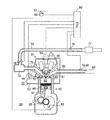
図1に本発明の第1実施形態の限界電流式センサの1つが示されている。図1の限界電流式センサは、2セルタイプの限界電流式センサである。図1において、10は限界電流式センサ、11Aは第1固体電解質層、11Bは第2固体電解質層、12Aは第1アルミナ層、12Bは第2アルミナ層、12Cは第3アルミナ層、12Dは第4アルミナ層、12Eは第5アルミナ層、12Fは第6アルミナ層、13は拡散律速層、14はヒータ、15はポンプセル、15Aは第1ポンプ電極、15Bは第2ポンプ電極、15Cはポンプセル電圧源、16はセンサセル、16Aは第1センサ電極、16Bは第2センサ電極、16Cはセンサセル電圧源、17Aは第1大気導入路、17Bは第2大気導入路、18は内部空間をそれぞれ示している。
<Configuration of 2-cell type limiting current sensor>
FIG. 1 shows one of the limiting current type sensors according to the first embodiment of the present invention. The limiting current type sensor of FIG. 1 is a two-cell type limiting current type sensor. In FIG. 1, 10 is a limiting current sensor, 11A is a first solid electrolyte layer, 11B is a second solid electrolyte layer, 12A is a first alumina layer, 12B is a second alumina layer, 12C is a third alumina layer, and 12D is 4th alumina layer, 12E is 5th alumina layer, 12F is 6th alumina layer, 13 is diffusion control layer, 14 is heater, 15 is pump cell, 15A is 1st pump electrode, 15B is 2nd pump electrode, 15C is pump cell Voltage source, 16 is a sensor cell, 16A is a first sensor electrode, 16B is a second sensor electrode, 16C is a sensor cell voltage source, 17A is a first atmosphere introduction path, 17B is a second atmosphere introduction path, and 18 is an internal space. ing.
固体電解質層11A、11Bは、ジルコニア等からなる層であり、酸素イオン伝導性を有する。アルミナ層12A〜12Fは、アルミナからなる層である。拡散律速層13は、多孔質の層であり、排気を通すことができる。センサ10では、各層は、図1において下方から、第6アルミナ層12F、第5アルミナ層12E、第4アルミナ層12D、第2固体電解質層11B、拡散律速層13および第3アルミナ層12C、第1固体電解質層11A、第2アルミナ層12B、第1アルミナ層12Aの順で積層されている。ヒータ14は、第5アルミナ層12Eと第6アルミナ層12Fとの間に配置されている。
The
第1大気導入路17Aは、第1アルミナ層12Aと第2アルミナ層12Bと第1固体電解質層11Aとによって形成された空間であり、その一部は大気に開放されている。第2大気導入路17Bは、第2固体電解質層11Bと第4アルミナ層12Dと第5アルミナ層12Eとによって形成された空間であり、その一部は大気に開放されている。内部空間18は、第1固体電解質層11Aと第2固体電解質層12Bと拡散律速層13と第3アルミナ層12Cとによって形成された空間であり、その一部は拡散律速層13を介してセンサ外部に連通している。
The first
<ポンプセルの構成>
第1ポンプ電極15Aおよび第2ポンプ電極15Bは、白金もしくはロジウム等の白金族元素またはその合金からなる電極である。第1ポンプ電極15Aは、第2固体電解質層11Bの一方の側の壁面(すなわち、内部空間18を形成する第2固体電解質層11Bの壁面)に配置され、第2ポンプ電極15Bは、第2固体電解質層11Bの他方の側の壁面(すなわち、第2大気導入路17Bを形成する第2固体電解質層11Bの壁面)に配置されている。これら電極15A、15Bと第2固体電解質層11Bとは、ポンプセル15を構成している。センサ10は、ポンプセル15(具体的には、第1ポンプ電極15Aと第2ポンプ電極15Bとの間)にポンプセル電圧源15Cから電圧を印加可能に構成されている。なお、第1ポンプ電極15Aは陰極側の電極であり、第2ポンプ電極15Bは陽極側の電極である。
<Configuration of pump cell>
The
<ポンプセルの機能>
ポンプセル15に電圧が印加されると、内部空間18内の酸素が第1ポンプ電極15Aに接触したときに、この酸素が第1ポンプ電極15A上で酸素イオンとなり、この酸素イオンが第2固体電解質層11Bの内部を第2ポンプ電極15Bに向かって移動する。このとき、第1ポンプ電極15Aと第2ポンプ電極15Bとの間には、第2固体電解質層11Bの内部を移動した酸素イオン量に比例した電流が流れる。そして、酸素イオンが第2ポンプ電極15Bに達すると、酸素イオンは第2ポンプ電極15Bにおいて酸素となって第2大気導入路17Bに放出される。つまり、ポンプセル15は、排気中の酸素を排気からポンピングによって大気に放出し、排気中の酸素濃度を低下させることができる。このポンプセル15のポンピング能力は、ポンプセル電圧源15Cから当該ポンプセル15に印加される電圧が高いほど高い。
<Pump cell function>
When a voltage is applied to the
<センサセルの構成>
第1センサ電極16Aおよび第2センサ電極16Bは、白金もしくはロジウム等の白金族元素またはその合金からなる電極である。第1センサ電極16Aは、第1固体電解質層11Aの一方の側の壁面(すなわち、内部空間18を形成する第1固体電解質層11Aの壁面)に配置され、第2センサ電極16Bは、第1固体電解質層11Aの他方の側の壁面(すなわち、第1大気導入路17Aを形成する第1固体電解質層11Aの壁面)に配置されている。これら電極16A、16Bと第1固体電解質層11Aとは、センサセル16を構成している。センサ10は、センサセル16(具体的には、第1センサ電極16Aと第2センサ電極16Bとの間)にセンサセル電圧源16Cから電圧を印加可能に構成されている。なお、第1センサ電極16Aは陰極側の電極であり、第2センサ電極16Bは陽極側の電極である。
<Configuration of sensor cell>
The
<センサセルの機能>
センサセル16に電圧が印加されると、内部空間18内のSOxが第1センサ電極16Aに接触したときに、このSOxが第1センサ電極16A上で分解され、SOxの酸素が酸素イオンとなり、この酸素イオンが第1固体電解質層11Aの内部を第2センサ電極16Bに向かって移動する。このとき、第1センサ電極16Aと第2センサ電極16Bとの間には、第1固体電解質層11Aの内部を移動した酸素イオン量に比例した電流が流れる。そして、酸素イオンが第2センサ電極16Bに達すると、酸素イオンは第2センサ電極16Bにおいて酸素となって第1大気導入路17Aに放出される。
<Function of sensor cell>
When a voltage is applied to the
<2セルタイプ限界電流式センサの出力特性>
ところで、本願の発明者らの研究により、2セルタイプの限界電流式センサへの印加電圧(具体的には、センサセル電圧源16Cからセンサセル16への印加電圧)を所定電圧から低下させることによって、排気中のSOx濃度に対応する電流をこの限界電流式センサから得られることが新たに判明した。次に、このことについて説明する。なお、以下の説明において、出力電流とはセンサセル16から出力される電流である。
<Output characteristics of 2-cell type limiting current sensor>
By the way, according to the research of the inventors of the present application, by reducing the applied voltage to the two-cell type limit current type sensor (specifically, the applied voltage from the sensor
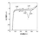
図2に、印加電圧を0.1Vから1.0Vまで徐々に上昇させ、その後、1.0Vから0.1Vまで徐々に低下させた場合の出力電流の変化が示されている。図2の横軸は印加電圧であり、図2の縦軸は出力電流である。なお、このように印加電圧を変化させている間、ポンプセル15には、内部空間18内の排気中の酸素濃度を零(または、略零)にする電圧が印加されている。
FIG. 2 shows changes in the output current when the applied voltage is gradually increased from 0.1 V to 1.0 V and then gradually decreased from 1.0 V to 0.1 V. The horizontal axis in FIG. 2 is the applied voltage, and the vertical axis in FIG. 2 is the output current. While the applied voltage is changed in this way, a voltage that makes the oxygen concentration in the exhaust gas in the
図2において、実線LU0は、排気中にSOxが含まれていない(すなわち、排気中のSOx濃度が零である)場合において印加電圧を0.1Vから1.0Vまで上昇させたときの出力電流の変化を示し、実線LD0は、同じく排気中にSOxが含まれていない場合において印加電圧を1.0Vから0.1Vまで低下させたときの出力電流の変化を示している。図2において、一点鎖線LU1は、排気中にSOxが含まれている場合において印加電圧を0.1Vから1.0Vまで上昇させたときの出力電流の変化を示し、一点鎖線LD1は、同じく排気中にSOxが含まれている場合において印加電圧を1.0Vから0.1Vまで低下させたときの出力電流の変化を示している。 In FIG. 2, a solid line LU0 indicates an output current when the applied voltage is increased from 0.1 V to 1.0 V when SOx is not included in the exhaust (that is, when the SOx concentration in the exhaust is zero). The solid line LD0 indicates the change in the output current when the applied voltage is decreased from 1.0 V to 0.1 V when SOx is not included in the exhaust gas. In FIG. 2, an alternate long and short dash line LU1 indicates a change in output current when the applied voltage is increased from 0.1 V to 1.0 V when SOx is included in the exhaust, and an alternate long and short dash line LD1 The graph shows changes in the output current when the applied voltage is decreased from 1.0 V to 0.1 V when SOx is included therein.
排気中にSOxが含まれていない場合、印加電圧が0.1Vから約0.2Vまで上昇されると、図2の実線LU0で示されているように、出力電流が約4μAまで急激に上昇する。そして、印加電圧が約0.2Vから約0.85Vまで上昇する間は、出力電流が約4μAで略一定である。そして、印加電圧が約0.85Vを上回ると、出力電流が上昇し始める。そして、印加電圧が約0.85Vから1.0Vまで上昇される間、出力電流は徐々に上昇し、印加電圧が1.0Vに達したときに、出力電流が約7μAに達する。 When SOx is not included in the exhaust, when the applied voltage is increased from 0.1 V to about 0.2 V, the output current increases rapidly to about 4 μA, as shown by the solid line LU0 in FIG. To do. Then, while the applied voltage rises from about 0.2 V to about 0.85 V, the output current is approximately constant at about 4 μA. When the applied voltage exceeds about 0.85 V, the output current starts to increase. The output current gradually increases while the applied voltage is raised from about 0.85 V to 1.0 V. When the applied voltage reaches 1.0 V, the output current reaches about 7 μA.
そして、その後、印加電圧が1.0Vから0.4Vに向けて徐々に低下されると、図2の実線LD0で示されているように、出力電流が約7μAから徐々に低下し、印加電圧が約0.85Vを下回ってから0.4Vに達するまでの間は、出力電流が約3.5μAで略一定である。 After that, when the applied voltage is gradually decreased from 1.0 V to 0.4 V, the output current gradually decreases from about 7 μA as shown by the solid line LD0 in FIG. The output current is substantially constant at about 3.5 μA until the voltage reaches about 0.4 V after the voltage drops below about 0.85 V.
一方、排気中にSOxが含まれている場合、印加電圧が0.1Vから約0.2Vまで上昇されると、図2の一点鎖線LU1で示されているように、出力電流が約0.4μAまで急激に上昇する。そして、印加電圧が約0.2Vから約0.6Vまで上昇する間は、出力電流が約4μAで略一定である。そして、印加電圧が約0.6Vを上回ると、出力電流が上昇し始める。そして、印加電圧が約0.6Vから1.0Vまで上昇される間、出力電流は徐々に上昇し、印加電圧が1.0Vに達したときに約7μAに達する。 On the other hand, when SOx is contained in the exhaust gas, when the applied voltage is increased from 0.1 V to about 0.2 V, the output current is about 0. 0 as shown by the one-dot chain line LU1 in FIG. It rises rapidly to 4 μA. While the applied voltage rises from about 0.2 V to about 0.6 V, the output current is about 4 μA and is substantially constant. When the applied voltage exceeds about 0.6 V, the output current starts to increase. The output current gradually increases while the applied voltage is raised from about 0.6 V to 1.0 V, and reaches about 7 μA when the applied voltage reaches 1.0 V.
そして、その後、印加電圧が1.0Vから0.4Vに向けて徐々に低下されると、図2の一点鎖線LD1で示されているように、出力電流が約7μAから徐々に低下し、印加電圧が約0.8Vを下回ってから約0.7Vに達するまでの間に、出力電流が急激に低下して当該出力電流の流れる方向が逆転し、約−5μAに達する。そして、印加電圧がさらに約0.7Vから0.4Vまで低下される間に、出力電流が急激に上昇して当該出力電流の流れる方向が元の方向に戻り、印加電圧が0.4Vに達すると、出力電流が約3.5μAとなる。 Then, when the applied voltage is gradually decreased from 1.0 V to 0.4 V, the output current gradually decreases from about 7 μA as shown by the one-dot chain line LD1 in FIG. Between the time when the voltage drops below about 0.8V and the time when the voltage reaches about 0.7V, the output current rapidly decreases and the direction in which the output current flows is reversed to reach about −5 μA. Then, while the applied voltage is further reduced from about 0.7V to 0.4V, the output current rapidly rises, the direction in which the output current flows returns to the original direction, and the applied voltage reaches 0.4V. Then, the output current becomes about 3.5 μA.
したがって、排気中にSOxが含まれている場合、印加電圧が0.4Vから0.8Vに上昇され、その後、印加電圧が0.8Vから0.4Vに低下されると、印加電圧が低下される間に出力電流が急激に低下した後に急激に上昇する。つまり、印加電圧が0.8Vから0.4Vまで低下されると、出力電流は最小値(すなわち、ピーク値)のある変化を示す。ここで、印加電圧が約0.7Vに達したときに、出力電流がピーク値となる。 Therefore, when SOx is included in the exhaust gas, the applied voltage is increased from 0.4 V to 0.8 V, and then the applied voltage is decreased when the applied voltage is decreased from 0.8 V to 0.4 V. During this period, the output current suddenly decreases and then increases rapidly. That is, when the applied voltage is decreased from 0.8 V to 0.4 V, the output current shows a change with a minimum value (that is, a peak value). Here, when the applied voltage reaches about 0.7 V, the output current has a peak value.
なお、排気中にSOxが含まれている場合において印加電圧が約0.6Vを上回ってから1.0Vに達するまでの出力電流は、排気中にSOxが含まれていない場合において印加電圧が約0.6Vを上回ってから1.0Vに達するまでの出力電流よりも大きい。 When SOx is included in the exhaust gas, the output current from when the applied voltage exceeds approximately 0.6 V to 1.0 V is approximately equal to the applied voltage when SOx is not included in the exhaust gas. It is larger than the output current from reaching 0.6V after exceeding 0.6V.
<第1実施形態の2セルタイプの限界電流式センサの利点>
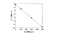
そして、本願の発明者らの研究により、2セルタイプの限界電流式センサにおいて、上述したように印加電圧を0.8Vから0.4Vまで低下させたときの出力電流のピーク値とSOx濃度との間には、図3に示されている関係があることが判明した。つまり、参照電流(すなわち、印加電圧が0.8Vに達した時点の出力電流)と前記ピーク値との差が大きいほど、排気中のSOx濃度が高いことが判明した。したがって、第1実施形態の2セルタイプの限界電流式センサによれば、前記ピーク値を用いてSOx濃度を算出(すなわち、検出)することができる。
<Advantages of the 2-cell type limiting current sensor of the first embodiment>
According to the research of the inventors of the present application, the peak value of the output current and the SOx concentration when the applied voltage is reduced from 0.8 V to 0.4 V as described above in the two-cell type limiting current sensor, It was found that there is a relationship shown in FIG. That is, it has been found that the SOx concentration in the exhaust gas is higher as the difference between the reference current (that is, the output current when the applied voltage reaches 0.8 V) and the peak value is larger. Therefore, according to the two-cell type limiting current sensor of the first embodiment, the SOx concentration can be calculated (that is, detected) using the peak value.
<1セルタイプ限界電流式センサの構成>
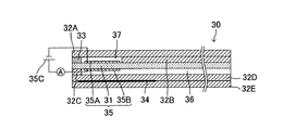
図4に本発明の第1実施形態の限界電流式センサのさらに1つが示されている。図4の限界電流式センサは、1セルタイプの限界電流式センサである。図4において、30は限界電流式センサ、31は固体電解質層、32Aは第1アルミナ層、32Bは第2アルミナ層、32Cは第3アルミナ層、32Dは第4アルミナ層、32Eは第5アルミナ層、33は拡散律速層、34はヒータ、35はセンサセル、35Aは第1センサ電極、35Bは第2センサ電極、35Cはセンサセル電圧源、36は大気導入路、37は内部空間をそれぞれ示している。
<Configuration of 1-cell type limiting current sensor>
FIG. 4 shows another one of the limiting current type sensors according to the first embodiment of the present invention. The limiting current type sensor of FIG. 4 is a one-cell type limiting current type sensor. In FIG. 4, 30 is a limiting current type sensor, 31 is a solid electrolyte layer, 32A is a first alumina layer, 32B is a second alumina layer, 32C is a third alumina layer, 32D is a fourth alumina layer, and 32E is a fifth alumina. Layer, 33 is a diffusion-controlled layer, 34 is a heater, 35 is a sensor cell, 35A is a first sensor electrode, 35B is a second sensor electrode, 35C is a sensor cell voltage source, 36 is an air introduction path, and 37 is an internal space. Yes.
固体電解質層31は、ジルコニア等からなる層であり、酸素イオン伝導性を有する。アルミナ層32A〜32Eは、アルミナからなる層である。拡散律速層33は、多孔質の層であり、排気を通すことができる。センサ30では、各層は、図4において下方から、第5アルミナ層32E、第4アルミナ層32D、第3アルミナ層32C、固体電解質層31、拡散律速層33および第2アルミナ層32B、第1アルミナ層32Aの順で積層されている。ヒータ34は、第4アルミナ層32Dと第5アルミナ層32Eとの間に配置されている。
The
大気導入路36は、固体電解質層31と第3アルミナ層32Cと第4アルミナ層32Dとによって形成された空間であり、その一部は大気に開放されている。内部空間37は、第1アルミナ層32Aと固体電解質層31と拡散律速層33と第2アルミナ層32Bとによって形成された空間であり、その一部は拡散律速層33を介してセンサ外部に連通している。
The
<センサセルの構成>
第1センサ電極35Aおよび第2センサ電極35Bは、白金もしくはロジウム等の白金族元素またはその合金からなる電極である。第1センサ電極35Aは、固体電解質層31の一方の側の壁面(すなわち、内部空間37を形成する固体電解質層31の壁面)に配置され、第2センサ電極35Bは、固体電解質層31の他方の側の壁面(すなわち、大気導入路36を形成する固体電解質層31の壁面)に配置されている。これら電極35A、35Bと固体電解質層31とは、センサセル35を構成している。センサ30は、センサセル35(具体的には、第1センサ電極35Aと第2センサ電極35Bとの間)にセンサセル電圧源35Cから電圧を印加可能に構成されている。なお、第1センサ電極35Aは陰極側の電極であり、第2センサ電極35Bは陽極側の電極である。
<Configuration of sensor cell>
The
<センサセルの機能>
センサセル35に電圧が印加されると、内部空間37内のSOxが第1センサ電極35Aに接触したときに、このSOxが第1センサ電極35A上で分解され、SOxの酸素が酸素イオンとなり、この酸素イオンが固体電解質層31の内部を第2センサ電極35Bに向かって移動する。このとき、第1センサ電極35Aと第2センサ電極35Bとの間には、固体電解質層31の内部を移動した酸素イオン量に比例した電流が流れる。そして、酸素イオンが第2センサ電極35Bに達すると、酸素イオンは第2センサ電極35Bにおいて酸素となって大気導入路36に放出される。
<Function of sensor cell>
When a voltage is applied to the
<1セルタイプ限界電流式センサの出力特性>
ところで、本願の発明者らの研究により、2セルタイプの限界電流式センサと同様に、1セルタイプの限界電流式センサへの印加電圧(具体的には、センサセル電圧源35Cからセンサセル35への印加電圧)を所定電圧から低下させることによって、排気中のSOx濃度に対応する電流をこの限界電流式センサからも得られることが判明した。次に、このことについて説明する。なお、以下の説明において、出力電流とはセンサセル35から出力される電流であり、当該排気中の酸素濃度は1%で一定である。
<Output characteristics of 1-cell type limiting current sensor>
By the way, according to the research of the inventors of the present application, the voltage applied to the one-cell type limiting current type sensor (specifically, from the sensor
図5に、印加電圧を0.1Vから1.0Vまで徐々に上昇させ、その後、1.0Vから0.1Vまで徐々に低下させた場合の出力電流の変化が示されている。図5の横軸は印加電圧であり、図5の縦軸は出力電流である。 FIG. 5 shows changes in the output current when the applied voltage is gradually increased from 0.1 V to 1.0 V and then gradually decreased from 1.0 V to 0.1 V. The horizontal axis in FIG. 5 is the applied voltage, and the vertical axis in FIG. 5 is the output current.
図5において、一点鎖線LU1は、排気中にSOxが含まれている場合において印加電圧を0.1Vから1.0Vまで上昇させたときの出力電流の変化を示し、一点鎖線LD1は、同じく排気中にSOxが含まれている場合において印加電圧を1.0Vから0.1Vまで低下させたときの出力電流の変化を示している。 In FIG. 5, an alternate long and short dash line LU1 indicates a change in output current when the applied voltage is increased from 0.1 V to 1.0 V when SOx is included in the exhaust, and an alternate long and short dash line LD1 The graph shows changes in the output current when the applied voltage is decreased from 1.0 V to 0.1 V when SOx is included therein.
排気中にSOxが含まれている場合において印加電圧が0.1Vから約0.2Vまで上昇されると、図5の一点鎖線LU1で示されているように、出力電流が約100μAまで急激に上昇する。そして、印加電圧が約0.2Vから約0.6Vまで上昇する間は、出力電流が約100μAで略一定である。そして、印加電圧が約0.6Vを上回ると、出力電流が上昇し始める。そして、印加電圧が約0.6Vから1.0Vまで上昇される間、出力電流は若干ではあるが徐々に上昇し、印加電圧が1.0Vに達したときに約105μAに達する。 When SOx is included in the exhaust gas, when the applied voltage is increased from 0.1 V to about 0.2 V, the output current suddenly increases to about 100 μA as shown by the one-dot chain line LU1 in FIG. To rise. Then, while the applied voltage rises from about 0.2 V to about 0.6 V, the output current is approximately constant at about 100 μA. When the applied voltage exceeds about 0.6 V, the output current starts to increase. Then, while the applied voltage is raised from about 0.6 V to 1.0 V, the output current gradually increases slightly, and reaches about 105 μA when the applied voltage reaches 1.0 V.
そして、その後、印加電圧が1.0Vから0.4Vに向けて徐々に低下されると、図5の一点鎖線LD1で示されているように、出力電流が約105μAから徐々に低下し、印加電圧が約0.8Vを下回ってから約0.7Vに達するまでの間に、出力電流が急激に低下し、約80μAに達する。そして、印加電圧が約0.7Vから0.4Vまで低下される間に、出力電流が急激に上昇し、印加電圧が0.4Vに達すると、出力電流が約100μAとなる。 After that, when the applied voltage is gradually decreased from 1.0 V to 0.4 V, the output current is gradually decreased from about 105 μA as shown by the one-dot chain line LD1 in FIG. Between the time when the voltage drops below about 0.8 V and the time when the voltage reaches about 0.7 V, the output current rapidly decreases and reaches about 80 μA. Then, while the applied voltage is lowered from about 0.7 V to 0.4 V, the output current rises rapidly, and when the applied voltage reaches 0.4 V, the output current becomes about 100 μA.
したがって、排気中にSOxが含まれている場合、印加電圧が0.4Vから0.8Vに上昇され、その後、印加電圧が0.8Vから0.4Vに低下されると、印加電圧が低下される間に出力電流が急激に低下した後に急激に上昇する。つまり、印加電圧が0.8Vから0.4Vまで低下されると、出力電流は最小値(すなわち、ピーク値)のある変化を示す。ここで、印加電圧が約0.7Vに達したときに、出力電流がピーク値となる。 Therefore, when SOx is included in the exhaust gas, the applied voltage is increased from 0.4 V to 0.8 V, and then the applied voltage is decreased when the applied voltage is decreased from 0.8 V to 0.4 V. During this period, the output current suddenly decreases and then increases rapidly. That is, when the applied voltage is decreased from 0.8 V to 0.4 V, the output current shows a change with a minimum value (that is, a peak value). Here, when the applied voltage reaches about 0.7 V, the output current has a peak value.
<第1実施形態の1セルタイプの限界電流式センサの利点>
そして、本願の発明者らの研究により、1セルタイプの限界電流式センサにおいて、上述したように印加電圧を0.8Vから0.4Vまで低下させたときの出力電流のピーク値とSOx濃度との間にも、図3に示されている関係と同様の関係があることが判明した。つまり、参照電流(すなわち、印加電圧が0.8Vに達した時点の出力電流)と前記ピーク値との差が大きいほど、排気中のSOx濃度が高いことが判明した。したがって、第1実施形態の1セルタイプの限界電流式センサによれば、前記ピーク値を用いてSOx濃度を算出(すなわち、検出)することができる。
<Advantages of 1-cell type limiting current type sensor according to the first embodiment>
According to the research of the inventors of the present application, the peak value of the output current and the SOx concentration when the applied voltage is reduced from 0.8 V to 0.4 V as described above in the one-cell type limiting current type sensor, It was also found that there is a relationship similar to that shown in FIG. That is, it has been found that the SOx concentration in the exhaust gas is higher as the difference between the reference current (that is, the output current when the applied voltage reaches 0.8 V) and the peak value is larger. Therefore, according to the one-cell type limiting current sensor of the first embodiment, the SOx concentration can be calculated (that is, detected) using the peak value.
<第1実施形態のSOx濃度検出装置>
図6に、図1の限界電流式センサ10または図4の限界電流式センサ30を有するSOx濃度検出装置を備えた内燃機関が示されている。図6の内燃機関は、火花点火式内燃機関(いわゆるガソリンエンジン)である。しかしながら、本発明は、圧縮自着火式内燃機関(いわゆるディーゼルエンジン)にも適用可能である。また、図6の内燃機関は、大部分の機関運転領域において、空燃比が理論空燃比(ストイキ)にて運転される。
<SOx concentration detection apparatus of the first embodiment>
FIG. 6 shows an internal combustion engine equipped with a SOx concentration detection device having the limiting
<内燃機関の構成>
図6において、10または30は図1または図4の限界電流式センサ、50は内燃機関の本体、51はシリンダヘッド、52はシリンダブロック、53は燃焼室、54は燃料噴射弁、55は点火プラグ、56は燃料ポンプ、57は燃料供給管、60はピストン、61はコネクティングロッド、62はクランクシャフト、63はクランク角度センサ、70は吸気弁、71は吸気ポート、72は吸気マニホルド、73はサージタンク、74はスロットル弁、75は吸気管、76はエアフローメータ、77はエアフィルタ、80は排気弁、81は排気ポート、82は排気マニホルド、83は排気管、90は電子制御装置(ECU)、91はアクセルペダル、92はアクセルペダル踏込量センサをそれぞれ示している。
<Configuration of internal combustion engine>
6, 10 or 30 is the limiting current type sensor of FIG. 1 or FIG. 4, 50 is the body of the internal combustion engine, 51 is the cylinder head, 52 is the cylinder block, 53 is the combustion chamber, 54 is the fuel injection valve, and 55 is the ignition. Plug, 56, fuel pump, 57, fuel supply pipe, 60, piston, 61, connecting rod, 62, crankshaft, 63, crank angle sensor, 70, intake valve, 71, intake port, 72, intake manifold, 73 Surge tank, 74 throttle valve, 75 intake pipe, 76 air flow meter, 77 air filter, 80 exhaust valve, 81 exhaust port, 82 exhaust manifold, 83 exhaust pipe, 90 electronic control unit (ECU) ), 91 denotes an accelerator pedal, and 92 denotes an accelerator pedal depression amount sensor.
<ECUの構成・機能>
燃料噴射弁54、点火プラグ55、スロットル弁74、クランク角度センサ63、エアフローメータ76、アクセルペダル踏込量センサ92、および、限界電流式センサ10、30は、ECU90に電気的に接続されている。ECU90は、燃料噴射弁54、点火プラグ55、および、スロットル弁74を動作させるための信号をこれらに送信する。また、ECU90は、クランク角度センサ63、エアフローメータ76、および、アクセルペダル踏込量センサ92から信号を受信する。クランク角度センサ63からは、クランクシャフト62の回転速度に対応する信号が出力される。ECU90は、クランク角度センサ63から受信した信号に基づいて機関回転数を算出する。エアフローメータ76からは、そこを通過する空気の流量(ひいては、燃焼室53に吸入される空気の流量)に対応する信号が出力される。ECU90は、エアフローメータ76から受信した信号に基づいて吸入空気量を算出する。アクセルペダル踏込量センサ92からは、アクセルペダル91の踏込量に対応する信号が出力される。ECU90は、アクセルペダル踏込量センサ92から受信した信号に基づいて機関負荷を算出する。
<Configuration and function of ECU>
The
<限界電流式センサ>
限界電流式センサ10、30は、排気管83に取り付けられている。したがって、限界電流式センサ10、30の検出対象となるガス(すなわち、被検ガス)は、燃焼室53から排出される排気である。限界電流式センサ10、30からは、そこに到来する排気中のSOx濃度に対応する電流が出力される。ECU90は、限界電流式センサ10、30から受信した電流に基づいてSOx濃度を算出する(この算出方法の詳細は後述する)。
<Limit current sensor>
The limit
<第1実施形態のSOx濃度検出>
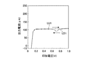
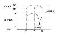
第1実施形態のSOx濃度検出について図7を参照しつつ説明する。第1実施形態では、印加電圧が定常的に0.4Vに維持されている(図7の時刻T0以前の期間参照)。すなわち、センサに定常的に0.4Vが印加されている。そして、第1実施形態のSOx濃度検出では、印加電圧が0.4Vから0.8Vまで上昇され(図7の時刻T0から時刻T1までの期間参照)、その後、印加電圧が0.8Vから0.4Vまで低下される(図7の時刻T1から時刻T2までの期間参照)。このとき、ECUは、印加電圧が0.8Vから0.4Vまで低下される間に当該ECUに入力された出力電流のピーク値と参照電流とを用いてSOx濃度を算出(すなわち、検出)する。このとき、参照電流とピーク値との差が大きいほど、算出されるSOx濃度は高い。
<SOx concentration detection in the first embodiment>
The SOx concentration detection of the first embodiment will be described with reference to FIG. In the first embodiment, the applied voltage is constantly maintained at 0.4 V (see the period before time T0 in FIG. 7). That is, 0.4 V is constantly applied to the sensor. In the SOx concentration detection according to the first embodiment, the applied voltage is increased from 0.4 V to 0.8 V (see the period from time T0 to time T1 in FIG. 7), and then the applied voltage is changed from 0.8 V to 0. The voltage is reduced to 4 V (see the period from time T1 to time T2 in FIG. 7). At this time, the ECU calculates (that is, detects) the SOx concentration using the peak value of the output current input to the ECU and the reference current while the applied voltage is decreased from 0.8 V to 0.4 V. . At this time, the greater the difference between the reference current and the peak value, the higher the calculated SOx concentration.
なお、ピーク値と参照電流との差(以下「電流差」)を用いてSOx濃度を算出する場合、たとえば、電流差に対応するSOx濃度が電流差毎に予め実験等によって求められ、これら求められたSOx濃度が電流差の関数のマップの形でECUに記憶され、SOx濃度の検出中に算出される電流差に対応するSOx濃度をマップから読み出すことによって、SOx濃度が算出される。 When calculating the SOx concentration using the difference between the peak value and the reference current (hereinafter referred to as “current difference”), for example, the SOx concentration corresponding to the current difference is obtained for each current difference in advance by experiments or the like. The obtained SOx concentration is stored in the ECU in the form of a current difference function map, and the SOx concentration corresponding to the current difference calculated during the detection of the SOx concentration is read out from the map to calculate the SOx concentration.
<第1実施形態のSOx濃度検出装置の利点>
第1実施形態のSOx濃度検出装置によれば、排気中のSOx濃度を検出することができる。すなわち、印加電圧が一定の電圧(たとえば、0.4V)に維持されているときの出力電流に占めるSOxの影響、または、印加電圧が上昇されたときの出力電流に占めるSOxの影響が、同出力電流に占める他の成分(たとえば、O2やNOx)の影響に比べて小さいが、印加電圧が所定電圧(たとえば、0.8)から低下されたときの出力電流に占めるSOxの影響が、同出力電流に占める他の成分の影響に比べて大きいという知見を本願の発明者らが得ており、このため、第1実施形態のSOx濃度検出装置によれば、SOx濃度を精度良く検出することができるのである。
<Advantages of the SOx concentration detection apparatus of the first embodiment>
According to the SOx concentration detection apparatus of the first embodiment, the SOx concentration in exhaust gas can be detected. That is, the effect of SOx on the output current when the applied voltage is maintained at a constant voltage (for example, 0.4 V) or the effect of SOx on the output current when the applied voltage is increased are the same. The effect of SOx on the output current when the applied voltage is reduced from a predetermined voltage (eg, 0.8) is small compared to the effect of other components (eg, O 2 and NOx) on the output current. The inventors of the present application have obtained the knowledge that it is larger than the influence of other components in the output current. Therefore, according to the SOx concentration detection device of the first embodiment, the SOx concentration can be detected with high accuracy. It can be done.
また、ピーク値は、印加電圧の低下中の出力電流のうち、SOx濃度が零である場合の出力電流から最も大きく異なる出力電流である。したがって、ピーク値は、SOx濃度に精度良く対応する出力電流であると言える。このため、SOx濃度検出用の出力電流としてピーク値を用いることによって、SOx濃度をより精度良く検出することができる。 The peak value is an output current that is most different from the output current when the SOx concentration is zero among the output currents during the decrease of the applied voltage. Therefore, it can be said that the peak value is an output current that accurately corresponds to the SOx concentration. Therefore, the SOx concentration can be detected with higher accuracy by using the peak value as the output current for detecting the SOx concentration.
また、第1実施形態では、印加電圧の低下開始前にセンサに印加させておく電圧は0.4Vである。したがって、この電圧は、印加電圧の低下開始時点の印加電圧である0.8Vよりも低い。このため、第1実施形態によれば、印加電圧の低下開始前にセンサに印加させておく電圧が0.8Vである場合に比べて、SOx濃度検出に消費される電力を少なくすることができる。 In the first embodiment, the voltage applied to the sensor before the applied voltage starts to decrease is 0.4V. Therefore, this voltage is lower than 0.8 V that is the applied voltage at the start of the decrease of the applied voltage. For this reason, according to the first embodiment, it is possible to reduce the power consumed for SOx concentration detection, compared to the case where the voltage applied to the sensor before the start of the decrease in the applied voltage is 0.8V. .
<第1実施形態の適用範囲>
なお、第1実施形態のSOx濃度検出において、印加電圧の上昇開始時点の印加電圧(すなわち、センサに定常的に印加しておく印加電圧)は、0.4Vに限定されず、印加電圧の上昇後に印加電圧を低下させたときにピーク値を持つ出力電流の変化を発生させる電圧であればよく、たとえば、0.6V以下であればよく、好ましくは、0.4Vである。
<Applicable scope of the first embodiment>
In the SOx concentration detection according to the first embodiment, the applied voltage at the start of increasing the applied voltage (that is, the applied voltage that is steadily applied to the sensor) is not limited to 0.4 V, and the applied voltage increases. Any voltage may be used as long as it causes a change in output current having a peak value when the applied voltage is lowered later. For example, the voltage may be 0.6 V or less, and preferably 0.4 V.
また、印加電圧の上昇終了時点の印加電圧は、0.8Vに限定されず、印加電圧の上昇後に印加電圧を低下させたときにピーク値を持つ出力電流の変化を発生させる電圧、または、出力安定電圧範囲(すなわち、SOx濃度が零である場合に、印加電圧に依らず出力電流が略一定である範囲であって、たとえば、0.2V〜0.8Vの範囲)の最大電圧以上の電圧であればよく、たとえば、0.8V以上であればよい。 In addition, the applied voltage at the end of the increase in the applied voltage is not limited to 0.8 V, and a voltage that generates a change in output current having a peak value when the applied voltage is lowered after the applied voltage is increased, or an output A voltage equal to or higher than the maximum voltage in the stable voltage range (that is, in the range where the output current is substantially constant regardless of the applied voltage when the SOx concentration is zero, for example, in the range of 0.2 V to 0.8 V). For example, it may be 0.8 V or more.
また、印加電圧の低下終了時点の印加電圧は、0.4Vに限定されず、ピーク値に対応する印加電圧以下であればよく、たとえば、0.7V以下であればよく、好ましくは、0.4Vである。したがって、印加電圧の上昇開始時点の印加電圧は、印加電圧の低下終了時点の印加電圧と同じであっても異なっていてもよい。 Further, the applied voltage at the end of the decrease in the applied voltage is not limited to 0.4 V, and may be equal to or lower than the applied voltage corresponding to the peak value, for example, 0.7 V or lower. 4V. Therefore, the applied voltage at the start of application voltage increase may be the same as or different from the applied voltage at the end of decrease in applied voltage.
また、第1実施形態のSOx濃度検出では、ピーク値が用いられるが、これに代えて、印加電圧が0.8Vから0.4Vまで低下される間に出力電流が急激に低下する範囲または急激に上昇する範囲の出力電流が用いられてもよい。 In the SOx concentration detection of the first embodiment, a peak value is used. Instead, a range in which the output current rapidly decreases while the applied voltage is decreased from 0.8 V to 0.4 V or abruptly. An output current in a range that rises rapidly may be used.
<参照電流>
なお、センサの内部空間に流入する排気中の酸素濃度が印加電圧の低下中に変化する場合がある。この場合、印加電圧の低下に一定時間を要することを考慮すれば、印加電圧が0.8Vであるときの出力電流よりも、印加電圧が0.4Vであるときの出力電流のほうが、ピーク値の出力時点のセンサの内部空間内の排気中の酸素濃度をより正確に反映していると言える。そこで、第1実施形態のSOx濃度検出において、印加電圧が0.8Vから0.4Vまで低下される場合、前記参照電流に代えて、印加電圧が0.4Vに達した時点(または、その時点から所定時間経過後の出力電流)が参照電流として用いられてもよい。これによれば、排気中の酸素濃度が印加電圧の低下中に変化したとしても、SOx濃度を精度良く検出することができる。
<Reference current>
Note that the oxygen concentration in the exhaust gas flowing into the internal space of the sensor may change while the applied voltage is decreasing. In this case, considering that it takes a certain time to decrease the applied voltage, the output current when the applied voltage is 0.4 V is higher than the output current when the applied voltage is 0.8 V. It can be said that the oxygen concentration in the exhaust gas in the internal space of the sensor at the time of output is more accurately reflected. Therefore, in the SOx concentration detection of the first embodiment, when the applied voltage is reduced from 0.8 V to 0.4 V, when the applied voltage reaches 0.4 V (or at that time) instead of the reference current. Output current after a predetermined time has elapsed) may be used as the reference current. According to this, even if the oxygen concentration in the exhaust gas changes while the applied voltage is decreasing, the SOx concentration can be detected with high accuracy.
また、第1実施形態において、ピーク値と参照電流とを用いてSOx濃度を算出する代わりに、ピーク値と変換係数とを用いてSOx濃度を算出するようにしてもよい。このとき、ピーク値がマイナス方向に大きいほど、算出されるSOx濃度は高い。なお、変換係数とは、図3の関係に従ってピーク値をSOx濃度に変換する係数である。もちろん、ピーク値がプラスの値として出現する場合には、ピーク値がプラス方向に大きいほど、算出されるSOx濃度は高いことになる。 In the first embodiment, instead of calculating the SOx concentration using the peak value and the reference current, the SOx concentration may be calculated using the peak value and the conversion coefficient. At this time, the greater the peak value in the negative direction, the higher the calculated SOx concentration. The conversion coefficient is a coefficient for converting the peak value into the SOx concentration according to the relationship of FIG. Of course, when the peak value appears as a positive value, the calculated SOx concentration increases as the peak value increases in the positive direction.
<第1実施形態のスイープ速度>
第1実施形態のSOx濃度検出において、印加電圧の上昇速度または低下速度(スイープ速度)が速すぎると、印加電圧が低下されたとしても、ピーク値が出力されなかったり、SOx濃度に十分に対応するピーク値が出力されなかったりする可能性がある。そこで、第1実施形態のSOx濃度検出において、印加電圧が低下されたときにSOx濃度に十分に対応するピーク値が出力される印加電圧の上昇速度と低下速度とが選択されると好ましい。
<Sweep speed of the first embodiment>
In the SOx concentration detection of the first embodiment, if the applied voltage rises or falls (sweep speed) is too fast, even if the applied voltage is lowered, the peak value is not output, or the SOx concentration is sufficiently dealt with. The peak value to be output may not be output. Therefore, in the SOx concentration detection of the first embodiment, it is preferable to select an increase rate and a decrease rate of the applied voltage that outputs a peak value sufficiently corresponding to the SOx concentration when the applied voltage is decreased.
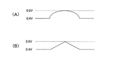
具体的には、図8(A)に示されているように、印加電圧の上昇速度が徐々に減少するように印加電圧が上昇された後、印加電圧の低下速度が徐々に増大するように印加電圧が低下されると好ましい。あるいは、図8(B)に示されているように、印加電圧の上昇速度が一定に維持されるように印加電圧が上昇された後、印加電圧の低下速度が一定に維持されるように印加電圧が低下されると好ましい。 Specifically, as shown in FIG. 8 (A), after the applied voltage is increased so that the applied voltage increases gradually, the applied voltage decreases gradually. It is preferable that the applied voltage is lowered. Alternatively, as shown in FIG. 8B, after the applied voltage is increased so that the applied voltage rise rate is maintained constant, the applied voltage is applied so that the applied voltage decrease rate is maintained constant. It is preferable if the voltage is lowered.
さらに具体的には、第1実施形態のSOx濃度検出において、印加電圧が0.4Vから0.8Vまで上昇された後、0.8Vから0.4Vまで低下されるまでの印加電圧の変化を周波数で表したとき、この周波数は、100Hz以下であることが好ましい。別の言い方をすると、印加電圧の上昇が開始されてから印加電圧の低下が終了されるまでの時間が0.005秒以上であることが好ましい。 More specifically, in the SOx concentration detection according to the first embodiment, the change in the applied voltage until the applied voltage is lowered from 0.8 V to 0.4 V after the applied voltage is raised from 0.4 V to 0.8 V. When expressed in terms of frequency, this frequency is preferably 100 Hz or less. In other words, it is preferable that the time from when the increase of the applied voltage is started to when the decrease of the applied voltage is completed is 0.005 seconds or more.
<SOx検出回路の構成1>
なお、内燃機関が図1の限界電流式センサ(2セルタイプ限界電流式センサ)を有する場合、SOx検出回路として、たとえば、図9(A)に示されている回路が採用される。図9(A)において、10は限界電流式センサ(すなわち、図1の限界電流式センサ)、14はヒータ、15はポンプセル、16はセンサセル、90はECU、91は印加電圧指令部、92はパラメータ算出部、93はヒータ制御部、94Pおよび94Sは印加電圧制御回路、95Pおよび95Sは出力電流検出回路をそれぞれ示している。
<
When the internal combustion engine has the limit current type sensor (2-cell type limit current type sensor) of FIG. 1, for example, the circuit shown in FIG. 9A is employed as the SOx detection circuit. In FIG. 9A, 10 is a limiting current type sensor (that is, the limiting current type sensor of FIG. 1), 14 is a heater, 15 is a pump cell, 16 is a sensor cell, 90 is an ECU, 91 is an applied voltage command unit, and 92 is A parameter calculation unit, 93 is a heater control unit, 94P and 94S are applied voltage control circuits, and 95P and 95S are output current detection circuits.
印加電圧指令部91、パラメータ算出部92、および、ヒータ制御部93は、ECU90の構成要素である。
The applied
印加電圧指令部91は、ポンプセル15への印加電圧に関する指令を印加電圧制御回路94Pに送信するとともに、センサセル16への印加電圧に関する指令を印加電圧制御回路94Sに送信する。
The applied
パラメータ算出部92は、ポンプセル出力電流に対応する信号を出力電流検出回路95Pから受信し、この受信した信号に基づいてポンプセル出力電流を算出する。さらに、パラメータ算出部92は、センサセル出力電流に対応する信号を出力電流検出回路95Sから受信し、この受信した信号に基づいてセンサセル出力電流を算出し、この算出した出力電流に基づいて排気中のSOx濃度を算出する。さらに、パラメータ算出部92は、出力電流検出回路95P、95Sから受信した信号に基づいてセンサ10内の回路のインピーダンスを算出し、この算出したインピーダンスに関する情報をヒータ制御部93に送信する。ヒータ制御部93は、パラメータ算出部92から受信したインピーダンスに関する情報に基づいてヒータ14を制御する制御信号をヒータ14に送信する。
The
印加電圧制御回路94Pは、印加電圧指令部91から受信した指令に基づいて(あるいは、印加電圧指令部91から受信した指令、および、出力電流検出回路95Pから提供されるポンプセル出力電流に対応する信号に基づいて)ポンプセル印加電圧を制御する。
The applied voltage control circuit 94P is based on the command received from the applied voltage command unit 91 (or the command corresponding to the command received from the applied
出力電流検出回路95Pは、ポンプセル出力電流を検出し、この検出した出力電流に対応する信号をパラメータ算出部92および印加電圧制御回路94Pに送信する。
The output
印加電圧制御回路94Sは、印加電圧指令部91から受信した指令に基づいて(あるいは、印加電圧指令部91から受信した指令、および、出力電流検出回路95Sから提供されるセンサセル出力電流に対応する信号に基づいて)センサセル印加電圧を制御する。
The applied
出力電流検出回路95Sは、センサセル出力電流を検出し、この検出した出力電流に対応する信号をパラメータ算出部92および印加電圧制御回路94Sに送信する。
The output
<SOx検出回路の構成2>
また、内燃機関が図4の限界電流式センサ(1セルタイプ限界電流式センサ)を有する場合のSOx検出回路として、たとえば、図9(B)に示されている回路が採用される。図9(B)において、30は限界電流式センサ(すなわち、図4の限界電流式センサ)、34はヒータ、35はセンサセル、90はECU、91は印加電圧指令部、92はパラメータ算出部、93はヒータ制御部、94は印加電圧制御回路、95は出力電流検出回路をそれぞれ示している。
<
Further, as the SOx detection circuit when the internal combustion engine has the limiting current type sensor (1-cell type limiting current type sensor) of FIG. 4, for example, the circuit shown in FIG. 9B is employed. In FIG. 9B, 30 is a limit current type sensor (that is, the limit current type sensor of FIG. 4), 34 is a heater, 35 is a sensor cell, 90 is an ECU, 91 is an applied voltage command unit, 92 is a parameter calculation unit,
印加電圧指令部91、パラメータ算出部92、および、ヒータ制御部93は、ECU90の構成要素である。
The applied
印加電圧指令部91は、センサセル35への印加電圧に関する指令を印加電圧制御回路94に送信する。
The applied
パラメータ算出部92は、センサセル出力電流に対応する信号を出力電流検出回路95から受信し、この受信した信号に基づいてセンサセル出力電流を算出し、この算出した出力電流に基づいて排気中のSOx濃度を算出する。さらに、パラメータ算出部92は、出力電流検出回路95から受信した信号に基づいてセンサ30内の回路のインピーダンスを算出し、この算出したインピーダンスに関する情報をヒータ制御部93に送信する。ヒータ制御部93は、パラメータ算出部92から受信したインピーダンスに関する情報に基づいてヒータ34を制御する制御信号をヒータ34に送信する。
The
印加電圧制御回路94は、印加電圧指令部91から受信した指令に基づいて(あるいは、印加電圧指令部91から受信した指令、および、出力電流検出回路95から提供されるセンサセル出力電流に対応する信号に基づいて)センサセル印加電圧を制御する。
The applied
出力電流検出回路95は、センサセル出力電流を検出し、この検出した出力電流に対応する信号をパラメータ算出部92および印加電圧制御回路94に送信する。
The output
<第1実施形態のSOx濃度検出フロー>
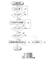
上述した第1実施形態のSOx濃度検出フローの一例について説明する。このフローが図10に示されている。
<SOx Concentration Detection Flow of First Embodiment>
An example of the SOx concentration detection flow of the first embodiment described above will be described. This flow is shown in FIG.
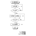
図10のフローが開始されたときには、印加電圧が0.4Vに維持されている。そして、ステップ10において、印加電圧Vsが0.4Vから0.8Vに向かって上昇される。次いで、ステップ11において、印加電圧Vsが0.8Vに達した(Vs=0.8V)か否かが判別される。ここで、Vs=0.8Vであると判別されたときには、フローはステップ12に進む。一方、Vs=0.8Vではないと判別されたときには、フローはステップ10に戻る。したがって、ステップ11においてVs=0.8Vであると判別されるまで、印加電圧Vsの上昇が継続される。
When the flow of FIG. 10 is started, the applied voltage is maintained at 0.4V. In
ステップ12では、印加電圧Vsが0.8Vから0.4Vに向かって低下されるとともに、出力電流Isが検出される。次いで、ステップ13において、印加電圧Vsが0.4Vに達した(Vs=0.4V)か否かが判別される。ここで、Vs=0.4Vであると判別されたときには、フローはステップ14に進む。一方、Vs=0.4Vではないと判別されたときには、フローはステップ12に戻る。したがって、ステップ13においてVs=0.4Vであると判別されるまで、印加電圧Vsの低下と出力電流Isの検出とが継続される。
In
ステップ14では、ステップ12で検出された出力電流Isのうち、ピーク値に基づいてSOx濃度Csoxが算出され、その後、フローは終了する。
In
<センサ素子温度>
なお、上述した実施形態のSOx濃度検出において、印加電圧が低下されたときにSOx濃度に対応する電流がセンサから出力される理由は、センサセルにおいてSOxに関連する反応が生じていることであると推察される。一方、この反応は、センサセルの温度の影響を大きく受ける。したがって、排気中のSOx濃度が極めて低いことを考慮すれば、センサセルの温度が一定に維持されていることが好ましい。そこで、上述した実施形態において、SOx濃度検出の実行時には、センサセルの温度が一定に維持されるように、ヒータが制御されるようにしてもよい。これによれば、SOx濃度がより精度高く検出される。
<Sensor element temperature>
In the SOx concentration detection of the above-described embodiment, the reason why the current corresponding to the SOx concentration is output from the sensor when the applied voltage is reduced is that a reaction related to SOx occurs in the sensor cell. Inferred. On the other hand, this reaction is greatly influenced by the temperature of the sensor cell. Therefore, considering that the SOx concentration in the exhaust gas is extremely low, it is preferable that the temperature of the sensor cell is kept constant. Therefore, in the above-described embodiment, the heater may be controlled so that the temperature of the sensor cell is kept constant when performing the SOx concentration detection. According to this, the SOx concentration is detected with higher accuracy.
<センサ搭載位置>
また、排気中の成分を浄化する触媒が排気管に設けられている場合、排気中のSOxが触媒に捕捉される可能性がある。この場合、限界電流式センサが触媒下流の排気管に取り付けられていると、SOx濃度が精度良く検出されない可能性がある。そこで、上述した実施形態において、触媒が排気管に設けられている場合、限界電流式センサが触媒上流の排気管に取り付けられていることが好ましい。
<Sensor mounting position>
Further, when a catalyst for purifying components in the exhaust is provided in the exhaust pipe, SOx in the exhaust may be trapped by the catalyst. In this case, if the limit current sensor is attached to the exhaust pipe downstream of the catalyst, the SOx concentration may not be detected with high accuracy. Therefore, in the above-described embodiment, when the catalyst is provided in the exhaust pipe, it is preferable that the limiting current type sensor is attached to the exhaust pipe upstream of the catalyst.
<第2実施形態>
第2実施形態について説明する。なお、以下で説明されない第2実施形態の構成および制御は、それぞれ、第1実施形態の構成および制御と同じであるか、あるいは、以下で説明する第2実施形態の構成または制御に鑑みたときに第1実施形態の構成または制御から当然に導き出される構成および制御である。
Second Embodiment
A second embodiment will be described. The configuration and control of the second embodiment not described below are the same as the configuration and control of the first embodiment, respectively, or when considering the configuration or control of the second embodiment described below. The configuration and control are naturally derived from the configuration or control of the first embodiment.
<第2実施形態のSOx濃度検出・S被毒回復>
第2実施形態では、印加電圧が定常的に0.4Vに維持されている。そして、第2実施形態のSOx濃度検出では、印加電圧が0.4Vから0.8Vまで上昇され、その後、印加電圧が0.8Vから0.4Vまで低下される。このとき、ECUは、印加電圧が0.8Vから0.4Vまで低下される間に当該ECUに入力された出力電流のピーク値の絶対値が第1の所定値以上であるか否かを判別する。ここで、ピーク値の絶対値が第1の所定値以上である場合、ECUは、S被毒回復制御(この制御の詳細は後述する)を実行する。一方、ピーク値の絶対値が第1の所定値よりも小さい場合、ECUは、ピーク値と参照電流とを用いてSOx濃度を算出(すなわち、検出)する。
<SOx concentration detection and S poison recovery of the second embodiment>
In the second embodiment, the applied voltage is constantly maintained at 0.4V. In the SOx concentration detection according to the second embodiment, the applied voltage is increased from 0.4 V to 0.8 V, and then the applied voltage is decreased from 0.8 V to 0.4 V. At this time, the ECU determines whether or not the absolute value of the peak value of the output current input to the ECU is not less than the first predetermined value while the applied voltage is decreased from 0.8 V to 0.4 V. To do. Here, when the absolute value of the peak value is equal to or greater than the first predetermined value, the ECU executes S poisoning recovery control (details of this control will be described later). On the other hand, when the absolute value of the peak value is smaller than the first predetermined value, the ECU calculates (that is, detects) the SOx concentration using the peak value and the reference current.
<第2実施形態の所定値>
なお、第2実施形態の第1の所定値は、たとえば、以下のように設定される。排気中のSOxの硫黄分が第1センサ電極に付着することがある。この付着S量(すなわち、第1センサ電極に付着している硫黄の量)が多くなると、前記ピーク値の絶対値が大きくなることが本願の発明者らの研究により判明している。そして、この付着S量が非常に多い場合、限界電流式センサの検出精度(特に、SOx濃度の検出精度)が低下する可能性がある。したがって、付着S量が多い場合、第1センサ電極に付着している硫黄を除去すること(すなわち、S被毒回復制御を実行すること)が好ましい。そこで、第2実施形態の第1の所定値は、たとえば、S被毒回復制御の実行が必要とされる場合におけるピーク値の絶対値(すなわち、印加電圧が0.8Vから0.4Vまで低下される間にECUに入力された出力電流のピーク値の絶対値)に設定される。
<Predetermined value of the second embodiment>
Note that the first predetermined value of the second embodiment is set as follows, for example. SOx sulfur content in the exhaust gas may adhere to the first sensor electrode. It has been found by the inventors' research that the absolute value of the peak value increases as the amount of deposited S (that is, the amount of sulfur attached to the first sensor electrode) increases. And when this amount of adhesion S is very large, there is a possibility that the detection accuracy (especially the detection accuracy of SOx concentration) of the limiting current type sensor is lowered. Therefore, when the amount of attached S is large, it is preferable to remove sulfur attached to the first sensor electrode (that is, to execute S poisoning recovery control). Therefore, the first predetermined value of the second embodiment is, for example, the absolute value of the peak value when execution of S poison recovery control is required (that is, the applied voltage is reduced from 0.8 V to 0.4 V). (The absolute value of the peak value of the output current input to the ECU).
<S被毒回復制御>
なお、S被毒回復制御は、公知の制御を採用可能であり、たとえば、印加電圧を比較的高い電圧(たとえば、0.8V以上の電圧であって、特に、1.0V)まで上昇させる制御を採用可能である。
<S poison recovery control>
The S poison recovery control can be a known control, for example, a control for increasing the applied voltage to a relatively high voltage (for example, a voltage of 0.8 V or more, and in particular, 1.0 V). Can be adopted.
<第2実施形態のSOx濃度検出装置の利点>
第2実施形態のSOx濃度検出装置によれば、S被毒(すなわち、第1センサ電極への硫黄の付着)によってセンサの検出精度が低下している可能性がある場合、S被毒回復制御が実行される。言い換えれば、S被毒によるセンサの検出精度の低下が生じている可能性がない場合に限り、SOx濃度の検出が実施される。このため、第2実施形態のSOx濃度検出装置によれば、SOx濃度をより精度良く検出することができる。
<Advantages of the SOx concentration detection apparatus of the second embodiment>
According to the SOx concentration detection apparatus of the second embodiment, when there is a possibility that the detection accuracy of the sensor is lowered due to S poisoning (that is, sulfur adhesion to the first sensor electrode), S poison recovery control is performed. Is executed. In other words, the SOx concentration is detected only when there is no possibility that the detection accuracy of the sensor is reduced due to S poisoning. For this reason, according to the SOx concentration detection apparatus of the second embodiment, the SOx concentration can be detected with higher accuracy.
<第2実施形態のSOx濃度検出フロー>
第2実施形態のSOx濃度検出フローの一例について説明する。このフローが図11に示されている。
<SOx Concentration Detection Flow of Second Embodiment>
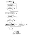
An example of the SOx concentration detection flow of the second embodiment will be described. This flow is shown in FIG.
図11のフローが開始されたときには、印加電圧が0.4Vに維持されている。そして、ステップ20において、印加電圧Vsが0.4Vから0.8Vに向かって上昇される。次いで、ステップ21において、印加電圧Vsが0.8Vに達した(Vs=0.8V)か否かが判別される。ここで、Vs=0.8Vであると判別されたときには、フローはステップ22に進む。一方、Vs=0.8Vではないと判別されたときには、フローはステップ20に戻る。したがって、ステップ21においてVs=0.8Vであると判別されるまで、印加電圧Vsの上昇が継続される。
When the flow of FIG. 11 is started, the applied voltage is maintained at 0.4V. In
ステップ22では、印加電圧Vsが0.8Vから0.4Vに向かって低下されるとともに、出力電流Isが検出される。次いで、ステップ23において、印加電圧Vsが0.4Vに達した(Vs=0.4V)か否かが判別される。ここで、Vs=0.4Vであると判別されたときには、フローはステップ24に進む。一方、Vs=0.4Vではないと判別されたときには、フローはステップ22に戻る。したがって、ステップ23においてVs=0.4Vであると判別されるまで、印加電圧Vsの低下と出力電流Isの検出とが継続される。
In
ステップ24では、ステップ22で検出された出力電流Isのうち、ピーク値の絶対値|Is|が第1の所定値Isth1よりも大きい(|Is|>Isth1)か否かが判別される。ここで、|Is|>Isth1であると判別されたときには、フローはステップ25に進み、S被毒回復制御が実行され、その後、フローは終了する。一方、|Is|>Isth1ではないと判別されたときには、フローはステップ26に進み、ステップ22で検出された出力電流Isのうち、ピーク値に基づいてSOx濃度Csoxが算出され、その後、フローは終了する。
In
<第3実施形態>
第3実施形態について説明する。なお、以下で説明されない第3実施形態の構成および制御は、それぞれ、上記実施形態の構成および制御と同じであるか、あるいは、以下で説明する第3実施形態の構成または制御に鑑みたときに上記実施形態の構成または制御から当然に導き出される構成および制御である。
<Third Embodiment>
A third embodiment will be described. The configuration and control of the third embodiment not described below are the same as the configuration and control of the above embodiment, respectively, or when considering the configuration or control of the third embodiment described below. The configuration and control are naturally derived from the configuration or control of the above embodiment.
<第3実施形態のSOx濃度検出・燃料性状異常警告>
第3実施形態では、印加電圧が定常的に0.4Vに維持されている。そして、第3実施形態のSOx濃度検出では、印加電圧が0.4Vから0.8Vまで上昇され、その後、印加電圧が0.8Vから0.4Vまで低下される。このとき、ECUは、印加電圧が0.8Vから0.4Vまで低下される間に当該ECUに入力された出力電流のピーク値の絶対値が第2の所定値以上であるか否かを判別する。ここで、ピーク値の絶対値が第2の所定値以上である場合、ECUは、燃料性状の異常を警告する。一方、ピーク値の絶対値が第2の所定値よりも小さい場合、ECUは、ピーク値と参照電流とを用いてSOx濃度を算出(すなわち、検出)する。
<SOx concentration detection / fuel property abnormality warning of the third embodiment>
In the third embodiment, the applied voltage is constantly maintained at 0.4V. In the SOx concentration detection according to the third embodiment, the applied voltage is increased from 0.4 V to 0.8 V, and then the applied voltage is decreased from 0.8 V to 0.4 V. At this time, the ECU determines whether or not the absolute value of the peak value of the output current input to the ECU is greater than or equal to the second predetermined value while the applied voltage is decreased from 0.8V to 0.4V. To do. Here, when the absolute value of the peak value is greater than or equal to the second predetermined value, the ECU warns of an abnormality in the fuel property. On the other hand, when the absolute value of the peak value is smaller than the second predetermined value, the ECU calculates (that is, detects) the SOx concentration using the peak value and the reference current.
<第3実施形態の所定値>
なお、第3実施形態の所定値は、たとえば、以下のように設定される。上述したように、排気中のSOxの硫黄分が第1センサ電極に付着することがあり、この付着S量が多くなると、前記ピーク値の絶対値が大きくなることが本願の発明者らの研究により判明している。そして、この付着S量が非常に多い場合、限界電流式センサの検出精度(特に、SOx濃度の検出精度)が低下する可能性がある。ここで、付着S量が多くなる原因の1つとして、排気中のSOx濃度が高いことが挙げられる。そして、燃料中の硫黄成分濃度が高いと、排気中のSOx濃度が高い。そして、燃料中の硫黄成分濃度が許容できない程度に高く、したがって、燃料性状が異常である可能性がある場合、その旨を警告することが好ましい。
<Predetermined value of the third embodiment>
In addition, the predetermined value of 3rd Embodiment is set as follows, for example. As described above, the sulfur content of SOx in the exhaust gas may adhere to the first sensor electrode, and when the amount of deposited S increases, the absolute value of the peak value increases. It turns out. And when this amount of adhesion S is very large, there is a possibility that the detection accuracy (especially the detection accuracy of SOx concentration) of the limiting current type sensor is lowered. Here, one of the causes that the amount of attached S increases is that the SOx concentration in the exhaust gas is high. When the sulfur component concentration in the fuel is high, the SOx concentration in the exhaust gas is high. If the sulfur component concentration in the fuel is unacceptably high, and therefore there is a possibility that the fuel property may be abnormal, it is preferable to warn that.
そこで、第3実施形態の第2の所定値は、たとえば、燃料性状が許容可能な範囲の性状ではない場合(特に、燃料中のS濃度が許容可能な濃度よりも高い場合)におけるピーク値の絶対値(すなわち、印加電圧が0.8Vから0.4Vまで低下される間にECUに入力された出力電流のピーク値の絶対値)の最小値以上の適宜選択される値に設定される。 Therefore, the second predetermined value of the third embodiment is, for example, the peak value when the fuel property is not in an allowable range (particularly when the S concentration in the fuel is higher than the allowable concentration). The absolute value (that is, the absolute value of the peak value of the output current input to the ECU while the applied voltage is reduced from 0.8 V to 0.4 V) is set to a value selected as appropriate.
なお、第3実施形態の第2の所定値は、第2実施形態の第1の所定値と同じ値であってもよいし、異なる値であってもよい。 Note that the second predetermined value of the third embodiment may be the same value as the first predetermined value of the second embodiment, or may be a different value.
<第3実施形態のSOx濃度検出装置の利点>
第3実施形態のSOx濃度検出装置によれば、燃料性状が異常である可能性がある場合、その旨が警告されるので、SOx濃度検出装置の利用者は、燃料性状が異常である可能性があることを知ることができる。
<Advantages of the SOx concentration detection apparatus of the third embodiment>
According to the SOx concentration detection device of the third embodiment, when there is a possibility that the fuel property is abnormal, a warning to that effect is given, so that the user of the SOx concentration detection device may have an abnormal fuel property. You can know that there is.
<第3実施形態のSOx濃度検出フロー>
第3実施形態のSOx濃度検出フローの一例について説明する。このフローが図12に示されている。
<SOx Concentration Detection Flow of Third Embodiment>
An example of the SOx concentration detection flow of the third embodiment will be described. This flow is shown in FIG.
図12のフローが開始されたときには、印加電圧が0.4Vに維持されている。そして、ステップ30において、印加電圧Vsが0.4Vから0.8Vに向かって上昇される。次いで、ステップ31において、印加電圧Vsが0.8Vに達した(Vs=0.8V)か否かが判別される。ここで、Vs=0.8Vであると判別されたときには、フローはステップ32に進む。一方、Vs=0.8Vではないと判別されたときには、フローはステップ30に戻る。したがって、ステップ31においてVs=0.8Vであると判別されるまで、印加電圧Vsの上昇が継続される。
When the flow of FIG. 12 is started, the applied voltage is maintained at 0.4V. In
ステップ32では、印加電圧Vsが0.8Vから0.4Vに向かって低下されるとともに、出力電流Isが検出される。次いで、ステップ33において、印加電圧Vsが0.4Vに達した(Vs=0.4V)か否かが判別される。ここで、Vs=0.4Vであると判別されたときには、フローはステップ34に進む。一方、Vs=0.4Vではないと判別されたときには、フローはステップ32に戻る。したがって、ステップ33においてVs=0.4Vであると判別されるまで、印加電圧Vsの低下と出力電流Isの検出とが継続される。
In
ステップ34では、ステップ32で検出された出力電流Isのうち、ピーク値の絶対値|Is|が第2の所定値Isth2よりも大きい(|Is|>Isth2)か否かが判別される。ここで、|Is|>Isth2であると判別されたときには、フローはステップ35に進み、燃料性状異常が警告され、その後、フローは終了する。一方、|Is|>Isth2ではないと判別されたときには、フローはステップ36に進み、ステップ32で検出された出力電流Isのうち、ピーク値に基づいてSOx濃度Csoxが算出され、その後、フローは終了する。
In
<実施形態の適用範囲>
上述した実施形態は、排気中のSOx濃度を検出する場合の実施形態である。しかしながら、上述した実施形態の考え方は、広く、印加電圧を所定の電圧から低下させたときの出力電流に相関を持つ特定成分に関するパラメータを検出する場合にも適用可能である。もちろん、この場合、検出しようとする特定成分パラメータに相関を持つ出力電流を、それ以外の特定成分に関するパラメータに相関を持つ出力電流から切り分け可能であることが条件となる。
<Scope of application>
The embodiment described above is an embodiment in the case of detecting the SOx concentration in the exhaust gas. However, the concept of the above-described embodiment is broadly applicable to detecting a parameter related to a specific component having a correlation with an output current when the applied voltage is lowered from a predetermined voltage. Of course, in this case, it is a condition that the output current correlated with the specific component parameter to be detected can be separated from the output current correlated with the parameter related to the other specific component.
別の表現をすれば、上述した実施形態の考え方は、印加電圧が一定の電圧に維持されているときの出力電流に相関を持たない(または、相関が極めて小さい)か、あるいは、印加電圧が上昇されたときの出力電流に相関を持たない(または、相関が極めて小さい)が、印加電圧が所定電圧から低下されたときの出力電流に相関を持つ特定成分に関するパラメータを検出する場合にも適用可能である。 In other words, the concept of the embodiment described above has no correlation (or a very small correlation) with the output current when the applied voltage is maintained at a constant voltage, or the applied voltage is Also applicable when detecting parameters related to specific components that have no correlation to the output current when it is raised (or very little correlation) but have a correlation to the output current when the applied voltage is reduced from the specified voltage Is possible.
上述した実施形態は、印加電圧の低下時の出力電流の最小値を用いてSOx濃度を検出する実施形態である。しかしながら、上述した実施形態の考え方は、広く、印加電圧の低下時の出力電流の最大値を用いて特定成分に関するパラメータを検出する場合にも適用可能である。 In the embodiment described above, the SOx concentration is detected using the minimum value of the output current when the applied voltage is reduced. However, the concept of the above-described embodiment is broadly applicable to a case where a parameter related to a specific component is detected using the maximum value of the output current when the applied voltage is reduced.
また、上述した実施形態のSOx濃度検出では、印加電圧の低下前に印加電圧の上昇が行われる。しかしながら、印加電圧の低下さえ行われれば、その前に印加電圧の上昇が行われなくても、上述した実施形態の利益が少なからず得られる。 In the SOx concentration detection of the above-described embodiment, the applied voltage is increased before the applied voltage is decreased. However, as long as the applied voltage is lowered, the benefits of the above-described embodiments can be obtained notwithstanding that the applied voltage is not raised before that.
<実施形態の総括>
上述した実施形態の内燃機関のSOx濃度検出装置は、広く表現すれば、限界電流式センサへの印加電圧を所定電圧(たとえば、0.8V以上の電圧であり、特に、0.8V)から低下させたときの前記センサの出力電流を用いて被検ガス中の特定成分に関するパラメータ(たとえば、排気中のSOx濃度)を検出する検出部(たとえば、ECU)を有する内燃機関の特定成分パラメータ検出装置であると言える。
<Summary of Embodiment>
The SOx concentration detection device for an internal combustion engine of the above-described embodiment can be broadly expressed by reducing the voltage applied to the limit current type sensor from a predetermined voltage (for example, a voltage of 0.8 V or more, particularly 0.8 V). A specific component parameter detection device for an internal combustion engine having a detection unit (for example, ECU) that detects a parameter (for example, SOx concentration in exhaust gas) using the output current of the sensor when detected It can be said that.
より限定的に表現すれば、前記検出部は、前記パラメータ検出用の出力電流として、前記センサへの印加電圧を前記所定電圧から低下させたときの前記センサの出力電流のピーク値を用いるものであると言える。 More specifically, the detection unit uses a peak value of the output current of the sensor when the applied voltage to the sensor is reduced from the predetermined voltage as the output current for parameter detection. It can be said that there is.
同様に、限定的に表現すれば、前記検出部は、前記パラメータ検出用の出力電流として、前記所定電圧の印加前に当該所定電圧よりも低い電圧(たとえば、0.6V以下の電圧であり、特に、0.4V)を印加し、その後、印加電圧を前記所定電圧まで上昇させ、その後、印加電圧を低下させたときの前記センサの出力電流を用いるものであると言える。なお、この場合、印加電圧の低下は、印加電圧の上昇に続いて連続的に行われる。 Similarly, if expressed in a limited manner, the detection unit is a voltage lower than the predetermined voltage (for example, a voltage of 0.6 V or less before the application of the predetermined voltage) as the output current for parameter detection, In particular, it can be said that the output current of the sensor is used when 0.4 V) is applied, and then the applied voltage is raised to the predetermined voltage and then the applied voltage is lowered. In this case, the decrease in the applied voltage is continuously performed following the increase in the applied voltage.
また、上述した実施形態の内燃機関のSOx濃度検出装置は、広く表現すれば、前記センサへの印加電圧を前記所定電圧(たとえば、0.8V以上の電圧であり、特に、0.8V)から低下させたときの前記センサの出力電流の絶対値が第1の所定値以上である場合、S被毒回復制御を実行する制御部(たとえば、ECU)をさらに有するものであると言える。 Moreover, the SOx concentration detection device for an internal combustion engine of the above-described embodiment can be broadly expressed by changing the applied voltage to the sensor from the predetermined voltage (for example, a voltage of 0.8 V or more, particularly 0.8 V). When the absolute value of the output current of the sensor at the time of reduction is equal to or greater than the first predetermined value, it can be said that the control unit (for example, ECU) that performs S poison recovery control is further included.
また、上述した実施形態の内燃機関のSOx濃度検出装置は、広く表現すれば、前記センサへの印加電圧を前記所定電圧(たとえば、0.8V以上の電圧であり、特に、0.8V)から低下させたときの前記センサへの出力電流の絶対値が第2の所定値以上である場合、燃料性状の異常を警告する制御部をさらに有するものであると言える。 Moreover, the SOx concentration detection device for an internal combustion engine of the above-described embodiment can be broadly expressed by changing the applied voltage to the sensor from the predetermined voltage (for example, a voltage of 0.8 V or more, particularly 0.8 V). When the absolute value of the output current to the sensor when it is lowered is equal to or greater than the second predetermined value, it can be said that the apparatus further includes a control unit that warns of abnormal fuel properties.
また、上述した実施形態のSOx濃度検出装置は、広く表現すれば、前記センサへの印加電圧を所定電圧(たとえば、0.8V以上の電圧であり、特に、0.8V)から低下させる電圧低下ステップと、該電圧低下ステップ中の前記センサの出力電流を取得する出力電流取得ステップと、該出力電流取得ステップにおいて取得された出力電流を用いて被検ガス中の特定成分に関するパラメータ(たとえば、排気中のSOx濃度)を検出する特定成分パラメータ検出ステップと、を具備する方法を実行するものであると言える。 In addition, the SOx concentration detection device of the above-described embodiment can be broadly expressed as a voltage drop that reduces the voltage applied to the sensor from a predetermined voltage (for example, a voltage of 0.8 V or more, particularly 0.8 V). An output current acquisition step for acquiring an output current of the sensor during the voltage drop step, and a parameter (for example, exhaust gas) using the output current acquired in the output current acquisition step It can be said that a specific component parameter detecting step for detecting (SOx concentration in the medium) is executed.
より限定的に表現すれば、上記方法は、前記出力電流取得ステップにおいて、前記センサの出力電流のピーク値を取得するものであると言える。 Expressed more specifically, it can be said that the above method acquires the peak value of the output current of the sensor in the output current acquisition step.
同様に、限定的に表現すれば、上記方法は、前記所定電圧の印加前に当該所定電圧よりも低い電圧(たとえば、0.6V以下の電圧であり、特に、0.4V)を印加しておき、印加電圧を前記所定電圧まで上昇させる電圧上昇ステップであって、前記電圧低下ステップの前に実行される電圧上昇ステップをさらに具備するものであると言える。なお、この場合、電圧低下ステップは、電圧上昇ステップに続いて連続的に実行される。 Similarly, if expressed in a limited manner, the above method applies a voltage lower than the predetermined voltage (for example, a voltage of 0.6 V or less, particularly 0.4 V) before the application of the predetermined voltage. In addition, it can be said that the method further includes a voltage increase step for increasing the applied voltage to the predetermined voltage, and a voltage increase step that is executed before the voltage decrease step. In this case, the voltage lowering step is continuously executed following the voltage increasing step.
また、上述した実施形態の限界電流式センサは、広く表現すれば、印加電圧を所定電圧(たとえば、0.8V以上の電圧であり、特に、0.8V)から低下させたときの当該センサの出力電流を用いて被検ガス中の特定成分に関するパラメータ(たとえば、排気中のSOx濃度)を検出するために用いられる限界電流式センサであると言える。 Moreover, the limiting current type sensor of the above-described embodiment can be broadly expressed as the sensor when the applied voltage is reduced from a predetermined voltage (for example, a voltage of 0.8 V or more, particularly 0.8 V). It can be said that this is a limiting current type sensor used for detecting a parameter (for example, SOx concentration in the exhaust gas) related to a specific component in the test gas using the output current.
より限定的に表現すれば、上述した実施形態のセンサは、印加電圧を前記所定電圧から低下させたときの当該センサの出力電流のピーク値を前記パラメータ検出用の出力電流として用いて前記パラメータを検出するために用いられるセンサであると言える。 More specifically, the sensor of the embodiment described above uses the peak value of the output current of the sensor when the applied voltage is lowered from the predetermined voltage as the output current for parameter detection, and the parameter is set. It can be said that the sensor is used for detection.
同様に、限定的に表現すれば、上述した実施形態のセンサは、前記所定電圧の印加前に当該所定電圧よりも低い電圧(たとえば、0.6V以下の電圧であり、特に、0.4V)を印加し、その後、印加電圧を前記所定電圧まで上昇させ、その後、印加電圧を低下させたときの当該センサの出力電流を前記パラメータ検出用の出力電流として用いて前記パラメータを検出するために用いられるセンサであると言える。なお、この場合、印加電圧の低下は、印加電圧の上昇に続いて連続的に行われる。 Similarly, if expressed in a limited manner, the sensor of the above-described embodiment has a voltage lower than the predetermined voltage (for example, a voltage of 0.6 V or less, particularly 0.4 V) before the application of the predetermined voltage. Is used to detect the parameter using the output current of the sensor when the applied voltage is increased to the predetermined voltage and then the output current of the sensor when the applied voltage is decreased. It can be said that it is a sensor. In this case, the decrease in the applied voltage is continuously performed following the increase in the applied voltage.
10…限界電流式センサ、11A、11B…固体電解質層、13…拡散律速層、15…ポンプセル、15A、15B…ポンプ電極、16…センサセル、16A、16B…センサ電極、30…限界電流式センサ、31…固体電解質層、33…拡散律速層、35…センサセル、35A、35B…センサ電極、90…ECU
DESCRIPTION OF
本発明は、内燃機関のSOx濃度検出装置に関する。 The present invention relates to an SOx concentration detection device for an internal combustion engine.
ガス混合物中の含酸素ガスの相対的量の測定用センサが特許文献1に記載されている。このセンサは2つのポンプセルを有する。これらポンプセルは直列的に配置されている。このセンサでは、上流側のポンプセルに低電圧を印加することによって、ガス混合物中の一部の含酸素ガス(特に、O2)を排除し、下流側のポンプセンサに高電圧を印加することによって、ガス混合物中の残りの含酸素ガス(特に、H2OとCO2)の相対的量が測定される。 A sensor for measuring the relative amount of oxygen-containing gas in a gas mixture is described in US Pat. This sensor has two pump cells. These pump cells are arranged in series. In this sensor, by applying a low voltage to the upstream pump cell, part of the oxygen-containing gas (especially O 2 ) in the gas mixture is eliminated, and by applying a high voltage to the downstream pump sensor. , The relative amounts of the remaining oxygenated gases (especially H 2 O and CO 2 ) in the gas mixture are measured.
ところで、限界電流式センサが知られている。このセンサでは、内燃機関から排出される排気中のSOx濃度の検出に際し、一般的には、或る一定の電圧が印加される。しかしながら、こうした電圧の印加手法では、SOx濃度を容易には精度良く検出できない。 By the way, a limit current type sensor is known. In this sensor, when detecting the SOx concentration in the exhaust gas discharged from the internal combustion engine , a certain voltage is generally applied. However, in the application method of such voltage, the easier the SOx concentration that can not be accurately detected.
ところが、本願の発明者らの研究により、限界電流式センサへの電圧の印加手法に工夫を凝らせば、従来では精度良く検出できなかったSOx濃度を限界電流式センサによって精度良く検出できることが判明した。 However, the inventors' research has revealed that the SOx concentration that could not be detected with high accuracy can be detected with high accuracy by using the limiting current type of sensor, if the method of applying a voltage to the limiting current type sensor is elaborated. .
こうした本願の発明者らの知見に基づき、本発明の目的は、内燃機関の排気中のSOx濃度を限界電流式センサによって精度良く検出することにある。 Based on the knowledge of the inventors of the present application, an object of the present invention is to detect the SOx concentration in the exhaust gas of an internal combustion engine with a limit current sensor with high accuracy.
本願の1つの発明は、限界電流式センサを有する内燃機関のSOx濃度検出装置に関する。そして、本発明のSOx濃度検出装置は、前記センサへの印加電圧(以下単に「印加電圧」)を所定電圧から低下させたときの前記センサの出力電流(以下単に「出力電流」)を用いて前記内燃機関から排出される排気中のSOx濃度を検出する検出部を有する。 One invention of this application is related with the SOx density | concentration detection apparatus of the internal combustion engine which has a limiting current type sensor. The SOx concentration detection device of the present invention uses the output current of the sensor (hereinafter simply referred to as “output current”) when the voltage applied to the sensor (hereinafter simply referred to as “applied voltage”) is reduced from a predetermined voltage. A detector for detecting the SOx concentration in the exhaust gas discharged from the internal combustion engine ;
これによれば、SOx濃度を検出することができる。特に、印加電圧が一定の電圧に維持されているときの出力電流に占めるSOxの影響、または、印加電圧が上昇されたときの出力電流に占めるSOxの影響が、同出力電流に占める他の成分の影響に比べて小さい場合であっても、印加電圧が所定電圧から低下されたときの出力電流に占めるSOxの影響が、同出力電流に占める他の成分の影響に比べて大きい場合、SOx濃度を精度良く検出することができる。 According to this, the SOx concentration can be detected. In particular, the output current is the influence of the SOx occupying the other components occupying the same output current when the influence of the SOx occupying the output current, or the applied voltage is increased when the applied voltage is maintained at a constant voltage Even if the influence is smaller than the influence of the SOx concentration , the influence of SOx on the output current when the applied voltage is reduced from the predetermined voltage is larger than the influence of other components on the output current. Can be detected with high accuracy.
また、前記検出部は、印加電圧を前記所定電圧から低下させたときの出力電流のピーク値を、前記SOx濃度検出用の出力電流として用いると好ましい。ピーク値は、印加電圧の低下中の出力電流のうち、最も小さい出力電流(または、最も大きい出力電流)である。したがって、ピーク値は、SOx濃度に精度良く対応する出力電流であると言える。このため、SOx濃度検出用の出力電流としてピーク値を用いることによって、SOx濃度をより精度良く検出することができる。 Further, the detecting section, the peak value of the output current when lowering the applied voltage from said predetermined voltage, when used as the output current for the SOx concentration detection preferred. The peak value is the smallest output current (or the largest output current) among the output currents when the applied voltage is decreasing. Therefore, it can be said that the peak value is an output current that accurately corresponds to the SOx concentration . Thus, by using the peak value as output current for SOx concentration detection, it is possible to more accurately detect the concentration of SOx.
また、前記検出部は、前記センサへの前記所定電圧の印加前に当該所定電圧よりも低い電圧を印加しておき、印加電圧を前記所定電圧まで上昇させ、その後、印加電圧を低下させたときの出力電流を、前記SOx濃度検出用の出力電流として用いるようにしてもよい。この場合、印加電圧の低下開始前にセンサに印加させておく電圧は、前記所定電圧よりも低い。このため、印加電圧の低下開始前にセンサに印加させておく電圧が前記所定電圧である場合に比べて、SOx濃度検出に消費される電力を少なくすることができる。 Further, the detection unit applies a voltage lower than the predetermined voltage before applying the predetermined voltage to the sensor, increases the applied voltage to the predetermined voltage, and then decreases the applied voltage. May be used as the output current for detecting the SOx concentration . In this case, the voltage applied to the sensor before the start of the decrease in the applied voltage is lower than the predetermined voltage. For this reason, compared with the case where the voltage applied to the sensor before the start of the decrease in applied voltage is the predetermined voltage, the power consumed for SOx concentration detection can be reduced.
また、前記所定電圧が0.8V以上の電圧であると好ましい。これによれば、SOx濃度に精度良く対応する出力電流を得ることができ、ひいては、SOx濃度を精度良く検出することができる。 The predetermined voltage is preferably 0.8 V or more. According to this, it is possible to obtain an output current accurately corresponding to the SOx concentration, and thus, it is possible to accurately detect the concentration of SOx.
また、前記所定電圧からの印加電圧の低下終了時点の印加電圧が0.7V以下の電圧であると好ましい。これによれば、SOx濃度に精度良く対応する出力電流を得ることができ、ひいては、SOx濃度を精度良く検出することができる。 Moreover, it is preferable that the applied voltage at the time when the decrease of the applied voltage from the predetermined voltage is 0.7 V or less. According to this, it is possible to obtain an output current accurately corresponding to the SOx concentration, and thus, it is possible to accurately detect the concentration of SOx.
また、前記検出部は、100Hzの電圧変化の速度以下の速度にて印加電圧を前記所定電圧から低下させるようにしてもよい。これによれば、SOx濃度に精度良く対応する出力電流を確実に得ることができ、ひいては、SOx濃度を精度良く検出することができる。 The detection unit may reduce the applied voltage from the predetermined voltage at a speed equal to or lower than a voltage change speed of 100 Hz . According to this, it is possible to reliably obtain an output current accurately corresponding to the SOx concentration, and thus, it is possible to accurately detect the concentration of SOx.
また、前記検出部は、100Hzの電圧変化の速度以下の速度にて、前記所定電圧よりも低い電圧を前記センサに印加してから前記所定電圧まで印加電圧を上昇させた後に印加電圧を前記所定電圧から低下させるようにしてもよい。これによれば、SOx濃度に精度良く対応する出力電流を確実に得ることができ、ひいては、SOx濃度を精度良く検出することができる。 In addition, the detection unit applies a voltage lower than the predetermined voltage to the sensor at a speed equal to or lower than a voltage change rate of 100 Hz, and then increases the applied voltage to the predetermined voltage, and then applies the applied voltage to the predetermined voltage. it may be due Unishi Ru is lowered from the voltage. According to this, it is possible to reliably obtain an output current accurately corresponding to the SOx concentration, and thus, it is possible to accurately detect the concentration of SOx.
また、前記内燃機関が、たとえば、ガソリンエンジンである。ガソリンエンジンは、大部分の機関運転領域において空燃比が理論空燃比で運転される。したがって、排気中の酸素濃度が低い。このため、SOx濃度を検出しやすい。 The internal combustion engine is, for example, a gasoline engine. The gasoline engine is operated at a stoichiometric air-fuel ratio in most engine operating ranges. Thus, the low oxygen concentration in the exhaust. For this reason, it is easy to detect the SOx concentration .
また、前記SOx濃度検出装置は、前記センサへの印加電圧を前記所定電圧から低下させたときの前記センサの出力電流の絶対値が第1の所定値以上である場合、S被毒回復制御を実行する制御部をさらに有していてもよい。これによれば、S被毒によるセンサの検出精度の低下が生じている可能性がない場合に限り、SOx濃度が検出される。このため、SOx濃度をより精度良く検出することができる。 Further, the SOx concentration detection device performs S poison recovery control when the absolute value of the output current of the sensor when the applied voltage to the sensor is reduced from the predetermined voltage is equal to or greater than a first predetermined value. You may have further the control part to perform. According to this, the SOx concentration is detected only when there is no possibility that the detection accuracy of the sensor is deteriorated due to S poisoning. For this reason, the SOx concentration can be detected with higher accuracy.
また、前記SOx濃度検出装置は、前記センサへの印加電圧を前記所定電圧から低下させたときの前記センサの出力電流の絶対値が第2の所定値以上である場合、前記内燃機関の燃焼室に供給される燃料の性状の異常を警告する制御部をさらに有していてもよい。これによれば、燃料性状が異常である可能性がある場合、当該SOx濃度検出装置の利用者は、燃料性状が異常である可能性があることを知ることができる。 Further, the SOx concentration detection apparatus, when the absolute value of the sensor output current when the voltage applied to the sensor was lowered from the predetermined voltage is a second predetermined value or more, the combustion of the internal combustion engine You may further have the control part which warns of abnormality of the property of the fuel supplied to a chamber . According to this, when there is a possibility that the fuel property is abnormal, the user of the SOx concentration detection device can know that the fuel property may be abnormal.
本願の別の発明は、限界電流式センサを有する内燃機関から排出される排気中のSOx濃度を検出する方法に関する。そして、この方法は、前記センサへの印加電圧を所定電圧から低下させる電圧低下ステップと、該電圧低下ステップ中の前記センサの出力電流を取得する出力電流取得ステップと、該出力電流取得ステップにおいて取得された出力電流を用いて排気中のSOx濃度を検出するSOx濃度検出ステップと、を具備する。 Another invention of the present application relates to a method for detecting SOx concentration in exhaust gas discharged from an internal combustion engine having a limiting current type sensor. In this method, the voltage applied to the sensor is reduced from a predetermined voltage, a voltage reduction step, an output current acquisition step for acquiring the output current of the sensor during the voltage reduction step, and an output current acquisition step. a SOx concentration detection step of detecting the SOx concentration in the exhaust using the output current, comprising a.
これによれば、SOx濃度を検出することができる。特に、印加電圧が一定の電圧に維持されているときの出力電流に占めるSOxの影響、または、印加電圧が上昇されたときの出力電流に占めるSOxの影響が、同出力電流に占める他の成分の影響に比べて小さい場合であっても、印加電圧が所定電圧から低下されたときの出力電流に占めるSOxの影響が、同出力電流に占める他の成分の影響に比べて大きい場合、SOx濃度を精度良く検出することができる。 According to this, the SOx concentration can be detected. In particular, the output current is the influence of the SOx occupying the other components occupying the same output current when the influence of the SOx occupying the output current, or the applied voltage is increased when the applied voltage is maintained at a constant voltage Even if the influence is smaller than the influence of the SOx concentration , the influence of SOx on the output current when the applied voltage is reduced from the predetermined voltage is larger than the influence of other components on the output current. Can be detected with high accuracy.
なお、前記出力電流取得ステップにおいて、前記センサの出力電流のピーク値を取得すると好ましい。ピーク値は、印加電圧の低下中の出力電流のうち、最も小さい出力電流(または、最も大きい出力電流)である。したがって、ピーク値は、SOx濃度に精度良く対応する出力電流であると言える。このため、SOx濃度検出用の出力電流としてピーク値を用いることによって、SOx濃度をより精度良く検出することができる。 In the output current acquisition step, it is preferable to acquire a peak value of the output current of the sensor. The peak value is the smallest output current (or the largest output current) among the output currents when the applied voltage is decreasing. Therefore, it can be said that the peak value is an output current that accurately corresponds to the SOx concentration . Thus, by using the peak value as output current for SOx concentration detection, it is possible to more accurately detect the concentration of SOx.
また、上記方法が、前記所定電圧の印加前に当該所定電圧よりも低い電圧を印加しておき、印加電圧を前記所定電圧まで上昇させる電圧上昇ステップであって、前記電圧低下ステップの前に実行される電圧上昇ステップをさらに具備していてもよい。この場合、印加電圧の低下開始前にセンサに印加させておく電圧は、前記所定電圧よりも低い。このため、印加電圧の低下開始前にセンサに印加させておく電圧が前記所定電圧である場合に比べて、SOx濃度検出に消費される電力を少なくすることができる。 Further, the above method is a voltage increasing step in which a voltage lower than the predetermined voltage is applied before the predetermined voltage is applied, and the applied voltage is increased to the predetermined voltage, and is executed before the voltage decreasing step. The step of increasing the voltage may be further included. In this case, the voltage applied to the sensor before the start of the decrease in the applied voltage is lower than the predetermined voltage. For this reason, compared with the case where the voltage applied to the sensor before the start of the decrease in applied voltage is the predetermined voltage, the power consumed for SOx concentration detection can be reduced.
また、上記方法において、前記所定電圧が0.8V以上の電圧であると好ましい。これによれば、SOx濃度に精度良く対応する出力電流を得ることができ、ひいては、SOx濃度を精度良く検出することができる。 Moreover, in the said method, it is preferable in the said predetermined voltage being a voltage more than 0.8V. According to this, it is possible to obtain an output current accurately corresponding to the SOx concentration, and thus, it is possible to accurately detect the concentration of SOx.
また、前記電圧低下ステップにおいて前記所定電圧からの印加電圧の低下終了時点の印加電圧が0.7V以下の電圧であると好ましい。これによれば、SOx濃度に精度良く対応する出力電流を得ることができ、ひいては、SOx濃度を精度良く検出することができる。 In the voltage drop step, it is preferable that the applied voltage at the end of the drop of the applied voltage from the predetermined voltage is a voltage of 0.7 V or less. According to this, it is possible to obtain an output current accurately corresponding to the SOx concentration, and thus, it is possible to accurately detect the concentration of SOx.
また、前記電圧低下ステップにおいて100Hzの電圧変化の速度以下の速度にて印加電圧を前記所定電圧から低下させると好ましい。これによれば、SOx濃度に精度良く対応する出力電流を確実に得ることができ、ひいては、SOx濃度を精度良く検出することができる。 Also, preferably the applied voltage at a rate less rate of 100Hz voltage change in the voltage drop step Ru lowers from the predetermined voltage. According to this, it is possible to reliably obtain an output current accurately corresponding to the SOx concentration, and thus, it is possible to accurately detect the concentration of SOx.
また、前記電圧上昇ステップにおいて100Hzの電圧変化の速度以下の速度にて、印加電圧を前記所定電圧まで上昇させると好ましい。これによれば、SOx濃度に精度良く対応する出力電流を確実に得ることができ、ひいては、SOx濃度を精度良く検出することができる。 Further, at a rate below the rate of 100Hz voltage change in the voltage rising step, when the applied voltage Ru is raised to the predetermined voltage preferred. According to this, it is possible to reliably obtain an output current accurately corresponding to the SOx concentration, and thus, it is possible to accurately detect the concentration of SOx.
また、上記方法が実行される内燃機関が、たとえば、ガソリンエンジンである。ガソリンエンジンは、大部分の機関運転領域において空燃比が理論空燃比で運転される。したがって、排気中の酸素濃度が低い。このため、SOx濃度を検出しやすい。 The internal combustion engine in which the above method is executed is, for example, a gasoline engine. The gasoline engine is operated at a stoichiometric air-fuel ratio in most engine operating ranges. Thus, the low oxygen concentration in the exhaust. For this reason, it is easy to detect the SOx concentration .
本願のさらに別の発明は、限界電流式センサに関する。本発明の限界電流式センサは、当該センサへの印加電圧を所定電圧から低下させたときの当該センサの出力電流(以下単に「出力電流」)を用いて内燃機関から排出される排気中のSOx濃度を検出するために用いられる。 Still another invention of the present application relates to a limiting current type sensor. The limiting current type sensor of the present invention uses SOx in exhaust discharged from an internal combustion engine using the output current of the sensor when the applied voltage to the sensor is reduced from a predetermined voltage (hereinafter simply referred to as “output current”). Used to detect concentration .
これによれば、SOx濃度を検出するための限界電流式センサを提供することができる。特に、印加電圧が一定の電圧に維持されているときの出力電流に占めるSOxの影響、または、印加電圧が上昇されたときの出力電流に占めるSOxの影響が、同出力電流に占める他の成分の影響に比べて小さい場合であっても、印加電圧が所定電圧から低下されたときの出力電流に占めるSOxの影響が、同出力電流に占める他の成分の影響に比べて大きい場合、SOx濃度を精度良く検出するための限界電流式センサを提供することができる。 According to this, the limiting current type sensor for detecting the SOx concentration can be provided. In particular, the output current is the influence of the SOx occupying the other components occupying the same output current when the influence of the SOx occupying the output current, or the applied voltage is increased when the applied voltage is maintained at a constant voltage Even if the influence is smaller than the influence of the SOx concentration , the influence of SOx on the output current when the applied voltage is reduced from the predetermined voltage is larger than the influence of other components on the output current. It is possible to provide a limiting current type sensor for accurately detecting.
また、印加電圧を前記所定電圧から低下させたときの出力電流のピーク値を、前記SOx濃度検出用の出力電流として用いて前記SOx濃度を検出するために本発明の限界電流式センサが用いられると好ましい。ピーク値は、印加電圧の低下中の出力電流のうち、最も小さい出力電流(または、最も大きい出力電流)である。したがって、ピーク値は、SOx濃度に精度良く対応する出力電流であると言える。このため、SOx濃度検出用の出力電流としてピーク値を用いることによって、SOx濃度を精度良く検出するための限界電流式センサを提供することができる。 Also, limiting current type sensor of the present invention is used to a peak value of the output current, is used as the output current for the SOx concentration detection detects the SOx concentration when the applied voltage is lowered from the predetermined voltage And preferred. The peak value is the smallest output current (or the largest output current) among the output currents when the applied voltage is decreasing. Therefore, it can be said that the peak value is an output current that accurately corresponds to the SOx concentration . Thus, by using the peak value as output current for SOx concentration detection, it is possible to provide a limiting current type sensor for accurately detecting the concentration of SOx.
また、前記所定電圧の印加前に当該所定電圧よりも低い電圧を印加しておき、印加電圧を前記所定電圧まで上昇させ、その後、印加電圧を低下させたときの出力電流を、前記SOx濃度検出用の出力電流として用いて前記SOx濃度を検出するために本発明の限界電流式センサが用いられてもよい。この場合、印加電圧の低下開始前にセンサに印加させておく電圧は、所定電圧よりも低い。このため、印加電圧の低下開始前にセンサに印加させておく電圧が所定電圧である場合に比べて、少ない消費電力によってSOx濃度を検出するための限界電流式センサを提供することができる。 Further, before applying the predetermined voltage, a voltage lower than the predetermined voltage is applied, the applied voltage is increased to the predetermined voltage, and then the output current when the applied voltage is decreased is detected as the SOx concentration. The limiting current sensor of the present invention may be used to detect the SOx concentration by using it as an output current. In this case, the voltage applied to the sensor before the applied voltage starts to decrease is lower than the predetermined voltage. Therefore, it is possible to provide a limiting current type sensor for detecting the SOx concentration with less power consumption than in the case where the voltage applied to the sensor before the start of the decrease in applied voltage is a predetermined voltage.
また、前記所定電圧が0.8V以上の電圧に設定されて本発明の限界電流式センサが用いられると好ましい。これによれば、SOx濃度に精度良く対応する出力電流を得ることができ、ひいては、SOx濃度を精度良く検出するための限界電流式センサを提供することができる。 In addition, it is preferable that the limit current sensor of the present invention is used with the predetermined voltage set to a voltage of 0.8 V or more. According to this, it is possible to obtain an output current accurately corresponding to the SOx concentration, and thus, it is possible to provide a limiting current type sensor for accurately detecting the concentration of SOx.
また、前記所定電圧から低下させたときの電圧が0.7V以下の電圧に設定されて本発明の限界電流式センサが用いられると好ましい。これによれば、SOx濃度に精度良く対応する出力電流を得ることができ、ひいては、SOx濃度を精度良く検出するための限界電流式センサを提供することができる。 Further, it is preferable that the voltage when the voltage is lowered from the predetermined voltage is set to a voltage of 0.7 V or less and the limiting current type sensor of the present invention is used. According to this, it is possible to obtain an output current accurately corresponding to the SOx concentration, and thus, it is possible to provide a limiting current type sensor for accurately detecting the concentration of SOx.
また、印加電圧を前記所定電圧から低下させるときの電圧変化の速度が100Hzの電圧変化の速度以下に設定されて本発明の限界電流式センサが用いられると好ましい。これによれば、SOx濃度に精度良く対応する出力電流を確実に得ることができ、ひいては、SOx濃度を精度良く検出するための限界電流式センサを提供することができる。 Also, limiting current type sensor of the present invention the rate of voltage change is set to a speed hereinafter the 100Hz voltage change when decreasing the applied voltage from said predetermined voltage is preferably used. According to this, it is possible to reliably obtain an output current accurately corresponding to the SOx concentration, and thus, it is possible to provide a limiting current type sensor for accurately detecting the concentration of SOx.
また、前記所定電圧よりも低い電圧を印加してから前記所定電圧まで印加電圧を上昇させた後に印加電圧を前記所定電圧から低下させるときの電圧変化の速度が100Hzの電圧変化以下に設定されて本発明の限界電流式センサが用いられると好ましい。これによれば、SOx濃度に精度良く対応する出力電流を確実に得ることができ、ひいては、SOx濃度を精度良く検出するための限界電流式センサを提供することができる。 Further, the rate of voltage change is set to a voltage change than under 100Hz when lowering the applied voltage after said from the voltage lower than the predetermined voltage to increase the voltage applied to the predetermined voltage from said predetermined voltage The limit current sensor of the present invention is preferably used. According to this, it is possible to reliably obtain an output current accurately corresponding to the SOx concentration, and thus, it is possible to provide a limiting current type sensor for accurately detecting the concentration of SOx.
また、本発明の限界電流式センサは、前記内燃機関がガソリンエンジンである場合において、前記SOx濃度を検出するために用いられてもよい。ガソリンエンジンは、大部分の機関運転領域において空燃比が理論空燃比で運転される。したがって、排気中の酸素濃度が低い。このため、SOx濃度を検出しやすい限界電流式センサを提供することができる。 Further, the limiting current type sensor of the present invention may be used for detecting the SOx concentration when the internal combustion engine is a gasoline engine. The gasoline engine is operated at a stoichiometric air-fuel ratio in most engine operating ranges. Thus, the low oxygen concentration in the exhaust. Therefore, it is possible to provide a limiting current type sensor that can easily detect the SOx concentration .
図面を参照して本発明のSOx濃度検出用の限界電流式センサの実施形態、および、該限界電流式センサを有する内燃機関から排出される排気中の硫黄酸化物(以下「SOx」)の濃度を検出するSOx濃度検出装置の実施形態について説明する。 An embodiment of a limiting current type sensor for detecting SOx concentration according to the present invention with reference to the drawings, and a concentration of sulfur oxide (hereinafter referred to as “SOx”) in exhaust discharged from an internal combustion engine having the limiting current type sensor An embodiment of a SOx concentration detection device for detecting the above will be described .
<2セルタイプ限界電流式センサの構成>
図1に本発明の第1実施形態の限界電流式センサの1つが示されている。図1の限界電流式センサは、2セルタイプの限界電流式センサである。図1において、10は限界電流式センサ、11Aは第1固体電解質層、11Bは第2固体電解質層、12Aは第1アルミナ層、12Bは第2アルミナ層、12Cは第3アルミナ層、12Dは第4アルミナ層、12Eは第5アルミナ層、12Fは第6アルミナ層、13は拡散律速層、14はヒータ、15はポンプセル、15Aは第1ポンプ電極、15Bは第2ポンプ電極、15Cはポンプセル電圧源、16はセンサセル、16Aは第1センサ電極、16Bは第2センサ電極、16Cはセンサセル電圧源、17Aは第1大気導入路、17Bは第2大気導入路、18は内部空間をそれぞれ示している。
<Configuration of 2-cell type limiting current sensor>
FIG. 1 shows one of the limiting current type sensors according to the first embodiment of the present invention. The limiting current type sensor of FIG. 1 is a two-cell type limiting current type sensor. In FIG. 1, 10 is a limiting current sensor, 11A is a first solid electrolyte layer, 11B is a second solid electrolyte layer, 12A is a first alumina layer, 12B is a second alumina layer, 12C is a third alumina layer, and 12D is 4th alumina layer, 12E is 5th alumina layer, 12F is 6th alumina layer, 13 is diffusion control layer, 14 is heater, 15 is pump cell, 15A is 1st pump electrode, 15B is 2nd pump electrode, 15C is pump cell Voltage source, 16 is a sensor cell, 16A is a first sensor electrode, 16B is a second sensor electrode, 16C is a sensor cell voltage source, 17A is a first atmosphere introduction path, 17B is a second atmosphere introduction path, and 18 is an internal space. ing.
固体電解質層11A、11Bは、ジルコニア等からなる層であり、酸素イオン伝導性を有する。アルミナ層12A〜12Fは、アルミナからなる層である。拡散律速層13は、多孔質の層であり、排気を通すことができる。センサ10では、各層は、図1において下方から、第6アルミナ層12F、第5アルミナ層12E、第4アルミナ層12D、第2固体電解質層11B、拡散律速層13および第3アルミナ層12C、第1固体電解質層11A、第2アルミナ層12B、第1アルミナ層12Aの順で積層されている。ヒータ14は、第5アルミナ層12Eと第6アルミナ層12Fとの間に配置されている。
The
第1大気導入路17Aは、第1アルミナ層12Aと第2アルミナ層12Bと第1固体電解質層11Aとによって形成された空間であり、その一部は大気に開放されている。第2大気導入路17Bは、第2固体電解質層11Bと第4アルミナ層12Dと第5アルミナ層12Eとによって形成された空間であり、その一部は大気に開放されている。内部空間18は、第1固体電解質層11Aと第2固体電解質層11Bと拡散律速層13と第3アルミナ層12Cとによって形成された空間であり、その一部は拡散律速層13を介してセンサ外部に連通している。
The first
<ポンプセルの構成>
第1ポンプ電極15Aおよび第2ポンプ電極15Bは、白金もしくはロジウム等の白金族元素またはその合金からなる電極である。第1ポンプ電極15Aは、第2固体電解質層11Bの一方の側の壁面(すなわち、内部空間18を形成する第2固体電解質層11Bの壁面)に配置され、第2ポンプ電極15Bは、第2固体電解質層11Bの他方の側の壁面(すなわち、第2大気導入路17Bを形成する第2固体電解質層11Bの壁面)に配置されている。これら電極15A、15Bと第2固体電解質層11Bとは、ポンプセル15を構成している。センサ10は、ポンプセル15(具体的には、第1ポンプ電極15Aと第2ポンプ電極15Bとの間)にポンプセル電圧源15Cから電圧を印加可能に構成されている。なお、第1ポンプ電極15Aは陰極側の電極であり、第2ポンプ電極15Bは陽極側の電極である。
<Configuration of pump cell>
The
<ポンプセルの機能>
ポンプセル15に電圧が印加されると、内部空間18内の酸素が第1ポンプ電極15Aに接触したときに、この酸素が第1ポンプ電極15A上で酸素イオンとなり、この酸素イオンが第2固体電解質層11Bの内部を第2ポンプ電極15Bに向かって移動する。このとき、第1ポンプ電極15Aと第2ポンプ電極15Bとの間には、第2固体電解質層11Bの内部を移動した酸素イオン量に比例した電流が流れる。そして、酸素イオンが第2ポンプ電極15Bに達すると、酸素イオンは第2ポンプ電極15Bにおいて酸素となって第2大気導入路17Bに放出される。つまり、ポンプセル15は、排気中の酸素を排気からポンピングによって大気に放出し、排気中の酸素濃度を低下させることができる。このポンプセル15のポンピング能力は、ポンプセル電圧源15Cから当該ポンプセル15に印加される電圧が高いほど高い。
<Pump cell function>
When a voltage is applied to the
<センサセルの構成>
第1センサ電極16Aおよび第2センサ電極16Bは、白金もしくはロジウム等の白金族元素またはその合金からなる電極である。第1センサ電極16Aは、第1固体電解質層11Aの一方の側の壁面(すなわち、内部空間18を形成する第1固体電解質層11Aの壁面)に配置され、第2センサ電極16Bは、第1固体電解質層11Aの他方の側の壁面(すなわち、第1大気導入路17Aを形成する第1固体電解質層11Aの壁面)に配置されている。これら電極16A、16Bと第1固体電解質層11Aとは、センサセル16を構成している。センサ10は、センサセル16(具体的には、第1センサ電極16Aと第2センサ電極16Bとの間)にセンサセル電圧源16Cから電圧を印加可能に構成されている。なお、第1センサ電極16Aは陰極側の電極であり、第2センサ電極16Bは陽極側の電極である。
<Configuration of sensor cell>
The
<センサセルの機能>
センサセル16に電圧が印加されると、内部空間18内のSOxが第1センサ電極16Aに接触したときに、このSOxが第1センサ電極16A上で分解され、SOxの酸素が酸素イオンとなり、この酸素イオンが第1固体電解質層11Aの内部を第2センサ電極16Bに向かって移動する。このとき、第1センサ電極16Aと第2センサ電極16Bとの間には、第1固体電解質層11Aの内部を移動した酸素イオン量に比例した電流が流れる。そして、酸素イオンが第2センサ電極16Bに達すると、酸素イオンは第2センサ電極16Bにおいて酸素となって第1大気導入路17Aに放出される。
<Function of sensor cell>
When a voltage is applied to the
<2セルタイプ限界電流式センサの出力特性>
ところで、本願の発明者らの研究により、2セルタイプの限界電流式センサへの印加電圧(具体的には、センサセル電圧源16Cからセンサセル16への印加電圧)を所定電圧から低下させることによって、排気中のSOx濃度に対応する電流をこの限界電流式センサから得られることが新たに判明した。次に、このことについて説明する。なお、以下の説明において、出力電流とはセンサセル16から出力される電流である。
<Output characteristics of 2-cell type limiting current sensor>
By the way, according to the research of the inventors of the present application, by reducing the applied voltage to the two-cell type limit current type sensor (specifically, the applied voltage from the sensor
図2に、印加電圧を0.1Vから1.0Vまで徐々に上昇させ、その後、1.0Vから0.1Vまで徐々に低下させた場合の出力電流の変化が示されている。図2の横軸は印加電圧であり、図2の縦軸は出力電流である。なお、このように印加電圧を変化させている間、ポンプセル15には、内部空間18内の排気中の酸素濃度を零(または、略零)にする電圧が印加されている。
FIG. 2 shows changes in the output current when the applied voltage is gradually increased from 0.1 V to 1.0 V and then gradually decreased from 1.0 V to 0.1 V. The horizontal axis in FIG. 2 is the applied voltage, and the vertical axis in FIG. 2 is the output current. While the applied voltage is changed in this way, a voltage that makes the oxygen concentration in the exhaust gas in the
図2において、実線LU0は、排気中にSOxが含まれていない(すなわち、排気中のSOx濃度が零である)場合において印加電圧を0.1Vから1.0Vまで上昇させたときの出力電流の変化を示し、実線LD0は、同じく排気中にSOxが含まれていない場合において印加電圧を1.0Vから0.1Vまで低下させたときの出力電流の変化を示している。図2において、一点鎖線LU1は、排気中にSOxが含まれている場合において印加電圧を0.1Vから1.0Vまで上昇させたときの出力電流の変化を示し、一点鎖線LD1は、同じく排気中にSOxが含まれている場合において印加電圧を1.0Vから0.1Vまで低下させたときの出力電流の変化を示している。 In FIG. 2, a solid line LU0 indicates an output current when the applied voltage is increased from 0.1 V to 1.0 V when SOx is not included in the exhaust (that is, when the SOx concentration in the exhaust is zero). The solid line LD0 indicates the change in the output current when the applied voltage is decreased from 1.0 V to 0.1 V when SOx is not included in the exhaust gas. In FIG. 2, an alternate long and short dash line LU1 indicates a change in output current when the applied voltage is increased from 0.1 V to 1.0 V when SOx is included in the exhaust, and an alternate long and short dash line LD1 The graph shows changes in the output current when the applied voltage is decreased from 1.0 V to 0.1 V when SOx is included therein.
排気中にSOxが含まれていない場合、印加電圧が0.1Vから約0.2Vまで上昇されると、図2の実線LU0で示されているように、出力電流が約4μAまで急激に上昇する。そして、印加電圧が約0.2Vから約0.85Vまで上昇する間は、出力電流が約4μAで略一定である。そして、印加電圧が約0.85Vを上回ると、出力電流が上昇し始める。そして、印加電圧が約0.85Vから1.0Vまで上昇される間、出力電流は徐々に上昇し、印加電圧が1.0Vに達したときに、出力電流が約7μAに達する。 When SOx is not included in the exhaust, when the applied voltage is increased from 0.1 V to about 0.2 V, the output current increases rapidly to about 4 μA, as shown by the solid line LU0 in FIG. To do. Then, while the applied voltage rises from about 0.2 V to about 0.85 V, the output current is approximately constant at about 4 μA. When the applied voltage exceeds about 0.85 V, the output current starts to increase. The output current gradually increases while the applied voltage is raised from about 0.85 V to 1.0 V. When the applied voltage reaches 1.0 V, the output current reaches about 7 μA.
そして、その後、印加電圧が1.0Vから0.4Vに向けて徐々に低下されると、図2の実線LD0で示されているように、出力電流が約7μAから徐々に低下し、印加電圧が約0.85Vを下回ってから0.4Vに達するまでの間は、出力電流が約3.5μAで略一定である。 After that, when the applied voltage is gradually decreased from 1.0 V to 0.4 V, the output current gradually decreases from about 7 μA as shown by the solid line LD0 in FIG. The output current is substantially constant at about 3.5 μA until the voltage reaches about 0.4 V after the voltage drops below about 0.85 V.
一方、排気中にSOxが含まれている場合、印加電圧が0.1Vから約0.2Vまで上昇されると、図2の一点鎖線LU1で示されているように、出力電流が約4μAまで急激に上昇する。そして、印加電圧が約0.2Vから約0.6Vまで上昇する間は、出力電流が約4μAで略一定である。そして、印加電圧が約0.6Vを上回ると、出力電流が上昇し始める。そして、印加電圧が約0.6Vから1.0Vまで上昇される間、出力電流は徐々に上昇し、印加電圧が1.0Vに達したときに約7μAに達する。 On the other hand, when SOx is contained in the exhaust gas, when the applied voltage is increased from 0.1 V to about 0.2 V, the output current is about 4 μA as shown by the one-dot chain line LU1 in FIG. Rises rapidly. While the applied voltage rises from about 0.2 V to about 0.6 V, the output current is about 4 μA and is substantially constant. When the applied voltage exceeds about 0.6 V, the output current starts to increase. The output current gradually increases while the applied voltage is raised from about 0.6 V to 1.0 V, and reaches about 7 μA when the applied voltage reaches 1.0 V.
そして、その後、印加電圧が1.0Vから0.4Vに向けて徐々に低下されると、図2の一点鎖線LD1で示されているように、出力電流が約7μAから徐々に低下し、印加電圧が約0.8Vを下回ってから約0.7Vに達するまでの間に、出力電流が急激に低下して当該出力電流の流れる方向が逆転し、約−5μAに達する。そして、印加電圧がさらに約0.7Vから0.4Vまで低下される間に、出力電流が急激に上昇して当該出力電流の流れる方向が元の方向に戻り、印加電圧が0.4Vに達すると、出力電流が約3.5μAとなる。 Then, when the applied voltage is gradually decreased from 1.0 V to 0.4 V, the output current gradually decreases from about 7 μA as shown by the one-dot chain line LD1 in FIG. Between the time when the voltage drops below about 0.8V and the time when the voltage reaches about 0.7V, the output current rapidly decreases and the direction in which the output current flows is reversed to reach about −5 μA. Then, while the applied voltage is further reduced from about 0.7V to 0.4V, the output current rapidly rises, the direction in which the output current flows returns to the original direction, and the applied voltage reaches 0.4V. Then, the output current becomes about 3.5 μA.
したがって、排気中にSOxが含まれている場合、印加電圧が0.4Vから0.8Vに上昇され、その後、印加電圧が0.8Vから0.4Vに低下されると、印加電圧が低下される間に出力電流が急激に低下した後に急激に上昇する。つまり、印加電圧が0.8Vから0.4Vまで低下されると、出力電流は最小値(すなわち、ピーク値)のある変化を示す。ここで、印加電圧が約0.7Vに達したときに、出力電流がピーク値となる。 Therefore, when SOx is included in the exhaust gas, the applied voltage is increased from 0.4 V to 0.8 V, and then the applied voltage is decreased when the applied voltage is decreased from 0.8 V to 0.4 V. During this period, the output current suddenly decreases and then increases rapidly. That is, when the applied voltage is decreased from 0.8 V to 0.4 V, the output current shows a change with a minimum value (that is, a peak value). Here, when the applied voltage reaches about 0.7 V, the output current has a peak value.
なお、排気中にSOxが含まれている場合において印加電圧が約0.6Vを上回ってから1.0Vに達するまでの出力電流は、排気中にSOxが含まれていない場合において印加電圧が約0.6Vを上回ってから1.0Vに達するまでの出力電流よりも大きい。 When SOx is included in the exhaust gas, the output current from when the applied voltage exceeds approximately 0.6 V to 1.0 V is approximately equal to the applied voltage when SOx is not included in the exhaust gas. It is larger than the output current from reaching 0.6V after exceeding 0.6V.
<第1実施形態の2セルタイプの限界電流式センサの利点>
そして、本願の発明者らの研究により、2セルタイプの限界電流式センサにおいて、上述したように印加電圧を0.8Vから0.4Vまで低下させたときの出力電流のピーク値とSOx濃度との間には、図3に示されている関係があることが判明した。つまり、参照電流(すなわち、印加電圧が0.8Vに達した時点の出力電流)と前記ピーク値との差が大きいほど、排気中のSOx濃度が高いことが判明した。したがって、第1実施形態の2セルタイプの限界電流式センサによれば、前記ピーク値を用いてSOx濃度を算出(すなわち、検出)することができる。
<Advantages of the 2-cell type limiting current sensor of the first embodiment>
According to the research of the inventors of the present application, the peak value of the output current and the SOx concentration when the applied voltage is reduced from 0.8 V to 0.4 V as described above in the two-cell type limiting current sensor, It was found that there is a relationship shown in FIG. That is, it has been found that the SOx concentration in the exhaust gas is higher as the difference between the reference current (that is, the output current when the applied voltage reaches 0.8 V) and the peak value is larger. Therefore, according to the two-cell type limiting current sensor of the first embodiment, the SOx concentration can be calculated (that is, detected) using the peak value.
<1セルタイプ限界電流式センサの構成>
図4に本発明の第1実施形態の限界電流式センサのさらに1つが示されている。図4の限界電流式センサは、1セルタイプの限界電流式センサである。図4において、30は限界電流式センサ、31は固体電解質層、32Aは第1アルミナ層、32Bは第2アルミナ層、32Cは第3アルミナ層、32Dは第4アルミナ層、32Eは第5アルミナ層、33は拡散律速層、34はヒータ、35はセンサセル、35Aは第1センサ電極、35Bは第2センサ電極、35Cはセンサセル電圧源、36は大気導入路、37は内部空間をそれぞれ示している。
<Configuration of 1-cell type limiting current sensor>
FIG. 4 shows another one of the limiting current type sensors according to the first embodiment of the present invention. The limiting current type sensor of FIG. 4 is a one-cell type limiting current type sensor. In FIG. 4, 30 is a limiting current type sensor, 31 is a solid electrolyte layer, 32A is a first alumina layer, 32B is a second alumina layer, 32C is a third alumina layer, 32D is a fourth alumina layer, and 32E is a fifth alumina. Layer, 33 is a diffusion-controlled layer, 34 is a heater, 35 is a sensor cell, 35A is a first sensor electrode, 35B is a second sensor electrode, 35C is a sensor cell voltage source, 36 is an air introduction path, and 37 is an internal space. Yes.
固体電解質層31は、ジルコニア等からなる層であり、酸素イオン伝導性を有する。アルミナ層32A〜32Eは、アルミナからなる層である。拡散律速層33は、多孔質の層であり、排気を通すことができる。センサ30では、各層は、図4において下方から、第5アルミナ層32E、第4アルミナ層32D、第3アルミナ層32C、固体電解質層31、拡散律速層33および第2アルミナ層32B、第1アルミナ層32Aの順で積層されている。ヒータ34は、第4アルミナ層32Dと第5アルミナ層32Eとの間に配置されている。
The
大気導入路36は、固体電解質層31と第3アルミナ層32Cと第4アルミナ層32Dとによって形成された空間であり、その一部は大気に開放されている。内部空間37は、第1アルミナ層32Aと固体電解質層31と拡散律速層33と第2アルミナ層32Bとによって形成された空間であり、その一部は拡散律速層33を介してセンサ外部に連通している。
The
<センサセルの構成>
第1センサ電極35Aおよび第2センサ電極35Bは、白金もしくはロジウム等の白金族元素またはその合金からなる電極である。第1センサ電極35Aは、固体電解質層31の一方の側の壁面(すなわち、内部空間37を形成する固体電解質層31の壁面)に配置され、第2センサ電極35Bは、固体電解質層31の他方の側の壁面(すなわち、大気導入路36を形成する固体電解質層31の壁面)に配置されている。これら電極35A、35Bと固体電解質層31とは、センサセル35を構成している。センサ30は、センサセル35(具体的には、第1センサ電極35Aと第2センサ電極35Bとの間)にセンサセル電圧源35Cから電圧を印加可能に構成されている。なお、第1センサ電極35Aは陰極側の電極であり、第2センサ電極35Bは陽極側の電極である。
<Configuration of sensor cell>
The
<センサセルの機能>
センサセル35に電圧が印加されると、内部空間37内のSOxが第1センサ電極35Aに接触したときに、このSOxが第1センサ電極35A上で分解され、SOxの酸素が酸素イオンとなり、この酸素イオンが固体電解質層31の内部を第2センサ電極35Bに向かって移動する。このとき、第1センサ電極35Aと第2センサ電極35Bとの間には、固体電解質層31の内部を移動した酸素イオン量に比例した電流が流れる。そして、酸素イオンが第2センサ電極35Bに達すると、酸素イオンは第2センサ電極35Bにおいて酸素となって大気導入路36に放出される。
<Function of sensor cell>
When a voltage is applied to the
<1セルタイプ限界電流式センサの出力特性>
ところで、本願の発明者らの研究により、2セルタイプの限界電流式センサと同様に、1セルタイプの限界電流式センサへの印加電圧(具体的には、センサセル電圧源35Cからセンサセル35への印加電圧)を所定電圧から低下させることによって、排気中のSOx濃度に対応する電流をこの限界電流式センサからも得られることが判明した。次に、このことについて説明する。なお、以下の説明において、出力電流とはセンサセル35から出力される電流であり、当該排気中の酸素濃度は1%で一定である。
<Output characteristics of 1-cell type limiting current sensor>
By the way, according to the research of the inventors of the present application, the voltage applied to the one-cell type limiting current type sensor (specifically, from the sensor
図5に、印加電圧を0.1Vから1.0Vまで徐々に上昇させ、その後、1.0Vから0.1Vまで徐々に低下させた場合の出力電流の変化が示されている。図5の横軸は印加電圧であり、図5の縦軸は出力電流である。 FIG. 5 shows changes in the output current when the applied voltage is gradually increased from 0.1 V to 1.0 V and then gradually decreased from 1.0 V to 0.1 V. The horizontal axis in FIG. 5 is the applied voltage, and the vertical axis in FIG. 5 is the output current.
図5において、一点鎖線LU1は、排気中にSOxが含まれている場合において印加電圧を0.1Vから1.0Vまで上昇させたときの出力電流の変化を示し、一点鎖線LD1は、同じく排気中にSOxが含まれている場合において印加電圧を1.0Vから0.1Vまで低下させたときの出力電流の変化を示している。 In FIG. 5, an alternate long and short dash line LU1 indicates a change in output current when the applied voltage is increased from 0.1 V to 1.0 V when SOx is included in the exhaust, and an alternate long and short dash line LD1 The graph shows changes in the output current when the applied voltage is decreased from 1.0 V to 0.1 V when SOx is included therein.
排気中にSOxが含まれている場合において印加電圧が0.1Vから約0.2Vまで上昇されると、図5の一点鎖線LU1で示されているように、出力電流が約100μAまで急激に上昇する。そして、印加電圧が約0.2Vから約0.6Vまで上昇する間は、出力電流が約100μAで略一定である。そして、印加電圧が約0.6Vを上回ると、出力電流が上昇し始める。そして、印加電圧が約0.6Vから1.0Vまで上昇される間、出力電流は若干ではあるが徐々に上昇し、印加電圧が1.0Vに達したときに約105μAに達する。 When SOx is included in the exhaust gas, when the applied voltage is increased from 0.1 V to about 0.2 V, the output current suddenly increases to about 100 μA as shown by the one-dot chain line LU1 in FIG. To rise. Then, while the applied voltage rises from about 0.2 V to about 0.6 V, the output current is approximately constant at about 100 μA. When the applied voltage exceeds about 0.6 V, the output current starts to increase. Then, while the applied voltage is raised from about 0.6 V to 1.0 V, the output current gradually increases slightly, and reaches about 105 μA when the applied voltage reaches 1.0 V.
そして、その後、印加電圧が1.0Vから0.4Vに向けて徐々に低下されると、図5の一点鎖線LD1で示されているように、出力電流が約105μAから徐々に低下し、印加電圧が約0.8Vを下回ってから約0.7Vに達するまでの間に、出力電流が急激に低下し、約80μAに達する。そして、印加電圧が約0.7Vから0.4Vまで低下される間に、出力電流が急激に上昇し、印加電圧が0.4Vに達すると、出力電流が約100μAとなる。 After that, when the applied voltage is gradually decreased from 1.0 V to 0.4 V, the output current is gradually decreased from about 105 μA as shown by the one-dot chain line LD1 in FIG. Between the time when the voltage drops below about 0.8 V and the time when the voltage reaches about 0.7 V, the output current rapidly decreases and reaches about 80 μA. Then, while the applied voltage is lowered from about 0.7 V to 0.4 V, the output current rises rapidly, and when the applied voltage reaches 0.4 V, the output current becomes about 100 μA.
したがって、排気中にSOxが含まれている場合、印加電圧が0.4Vから0.8Vに上昇され、その後、印加電圧が0.8Vから0.4Vに低下されると、印加電圧が低下される間に出力電流が急激に低下した後に急激に上昇する。つまり、印加電圧が0.8Vから0.4Vまで低下されると、出力電流は最小値(すなわち、ピーク値)のある変化を示す。ここで、印加電圧が約0.7Vに達したときに、出力電流がピーク値となる。 Therefore, when SOx is included in the exhaust gas, the applied voltage is increased from 0.4 V to 0.8 V, and then the applied voltage is decreased when the applied voltage is decreased from 0.8 V to 0.4 V. During this period, the output current suddenly decreases and then increases rapidly. That is, when the applied voltage is decreased from 0.8 V to 0.4 V, the output current shows a change with a minimum value (that is, a peak value). Here, when the applied voltage reaches about 0.7 V, the output current has a peak value.
<第1実施形態の1セルタイプの限界電流式センサの利点>
そして、本願の発明者らの研究により、1セルタイプの限界電流式センサにおいて、上述したように印加電圧を0.8Vから0.4Vまで低下させたときの出力電流のピーク値とSOx濃度との間にも、図3に示されている関係と同様の関係があることが判明した。つまり、参照電流(すなわち、印加電圧が0.8Vに達した時点の出力電流)と前記ピーク値との差が大きいほど、排気中のSOx濃度が高いことが判明した。したがって、第1実施形態の1セルタイプの限界電流式センサによれば、前記ピーク値を用いてSOx濃度を算出(すなわち、検出)することができる。
<Advantages of 1-cell type limiting current type sensor according to the first embodiment>
According to the research of the inventors of the present application, the peak value of the output current and the SOx concentration when the applied voltage is reduced from 0.8 V to 0.4 V as described above in the one-cell type limiting current type sensor, It was also found that there is a relationship similar to that shown in FIG. That is, it has been found that the SOx concentration in the exhaust gas is higher as the difference between the reference current (that is, the output current when the applied voltage reaches 0.8 V) and the peak value is larger. Therefore, according to the one-cell type limiting current sensor of the first embodiment, the SOx concentration can be calculated (that is, detected) using the peak value.
<第1実施形態のSOx濃度検出装置>
図6に、図1の限界電流式センサ10または図4の限界電流式センサ30を有するSOx濃度検出装置を備えた内燃機関が示されている。図6の内燃機関は、火花点火式内燃機関(いわゆるガソリンエンジン)である。しかしながら、本発明は、圧縮自着火式内燃機関(いわゆるディーゼルエンジン)にも適用可能である。また、図6の内燃機関は、大部分の機関運転領域において、空燃比が理論空燃比(ストイキ)にて運転される。
<SOx concentration detection apparatus of the first embodiment>
FIG. 6 shows an internal combustion engine equipped with a SOx concentration detection device having the limiting
<内燃機関の構成>
図6において、10または30は図1または図4の限界電流式センサ、50は内燃機関の本体、51はシリンダヘッド、52はシリンダブロック、53は燃焼室、54は燃料噴射弁、55は点火プラグ、56は燃料ポンプ、57は燃料供給管、60はピストン、61はコネクティングロッド、62はクランクシャフト、63はクランク角度センサ、70は吸気弁、71は吸気ポート、72は吸気マニホルド、73はサージタンク、74はスロットル弁、75は吸気管、76はエアフローメータ、77はエアフィルタ、80は排気弁、81は排気ポート、82は排気マニホルド、83は排気管、90は電子制御装置(ECU)、91はアクセルペダル、92はアクセルペダル踏込量センサをそれぞれ示している。
<Configuration of internal combustion engine>
6, 10 or 30 is the limiting current type sensor of FIG. 1 or FIG. 4, 50 is the body of the internal combustion engine, 51 is the cylinder head, 52 is the cylinder block, 53 is the combustion chamber, 54 is the fuel injection valve, and 55 is the ignition. Plug, 56, fuel pump, 57, fuel supply pipe, 60, piston, 61, connecting rod, 62, crankshaft, 63, crank angle sensor, 70, intake valve, 71, intake port, 72, intake manifold, 73 Surge tank, 74 throttle valve, 75 intake pipe, 76 air flow meter, 77 air filter, 80 exhaust valve, 81 exhaust port, 82 exhaust manifold, 83 exhaust pipe, 90 electronic control unit (ECU) ), 91 denotes an accelerator pedal, and 92 denotes an accelerator pedal depression amount sensor.
<ECUの構成・機能>
燃料噴射弁54、点火プラグ55、スロットル弁74、クランク角度センサ63、エアフローメータ76、アクセルペダル踏込量センサ92、および、限界電流式センサ10、30は、ECU90に電気的に接続されている。ECU90は、燃料噴射弁54、点火プラグ55、および、スロットル弁74を動作させるための信号をこれらに送信する。また、ECU90は、クランク角度センサ63、エアフローメータ76、および、アクセルペダル踏込量センサ92から信号を受信する。クランク角度センサ63からは、クランクシャフト62の回転速度に対応する信号が出力される。ECU90は、クランク角度センサ63から受信した信号に基づいて機関回転数を算出する。エアフローメータ76からは、そこを通過する空気の流量(ひいては、燃焼室53に吸入される空気の流量)に対応する信号が出力される。ECU90は、エアフローメータ76から受信した信号に基づいて吸入空気量を算出する。アクセルペダル踏込量センサ92からは、アクセルペダル91の踏込量に対応する信号が出力される。ECU90は、アクセルペダル踏込量センサ92から受信した信号に基づいて機関負荷を算出する。
<Configuration and function of ECU>
The
<限界電流式センサ>
限界電流式センサ10、30は、排気管83に取り付けられている。したがって、限界電流式センサ10、30の検出対象となるガス(すなわち、被検ガス)は、燃焼室53から排出される排気である。限界電流式センサ10、30からは、そこに到来する排気中のSOx濃度に対応する電流が出力される。ECU90は、限界電流式センサ10、30から受信した電流に基づいてSOx濃度を算出する(この算出方法の詳細は後述する)。
<Limit current sensor>
The limit
<第1実施形態のSOx濃度検出>
第1実施形態のSOx濃度検出について図7を参照しつつ説明する。第1実施形態では、印加電圧が定常的に0.4Vに維持されている(図7の時刻T0以前の期間参照)。すなわち、センサに定常的に0.4Vが印加されている。そして、第1実施形態のSOx濃度検出では、印加電圧が0.4Vから0.8Vまで上昇され(図7の時刻T0から時刻T1までの期間参照)、その後、印加電圧が0.8Vから0.4Vまで低下される(図7の時刻T1から時刻T2までの期間参照)。このとき、ECUは、印加電圧が0.8Vから0.4Vまで低下される間に当該ECUに入力された出力電流のピーク値と参照電流とを用いてSOx濃度を算出(すなわち、検出)する。このとき、参照電流とピーク値との差が大きいほど、算出されるSOx濃度は高い。
<SOx concentration detection in the first embodiment>
The SOx concentration detection of the first embodiment will be described with reference to FIG. In the first embodiment, the applied voltage is constantly maintained at 0.4 V (see the period before time T0 in FIG. 7). That is, 0.4 V is constantly applied to the sensor. In the SOx concentration detection according to the first embodiment, the applied voltage is increased from 0.4 V to 0.8 V (see the period from time T0 to time T1 in FIG. 7), and then the applied voltage is changed from 0.8 V to 0. The voltage is reduced to 4 V (see the period from time T1 to time T2 in FIG. 7). At this time, the ECU calculates (that is, detects) the SOx concentration using the peak value of the output current input to the ECU and the reference current while the applied voltage is decreased from 0.8 V to 0.4 V. . At this time, the greater the difference between the reference current and the peak value, the higher the calculated SOx concentration.
なお、ピーク値と参照電流との差(以下「電流差」)を用いてSOx濃度を算出する場合、たとえば、電流差に対応するSOx濃度が電流差毎に予め実験等によって求められ、これら求められたSOx濃度が電流差の関数のマップの形でECUに記憶され、SOx濃度の検出中に算出される電流差に対応するSOx濃度をマップから読み出すことによって、SOx濃度が算出される。 When calculating the SOx concentration using the difference between the peak value and the reference current (hereinafter referred to as “current difference”), for example, the SOx concentration corresponding to the current difference is obtained for each current difference in advance by experiments or the like. The obtained SOx concentration is stored in the ECU in the form of a current difference function map, and the SOx concentration corresponding to the current difference calculated during the detection of the SOx concentration is read out from the map to calculate the SOx concentration.
<第1実施形態のSOx濃度検出装置の利点>
第1実施形態のSOx濃度検出装置によれば、排気中のSOx濃度を検出することができる。すなわち、印加電圧が一定の電圧(たとえば、0.4V)に維持されているときの出力電流に占めるSOxの影響、または、印加電圧が上昇されたときの出力電流に占めるSOxの影響が、同出力電流に占める他の成分(たとえば、O2やNOx)の影響に比べて小さいが、印加電圧が所定電圧(たとえば、0.8V)から低下されたときの出力電流に占めるSOxの影響が、同出力電流に占める他の成分の影響に比べて大きいという知見を本願の発明者らが得ており、このため、第1実施形態のSOx濃度検出装置によれば、SOx濃度を精度良く検出することができるのである。
<Advantages of the SOx concentration detection apparatus of the first embodiment>
According to the SOx concentration detection apparatus of the first embodiment, the SOx concentration in exhaust gas can be detected. That is, the effect of SOx on the output current when the applied voltage is maintained at a constant voltage (for example, 0.4 V) or the effect of SOx on the output current when the applied voltage is increased are the same. The influence of SOx on the output current when the applied voltage is reduced from a predetermined voltage (eg, 0.8 V ) is small compared to the influence of other components (eg, O 2 and NOx) on the output current. The inventors of the present application have obtained the knowledge that this is larger than the influence of other components in the output current. For this reason, according to the SOx concentration detection device of the first embodiment, the SOx concentration can be detected with high accuracy. It can be done.
また、ピーク値は、印加電圧の低下中の出力電流のうち、SOx濃度が零である場合の出力電流から最も大きく異なる出力電流である。したがって、ピーク値は、SOx濃度に精度良く対応する出力電流であると言える。このため、SOx濃度検出用の出力電流としてピーク値を用いることによって、SOx濃度をより精度良く検出することができる。 The peak value is an output current that is most different from the output current when the SOx concentration is zero among the output currents during the decrease of the applied voltage. Therefore, it can be said that the peak value is an output current that accurately corresponds to the SOx concentration. Therefore, the SOx concentration can be detected with higher accuracy by using the peak value as the output current for detecting the SOx concentration.
また、第1実施形態では、印加電圧の低下開始前にセンサに印加させておく電圧は0.4Vである。したがって、この電圧は、印加電圧の低下開始時点の印加電圧である0.8Vよりも低い。このため、第1実施形態によれば、印加電圧の低下開始前にセンサに印加させておく電圧が0.8Vである場合に比べて、SOx濃度検出に消費される電力を少なくすることができる。 In the first embodiment, the voltage applied to the sensor before the applied voltage starts to decrease is 0.4V. Therefore, this voltage is lower than 0.8 V that is the applied voltage at the start of the decrease of the applied voltage. For this reason, according to the first embodiment, it is possible to reduce the power consumed for SOx concentration detection, compared to the case where the voltage applied to the sensor before the start of the decrease in the applied voltage is 0.8V. .
<第1実施形態の適用範囲>
なお、第1実施形態のSOx濃度検出において、印加電圧の上昇開始時点の印加電圧(すなわち、センサに定常的に印加しておく印加電圧)は、0.4Vに限定されず、印加電圧の上昇後に印加電圧を低下させたときにピーク値を持つ出力電流の変化を発生させる電圧であればよく、たとえば、0.6V以下であればよく、好ましくは、0.4Vである。
<Applicable scope of the first embodiment>
In the SOx concentration detection according to the first embodiment, the applied voltage at the start of increasing the applied voltage (that is, the applied voltage that is steadily applied to the sensor) is not limited to 0.4 V, and the applied voltage increases. Any voltage may be used as long as it causes a change in output current having a peak value when the applied voltage is lowered later. For example, the voltage may be 0.6 V or less, and preferably 0.4 V.
また、印加電圧の上昇終了時点の印加電圧は、0.8Vに限定されず、印加電圧の上昇後に印加電圧を低下させたときにピーク値を持つ出力電流の変化を発生させる電圧、または、出力安定電圧範囲(すなわち、SOx濃度が零である場合に、印加電圧に依らず出力電流が略一定である範囲であって、たとえば、0.2V〜0.8Vの範囲)の最大電圧以上の電圧であればよく、たとえば、0.8V以上であればよい。 In addition, the applied voltage at the end of the increase in the applied voltage is not limited to 0.8 V, and a voltage that generates a change in output current having a peak value when the applied voltage is lowered after the applied voltage is increased, or an output A voltage equal to or higher than the maximum voltage in the stable voltage range (that is, in the range where the output current is substantially constant regardless of the applied voltage when the SOx concentration is zero, for example, in the range of 0.2 V to 0.8 V). For example, it may be 0.8 V or more.
また、印加電圧の低下終了時点の印加電圧は、0.4Vに限定されず、ピーク値に対応する印加電圧以下であればよく、たとえば、0.7V以下であればよく、好ましくは、0.4Vである。したがって、印加電圧の上昇開始時点の印加電圧は、印加電圧の低下終了時点の印加電圧と同じであっても異なっていてもよい。 Further, the applied voltage at the end of the decrease in the applied voltage is not limited to 0.4 V, and may be equal to or lower than the applied voltage corresponding to the peak value, for example, 0.7 V or lower. 4V. Therefore, the applied voltage at the start of application voltage increase may be the same as or different from the applied voltage at the end of decrease in applied voltage.
また、第1実施形態のSOx濃度検出では、ピーク値が用いられるが、これに代えて、印加電圧が0.8Vから0.4Vまで低下される間に出力電流が急激に低下する範囲または急激に上昇する範囲の出力電流が用いられてもよい。 In the SOx concentration detection of the first embodiment, a peak value is used. Instead, a range in which the output current rapidly decreases while the applied voltage is decreased from 0.8 V to 0.4 V or abruptly. An output current in a range that rises rapidly may be used.
<参照電流>
なお、センサの内部空間に流入する排気中の酸素濃度が印加電圧の低下中に変化する場合がある。この場合、印加電圧の低下に一定時間を要することを考慮すれば、印加電圧が0.8Vであるときの出力電流よりも、印加電圧が0.4Vであるときの出力電流のほうが、ピーク値の出力時点のセンサの内部空間内の排気中の酸素濃度をより正確に反映していると言える。そこで、第1実施形態のSOx濃度検出において、印加電圧が0.8Vから0.4Vまで低下される場合、前記参照電流に代えて、印加電圧が0.4Vに達した時点の出力電流(または、その時点から所定時間経過後の出力電流)が参照電流として用いられてもよい。これによれば、排気中の酸素濃度が印加電圧の低下中に変化したとしても、SOx濃度を精度良く検出することができる。
<Reference current>
Note that the oxygen concentration in the exhaust gas flowing into the internal space of the sensor may change while the applied voltage is decreasing. In this case, considering that it takes a certain time to decrease the applied voltage, the output current when the applied voltage is 0.4 V is higher than the output current when the applied voltage is 0.8 V. It can be said that the oxygen concentration in the exhaust gas in the internal space of the sensor at the time of output is more accurately reflected. Therefore, in the SOx concentration detection according to the first embodiment, when the applied voltage is reduced from 0.8 V to 0.4 V, the output current (or when the applied voltage reaches 0.4 V, instead of the reference current) (or The output current after a predetermined time has elapsed from that point in time may be used as the reference current. According to this, even if the oxygen concentration in the exhaust gas changes while the applied voltage is decreasing, the SOx concentration can be detected with high accuracy.
また、第1実施形態において、ピーク値と参照電流とを用いてSOx濃度を算出する代わりに、ピーク値と変換係数とを用いてSOx濃度を算出するようにしてもよい。このとき、ピーク値がマイナス方向に大きいほど、算出されるSOx濃度は高い。即ち、ピーク値が負の値である場合には、ピーク値の絶対値が大きいほど、算出されるSOx濃度は高く、ピーク値が正の値である場合には、ピーク値の絶対値が小さいほど、算出されるSOx濃度は高い。なお、変換係数とは、図3の関係に従ってピーク値をSOx濃度に変換する係数である。もちろん、ピーク値がプラスの値として出現する場合には、ピーク値がプラス方向に大きいほど、算出されるSOx濃度は高いことになる。 In the first embodiment, instead of calculating the SOx concentration using the peak value and the reference current, the SOx concentration may be calculated using the peak value and the conversion coefficient. At this time, the greater the peak value in the negative direction, the higher the calculated SOx concentration. That is, when the peak value is negative, the larger the absolute value of the peak value, the higher the calculated SOx concentration, and when the peak value is positive, the absolute value of the peak value is small. The calculated SOx concentration is higher. The conversion coefficient is a coefficient for converting the peak value into the SOx concentration according to the relationship of FIG. Of course, when the peak value appears as a positive value, the calculated SOx concentration increases as the peak value increases in the positive direction.
<第1実施形態のスイープ速度>
第1実施形態のSOx濃度検出において、印加電圧の上昇速度または低下速度(スイープ速度)が速すぎると、印加電圧が低下されたとしても、ピーク値が出力されなかったり、SOx濃度に十分に対応するピーク値が出力されなかったりする可能性がある。そこで、第1実施形態のSOx濃度検出において、印加電圧が低下されたときにSOx濃度に十分に対応するピーク値が出力される印加電圧の上昇速度と低下速度とが選択されると好ましい。
<Sweep speed of the first embodiment>
In the SOx concentration detection of the first embodiment, if the applied voltage rises or falls (sweep speed) is too fast, even if the applied voltage is lowered, the peak value is not output, or the SOx concentration is sufficiently dealt with. The peak value to be output may not be output. Therefore, in the SOx concentration detection of the first embodiment, it is preferable to select an increase rate and a decrease rate of the applied voltage that outputs a peak value sufficiently corresponding to the SOx concentration when the applied voltage is decreased.
具体的には、図8(A)に示されているように、印加電圧の上昇速度が徐々に減少するように印加電圧が上昇された後、印加電圧の低下速度が徐々に増大するように印加電圧が低下されると好ましい。あるいは、図8(B)に示されているように、印加電圧の上昇速度が一定に維持されるように印加電圧が上昇された後、印加電圧の低下速度が一定に維持されるように印加電圧が低下されると好ましい。 Specifically, as shown in FIG. 8 (A), after the applied voltage is increased so that the applied voltage increases gradually, the applied voltage decreases gradually. It is preferable that the applied voltage is lowered. Alternatively, as shown in FIG. 8B, after the applied voltage is increased so that the applied voltage rise rate is maintained constant, the applied voltage is applied so that the applied voltage decrease rate is maintained constant. It is preferable if the voltage is lowered.
さらに具体的には、第1実施形態のSOx濃度検出において、印加電圧が0.4Vから0.8Vまで上昇された後、0.8Vから0.4Vまで低下されるまでの印加電圧の変化を周波数で表したとき、この周波数は、100Hz以下であることが好ましい。別の言い方をすると、印加電圧の上昇が開始されてから印加電圧の低下が終了されるまでの時間が0.01秒以上であることが好ましい。 More specifically, in the SOx concentration detection according to the first embodiment, the change in the applied voltage until the applied voltage is lowered from 0.8 V to 0.4 V after the applied voltage is raised from 0.4 V to 0.8 V. When expressed in terms of frequency, this frequency is preferably 100 Hz or less. In other words, it is preferable that the time from when the increase of the applied voltage is started to when the decrease of the applied voltage is completed is 0.01 seconds or more.
<SOx検出回路の構成1>
なお、内燃機関が図1の限界電流式センサ(2セルタイプ限界電流式センサ)を有する場合、SOx検出回路として、たとえば、図9(A)に示されている回路が採用される。図9(A)において、10は限界電流式センサ(すなわち、図1の限界電流式センサ)、14はヒータ、15はポンプセル、16はセンサセル、90はECU、91は印加電圧指令部、92はパラメータ算出部、93はヒータ制御部、94Pおよび94Sは印加電圧制御回路、95Pおよび95Sは出力電流検出回路をそれぞれ示している。
<
When the internal combustion engine has the limit current type sensor (2-cell type limit current type sensor) of FIG. 1, for example, the circuit shown in FIG. 9A is employed as the SOx detection circuit. In FIG. 9A, 10 is a limiting current type sensor (that is, the limiting current type sensor of FIG. 1), 14 is a heater, 15 is a pump cell, 16 is a sensor cell, 90 is an ECU, 91 is an applied voltage command unit, and 92 is A parameter calculation unit, 93 is a heater control unit, 94P and 94S are applied voltage control circuits, and 95P and 95S are output current detection circuits.
印加電圧指令部91、パラメータ算出部92、および、ヒータ制御部93は、ECU90の構成要素である。
The applied
印加電圧指令部91は、ポンプセル15への印加電圧に関する指令を印加電圧制御回路94Pに送信するとともに、センサセル16への印加電圧に関する指令を印加電圧制御回路94Sに送信する。
The applied
パラメータ算出部92は、ポンプセル出力電流に対応する信号を出力電流検出回路95Pから受信し、この受信した信号に基づいてポンプセル出力電流を算出する。さらに、パラメータ算出部92は、センサセル出力電流に対応する信号を出力電流検出回路95Sから受信し、この受信した信号に基づいてセンサセル出力電流を算出し、この算出した出力電流に基づいて排気中のSOx濃度を算出する。さらに、パラメータ算出部92は、出力電流検出回路95P、95Sから受信した信号に基づいてセンサ10内の回路のインピーダンスを算出し、この算出したインピーダンスに関する情報をヒータ制御部93に送信する。ヒータ制御部93は、パラメータ算出部92から受信したインピーダンスに関する情報に基づいてヒータ14を制御する制御信号をヒータ14に送信する。
The
印加電圧制御回路94Pは、印加電圧指令部91から受信した指令に基づいて(あるいは、印加電圧指令部91から受信した指令、および、出力電流検出回路95Pから提供されるポンプセル出力電流に対応する信号に基づいて)ポンプセル印加電圧を制御する。
The applied voltage control circuit 94P is based on the command received from the applied voltage command unit 91 (or the command corresponding to the command received from the applied
出力電流検出回路95Pは、ポンプセル出力電流を検出し、この検出した出力電流に対応する信号をパラメータ算出部92および印加電圧制御回路94Pに送信する。
The output
印加電圧制御回路94Sは、印加電圧指令部91から受信した指令に基づいて(あるいは、印加電圧指令部91から受信した指令、および、出力電流検出回路95Sから提供されるセンサセル出力電流に対応する信号に基づいて)センサセル印加電圧を制御する。
The applied
出力電流検出回路95Sは、センサセル出力電流を検出し、この検出した出力電流に対応する信号をパラメータ算出部92および印加電圧制御回路94Sに送信する。
The output
<SOx検出回路の構成2>
また、内燃機関が図4の限界電流式センサ(1セルタイプ限界電流式センサ)を有する場合のSOx検出回路として、たとえば、図9(B)に示されている回路が採用される。図9(B)において、30は限界電流式センサ(すなわち、図4の限界電流式センサ)、34はヒータ、35はセンサセル、90はECU、91は印加電圧指令部、92はパラメータ算出部、93はヒータ制御部、94は印加電圧制御回路、95は出力電流検出回路をそれぞれ示している。
<
Further, as the SOx detection circuit when the internal combustion engine has the limiting current type sensor (1-cell type limiting current type sensor) of FIG. 4, for example, the circuit shown in FIG. 9B is employed. In FIG. 9B, 30 is a limit current type sensor (that is, the limit current type sensor of FIG. 4), 34 is a heater, 35 is a sensor cell, 90 is an ECU, 91 is an applied voltage command unit, 92 is a parameter calculation unit,
印加電圧指令部91、パラメータ算出部92、および、ヒータ制御部93は、ECU90の構成要素である。
The applied
印加電圧指令部91は、センサセル35への印加電圧に関する指令を印加電圧制御回路94に送信する。
The applied
パラメータ算出部92は、センサセル出力電流に対応する信号を出力電流検出回路95から受信し、この受信した信号に基づいてセンサセル出力電流を算出し、この算出した出力電流に基づいて排気中のSOx濃度を算出する。さらに、パラメータ算出部92は、出力電流検出回路95から受信した信号に基づいてセンサ30内の回路のインピーダンスを算出し、この算出したインピーダンスに関する情報をヒータ制御部93に送信する。ヒータ制御部93は、パラメータ算出部92から受信したインピーダンスに関する情報に基づいてヒータ34を制御する制御信号をヒータ34に送信する。
The
印加電圧制御回路94は、印加電圧指令部91から受信した指令に基づいて(あるいは、印加電圧指令部91から受信した指令、および、出力電流検出回路95から提供されるセンサセル出力電流に対応する信号に基づいて)センサセル印加電圧を制御する。
The applied
出力電流検出回路95は、センサセル出力電流を検出し、この検出した出力電流に対応する信号をパラメータ算出部92および印加電圧制御回路94に送信する。
The output
<第1実施形態のSOx濃度検出フロー>
上述した第1実施形態のSOx濃度検出フローの一例について説明する。このフローが図10に示されている。
<SOx Concentration Detection Flow of First Embodiment>
An example of the SOx concentration detection flow of the first embodiment described above will be described. This flow is shown in FIG.
図10のフローが開始されたときには、印加電圧が0.4Vに維持されている。そして、ステップ10において、印加電圧Vsが0.4Vから0.8Vに向かって上昇される。次いで、ステップ11において、印加電圧Vsが0.8Vに達した(Vs=0.8V)か否かが判別される。ここで、Vs=0.8Vであると判別されたときには、フローはステップ12に進む。一方、Vs=0.8Vではないと判別されたときには、フローはステップ10に戻る。したがって、ステップ11においてVs=0.8Vであると判別されるまで、印加電圧Vsの上昇が継続される。
When the flow of FIG. 10 is started, the applied voltage is maintained at 0.4V. In
ステップ12では、印加電圧Vsが0.8Vから0.4Vに向かって低下されるとともに、出力電流Isが検出される。次いで、ステップ13において、印加電圧Vsが0.4Vに達した(Vs=0.4V)か否かが判別される。ここで、Vs=0.4Vであると判別されたときには、フローはステップ14に進む。一方、Vs=0.4Vではないと判別されたときには、フローはステップ12に戻る。したがって、ステップ13においてVs=0.4Vであると判別されるまで、印加電圧Vsの低下と出力電流Isの検出とが継続される。
In
ステップ14では、ステップ12で検出された出力電流Isのうち、ピーク値に基づいてSOx濃度Csoxが算出され、その後、フローは終了する。
In
<センサ素子温度>
なお、上述した実施形態のSOx濃度検出において、印加電圧が低下されたときにSOx濃度に対応する電流がセンサから出力される理由は、センサセルにおいてSOxに関連する反応が生じていることであると推察される。一方、この反応は、センサセルの温度の影響を大きく受ける。したがって、排気中のSOx濃度が極めて低いことを考慮すれば、センサセルの温度が一定に維持されていることが好ましい。そこで、上述した実施形態において、SOx濃度検出の実行時には、センサセルの温度が一定に維持されるように、ヒータが制御されるようにしてもよい。これによれば、SOx濃度がより精度高く検出される。
<Sensor element temperature>
In the SOx concentration detection of the above-described embodiment, the reason why the current corresponding to the SOx concentration is output from the sensor when the applied voltage is reduced is that a reaction related to SOx occurs in the sensor cell. Inferred. On the other hand, this reaction is greatly influenced by the temperature of the sensor cell. Therefore, considering that the SOx concentration in the exhaust gas is extremely low, it is preferable that the temperature of the sensor cell is kept constant. Therefore, in the above-described embodiment, the heater may be controlled so that the temperature of the sensor cell is kept constant when performing the SOx concentration detection. According to this, the SOx concentration is detected with higher accuracy.
<センサ搭載位置>
また、排気中の成分を浄化する触媒が排気管に設けられている場合、排気中のSOxが触媒に捕捉される可能性がある。この場合、限界電流式センサが触媒下流の排気管に取り付けられていると、SOx濃度が精度良く検出されない可能性がある。そこで、上述した実施形態において、触媒が排気管に設けられている場合、限界電流式センサが触媒上流の排気管に取り付けられていることが好ましい。
<Sensor mounting position>
Further, when a catalyst for purifying components in the exhaust is provided in the exhaust pipe, SOx in the exhaust may be trapped by the catalyst. In this case, if the limit current sensor is attached to the exhaust pipe downstream of the catalyst, the SOx concentration may not be detected with high accuracy. Therefore, in the above-described embodiment, when the catalyst is provided in the exhaust pipe, it is preferable that the limiting current type sensor is attached to the exhaust pipe upstream of the catalyst.
<第2実施形態>
第2実施形態について説明する。なお、以下で説明されない第2実施形態の構成および制御は、それぞれ、第1実施形態の構成および制御と同じであるか、あるいは、以下で説明する第2実施形態の構成または制御に鑑みたときに第1実施形態の構成または制御から当然に導き出される構成および制御である。
Second Embodiment
A second embodiment will be described. The configuration and control of the second embodiment not described below are the same as the configuration and control of the first embodiment, respectively, or when considering the configuration or control of the second embodiment described below. The configuration and control are naturally derived from the configuration or control of the first embodiment.
<第2実施形態のSOx濃度検出・S被毒回復>
第2実施形態では、印加電圧が定常的に0.4Vに維持されている。そして、第2実施形態のSOx濃度検出では、印加電圧が0.4Vから0.8Vまで上昇され、その後、印加電圧が0.8Vから0.4Vまで低下される。このとき、ECUは、印加電圧が0.8Vから0.4Vまで低下される間に当該ECUに入力された出力電流のピーク値の絶対値が第1の所定値以上であるか否かを判別する。ここで、ピーク値の絶対値が第1の所定値以上である場合、ECUは、S被毒回復制御(この制御の詳細は後述する)を実行する。一方、ピーク値の絶対値が第1の所定値よりも小さい場合、ECUは、ピーク値と参照電流とを用いてSOx濃度を算出(すなわち、検出)する。
<SOx concentration detection and S poison recovery of the second embodiment>
In the second embodiment, the applied voltage is constantly maintained at 0.4V. In the SOx concentration detection according to the second embodiment, the applied voltage is increased from 0.4 V to 0.8 V, and then the applied voltage is decreased from 0.8 V to 0.4 V. At this time, the ECU determines whether or not the absolute value of the peak value of the output current input to the ECU is not less than the first predetermined value while the applied voltage is decreased from 0.8 V to 0.4 V. To do. Here, when the absolute value of the peak value is equal to or greater than the first predetermined value, the ECU executes S poisoning recovery control (details of this control will be described later). On the other hand, when the absolute value of the peak value is smaller than the first predetermined value, the ECU calculates (that is, detects) the SOx concentration using the peak value and the reference current.
<第2実施形態の所定値>
なお、第2実施形態の第1の所定値は、たとえば、以下のように設定される。排気中のSOxの硫黄分が第1センサ電極に付着することがある。この付着S量(すなわち、第1センサ電極に付着している硫黄の量)が多くなると、前記ピーク値の絶対値が大きくなることが本願の発明者らの研究により判明している。そして、この付着S量が非常に多い場合、限界電流式センサの検出精度(特に、SOx濃度の検出精度)が低下する可能性がある。したがって、付着S量が多い場合、第1センサ電極に付着している硫黄を除去すること(すなわち、S被毒回復制御を実行すること)が好ましい。そこで、第2実施形態の第1の所定値は、たとえば、S被毒回復制御の実行が必要とされる場合におけるピーク値の絶対値(すなわち、印加電圧が0.8Vから0.4Vまで低下される間にECUに入力された出力電流のピーク値の絶対値)に設定される。
<Predetermined value of the second embodiment>
Note that the first predetermined value of the second embodiment is set as follows, for example. SOx sulfur content in the exhaust gas may adhere to the first sensor electrode. It has been found by the inventors' research that the absolute value of the peak value increases as the amount of deposited S (that is, the amount of sulfur attached to the first sensor electrode) increases. And when this amount of adhesion S is very large, there is a possibility that the detection accuracy (especially the detection accuracy of SOx concentration) of the limiting current type sensor is lowered. Therefore, when the amount of attached S is large, it is preferable to remove sulfur attached to the first sensor electrode (that is, to execute S poisoning recovery control). Therefore, the first predetermined value of the second embodiment is, for example, the absolute value of the peak value when execution of S poison recovery control is required (that is, the applied voltage is reduced from 0.8 V to 0.4 V). (The absolute value of the peak value of the output current input to the ECU).
<S被毒回復制御>
なお、S被毒回復制御は、公知の制御を採用可能であり、たとえば、印加電圧を比較的高い電圧(たとえば、0.8V以上の電圧であって、特に、1.0V)まで上昇させる制御を採用可能である。
<S poison recovery control>
The S poison recovery control can be a known control, for example, a control for increasing the applied voltage to a relatively high voltage (for example, a voltage of 0.8 V or more, and in particular, 1.0 V). Can be adopted.
<第2実施形態のSOx濃度検出装置の利点>
第2実施形態のSOx濃度検出装置によれば、S被毒(すなわち、第1センサ電極への硫黄の付着)によってセンサの検出精度が低下している可能性がある場合、S被毒回復制御が実行される。言い換えれば、S被毒によるセンサの検出精度の低下が生じている可能性がない場合に限り、SOx濃度の検出が実施される。このため、第2実施形態のSOx濃度検出装置によれば、SOx濃度をより精度良く検出することができる。
<Advantages of the SOx concentration detection apparatus of the second embodiment>
According to the SOx concentration detection apparatus of the second embodiment, when there is a possibility that the detection accuracy of the sensor is lowered due to S poisoning (that is, sulfur adhesion to the first sensor electrode), S poison recovery control is performed. Is executed. In other words, the SOx concentration is detected only when there is no possibility that the detection accuracy of the sensor is reduced due to S poisoning. For this reason, according to the SOx concentration detection apparatus of the second embodiment, the SOx concentration can be detected with higher accuracy.
<第2実施形態のSOx濃度検出フロー>
第2実施形態のSOx濃度検出フローの一例について説明する。このフローが図11に示されている。
<SOx Concentration Detection Flow of Second Embodiment>
An example of the SOx concentration detection flow of the second embodiment will be described. This flow is shown in FIG.
図11のフローが開始されたときには、印加電圧が0.4Vに維持されている。そして、ステップ20において、印加電圧Vsが0.4Vから0.8Vに向かって上昇される。次いで、ステップ21において、印加電圧Vsが0.8Vに達した(Vs=0.8V)か否かが判別される。ここで、Vs=0.8Vであると判別されたときには、フローはステップ22に進む。一方、Vs=0.8Vではないと判別されたときには、フローはステップ20に戻る。したがって、ステップ21においてVs=0.8Vであると判別されるまで、印加電圧Vsの上昇が継続される。
When the flow of FIG. 11 is started, the applied voltage is maintained at 0.4V. In
ステップ22では、印加電圧Vsが0.8Vから0.4Vに向かって低下されるとともに、出力電流Isが検出される。次いで、ステップ23において、印加電圧Vsが0.4Vに達した(Vs=0.4V)か否かが判別される。ここで、Vs=0.4Vであると判別されたときには、フローはステップ24に進む。一方、Vs=0.4Vではないと判別されたときには、フローはステップ22に戻る。したがって、ステップ23においてVs=0.4Vであると判別されるまで、印加電圧Vsの低下と出力電流Isの検出とが継続される。
In
ステップ24では、ステップ22で検出された出力電流Isのうち、ピーク値の絶対値|Is|が第1の所定値Isth1よりも大きい(|Is|>Isth1)か否かが判別される。ここで、|Is|>Isth1であると判別されたときには、フローはステップ25に進み、S被毒回復制御が実行され、その後、フローは終了する。一方、|Is|>Isth1ではないと判別されたときには、フローはステップ26に進み、ステップ22で検出された出力電流Isのうち、ピーク値に基づいてSOx濃度Csoxが算出され、その後、フローは終了する。
In
<第3実施形態>
第3実施形態について説明する。なお、以下で説明されない第3実施形態の構成および制御は、それぞれ、上記実施形態の構成および制御と同じであるか、あるいは、以下で説明する第3実施形態の構成または制御に鑑みたときに上記実施形態の構成または制御から当然に導き出される構成および制御である。
<Third Embodiment>
A third embodiment will be described. The configuration and control of the third embodiment not described below are the same as the configuration and control of the above embodiment, respectively, or when considering the configuration or control of the third embodiment described below. The configuration and control are naturally derived from the configuration or control of the above embodiment.
<第3実施形態のSOx濃度検出・燃料性状異常警告>
第3実施形態では、印加電圧が定常的に0.4Vに維持されている。そして、第3実施形態のSOx濃度検出では、印加電圧が0.4Vから0.8Vまで上昇され、その後、印加電圧が0.8Vから0.4Vまで低下される。このとき、ECUは、印加電圧が0.8Vから0.4Vまで低下される間に当該ECUに入力された出力電流のピーク値の絶対値が第2の所定値以上であるか否かを判別する。ここで、ピーク値の絶対値が第2の所定値以上である場合、ECUは、燃料性状の異常を警告する。一方、ピーク値の絶対値が第2の所定値よりも小さい場合、ECUは、ピーク値と参照電流とを用いてSOx濃度を算出(すなわち、検出)する。
<SOx concentration detection / fuel property abnormality warning of the third embodiment>
In the third embodiment, the applied voltage is constantly maintained at 0.4V. In the SOx concentration detection according to the third embodiment, the applied voltage is increased from 0.4 V to 0.8 V, and then the applied voltage is decreased from 0.8 V to 0.4 V. At this time, the ECU determines whether or not the absolute value of the peak value of the output current input to the ECU is greater than or equal to the second predetermined value while the applied voltage is decreased from 0.8V to 0.4V. To do. Here, when the absolute value of the peak value is greater than or equal to the second predetermined value, the ECU warns of an abnormality in the fuel property. On the other hand, when the absolute value of the peak value is smaller than the second predetermined value, the ECU calculates (that is, detects) the SOx concentration using the peak value and the reference current.
<第3実施形態の所定値>
なお、第3実施形態の所定値は、たとえば、以下のように設定される。上述したように、排気中のSOxの硫黄分が第1センサ電極に付着することがあり、この付着S量が多くなると、前記ピーク値の絶対値が大きくなることが本願の発明者らの研究により判明している。そして、この付着S量が非常に多い場合、限界電流式センサの検出精度(特に、SOx濃度の検出精度)が低下する可能性がある。ここで、付着S量が多くなる原因の1つとして、排気中のSOx濃度が高いことが挙げられる。そして、燃料中の硫黄成分濃度が高いと、排気中のSOx濃度が高い。そして、燃料中の硫黄成分濃度が許容できない程度に高く、したがって、燃料性状が異常である可能性がある場合、その旨を警告することが好ましい。
<Predetermined value of the third embodiment>
In addition, the predetermined value of 3rd Embodiment is set as follows, for example. As described above, the sulfur content of SOx in the exhaust gas may adhere to the first sensor electrode, and when the amount of deposited S increases, the absolute value of the peak value increases. It turns out. And when this amount of adhesion S is very large, there is a possibility that the detection accuracy (especially the detection accuracy of SOx concentration) of the limiting current type sensor is lowered. Here, one of the causes that the amount of attached S increases is that the SOx concentration in the exhaust gas is high. When the sulfur component concentration in the fuel is high, the SOx concentration in the exhaust gas is high. If the sulfur component concentration in the fuel is unacceptably high, and therefore there is a possibility that the fuel property may be abnormal, it is preferable to warn that.
そこで、第3実施形態の第2の所定値は、たとえば、燃料性状が許容可能な範囲の性状ではない場合(特に、燃料中のS濃度が許容可能な濃度よりも高い場合)におけるピーク値の絶対値(すなわち、印加電圧が0.8Vから0.4Vまで低下される間にECUに入力された出力電流のピーク値の絶対値)の最小値以上の適宜選択される値に設定される。 Therefore, the second predetermined value of the third embodiment is, for example, the peak value when the fuel property is not in an allowable range (particularly when the S concentration in the fuel is higher than the allowable concentration). The absolute value (that is, the absolute value of the peak value of the output current input to the ECU while the applied voltage is reduced from 0.8 V to 0.4 V) is set to a value selected as appropriate.
なお、第3実施形態の第2の所定値は、第2実施形態の第1の所定値と同じ値であってもよいし、異なる値であってもよい。 Note that the second predetermined value of the third embodiment may be the same value as the first predetermined value of the second embodiment, or may be a different value.
<第3実施形態のSOx濃度検出装置の利点>
第3実施形態のSOx濃度検出装置によれば、燃料性状が異常である可能性がある場合、その旨が警告されるので、SOx濃度検出装置の利用者は、燃料性状が異常である可能性があることを知ることができる。
<Advantages of the SOx concentration detection apparatus of the third embodiment>
According to the SOx concentration detection device of the third embodiment, when there is a possibility that the fuel property is abnormal, a warning to that effect is given, so that the user of the SOx concentration detection device may have an abnormal fuel property. You can know that there is.
<第3実施形態のSOx濃度検出フロー>
第3実施形態のSOx濃度検出フローの一例について説明する。このフローが図12に示されている。
<SOx Concentration Detection Flow of Third Embodiment>
An example of the SOx concentration detection flow of the third embodiment will be described. This flow is shown in FIG.
図12のフローが開始されたときには、印加電圧が0.4Vに維持されている。そして、ステップ30において、印加電圧Vsが0.4Vから0.8Vに向かって上昇される。次いで、ステップ31において、印加電圧Vsが0.8Vに達した(Vs=0.8V)か否かが判別される。ここで、Vs=0.8Vであると判別されたときには、フローはステップ32に進む。一方、Vs=0.8Vではないと判別されたときには、フローはステップ30に戻る。したがって、ステップ31においてVs=0.8Vであると判別されるまで、印加電圧Vsの上昇が継続される。
When the flow of FIG. 12 is started, the applied voltage is maintained at 0.4V. In
ステップ32では、印加電圧Vsが0.8Vから0.4Vに向かって低下されるとともに、出力電流Isが検出される。次いで、ステップ33において、印加電圧Vsが0.4Vに達した(Vs=0.4V)か否かが判別される。ここで、Vs=0.4Vであると判別されたときには、フローはステップ34に進む。一方、Vs=0.4Vではないと判別されたときには、フローはステップ32に戻る。したがって、ステップ33においてVs=0.4Vであると判別されるまで、印加電圧Vsの低下と出力電流Isの検出とが継続される。
In
ステップ34では、ステップ32で検出された出力電流Isのうち、ピーク値の絶対値|Is|が第2の所定値Isth2よりも大きい(|Is|>Isth2)か否かが判別される。ここで、|Is|>Isth2であると判別されたときには、フローはステップ35に進み、燃料性状異常が警告され、その後、フローは終了する。一方、|Is|>Isth2ではないと判別されたときには、フローはステップ36に進み、ステップ32で検出された出力電流Isのうち、ピーク値に基づいてSOx濃度Csoxが算出され、その後、フローは終了する。
In
上述した実施形態のSOx濃度検出では、印加電圧の低下前に印加電圧の上昇が行われる。しかしながら、印加電圧の低下さえ行われれば、その前に印加電圧の上昇が行われなくても、上述した実施形態の利益が少なからず得られる。 The SOx concentration detection embodiment described above mentioned increase of the applied voltage is performed before lowering the applied voltage. However, as long as the applied voltage is lowered, the benefits of the above-described embodiments can be obtained notwithstanding that the applied voltage is not raised before that.
<実施形態の総括>
上述した実施形態の内燃機関のSOx濃度検出装置は、広く表現すれば、限界電流式センサへの印加電圧を所定電圧(たとえば、0.8V以上の電圧であり、特に、0.8V)から低下させたときの前記センサの出力電流を用いて排気中のSOx濃度を検出する検出部(たとえば、ECU)を有する内燃機関のSOx濃度検出装置であると言える。
<Summary of Embodiment>
The SOx concentration detection device for an internal combustion engine of the above-described embodiment can be broadly expressed by reducing the voltage applied to the limit current type sensor from a predetermined voltage (for example, a voltage of 0.8 V or more, particularly 0.8 V). It can be said that this is a SOx concentration detection device for an internal combustion engine having a detection unit (for example, ECU) that detects the SOx concentration in the exhaust gas using the output current of the sensor at the time.
より限定的に表現すれば、前記検出部は、前記SOx濃度検出用の出力電流として、前記センサへの印加電圧を前記所定電圧から低下させたときの前記センサの出力電流のピーク値を用いるものであると言える。 More specifically, the detection unit uses a peak value of the output current of the sensor when the applied voltage to the sensor is decreased from the predetermined voltage as the output current for detecting the SOx concentration. It can be said that.
同様に、限定的に表現すれば、前記検出部は、前記SOx濃度検出用の出力電流として、前記所定電圧の印加前に当該所定電圧よりも低い電圧(たとえば、0.6V以下の電圧であり、特に、0.4V)を印加し、その後、印加電圧を前記所定電圧まで上昇させ、その後、印加電圧を低下させたときの前記センサの出力電流を用いるものであると言える。なお、この場合、印加電圧の低下は、印加電圧の上昇に続いて連続的に行われる。 Similarly, if expressed in a limited manner, the detection unit is a voltage lower than the predetermined voltage (for example, a voltage of 0.6 V or less before the application of the predetermined voltage) as the output current for detecting the SOx concentration . In particular, it can be said that the output current of the sensor when the applied voltage is raised to the predetermined voltage and then the applied voltage is lowered is applied. In this case, the decrease in the applied voltage is continuously performed following the increase in the applied voltage.
また、上述した実施形態の内燃機関のSOx濃度検出装置は、広く表現すれば、前記センサへの印加電圧を前記所定電圧(たとえば、0.8V以上の電圧であり、特に、0.8V)から低下させたときの前記センサの出力電流の絶対値が第1の所定値以上である場合、S被毒回復制御を実行する制御部(たとえば、ECU)をさらに有するものであると言える。 Moreover, the SOx concentration detection device for an internal combustion engine of the above-described embodiment can be broadly expressed by changing the applied voltage to the sensor from the predetermined voltage (for example, a voltage of 0.8 V or more, particularly 0.8 V). When the absolute value of the output current of the sensor at the time of reduction is equal to or greater than the first predetermined value, it can be said that the control unit (for example, ECU) that performs S poison recovery control is further included.
また、上述した実施形態の内燃機関のSOx濃度検出装置は、広く表現すれば、前記センサへの印加電圧を前記所定電圧(たとえば、0.8V以上の電圧であり、特に、0.8V)から低下させたときの前記センサの出力電流の絶対値が第2の所定値以上である場合、燃料性状の異常を警告する制御部をさらに有するものであると言える。 Moreover, the SOx concentration detection device for an internal combustion engine of the above-described embodiment can be broadly expressed by changing the applied voltage to the sensor from the predetermined voltage (for example, a voltage of 0.8 V or more, particularly 0.8 V). If the absolute value of the sensor output current when reduced is the second predetermined value or more, it can be said that those further having a control unit for warning abnormality of the fuel property.
また、上述した実施形態のSOx濃度検出装置は、広く表現すれば、前記センサへの印加電圧を所定電圧(たとえば、0.8V以上の電圧であり、特に、0.8V)から低下させる電圧低下ステップと、該電圧低下ステップ中の前記センサの出力電流を取得する出力電流取得ステップと、該出力電流取得ステップにおいて取得された出力電流を用いて排気中のSOx濃度を検出するSOx濃度検出ステップと、を具備する方法を実行するものであると言える。 In addition, the SOx concentration detection device of the above-described embodiment can be broadly expressed as a voltage drop that lowers the voltage applied to the sensor from a predetermined voltage (for example, a voltage of 0.8 V or more, particularly 0.8 V). a step, the output current acquiring an output current of the sensor during the voltage drop step, the SOx concentration detection step of detecting the SOx concentration in the exhaust using the obtained output current in the output current acquisition step It can be said that the method comprising:
より限定的に表現すれば、上記方法は、前記出力電流取得ステップにおいて、前記センサの出力電流のピーク値を取得するものであると言える。 Expressed more specifically, it can be said that the above method acquires the peak value of the output current of the sensor in the output current acquisition step.
同様に、限定的に表現すれば、上記方法は、前記所定電圧の印加前に当該所定電圧よりも低い電圧(たとえば、0.6V以下の電圧であり、特に、0.4V)を印加しておき、印加電圧を前記所定電圧まで上昇させる電圧上昇ステップであって、前記電圧低下ステップの前に実行される電圧上昇ステップをさらに具備するものであると言える。なお、この場合、電圧低下ステップは、電圧上昇ステップに続いて連続的に実行される。 Similarly, if expressed in a limited manner, the above method applies a voltage lower than the predetermined voltage (for example, a voltage of 0.6 V or less, particularly 0.4 V) before the application of the predetermined voltage. In addition, it can be said that the method further includes a voltage increase step for increasing the applied voltage to the predetermined voltage, and a voltage increase step that is executed before the voltage decrease step. In this case, the voltage lowering step is continuously executed following the voltage increasing step.
また、上述した実施形態の限界電流式センサは、広く表現すれば、印加電圧を所定電圧(たとえば、0.8V以上の電圧であり、特に、0.8V)から低下させたときの当該センサの出力電流を用いて排気中のSOx濃度を検出するために用いられる限界電流式センサであると言える。 Moreover, the limiting current type sensor of the above-described embodiment can be broadly expressed as the sensor when the applied voltage is reduced from a predetermined voltage (for example, a voltage of 0.8 V or more, particularly 0.8 V). It can be said that the sensor is a limiting current type sensor used for detecting the SOx concentration in the exhaust gas using the output current.
より限定的に表現すれば、上述した実施形態のセンサは、印加電圧を前記所定電圧から低下させたときの当該センサの出力電流のピーク値を前記SOx濃度検出用の出力電流として用いて前記SOx濃度を検出するために用いられるセンサであると言える。 In more limited terms, the sensor of the above-mentioned embodiment, by using the peak value of the output current of the sensor when the applied voltage is lowered from the predetermined voltage as an output current for the SOx concentration detection SOx It can be said that the sensor is used for detecting the concentration .
同様に、限定的に表現すれば、上述した実施形態のセンサは、前記所定電圧の印加前に当該所定電圧よりも低い電圧(たとえば、0.6V以下の電圧であり、特に、0.4V)を印加し、その後、印加電圧を前記所定電圧まで上昇させ、その後、印加電圧を低下させたときの当該センサの出力電流を前記SOx濃度検出用の出力電流として用いて前記SOx濃度を検出するために用いられるセンサであると言える。なお、この場合、印加電圧の低下は、印加電圧の上昇に続いて連続的に行われる。 Similarly, if expressed in a limited manner, the sensor of the above-described embodiment has a voltage lower than the predetermined voltage (for example, a voltage of 0.6 V or less, particularly 0.4 V) before the application of the predetermined voltage. It was applied, then the applied voltage is increased to the predetermined voltage, then the output current of the sensor when lowering the applied voltage for detecting the SOx concentration is used as the output current for the SOx concentration detection It can be said that this is a sensor used in In this case, the decrease in the applied voltage is continuously performed following the increase in the applied voltage.
10…限界電流式センサ、11A、11B…固体電解質層、13…拡散律速層、15…ポンプセル、15A、15B…ポンプ電極、16…センサセル、16A、16B…センサ電極、30…限界電流式センサ、31…固体電解質層、33…拡散律速層、35…センサセル、35A、35B…センサ電極、90…ECU
DESCRIPTION OF
Claims (13)
Priority Applications (4)
| Application Number | Priority Date | Filing Date | Title |
|---|---|---|---|
| JP2013146279A JP5981398B2 (en) | 2013-07-12 | 2013-07-12 | SOx concentration detection device for internal combustion engine |
| US14/903,826 US9732659B2 (en) | 2013-07-12 | 2014-06-13 | SOx concentration detection device of internal combustion engine |
| CN201480039676.XA CN105393115B (en) | 2013-07-12 | 2014-06-13 | The SOx concentration detection devices of internal combustion engine |
| PCT/JP2014/003173 WO2015004846A1 (en) | 2013-07-12 | 2014-06-13 | SOx CONCENTRATION DETECTION DEVICE OF INTERNAL COMBUSTION ENGINE |
Applications Claiming Priority (1)
| Application Number | Priority Date | Filing Date | Title |
|---|---|---|---|
| JP2013146279A JP5981398B2 (en) | 2013-07-12 | 2013-07-12 | SOx concentration detection device for internal combustion engine |
Publications (2)
| Publication Number | Publication Date |
|---|---|
| JP2015017932A true JP2015017932A (en) | 2015-01-29 |
| JP5981398B2 JP5981398B2 (en) | 2016-08-31 |
Family
ID=52439046
Family Applications (1)
| Application Number | Title | Priority Date | Filing Date |
|---|---|---|---|
| JP2013146279A Expired - Fee Related JP5981398B2 (en) | 2013-07-12 | 2013-07-12 | SOx concentration detection device for internal combustion engine |
Country Status (1)
| Country | Link |
|---|---|
| JP (1) | JP5981398B2 (en) |
Cited By (8)
| Publication number | Priority date | Publication date | Assignee | Title |
|---|---|---|---|---|
| JP2015155849A (en) * | 2014-02-20 | 2015-08-27 | トヨタ自動車株式会社 | Control device of internal combustion engine |
| JP2015155850A (en) * | 2014-02-20 | 2015-08-27 | トヨタ自動車株式会社 | Control device of internal combustion engine |
| JP2016099317A (en) * | 2014-11-26 | 2016-05-30 | トヨタ自動車株式会社 | Control apparatus for internal combustion engine |
| US9903833B2 (en) | 2013-08-23 | 2018-02-27 | Toyota Jidosha Kabushiki Kaisha | Control device and control method for internal combustion engine |
| US9970371B2 (en) | 2013-08-23 | 2018-05-15 | Toyota Jidosha Kabushiki Kaisha | Control apparatus and control method for internal combustion engine |
| JP2018091662A (en) * | 2016-11-30 | 2018-06-14 | トヨタ自動車株式会社 | Gas detector |
| JP2018132317A (en) * | 2017-02-13 | 2018-08-23 | トヨタ自動車株式会社 | Gas detector |
| CN109959694A (en) * | 2017-12-14 | 2019-07-02 | 丰田自动车株式会社 | The SOx concentration acquisition device of internal combustion engine |
Citations (9)
| Publication number | Priority date | Publication date | Assignee | Title |
|---|---|---|---|---|
| JPS5647751A (en) * | 1979-09-27 | 1981-04-30 | Mitsui Eng & Shipbuild Co Ltd | Measuring method for concentration |
| JPS60155966A (en) * | 1983-09-01 | 1985-08-16 | グラヴルベル | Method and device for monitoring state of redox of element in glass |
| JPS62150153A (en) * | 1985-12-24 | 1987-07-04 | Fujikura Ltd | Measurement of gas concentration |
| JPH02118446A (en) * | 1987-12-11 | 1990-05-02 | Hitachi Ltd | Solution quantitative analysis apparatus, quantitative analysis and water quality control system for nuclear reactor |
| JPH03100454A (en) * | 1989-09-14 | 1991-04-25 | Fujikura Ltd | Method for recovering limiting current type oxygen sensor from deterioration |
| US5667652A (en) * | 1993-11-19 | 1997-09-16 | Gas Research Institute | Multi-functional sensor for combustion systems |
| JPH1073561A (en) * | 1996-08-30 | 1998-03-17 | Osaka Gas Co Ltd | Oxygen concentration measuring apparatus |
| US6051123A (en) * | 1995-06-15 | 2000-04-18 | Gas Research Institute | Multi-functional and NOx sensor for combustion systems |
| JP2003293744A (en) * | 2002-04-04 | 2003-10-15 | Toyota Motor Corp | Exhaust emission control device for internal combustion engine |
-
2013
- 2013-07-12 JP JP2013146279A patent/JP5981398B2/en not_active Expired - Fee Related
Patent Citations (9)
| Publication number | Priority date | Publication date | Assignee | Title |
|---|---|---|---|---|
| JPS5647751A (en) * | 1979-09-27 | 1981-04-30 | Mitsui Eng & Shipbuild Co Ltd | Measuring method for concentration |
| JPS60155966A (en) * | 1983-09-01 | 1985-08-16 | グラヴルベル | Method and device for monitoring state of redox of element in glass |
| JPS62150153A (en) * | 1985-12-24 | 1987-07-04 | Fujikura Ltd | Measurement of gas concentration |
| JPH02118446A (en) * | 1987-12-11 | 1990-05-02 | Hitachi Ltd | Solution quantitative analysis apparatus, quantitative analysis and water quality control system for nuclear reactor |
| JPH03100454A (en) * | 1989-09-14 | 1991-04-25 | Fujikura Ltd | Method for recovering limiting current type oxygen sensor from deterioration |
| US5667652A (en) * | 1993-11-19 | 1997-09-16 | Gas Research Institute | Multi-functional sensor for combustion systems |
| US6051123A (en) * | 1995-06-15 | 2000-04-18 | Gas Research Institute | Multi-functional and NOx sensor for combustion systems |
| JPH1073561A (en) * | 1996-08-30 | 1998-03-17 | Osaka Gas Co Ltd | Oxygen concentration measuring apparatus |
| JP2003293744A (en) * | 2002-04-04 | 2003-10-15 | Toyota Motor Corp | Exhaust emission control device for internal combustion engine |
Cited By (11)
| Publication number | Priority date | Publication date | Assignee | Title |
|---|---|---|---|---|
| US9903833B2 (en) | 2013-08-23 | 2018-02-27 | Toyota Jidosha Kabushiki Kaisha | Control device and control method for internal combustion engine |
| US9970371B2 (en) | 2013-08-23 | 2018-05-15 | Toyota Jidosha Kabushiki Kaisha | Control apparatus and control method for internal combustion engine |
| JP2015155849A (en) * | 2014-02-20 | 2015-08-27 | トヨタ自動車株式会社 | Control device of internal combustion engine |
| JP2015155850A (en) * | 2014-02-20 | 2015-08-27 | トヨタ自動車株式会社 | Control device of internal combustion engine |
| US9982622B2 (en) | 2014-02-20 | 2018-05-29 | Toyota Jidosha Kabushiki Kaisha | Control system and control method for internal combustion engine |
| US10551364B2 (en) | 2014-02-20 | 2020-02-04 | Toyota Jidosha Kabushiki Kaisha | Control system and control method for internal combustion engine |
| JP2016099317A (en) * | 2014-11-26 | 2016-05-30 | トヨタ自動車株式会社 | Control apparatus for internal combustion engine |
| JP2018091662A (en) * | 2016-11-30 | 2018-06-14 | トヨタ自動車株式会社 | Gas detector |
| JP2018132317A (en) * | 2017-02-13 | 2018-08-23 | トヨタ自動車株式会社 | Gas detector |
| CN109959694A (en) * | 2017-12-14 | 2019-07-02 | 丰田自动车株式会社 | The SOx concentration acquisition device of internal combustion engine |
| CN109959694B (en) * | 2017-12-14 | 2021-05-28 | 丰田自动车株式会社 | SOx concentration acquisition device for internal combustion engine |
Also Published As
| Publication number | Publication date |
|---|---|
| JP5981398B2 (en) | 2016-08-31 |
Similar Documents
| Publication | Publication Date | Title |
|---|---|---|
| JP5969433B2 (en) | SOx concentration detection device for internal combustion engine | |
| JP5981398B2 (en) | SOx concentration detection device for internal combustion engine | |
| US9732659B2 (en) | SOx concentration detection device of internal combustion engine | |
| JP6235270B2 (en) | Control device and control method for internal combustion engine | |
| JP6090203B2 (en) | Control device for internal combustion engine | |
| JP5910648B2 (en) | Control device for internal combustion engine | |
| JP5999377B2 (en) | Control device for internal combustion engine | |
| US8327620B2 (en) | NOx sensor compensation | |
| JP2015155665A (en) | Control device of internal combustion engine | |
| US9903833B2 (en) | Control device and control method for internal combustion engine | |
| US20160061771A1 (en) | Gas concentration detecting device | |
| US9891188B2 (en) | Gas concentration detecting device | |
| JP2015036538A (en) | Control device of internal combustion engine and control method | |
| US10605765B2 (en) | Gas detection device | |
| US20190136738A1 (en) | Sensor system | |
| JP5440724B1 (en) | Control device for internal combustion engine | |
| JP2019105586A (en) | Device for acquiring sox concentration in internal combustion engine | |
| CN105393115B (en) | The SOx concentration detection devices of internal combustion engine | |
| JP2019105585A (en) | Device for acquiring sox concentration in internal combustion engine | |
| JP2019078676A (en) | Sulfur oxide index acquiring device of internal combustion engine | |
| JP2019109063A (en) | SOx concentration acquisition device for internal combustion engine |
Legal Events
| Date | Code | Title | Description |
|---|---|---|---|
| A131 | Notification of reasons for refusal |
Free format text: JAPANESE INTERMEDIATE CODE: A131 Effective date: 20150728 |
|
| A521 | Request for written amendment filed |
Free format text: JAPANESE INTERMEDIATE CODE: A523 Effective date: 20150928 |
|
| A131 | Notification of reasons for refusal |
Free format text: JAPANESE INTERMEDIATE CODE: A131 Effective date: 20160308 |
|
| A521 | Request for written amendment filed |
Free format text: JAPANESE INTERMEDIATE CODE: A523 Effective date: 20160427 |
|
| TRDD | Decision of grant or rejection written | ||
| A01 | Written decision to grant a patent or to grant a registration (utility model) |
Free format text: JAPANESE INTERMEDIATE CODE: A01 Effective date: 20160705 |
|
| A61 | First payment of annual fees (during grant procedure) |
Free format text: JAPANESE INTERMEDIATE CODE: A61 Effective date: 20160728 |
|
| R150 | Certificate of patent or registration of utility model |
Ref document number: 5981398 Country of ref document: JP Free format text: JAPANESE INTERMEDIATE CODE: R150 |
|
| R250 | Receipt of annual fees |
Free format text: JAPANESE INTERMEDIATE CODE: R250 |
|
| R250 | Receipt of annual fees |
Free format text: JAPANESE INTERMEDIATE CODE: R250 |
|
| LAPS | Cancellation because of no payment of annual fees |