JP2015017444A - Hanging door device - Google Patents
Hanging door device Download PDFInfo
- Publication number
- JP2015017444A JP2015017444A JP2013145747A JP2013145747A JP2015017444A JP 2015017444 A JP2015017444 A JP 2015017444A JP 2013145747 A JP2013145747 A JP 2013145747A JP 2013145747 A JP2013145747 A JP 2013145747A JP 2015017444 A JP2015017444 A JP 2015017444A
- Authority
- JP
- Japan
- Prior art keywords
- opening
- suspension
- support bracket
- suspension vehicle
- fixed
- Prior art date
- Legal status (The legal status is an assumption and is not a legal conclusion. Google has not performed a legal analysis and makes no representation as to the accuracy of the status listed.)
- Granted
Links
Images
Landscapes
- Support Devices For Sliding Doors (AREA)
Abstract
【課題】開閉体の閉鎖速度を適宜に調整できる上、その調整作業等を、開口部側から容易に行うことができ、閉鎖動作性、製造性及びメンテナンス性等が向上した吊戸装置を提供する。
【解決手段】制動手段70は、回転可能に歯車71aを支持するとともに歯車71aの回転抵抗を調整可能にした本体部71と、歯車71aに噛み合うラック72とを備え、本体部71を、通路用開口部の上方であって吊車支持ブラケット50の一方向側に固定し、ラック72を不動部位に固定した。
【選択図】図3Provided is a hanging door device in which the closing speed of an opening / closing body can be adjusted appropriately, and the adjustment work and the like can be easily performed from the opening side, and the closing operability, manufacturability and maintainability are improved. To do.
A braking means includes a main body portion 71 that rotatably supports a gear 71a and that can adjust a rotational resistance of the gear 71a, and a rack 72 that meshes with the gear 71a. The main body portion 71 is used for a passage. The rack 72 was fixed to the stationary part above the opening and fixed to one side of the suspension vehicle support bracket 50.
[Selection] Figure 3
Description
本発明は、例えば、吊式の折戸や、吊式の引戸、バランスドア、スライディングウォール等、吊られた状態の開閉体を開閉動作するようにした吊戸装置に関するものである。 The present invention relates to a hanging door device that opens and closes a suspended opening / closing body such as a hanging folding door, a hanging sliding door, a balance door, and a sliding wall.
従来、この種の発明には、例えば特許文献1に記載のもののように、回動しながら開閉するように支持された開閉体(110)と、該開閉体(110)を閉鎖方向へ付勢するための付勢機構(142)とを具備し、開閉体(110)が所定の開閉途中位置よりも閉鎖方向側の付勢範囲以内に位置する際にはその開閉体(110)を付勢機構(142)によって閉鎖方向へ付勢し、開閉体(110)が前記付勢範囲よりも開放方向側に位置する際にはその開閉体(110)を付勢しないようにした開閉扉がある。
Conventionally, in this type of invention, for example, as disclosed in
ところで、前記従来技術では、全開時の開閉体(110)を閉鎖する際、開閉体(110)を前記付勢範囲になるまで閉鎖方向へ手動で動かす必要があり、高齢者や身障者等、使用者によっては負担になる場合がある。また、前記付勢範囲よりも若干開放方向側に位置する開閉体に、通行人や物などが接触して、不意に開閉体(110)が閉鎖動作してしまうおそれもある。
また、前記従来技術では、折戸を構成する戸尻側の扉体(112)の基軸内に、付勢機構(142)及びダンパー機構(150)等を備えているため、付勢機構(142)及びダンパー機構(150)に対し、製造時やメンテナンス時の作業がし難い場合もある。
By the way, in the said prior art, when closing the opening-closing body (110) at the time of full opening, it is necessary to move an opening-closing body (110) manually in a closing direction until it becomes the said urging | biasing range, and elderly people, a disabled person, etc. use Depending on the person, it may be a burden. Further, a passerby or an object may come into contact with the opening / closing body located slightly on the opening direction side from the biasing range, and the opening / closing body (110) may be unexpectedly closed.
Moreover, in the said prior art, since the biasing mechanism (142), the damper mechanism (150), etc. are provided in the base shaft of the door body (112) by the side of the door bottom which comprises a folding door, biasing mechanism (142) In some cases, the damper mechanism (150) may be difficult to perform during manufacturing or maintenance.
本発明は上記従来事情に鑑みてなされたものであり、その課題とする処は、閉鎖動作性、製造性及びメンテナンス性等の良好な吊戸装置を提供する。 This invention is made | formed in view of the said conventional situation, The process made into the subject provides favorable hanging door apparatuses, such as closing operation property, manufacturability, and maintainability.
上記課題を解決するための一手段は、通路用開口部幅方向へ延設されたレール部材と、該レール部材上を転動する吊車と、該吊車を回転可能に支持する吊車支持ブラケットと、該吊車支持ブラケットの下端に吊持された開閉体と、前記開閉体の閉鎖動作に抵抗を与える制動手段とを備え、付勢手段の付勢力によって前記吊車及び前記吊車支持ブラケットを前記レール部材に沿う一方向へ移動させながら前記開閉体を閉鎖動作するようにした吊戸装置において、前記制動手段は、回転可能に歯車を支持するとともに該歯車の回転抵抗を調整可能にした本体部と、前記歯車に噛み合うラックとを備え、前記本体部を、通路用開口部の上方であって前記吊車支持ブラケットの前記一方向側に固定し、前記ラックを不動部位に固定したことを特徴とする。 One means for solving the above problems is a rail member extending in the width direction of the opening for the passage, a suspension wheel that rolls on the rail member, a suspension vehicle support bracket that rotatably supports the suspension vehicle, An opening / closing body suspended from the lower end of the suspension vehicle support bracket, and a braking means for imparting resistance to a closing operation of the opening / closing body. The suspension vehicle and the suspension vehicle support bracket are attached to the rail member by an urging force of the urging device. In the hanging door device that is configured to perform the closing operation of the opening and closing body while moving in one direction along the body, the braking means supports the gear rotatably and adjusts the rotational resistance of the gear; and A rack that meshes with a gear, and the main body is fixed to the one-way side of the suspension vehicle support bracket above the passage opening, and the rack is fixed to a stationary part. .
本発明は、以上説明したように構成されているので、閉鎖動作性、製造性及びメンテナンス性等の良好な吊戸装置を提供することができる。 Since the present invention is configured as described above, it is possible to provide a favorable hanging door device such as closing operation property, manufacturability and maintenance property.
本実施の形態の吊戸装置の第一の特徴は、通路用開口部幅方向へ延設されたレール部材と、該レール部材上を転動する吊車と、該吊車を回転可能に支持する吊車支持ブラケットと、該吊車支持ブラケットの下端に吊持された開閉体と、前記開閉体の閉鎖動作に抵抗を与える制動手段とを備え、付勢手段の付勢力によって前記吊車及び前記吊車支持ブラケットを前記レール部材に沿う一方向へ移動させながら前記開閉体を閉鎖動作するようにした吊戸装置において、前記制動手段は、回転可能に歯車を支持するとともに該歯車の回転抵抗を調整可能にした本体部と、前記歯車に噛み合うラックとを備え、前記本体部を、通路用開口部の上方であって前記吊車支持ブラケットの前記一方向側に固定し、前記ラックを不動部位に固定した。
この構成によれば、開閉体の閉鎖速度を適宜に調整できる上、その調整作業等を、開口部側から容易に行うことができ、閉鎖動作性、製造性及びメンテナンス性等に優れている。
The first feature of the suspension door device of the present embodiment is that a rail member extending in the width direction of the passage opening, a suspension wheel that rolls on the rail member, and a suspension vehicle that rotatably supports the suspension vehicle. A support bracket, an opening / closing body suspended from a lower end of the suspension vehicle support bracket, and a braking unit that provides resistance to a closing operation of the opening / closing body, and the suspension vehicle and the suspension vehicle support bracket are mounted by an urging force of the urging unit. In the hanging door device configured to close the opening and closing body while moving in one direction along the rail member, the brake means supports the gear rotatably and allows the rotation resistance of the gear to be adjusted. And a rack meshing with the gear, and the main body is fixed to the one-way side of the suspension vehicle support bracket above the passage opening, and the rack is fixed to a stationary part.
According to this configuration, the closing speed of the opening / closing body can be adjusted appropriately, and the adjustment operation and the like can be easily performed from the opening side, and the closing operation performance, manufacturability, maintenance performance, and the like are excellent.
第二の特徴としては、前記ラックを、不動部位に対し通路用開口部幅方向へスライド可能に固定した。
この構成によれば、前記ラックを、通路用開口部幅方向の任意の位置で固定することができ、ひいては、前記制動手段による減速の開始位置を適宜に調整することができる。
As a second feature, the rack is fixed so as to be slidable in the width direction of the passage opening with respect to the stationary part.
According to this configuration, the rack can be fixed at an arbitrary position in the passage opening width direction, and as a result, the start position of deceleration by the braking means can be appropriately adjusted.
第三の特徴としては、前記吊車支持ブラケットの前記一方向側に連結プレートを介して取付ブラケットを固定し、該取付ブラケットに、前記制動手段の本体部を支持した。
この構成によれば、前記制動手段の本体部を前記取付ブラケットと一体状の部材として扱うことができ、ひいては、当該吊戸装置の製造性及びメンテナンス性等を向上することができる。
As a third feature, a mounting bracket is fixed to the one side of the suspension vehicle support bracket via a connecting plate, and the main body portion of the braking means is supported by the mounting bracket.
According to this structure, the main-body part of the said braking means can be handled as a member integral with the said attachment bracket, and, by extension, the manufacturability, maintenance property, etc. of the said suspension door apparatus can be improved.
第四の特徴としては、前記付勢手段は、ワイヤを巻き取り可能であってその巻取り力を調整可能なリール装置であり、このリール装置は、開閉体全閉時の前記取付ブラケットよりも前記一方向側における不動部位に支持され、前記ワイヤの先端を前記取付ブラケットに止着している。
この構成によれば、良好な閉鎖動作性を得ることができる上、付勢手段(リール装置)に対する組付性及びメンテナンス性等を向上することができる。
As a fourth feature, the urging means is a reel device capable of winding a wire and adjusting its winding force, and this reel device is more than the mounting bracket when the opening / closing body is fully closed. The wire is supported by a stationary part on the one-direction side, and the tip of the wire is fixed to the mounting bracket.
According to this configuration, it is possible to obtain a good closing operation, and it is possible to improve the assembling property and the maintenance property for the urging means (reel device).
第五の特徴としては、前記連結プレートに被掛止部を設けるとともに、前記開閉体の全開位置で前記被掛止部を係脱可能に係止する係脱部材を、前記レール部材に、通路用開口部幅方向へスライド可能に固定した。
この構成によれば、開閉体を全開位置で係脱する構成を、製造性及びメンテナンス性の良好な具体的態様とすることができる上、係脱部材を通路用開口部幅方向へ移動して全開位置を調整することもできる。
As a fifth feature, an engagement / disengagement member that engages and disengages the engagement portion at a fully open position of the opening / closing body is provided in the rail member, and a passage is provided in the connection plate. It was fixed to be slidable in the opening width direction.
According to this configuration, the configuration in which the opening / closing body is engaged / disengaged at the fully opened position can be made a specific aspect with good manufacturability and maintainability, and the engagement / disengagement member is moved in the width direction of the passage opening. The fully open position can also be adjusted.
第六の特徴としては、前記開閉体は、前記吊車支持ブラケットに吊持されて通路用開口部幅方向へ移動しながら戸先側を開口部と交差する両方向へ回動する両開き戸を構成しており、開閉体全閉時の前記吊持支持ブラケットよりも前記一方向側の不動部位には、隙間を置いた状態で前記吊持支持ブラケットを吸引する磁性吸引体が設けられ、前記取付ブラケットには、前記磁性吸引体によって吸引される被吸引体が固定されている。
ここで、「両開き戸」には、折戸やバランスドア等を含むが、回転ドアや引戸等は含まない。
前記構成によれば、両開き可能な開閉体が、全閉位置を通り過ぎて、開口部交差方向へ回動してしまうのを防ぐことができる。
As a sixth feature, the opening / closing body constitutes a double hinged door that is suspended by the suspension vehicle support bracket and moves in the direction of the width of the passage opening while rotating the door end in both directions intersecting the opening. And a magnetic attracting member that attracts the suspension support bracket with a gap provided between the suspension support bracket when the opening and closing body is fully closed and provided in the one direction side of the suspension support bracket. An object to be attracted by the magnetic attracting body is fixed to the body.
Here, the “double swing door” includes a folding door and a balance door, but does not include a revolving door or a sliding door.
According to the said structure, it can prevent that the opening / closing body which can be opened both ends passes through a fully closed position, and rotates to an opening part crossing direction.
次に、上記特徴を有する好ましい実施例を、図面に基づいて詳細に説明する。
なお、本明細書中、「通路用開口部幅方向」とは、開閉体10によって開閉される通路用開口部の横幅方向を意味する。また、前記「通路用開口部貫通方向」とは、開閉体10によって開閉される通路用開口部を貫通する方向であって、前記通路用開口部幅方向に略直交する方向を意味する。
Next, a preferred embodiment having the above features will be described in detail with reference to the drawings.
In the present specification, “passage opening width direction” means a lateral width direction of the passage opening opened and closed by the opening /
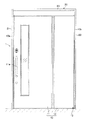
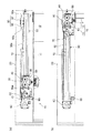
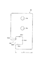
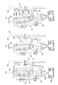
この吊戸装置1は、通路用開口部を横幅方向へ広げたり狭めたりして開閉動作する開閉体10と、該開閉体10を左右方向側および上方側から囲む枠体20と、該枠体20を構成する上枠の内部に固定されたレール部材30と、該レール部材30上を転動する吊車40と、該吊車40を回転可能に支持する吊車支持ブラケット50と、該吊車支持ブラケット50をレール部材30に沿う一方向(図1及び図2によれば左方向)へ付勢する付勢手段60と、吊車支持ブラケット50に抵抗を与える制動手段70と、開閉体10の全閉状態を保持する磁性吸引体80と、吊車支持ブラケット50をその開放方向側で係脱する係脱部材90とを備え、付勢手段60の付勢力によって吊車40及び吊車支持ブラケット50を前記一方向へ移動させながら開閉体10を閉鎖動作する(図1〜図4参照)。
特に本実施例の吊戸装置1は、建築物等の躯体壁面に設けられた開口部分に装着され、開閉体10を折り畳むようにして開放動作させて、通路用開口部を開放する折戸装置を構成している。
The hanging
In particular, the hanging
開閉体10は、複数の扉体11,12を通路用開口部幅方向(図1によれば左右方向)に連設するとともに、隣り合う扉体11,12のうちの一方を他方に対して双方向へ回動するように接続している。
そして、この開閉体10は、吊車支持ブラケット50に吊持されて通路用開口部幅方向へ移動しながら戸先側を通路用開口部と交差する両方向へ回動する両開きの折戸を構成している(図7参照)。
なお、図示例によれば、開閉体10は、二つの扉体11,12により構成しているが、3以上の扉体を前記と同様に接続するようにしてもよい。
The opening /
The opening /
In addition, according to the example of illustration, although the opening /
最戸先側の扉体11は、戸尻側の扉体12よりも幅広な略矩形板状を呈し、その上端部が、後述する吊車40及び吊車支持ブラケット50等によって吊持されることで、その吊持部分を中心にして回動しながら通路用開口部幅方向(図1における左右方向)へ移動可能である。なお、図1中の符号11aは、扉体11の戸先側における表部及び/又は裏部から通路用開口部貫通方向へ突出する取っ手部である。
そして、扉体11の戸尻側(図1によれば右側)の端部は、蝶番や歯車、リンク部材等の回動機構を介して、扉体12の戸先側(図1によれば左側)の端部に対し回動自在に接続されている。
The
And the edge part of the door bottom side (right side according to FIG. 1) of the
また、戸尻側の扉体12は、戸先側の扉体11よりも幅狭な略矩形板状に形成され、その戸尻側の端部が、枠体20及び床面等の不動部位に対し、基軸部13を介して双方向へ回動するように支持されている。
The door-
また、枠体20は、全閉時の開閉体10の戸先部10aに対向する戸先側縦枠部21と、全閉時の開閉体10の戸尻部10bに対向する戸尻側縦枠部22と、これら縦枠部21,22間をその上端側で連結する上枠部23とから略コ字枠状に構成され、中空状の上枠部23内には、開閉体10を吊持して開閉するための機構(レール部材30及び吊車40など)を収納している。
なお、図示例によれば、開閉体10の下方側は、床面や地面等としているが、両縦枠部21,22間にわたる下枠部としてもよい。
Further, the
According to the illustrated example, the lower side of the opening /
レール部材30は、吊車40を下方側から受けて通路用開口部幅方向(図1及び図2によれば左右方向)へ導くように、上枠部23に略水平に固定されている。
詳細に説明すれば、このレール部材30は、略水平状の受片部31と、上枠部23に止着される固定片部32とからなる断面略L字状に形成され、通路用開口部幅方向へ連続している。
The
More specifically, the
受片部31は、上枠部23面から突出して通路用開口部幅方向へ略水平に延設される略平板状を呈し、その通路用開口部貫通方向の一端側(図6によれば左端側)に、上方へ突出して吊車40の外周面を受けるレール状突起31aを有する。このレール状突起31aは、図示例によれば、吊車40外周面に嵌り合う断面半円状に形成され通路用開口部幅方向へ連続している。
The receiving piece 31 has a substantially flat plate shape that protrudes from the surface of the
固定片部32は、上枠部23面に固定されるとともに通路用開口部幅方向へ延設された略平板状を呈し、下端側を受片部31に接続している。この固定片部32の上端側には、被嵌合レール32aが設けられる。
The fixed
被嵌合レール32aは、レール部材30の全長にわたって連続する略凹状に形成される。より詳細に説明すれば、この被嵌合レール32aは、通路用開口部貫通方向の奥側(図6によれば右側)に、その手前側よりも上下へ幅広であって通路用開口部幅方向へ連続するガイド溝32a1を有する。このガイド溝32a1には、制動手段70のラック72又は係脱部材90に挿通された止着具(例えば、ネジ又はボルト等)に螺合したナット状部材(図示せず)が、通路用開口部幅方向へスライドするように嵌め合わされている。
この被嵌合レール32aによれば、後述する制動手段70のラック72や係脱部材90を、通路用開口部幅方向へスライドさせて、任意の位置にて、前記止着具の締め付けによって固定することが可能である(図2参照)。
The fitted
According to this fitted
また、吊車40は、略円筒状の部材であり、その全外周面にわたって、レール部材30のレール状突起31aに嵌り合う断面略半円状の凹部を有する。この吊車40は、ベアリングや軸状部材等を介して吊車支持ブラケット50に回転自在に支持され、レール状突起31a上を転動する。
Moreover, the
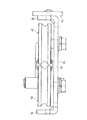
吊車支持ブラケット50は、吊車40の進退方向の両端部と同吊車40の一側面とを囲む断面略凹状(図4参照)に形成される。
詳細に説明すれば、この吊車支持ブラケット50は、吊車40を軸支する略垂直板状の基部51と、該基部51の進退方向の両端部側に吊車40側へ略直角に曲げられた補強部52,52とから断面略凹状に形成されるとともに(図4参照)、基部51の下端側に、吊車40側へ略直角に曲げられた吊持片部53(図6参照)を有する。
The suspension
More specifically, the suspension
基部51における閉鎖方向側(図3によれば左方向側)には、連結プレート56が、止着具(例えば、ネジやボルト等)によって固定される。
この連結プレート56は、平板状の部材であり、その閉鎖方向側に取付ブラケット57を、止着具(例えば、ネジやボルト等)によって固定し、上端側には、係脱部材90によって係止される被掛止部56aを有する。この被掛止部56aは、例えば、通路用開口部貫通方向へ突出する軸状の部材である。
The
The connecting
また、取付ブラケット57には、制動手段70の本体部71と、磁性吸引体80によって吸着される被吸引体58とが固定され、さらに、付勢手段60のワイヤ62が止着されている。被吸引体58は、永久磁石によって吸着可能な磁性材料からなり、止着具(例えばネジやボルト等)によって取付ブラケット57のレール部材30側の面に固定されている。
Further, the
また、吊車支持ブラケット50の下端側には、レール部材30側へ突出してレール部材30の下端面に近接するとともに該下端面に沿って転動可能な振れ止めローラ54が支持される。
このローラ54とレール部材30下端面との隙間は、図6(b)に示すように、吊車支持ブラケット50が通路用開口部貫通方向へ第1の所定角度α1傾いた場合に、ローラ54がレール部材30の下端面に当接するように設定される。
Further, an
As shown in FIG. 6B, the gap between the
また、吊車支持ブラケット50の開放方向側の補強部52には、外れ防止部材55が重ね合わせられ止着具(例えばネジやボルト等)によって固定されている。
外れ防止部材55は、図5に示すように、平面視略矩形板状の部材であり、その上部側に止着孔55a,55aを有するとともに、下端側には、レール部材30におけるレール状突起31a側の部分を囲む切欠部55bを備え、吊車支持ブラケット50が所定量以上傾いた際に切欠部55bの内縁をレール部材30の下面に当接させる(図6(b)参照)。
Further, a
As shown in FIG. 5, the
切欠部55bは、図5に示すように、レール部材30の下端面に近接する第一の内縁55b1と、同レール部材30の前記一端側の側面に近接する第二の内縁55b2と、同レール部材30のレール状突起31a上端面に近接する第三の内縁55b3と、同レール部材30のレール状突起31a内側面に近接する第四の内縁55b4とを有し、図示例によれば、レール状突起31aを挿入するための開口55b5を有する略正方形状に形成される。
吊車支持ブラケット50は、図6(c)に示すように、吊車40及び吊車支持ブラケット50が第一の所定角度α1よりも大きい第二の所定角度α2傾いた場合に、第四の内縁55b4をレール部材30の下面に当接させるように、該吊車支持ブラケット50の下端側寸法x(図5参照)や、第一の内縁55b1とレール部材30可端面との隙間等が適宜に設定されている。
As shown in FIG. 5, the
As shown in FIG. 6C, the suspension
また、吊車支持ブラケット50下端側の吊持片部53には略垂直状に軸状部材53aが固定され、該軸状部材53aの下端側にはベアリング53bやブラケット等を介して回転自在に戸先側の扉体11が接続される。
Further, a shaft-shaped
また、付勢手段60は、ゼンマイバネ(図示せず)によって巻取り方向へ付勢された巻取体(図示せず)に、ワイヤ62の一端側を止着して、ワイヤ62を巻き取るようにしたリール装置である。この付勢手段60の巻取り力は、調整用ダイアル61a(図3参照)の回転により前記ゼンマイばねの付勢力が調整されることによって、増減可能になっている。
そして、付勢手段60(リール装置)は、本体61を、開閉体全閉時の取付ブラケット57よりも閉鎖方向側(図3によれば左方向側)における不動部位(図示例によれば上枠部23)に支持するとともに、ワイヤ62の先端を取付ブラケット57に止着している。
Further, the urging means 60 attaches one end side of the
Then, the urging means 60 (reel device) moves the
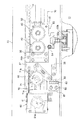
制動手段70は、図3に示すように、回転可能に歯車71aを支持するとともに該歯車71aの回転抵抗を調整可能にした本体部71と、歯車71aに噛み合うラック72とを備え、本体部71を、開閉体10によって開閉される通路用開口部の上方であって吊車支持ブラケット50と一体の取付ブラケット57の閉鎖方向側に固定し、ラック72を不動部位であるレール部材30に固定している。
本体部71内には、回転抵抗を有する状態で歯車71aが支持され、本体部71中心部には、前記回転抵抗を調整するための調整用ツマミ71bが露出している。
As shown in FIG. 3, the braking means 70 includes a
A
また、ラック72は、歯車71aと噛み合うようにして、レール部材30と略平行に配置される。このラック72には、止着具(例えばネジやボルト等)が挿通され、該止着具に螺合されたナット状部材(図示せず)が、レール部材30の被嵌合レール32aに、通路用開口部幅方向へ移動可能に嵌合されている。
よって、前記止着具を緩めて、ラック72を通路用開口部幅方向へ移動させれば、開閉体10が閉鎖動作時に減速を開始するタイミングを容易にずらすことができる。すなわち、例えば、ラック72を開放方向側にずらして固定すれば、開閉体10が閉鎖動作時に減速を開始する位置を全開位置に近い位置とすることができ、ラック72を閉鎖方向側にずらして固定すれば、開閉体10が閉鎖動作時に減速を開始する位置を全閉位置に近い位置とすることができる。
The
Therefore, if the fastening tool is loosened and the
磁性吸引体80は、開閉体全閉時の吊車支持ブラケット50よりも閉鎖方向側の不動部位(図示例によれば上枠部23)に固定され、隙間を置いた状態で吊車支持ブラケット50を吸引する。
詳細に説明すれば、磁性吸引体80は、上枠部23に固定される略L字状のブラケット81と、該ブラケット81に固定された永久磁石82と、該永久磁石82の開放方向側の面を覆って万が一の当接を阻む緩衝部材83(例えば、ゴム板等)からなり、被吸引体58との間に吸引力が作用する程度を隙間を置いた状態で、上枠部23に固定されている。
The
More specifically, the magnetic attracting
係脱部材90は、レール部材30の被嵌合レール32aの全開寄りに配置され、レール部材30に通路用開口部幅方向へ移動可能に固定された支持ブラケット91と、該支持ブラケットに止着固定された係脱弾性片92とから構成される。
支持ブラケット91には、止着具(例えば、ネジやボルト等)が挿通され、該止着具に螺合されたナット状部材(図示せず)が、係脱部材90の長手方向の端部から被嵌合レール32aに挿入されて通路用開口部幅方向へ移動可能に嵌合し、前記止着具の締め付けにより固定されている。
係脱弾性片92は、板バネ材等の弾性的に撓むことが可能な金属板材により形成され、吊車支持ブラケット50側の被掛止部56aに掛止可能な逆さへ字状の掛止部92aを有する。この掛止部92aは、図示例によれば、開放方向が逆の吊戸装置にも適用可能なように、左右対称に二つ設けられている。
上記構成の係脱部材90は、前記止着具を緩めることで、通路用開口部幅方向(図2によれば左右方向)へ移動することが可能である。例えば、係脱部材90を図2に示す位置よりも閉鎖方向側へ移動して固定すれば、開閉体10が全開した時の通路用開口部の幅を狭くすることができる。
The engaging / disengaging
A fastener (for example, a screw or a bolt) is inserted into the
The engagement / disengagement
The engaging / disengaging
次に上記構成の吊戸装置1を現場の躯体開口部に装着する手順について説明する。
先ず、建築物等の躯体開口部に枠体20が装着され固定される。
そして、上枠部23の表面カバーを外した状態で、レール部材30のレール状突起31aに、開閉体10上端側の吊車40が嵌め合せられる。この際、吊車支持ブラケット50に対し、連結プレート56、被掛止部56a、取付ブラケット57、制動手段70の本体部71、及び被吸引体58等は予め固定されているが、外れ防止部材55は分離した状態である。
次に、吊車支持ブラケット50の開放方向側の補強部52に、外れ防止部材55が止着される。この際、外れ防止部材55は、切欠部55bによりレール状突起31aを囲むようにして装着される。
この組立方法によれば、吊車支持ブラケット50の切欠部55bとレール部材30のレール状突起31aとの隙間を比較的狭くできるので、吊車40の傾き及び脱輪等を効果的に防ぐことができる。
Next, a procedure for mounting the hanging
First, the
Then, the
Next, the
According to this assembling method, the gap between the
また、上記構成の吊戸装置1は、以下に示す作用効果を奏する。
開閉体10の全閉状態又は途中閉鎖状態等において、開閉体10に対し通路用開口部貫通方向の一方側から物体が当接したり、開閉体10が風圧等を受けたり等して、開閉体10及び該開閉体10上端側の吊車支持ブラケット50が傾き、その傾きが第1の所定角度α1となった場合には、先ず、図6(b)に示すように、レール部材30の下面にローラ54が当接することで、前記傾きが抑制される。
Moreover, the hanging
When the opening /
さらに、開閉体10が通路用開口部貫通方向の一方側から受ける力が大きく、ローラ54の基端側(軸支部分)が変形や破損等し、前記傾きが第2の所定角度α2となった場合には、図6(c)に示すように、吊車支持ブラケット50における外れ防止部材55の第四の内縁55b4が、レール部材30の下端面に当接することで、前記傾きが抑制されるとともに、吊車支持ブラケット50がレール部材30から脱落するようなことを防ぐことができる。
すなわち、例えば、傾いた吊車40がレール状突起31aから外れそうになったとしても、切欠部55bの第三の内縁55b3が、レール状突起31aの内側面に当たるため、吊車40の脱輪を防ぐことができる。
Further, the force received by the opening /
That is, for example, even if the
また、外れ防止部材55を、レール部材30の長手方向に対し直交させて吊車支持ブラケット50の補強部52に重ね合わせ固定しているため、該外れ防止部材55が前記当接の際の衝撃で変形したり外れたりするようなことを効果的に防ぐことができる。
In addition, since the
また、開閉体10の閉鎖速度を変えるために、付勢手段60や制動手段70を調整する場合には、その調整作業を、通路用開口部側(図1の左側)から行うことができ、その作業性及びメンテナンス性が良好な上、開閉体10の閉鎖動作も付勢手段60による閉鎖方向側からの牽引によりスムーズに行われる。
Further, when adjusting the biasing means 60 and the braking means 70 in order to change the closing speed of the opening and closing
また、閉鎖動作した際の開閉体10が、全閉位置を通り過ぎて、開口部交差方向へ回動してしまうようなことを、磁性吸引体80の吸引力により防ぐことができる。
Further, it is possible to prevent the magnetic attracting
また、製造時やメンテナンス時に、吊車支持ブラケット50に対し、制動手段70の本体部71や被吸引体58等を装着する作業は、制動手段70の本体部71、被吸引体58及び取付ブラケット57等を一体的に扱うことができ、その作業性が良好である。
Further, the work of mounting the
また、制動手段70による減速開始位置を変えるために、ラック72を通路用開口部幅方向へずらす作業や、開閉体10の全開位置を変えるために係脱部材90を通路用開口部幅方向へずらす作業も、上述したラック72とレール部材30の嵌合構造、及び係脱部材90とレール部材30の嵌合構造によって容易に行うことができる。
Further, in order to change the deceleration start position by the braking means 70, the
なお、上記実施例によれば、特に組立性及び強度的に良好な態様として、吊車支持ブラケット50に対し別体の平板状の外れ防止部材55を止着したが、他例としては、吊車支持ブラケット50に対し一体的に外れ防止部材を加工した構成や、外れ防止部材55をブロック状に形成した態様等とすることも可能である。
In addition, according to the said Example, as a mode with especially favorable assembly property and intensity | strength, although the separate flat plate-shaped
また、上記実施例によれば、特に好ましい態様として、ローラ54と外れ防止部材55の双方を設けたが、他例としては、ローラ54のみを省いた構成とすることも可能である。
Moreover, according to the said Example, although both the
また、上記実施例によれば、特に磁性吸引体80による作用を効果的に得る構成として、両開き式の折戸装置を構成したが、他例としては、片方開き式の折戸装置や、バランスドア、引戸等を構成することも可能である。
Moreover, according to the said Example, although the double-folding type folding door apparatus was comprised especially as a structure which obtains the effect | action by the
1:吊戸装置 10:開閉体
20:枠体 30:レール部材
31a:レール状突起 40:吊車
50:吊車支持ブラケット 55:外れ防止部材
55b:切欠部 55b1:第一の内縁
55b2:第二の内縁 55b3:第三の内縁
55b4:第四の内縁 56a:被掛止部
60:付勢手段(リール装置) 61a:調整用ダイアル
62:ワイヤ 70;制動手段
71:本体部 71a:歯車
71b:調整用ツマミ 72:ラック
80:磁性吸引体 90:係脱部材
DESCRIPTION OF SYMBOLS 1: Suspension door apparatus 10: Opening and closing body 20: Frame body 30:
Claims (6)
前記制動手段は、回転可能に歯車を支持するとともに該歯車の回転抵抗を調整可能にした本体部と、前記歯車に噛み合うラックとを備え、前記本体部を、通路用開口部の上方であって前記吊車支持ブラケットの前記一方向側に固定し、前記ラックを不動部位に固定したことを特徴とする吊戸装置。 A rail member that extends in the width direction of the passage opening, a suspension wheel that rolls on the rail member, a suspension vehicle support bracket that rotatably supports the suspension vehicle, and a suspension vehicle that is suspended at the lower end of the suspension vehicle support bracket An opening / closing body; and a braking means for applying resistance to the closing operation of the opening / closing body, and the opening / closing body is moved while moving the suspension vehicle and the suspension vehicle support bracket in one direction along the rail member by an urging force of the urging device. In the sliding door device adapted to be closed,
The braking means includes a main body portion that rotatably supports a gear and adjusts the rotation resistance of the gear, and a rack that meshes with the gear, and the main body portion is located above the passage opening. A hanging door device, wherein the hanging vehicle support bracket is fixed to the one-direction side, and the rack is fixed to a stationary part.
開閉体全閉時の前記吊車支持ブラケットよりも前記一方向側の不動部位には、隙間を置いた状態で前記吊車支持ブラケットを吸引する磁性吸引体が設けられ、
前記取付ブラケットには、前記磁性吸引体によって吸引される被吸引体が固定されていることを特徴とする請求項3乃至5何れか1項記載の吊戸装置。 The opening / closing body constitutes a double door that is suspended in the suspension vehicle support bracket and rotates in both directions intersecting the opening while moving in the width direction of the opening for the passage,
A magnetic suction body that attracts the suspension vehicle support bracket in a state where a gap is provided is provided at the immovable portion on the one direction side relative to the suspension vehicle support bracket when the opening / closing body is fully closed,
The suspension door device according to any one of claims 3 to 5, wherein an attracted body to be attracted by the magnetic attracting body is fixed to the mounting bracket.
Priority Applications (1)
| Application Number | Priority Date | Filing Date | Title |
|---|---|---|---|
| JP2013145747A JP6335446B2 (en) | 2013-07-11 | 2013-07-11 | Hanging door device |
Applications Claiming Priority (1)
| Application Number | Priority Date | Filing Date | Title |
|---|---|---|---|
| JP2013145747A JP6335446B2 (en) | 2013-07-11 | 2013-07-11 | Hanging door device |
Publications (2)
| Publication Number | Publication Date |
|---|---|
| JP2015017444A true JP2015017444A (en) | 2015-01-29 |
| JP6335446B2 JP6335446B2 (en) | 2018-05-30 |
Family
ID=52438680
Family Applications (1)
| Application Number | Title | Priority Date | Filing Date |
|---|---|---|---|
| JP2013145747A Active JP6335446B2 (en) | 2013-07-11 | 2013-07-11 | Hanging door device |
Country Status (1)
| Country | Link |
|---|---|
| JP (1) | JP6335446B2 (en) |
Citations (5)
| Publication number | Priority date | Publication date | Assignee | Title |
|---|---|---|---|---|
| JP2007277845A (en) * | 2006-04-04 | 2007-10-25 | Bunka Shutter Co Ltd | Opening and closing door device |
| JP2008025239A (en) * | 2006-07-21 | 2008-02-07 | Ykk Ap株式会社 | Fittings |
| JP2010133221A (en) * | 2008-10-29 | 2010-06-17 | Daiken Co Ltd | Sliding door device |
| JP2010144474A (en) * | 2008-12-22 | 2010-07-01 | Bunka Shutter Co Ltd | Folding door device |
| JP2013112952A (en) * | 2011-11-28 | 2013-06-10 | Comany Inc | Sliding door apparatus making sliding door closed at constant speed |
-
2013
- 2013-07-11 JP JP2013145747A patent/JP6335446B2/en active Active
Patent Citations (5)
| Publication number | Priority date | Publication date | Assignee | Title |
|---|---|---|---|---|
| JP2007277845A (en) * | 2006-04-04 | 2007-10-25 | Bunka Shutter Co Ltd | Opening and closing door device |
| JP2008025239A (en) * | 2006-07-21 | 2008-02-07 | Ykk Ap株式会社 | Fittings |
| JP2010133221A (en) * | 2008-10-29 | 2010-06-17 | Daiken Co Ltd | Sliding door device |
| JP2010144474A (en) * | 2008-12-22 | 2010-07-01 | Bunka Shutter Co Ltd | Folding door device |
| JP2013112952A (en) * | 2011-11-28 | 2013-06-10 | Comany Inc | Sliding door apparatus making sliding door closed at constant speed |
Also Published As
| Publication number | Publication date |
|---|---|
| JP6335446B2 (en) | 2018-05-30 |
Similar Documents
| Publication | Publication Date | Title |
|---|---|---|
| US6983512B2 (en) | Movable door mounting assembly with trolley locking structure | |
| JP5484479B2 (en) | Elevator door engagement device | |
| KR101673338B1 (en) | Locking device for vehicle sliding door | |
| JP6815018B2 (en) | Guide device for sliding doors | |
| US20090139050A1 (en) | Door stop apparatus | |
| EP3049594B1 (en) | Telescopic pole for supporting a curtain enclosure | |
| JP6335446B2 (en) | Hanging door device | |
| JP5015483B2 (en) | Opening / closing door device | |
| JP4300434B2 (en) | Door-to-door | |
| JP5997739B2 (en) | Sliding door structure for vehicles | |
| JP6226595B2 (en) | Suspended door device and method for manufacturing the suspended door device | |
| JPH0632148Y2 (en) | Pachinko machine front frame support | |
| JP5483551B2 (en) | Door rail cleaning device | |
| RU2684827C2 (en) | Door mounting assembly with vehicle compartment, vehicle interior console and vehicle interior compartment assembly | |
| JP3704136B2 (en) | Slide rail device for upper sliding door | |
| JP5219347B2 (en) | Switchgear | |
| AU2017244844B2 (en) | Shield device and roll screen | |
| JP4850921B2 (en) | Frame structure of sliding door device | |
| JP5330848B2 (en) | Opening and closing device of double swing type hanging door | |
| JP2012117240A (en) | Fitting | |
| JP5927709B1 (en) | Stopper and stopper system | |
| JP6029392B2 (en) | Door body stop device for switchgear | |
| JP2007035744A (en) | Panel opening and closing mechanism | |
| JP3023368U (en) | Mounting structure of braking device in sliding door | |
| JP4683422B2 (en) | Joinery |
Legal Events
| Date | Code | Title | Description |
|---|---|---|---|
| A621 | Written request for application examination |
Free format text: JAPANESE INTERMEDIATE CODE: A621 Effective date: 20160603 |
|
| A977 | Report on retrieval |
Free format text: JAPANESE INTERMEDIATE CODE: A971007 Effective date: 20170227 |
|
| A131 | Notification of reasons for refusal |
Free format text: JAPANESE INTERMEDIATE CODE: A131 Effective date: 20170307 |
|
| A521 | Request for written amendment filed |
Free format text: JAPANESE INTERMEDIATE CODE: A523 Effective date: 20170428 |
|
| A131 | Notification of reasons for refusal |
Free format text: JAPANESE INTERMEDIATE CODE: A131 Effective date: 20170919 |
|
| A521 | Request for written amendment filed |
Free format text: JAPANESE INTERMEDIATE CODE: A523 Effective date: 20171107 |
|
| TRDD | Decision of grant or rejection written | ||
| A01 | Written decision to grant a patent or to grant a registration (utility model) |
Free format text: JAPANESE INTERMEDIATE CODE: A01 Effective date: 20180403 |
|
| A61 | First payment of annual fees (during grant procedure) |
Free format text: JAPANESE INTERMEDIATE CODE: A61 Effective date: 20180501 |
|
| R150 | Certificate of patent or registration of utility model |
Ref document number: 6335446 Country of ref document: JP Free format text: JAPANESE INTERMEDIATE CODE: R150 |
|
| R250 | Receipt of annual fees |
Free format text: JAPANESE INTERMEDIATE CODE: R250 |
|
| R250 | Receipt of annual fees |
Free format text: JAPANESE INTERMEDIATE CODE: R250 |