JP2015016609A - Tire vulcanizing mold and tire manufacturing method - Google Patents
Tire vulcanizing mold and tire manufacturing method Download PDFInfo
- Publication number
- JP2015016609A JP2015016609A JP2013144511A JP2013144511A JP2015016609A JP 2015016609 A JP2015016609 A JP 2015016609A JP 2013144511 A JP2013144511 A JP 2013144511A JP 2013144511 A JP2013144511 A JP 2013144511A JP 2015016609 A JP2015016609 A JP 2015016609A
- Authority
- JP
- Japan
- Prior art keywords
- housing
- tire
- molding surface
- stem
- exhaust passage
- Prior art date
- Legal status (The legal status is an assumption and is not a legal conclusion. Google has not performed a legal analysis and makes no representation as to the accuracy of the status listed.)
- Granted
Links
- 238000004519 manufacturing process Methods 0.000 title claims abstract description 7
- 238000000465 moulding Methods 0.000 claims abstract description 80
- 238000000034 method Methods 0.000 claims abstract description 6
- 238000004073 vulcanization Methods 0.000 claims description 25
- 230000000994 depressogenic effect Effects 0.000 claims description 6
- 229910052751 metal Inorganic materials 0.000 claims description 3
- 239000002184 metal Substances 0.000 claims description 3
- 238000010438 heat treatment Methods 0.000 claims 1
- 230000007257 malfunction Effects 0.000 abstract description 8
- 238000005096 rolling process Methods 0.000 description 7
- 230000006866 deterioration Effects 0.000 description 6
- 239000000463 material Substances 0.000 description 6
- 229910052782 aluminium Inorganic materials 0.000 description 3
- XAGFODPZIPBFFR-UHFFFAOYSA-N aluminium Chemical compound [Al] XAGFODPZIPBFFR-UHFFFAOYSA-N 0.000 description 3
- 238000013459 approach Methods 0.000 description 3
- 210000000988 bone and bone Anatomy 0.000 description 3
- 239000011324 bead Substances 0.000 description 2
- 230000000694 effects Effects 0.000 description 2
- 229910000838 Al alloy Inorganic materials 0.000 description 1
- 229910018134 Al-Mg Inorganic materials 0.000 description 1
- 229910018131 Al-Mn Inorganic materials 0.000 description 1
- 229910018125 Al-Si Inorganic materials 0.000 description 1
- 229910018182 Al—Cu Inorganic materials 0.000 description 1
- 229910018467 Al—Mg Inorganic materials 0.000 description 1
- 229910018464 Al—Mg—Si Inorganic materials 0.000 description 1
- 229910018461 Al—Mn Inorganic materials 0.000 description 1
- 229910018520 Al—Si Inorganic materials 0.000 description 1
- 229910018571 Al—Zn—Mg Inorganic materials 0.000 description 1
- 229910000831 Steel Inorganic materials 0.000 description 1
- 230000015572 biosynthetic process Effects 0.000 description 1
- 230000006835 compression Effects 0.000 description 1
- 238000007906 compression Methods 0.000 description 1
- 238000011156 evaluation Methods 0.000 description 1
- 150000002739 metals Chemical class 0.000 description 1
- 238000012986 modification Methods 0.000 description 1
- 230000004048 modification Effects 0.000 description 1
- 230000002093 peripheral effect Effects 0.000 description 1
- 102200082816 rs34868397 Human genes 0.000 description 1
- 239000010935 stainless steel Substances 0.000 description 1
- 229910001220 stainless steel Inorganic materials 0.000 description 1
- 239000010959 steel Substances 0.000 description 1
- 230000003746 surface roughness Effects 0.000 description 1
- XLYOFNOQVPJJNP-UHFFFAOYSA-N water Substances O XLYOFNOQVPJJNP-UHFFFAOYSA-N 0.000 description 1
Images


Classifications
-
- B—PERFORMING OPERATIONS; TRANSPORTING
- B29—WORKING OF PLASTICS; WORKING OF SUBSTANCES IN A PLASTIC STATE IN GENERAL
- B29D—PRODUCING PARTICULAR ARTICLES FROM PLASTICS OR FROM SUBSTANCES IN A PLASTIC STATE
- B29D30/00—Producing pneumatic or solid tyres or parts thereof
- B29D30/06—Pneumatic tyres or parts thereof (e.g. produced by casting, moulding, compression moulding, injection moulding, centrifugal casting)
- B29D30/0601—Vulcanising tyres; Vulcanising presses for tyres
- B29D30/0606—Vulcanising moulds not integral with vulcanising presses
- B29D2030/0607—Constructional features of the moulds
- B29D2030/0617—Venting devices, e.g. vent plugs or inserts
Abstract
Description
本発明は、タイヤの外表面に接する成形面の排気孔にベントプラグを装着したタイヤ加硫金型と、それを用いたタイヤの製造方法とに関する。 The present invention relates to a tire vulcanization mold in which a vent plug is attached to an exhaust hole of a molding surface in contact with an outer surface of a tire, and a tire manufacturing method using the same.
タイヤの加硫成形に用いられるタイヤ加硫金型では、タイヤの外表面に接する成形面に多数の排気孔が設けられ、タイヤと成形面との間の余分な空気を外部に排出するようにしている。また、スピューと呼ばれるゴム突起の形成を低減するために、排気孔に装着されるベントプラグが公知である。特許文献1〜3には、筒状のハウジングに挿入されたステムをスプリングが付勢することで開状態となり、そのステムをタイヤの外表面が押し下げることで閉状態となるベントプラグが開示されている。
In a tire vulcanization mold used for tire vulcanization molding, a large number of exhaust holes are provided on the molding surface in contact with the outer surface of the tire so that excess air between the tire and the molding surface is discharged to the outside. ing. Also, vent plugs attached to the exhaust holes are known in order to reduce the formation of rubber protrusions called spews.
ところで、成形面の一部、例えばタイヤのトレッドの接地端近傍の所謂トレッドショルダーやサイドウォールに相当する部位には、ブラダーの膨張によって拡張変形される未加硫タイヤの外表面が成形面に対して法線方向から押し当たらない領域がある。その領域では、成形面に沿って流れる未加硫ゴムがステムに側方から接近するため、まだ完全に押し下げられていないステムがハウジング内で傾いて排気路の入口が広がり、ハウジング内へのゴムの流入により排気路が閉塞されることがあった。このようなゴム噛みが発生すると、もはや排気は不可能となり、そのベントプラグは機能不全に陥る。 By the way, on a part of the molding surface, for example, a portion corresponding to a so-called tread shoulder or sidewall in the vicinity of the grounded end of the tire tread, the outer surface of the unvulcanized tire that is expanded and deformed by the expansion of the bladder is against the molding surface. There is a region that does not push from the normal direction. In that region, the unvulcanized rubber flowing along the molding surface approaches the stem from the side, so that the stem that has not yet been fully pushed down is tilted in the housing and the inlet of the exhaust passage is expanded, and the rubber into the housing The exhaust path may be blocked due to the inflow of water. When such a rubber bite occurs, exhaust is no longer possible and the vent plug fails.
本発明は上記実情に鑑みてなされたものであり、その目的は、ゴム噛みによるベントプラグの機能不全を防いで排気性能を長時間維持できるタイヤ加硫金型と、それを用いたタイヤの製造方法を提供することにある。 The present invention has been made in view of the above circumstances, and an object of the present invention is to provide a tire vulcanization mold capable of maintaining exhaust performance for a long time by preventing malfunction of a vent plug due to rubber biting, and manufacturing a tire using the same. It is to provide a method.
上記目的は、下記の如き本発明により達成することができる。即ち、本発明に係るタイヤ加硫金型は、キャビティにセットされたタイヤの外表面に接する成形面と、前記成形面で開口する排気孔に装着されたベントプラグとを備えるタイヤ加硫金型において、前記ベントプラグが、排気路を内部に有する筒状のハウジングと、前記ハウジングに挿入され、前記排気路を開閉する弁体となるステムと、前記排気路を開放するように前記ステムを前記キャビティに向けて付勢する付勢部材とを備え、前記ステムが、前記ハウジングの軸方向に延びる柱状の胴部と、前記ハウジングの開口部の内面に接することにより前記排気路を閉鎖する頭部とを有し、前記排気孔の開口中心を通る前記成形面の法線に対して前記ハウジングの中心軸が傾斜しているものである。 The above object can be achieved by the present invention as described below. That is, a tire vulcanization mold according to the present invention includes a molding surface that is in contact with an outer surface of a tire set in a cavity, and a vent plug that is attached to an exhaust hole that is open on the molding surface. The vent plug includes a cylindrical housing having an exhaust passage therein, a stem that is inserted into the housing and serves as a valve body that opens and closes the exhaust passage, and the stem is opened to open the exhaust passage. And a head that closes the exhaust passage by contacting the inner surface of the opening of the housing with a columnar body extending in the axial direction of the housing, and a biasing member that biases toward the cavity And the central axis of the housing is inclined with respect to the normal line of the molding surface passing through the opening center of the exhaust hole.
この金型では、上記の如く成型面の法線に対してハウジングが傾斜しているため、成形面に沿って流れる未加硫ゴムがステムに真横から押し当たりにくい。その結果、ステムがハウジング内で傾くことにより排気路の入口が広がる現象が抑えられ、ゴム噛みによるベントプラグの機能不全の発生を防いで、排気性能を長時間維持できる。特に、ステムの頭部を未加硫ゴムの流れと相対する向きに傾斜させた場合には、成形面に沿って流れるゴムがステムを押し下げるように作用するため、ゴム噛みの発生を効果的に防止できる。 In this mold, since the housing is inclined with respect to the normal line of the molding surface as described above, the unvulcanized rubber flowing along the molding surface is difficult to press against the stem from the side. As a result, the phenomenon that the inlet of the exhaust passage expands due to the tilt of the stem in the housing is suppressed, the malfunction of the vent plug due to the rubber engagement is prevented, and the exhaust performance can be maintained for a long time. In particular, when the head of the stem is tilted in a direction opposite to the flow of unvulcanized rubber, the rubber flowing along the molding surface acts to push down the stem. Can be prevented.
前記ハウジングの中心軸を含む平面で切断した断面で見たときに、前記ハウジングの一方の外縁が前記成形面から陥没し、前記ハウジングの他方の外縁が前記成形面から突出しているものが好ましい。ハウジングの外縁が成形面から陥没した箇所では、その陥没箇所に未加硫ゴムが流れ込んで排気路に空気を送り込むように作用するため、排気性能を高めるうえで都合がよい。また、ハウジングの外縁が成形面から突出した箇所では、その突出に対応した窪みがタイヤ表面に形成されるため、タイヤの転がり抵抗やノイズの悪化を抑制するうえで都合がよい。 It is preferable that one outer edge of the housing is recessed from the molding surface and the other outer edge of the housing protrudes from the molding surface when viewed in a cross section cut along a plane including the central axis of the housing. At the location where the outer edge of the housing is depressed from the molding surface, the unvulcanized rubber flows into the depressed portion and acts to send air into the exhaust passage, which is convenient for improving the exhaust performance. Moreover, since the hollow corresponding to the protrusion is formed in the tire surface at the location where the outer edge of the housing protrudes from the molding surface, it is convenient for suppressing deterioration of rolling resistance and noise of the tire.
この金型では、前記ハウジングの中心軸を含む平面で切断した断面で見たときに、前記ハウジングの両方の外縁が前記成形面から突出している、または、前記ハウジングの一方の外縁が前記成形面に合致し且つ前記ハウジングの他方の外縁が前記成形面から突出しているものでもよい。タイヤ表面に凸部が形成されると、その局所的な圧縮変形によるロスや騒音の発生によって転がり抵抗やノイズが悪化する傾向にあり、特にタイヤの接地面ではその傾向が顕著である。これに対し、上記の構成によれば、ベントプラグに起因した凸部がタイヤ表面に形成されないため、タイヤの転がり抵抗やノイズの悪化を効果的に抑制できる。 In this mold, when viewed in a cross section cut by a plane including the central axis of the housing, both outer edges of the housing protrude from the molding surface, or one outer edge of the housing is the molding surface And the other outer edge of the housing may protrude from the molding surface. When convex portions are formed on the tire surface, rolling resistance and noise tend to be deteriorated due to loss and noise due to local compression deformation, and this tendency is particularly remarkable on the tire contact surface. On the other hand, according to said structure, since the convex part resulting from a vent plug is not formed in the tire surface, the rolling resistance of a tire and the deterioration of noise can be suppressed effectively.
この金型では、前記ハウジングの中心軸を含む平面で切断した断面で見たときに、前記ハウジングの両方の外縁が前記成形面から陥没している、または、前記ハウジングの一方の外縁が前記成形面から陥没し且つ前記ハウジングの他方の外縁が前記成形面に合致しているものでもよい。この場合、ベントプラグが全体的に成形面から陥没した構造となり、その陥没箇所に未加硫ゴムが流れ込んで排気路に空気を送り込むように作用するため、排気性能を高めるうえで都合がよい。 In this mold, when viewed in a cross section cut by a plane including the central axis of the housing, both outer edges of the housing are recessed from the molding surface, or one outer edge of the housing is the molding It may be recessed from the surface and the other outer edge of the housing may coincide with the molding surface. In this case, the vent plug is entirely recessed from the molding surface, and the unvulcanized rubber flows into the recessed portion and acts to send air into the exhaust passage, which is convenient for improving the exhaust performance.
この金型では、前記排気孔の開口中心を通る前記成形面の法線に対して、前記ハウジングの中心軸が2〜30度の角度で傾斜する構造が実用的である。傾斜角度が2度未満であると、ゴム噛みを防止する効果が小さくなる傾向にあり、傾斜角度が30度を超えても、それ以上の改善効果は見られない。また、傾斜角度が30度を超える場合には、排気孔の加工やベントプラグの装着に関して施工が難しくなるとともに、タイヤ表面に形成される凹凸が大きくなるために使い勝手が悪い。 In this mold, a structure in which the central axis of the housing is inclined at an angle of 2 to 30 degrees with respect to the normal line of the molding surface passing through the opening center of the exhaust hole is practical. If the inclination angle is less than 2 degrees, the effect of preventing rubber biting tends to be small, and even if the inclination angle exceeds 30 degrees, no further improvement effect is seen. In addition, when the inclination angle exceeds 30 degrees, it becomes difficult to construct the exhaust holes and vent plugs, and the unevenness formed on the tire surface becomes large, so that it is not easy to use.
前記成形面から陥没又は突出した前記ハウジングの外縁と前記成形面との間隔が、前記ハウジングの軸方向に測定して2mm以内であるものが好ましい。これにより、ベントプラグに起因してタイヤ表面に形成される凹凸が大きくなり過ぎることを防いで、タイヤ外観への影響を抑制できる。また、タイヤ表面に形成される凸部の大きさが抑えられるため、タイヤの転がり抵抗やノイズの悪化を抑制するうえで都合がよい。 It is preferable that the distance between the outer edge of the housing recessed or protruding from the molding surface and the molding surface is 2 mm or less when measured in the axial direction of the housing. Thereby, the unevenness formed on the tire surface due to the vent plug is prevented from becoming too large, and the influence on the tire appearance can be suppressed. Moreover, since the size of the convex portion formed on the tire surface is suppressed, it is convenient for suppressing deterioration of tire rolling resistance and noise.
前記ステムの頭部が、前記キャビティに向かって拡径する円錐台状に形成され、前記ハウジングの開口部の内面が、前記キャビティに向かって拡径するテーパ面で形成されているものが好ましい。かかる構成によれば、排気路が閉鎖される状態において、ハウジングの開口部に対するステムの頭部の相対位置が的確に定まる。 It is preferable that the head portion of the stem is formed in a truncated cone shape whose diameter increases toward the cavity, and the inner surface of the opening of the housing is formed by a tapered surface whose diameter increases toward the cavity. According to such a configuration, the relative position of the head portion of the stem with respect to the opening portion of the housing is accurately determined in a state where the exhaust passage is closed.
この金型では、前記排気路が閉鎖される状態にて、前記ステムの頭部の頂面が、前記ハウジングの開口部の頂面と面一に配置される、または、前記ハウジングの開口部の頂面に対して凹んでいるものが好ましい。かかる構成では、排気路が開放される状態において、ハウジングからのステムの突出が比較的小さくなる。その結果、未加硫ゴムがステムをハウジング内で傾けることにより排気路の入口が広がる現象が抑えられ、ゴム噛みによるベントプラグの機能不全を効果的に防止できる。 In this mold, the top surface of the head of the stem is disposed flush with the top surface of the opening of the housing in a state where the exhaust passage is closed, or the opening of the housing What is recessed with respect to the top surface is preferable. In such a configuration, the protrusion of the stem from the housing is relatively small when the exhaust path is opened. As a result, the phenomenon that the unvulcanized rubber tilts the stem in the housing and the inlet of the exhaust passage expands is suppressed, and the malfunction of the vent plug due to the rubber biting can be effectively prevented.
本発明に係るタイヤの製造方法は、上述したタイヤ加硫金型のキャビティに未加硫タイヤをセットし、その未加硫タイヤに加熱加圧を施して加硫を行う工程を含むものである。かかる方法によれば、上述のようにゴム噛みによるベントプラグの機能不全を防ぎ、排気性能を高めて残留空気の発生を抑えられるため、良好なタイヤ外観を得ることができる。 The tire manufacturing method according to the present invention includes the steps of setting an unvulcanized tire in the cavity of the tire vulcanization mold described above, and performing vulcanization by applying heat and pressure to the unvulcanized tire. According to such a method, as described above, the malfunction of the vent plug due to the rubber biting can be prevented, the exhaust performance can be improved, and the generation of residual air can be suppressed, so that a good tire appearance can be obtained.
以下、本発明の実施形態について図面を参照しながら説明する。図1は、タイヤ子午線断面に沿ったタイヤ加硫金型10の断面を示しており、図2,3は、その要部を拡大して示している。
Hereinafter, embodiments of the present invention will be described with reference to the drawings. FIG. 1 shows a cross section of a
図1に示すように、タイヤ加硫金型10は、キャビティ15にセットされたタイヤTの外表面に接する成形面1を備える。成形面1には、加硫成形時にタイヤと成形面1との間の余分な空気を排出するために、金型10の内部(キャビティ15)と外部とを連通させる多数の排気孔16が設けられている。図2,3に拡大して示すように、その成形面1で開口する排気孔16にベントプラグ2が装着されている。排気孔16は円形の開口を有しており、法線NLは、その排気孔16の開口中心16Cを通る成形面1の法線である。
As shown in FIG. 1, the
成形面1の素材としては、アルミニウム材が例示される。このアルミニウム材は、純アルミ系の素材のみならずアルミニウム合金を含む概念であり、例えばAl−Cu系、Al−Mg系、Al−Mg−Si系、Al−Zn−Mg系、Al−Mn系、Al−Si系が挙げられる。後述するハウジング3とステム4は、それぞれステンレスやS45Cに代表される鋼材からなることが好ましく、これらは同種金属でもよいが異種金属でも構わない。
An example of the material for the
本実施形態の金型10は、タイヤのトレッド部を成形するトレッド型部11と、タイヤのサイドウォール部を成形するサイド型部12,13と、タイヤのビード部が嵌合されるビードリング14とを備える。図示を省略しているが、トレッド型部11の内面には、タイヤのトレッド面に溝を形成するための凸状の骨部が設けられている。図1では、トレッド型部11の内面で開口する1つの排気孔16と、サイド型部13の内面で開口する1つの排気孔16を描いているが、実際には、トレッド型部11やサイド型部12の内面で開口する多数の排気孔16が設けられている。
The
図2に示すように、ベントプラグ2は、排気路21を内部に有する筒状のハウジング3と、ハウジング3に挿入され、排気路21を開閉する弁体となるステム4と、排気路21を開放するようにステム4をキャビティ15に向けて付勢する付勢部材5とを備える。排気孔16に嵌入されたハウジング3は、成形面1に対して固定されている。ハウジング3の開口部31の頂面31aは、キャビティ15に面する。ハウジング3の下端部32には、貫通孔32aと、内鍔状の支持部32bとが形成されている。
As shown in FIG. 2, the
ステム4は、ハウジング3の軸方向に延びる柱状の胴部41と、ハウジング3の開口部31の内面に接することにより排気路21を閉鎖する頭部42とを有する。胴部41の下端には、貫通孔32aより大径のストッパー43が形成され、これによりステム4がハウジング3から抜け出ない。ストッパー43は、スリット44を閉じるように弾性変形させることで、貫通孔32aを通過できる。開口部31の頂面31aと頭部42の頂面42aとは、それぞれ平面により形成されている。付勢部材5は、円柱状の胴部41を取り囲み、頭部42と支持部32bとの間に介在してステム4を付勢する。
The
図2では排気路21が開放されており、ベントプラグ2は開状態にある。ベントプラグ2が開状態にある間は、タイヤの外表面が成形面1に接近する動作に伴って、キャビティ15内の空気が排気路21を介して金型10の外部へ排出される。この排気路21は、ハウジング3の開口部31とステム4の頭部42との間、付勢部材5が取り囲むステム4の胴部41とハウジング3との間、ステム4の胴部41と貫通孔32aとの間に形成される。排気路21の入口は、開口部31の内面と頭部42の側面との間でリング状に開口する。成形面1に接するタイヤの外表面によりステム4が押し下げられると、図3のように排気路21の入口が閉じて閉鎖され、ベントプラグ2は閉状態となる。
In FIG. 2, the
この金型10では、図2,3に示すように、排気孔16の開口中心16Cを通る成形面1の法線NLに対してハウジング3の中心軸3Aが傾斜している。ハウジング3は、法線NLに対して傾斜して延びる排気孔16に沿って嵌入されている。かかる構成によれば、成形面1に沿って流れる未加硫ゴムがステム4に真横から押し当たりにくい。その結果、ステム4がハウジング3内で傾くことにより排気路21の入口が広がる現象が抑えられ、ゴム噛みによるベントプラグ2の機能不全の発生を防いで、排気性能を長時間維持できる。
In the
図2,3に示した排気孔16は、タイヤの外表面が法線方向から押し当たりにくい部位(例えばタイヤのトレッドの接地端近傍の所謂トレッドショルダーやサイドウォールに相当する部位)に含まれ、未加硫ゴムが成形面1に沿って図の右側へ流れる領域に設けられている。それを想定して、このベントプラグ2では、ステム4の頭部42を未加硫ゴムの流れと相対する向き(即ち、図の左側)に傾斜させている。かかる構成によれば、成形面1に沿って流れる未加硫ゴムがステム4を押し下げるように作用するため、ゴム噛みの発生を効果的に防止できる。
The
本発明者の知見によれば、一般的な加硫成形において、トレッドではタイヤ幅方向の中央から両外側へ向かって未加硫ゴムが流れる傾向にあり、サイドウォールではタイヤ最大幅位置付近からタイヤ径方向の両側へ向かって未加硫ゴムが流れる傾向にあることが分かっている。更に、偏平率が60%未満のタイヤでは、トレッドでのゴム流れの影響が強く、偏平率が60%を超える断面形状が丸いタイヤでは、サイドウォールでのゴム流れの影響が強い傾向にあることも分かっている。 According to the knowledge of the present inventor, in general vulcanization molding, in the tread, unvulcanized rubber tends to flow from the center in the tire width direction toward both outer sides, and in the sidewall, the tire is from the vicinity of the tire maximum width position. It has been found that unvulcanized rubber tends to flow toward both sides in the radial direction. Furthermore, tires with a flatness ratio of less than 60% have a strong influence of rubber flow at the tread, and tires with a round cross-section with a flatness ratio of more than 60% tend to have a strong influence of rubber flow at the sidewall. I know.
このため、図1のように、トレッドの接地端近傍で開口する排気孔16では、キャビティ15に向かってトレッド中央側にハウジング3を傾けることが好ましく、サイドウォールのタイヤ最大幅位置よりタイヤ径方向内側で開口する排気孔16では、キャビティ15に向かってタイヤ径方向外側にハウジング3を傾けることが好ましい。また、サイドウォールのタイヤ最大幅位置よりタイヤ径方向外側で開口する排気孔16(不図示)では、キャビティ15に向かってタイヤ径方向内側にハウジング3を傾けることが好ましい。
Therefore, as shown in FIG. 1, in the
図1では、トレッド型部11の内面に開口する排気孔16において、ハウジング3がキャビティ15に向かってトレッド中央側に傾いている。また、サイド型部13の内面では、タイヤ最大幅位置よりタイヤ径方向内側で開口する排気孔16において、ハウジング3がキャビティ15に向かってタイヤ径方向外側に傾いている。図示していないが、タイヤ最大幅位置よりタイヤ径方向外側で開口する排気孔であれば、既述のようにハウジングをキャビティに向かってタイヤ径方向内側に傾けることが好適である。サイド型部12においても、これと同様である。
In FIG. 1, the
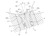
図2,3のように、ハウジング3の中心軸3Aを含む平面で切断した断面で見ると、ハウジング3の一方の外縁33aが成形面1から陥没し、ハウジング3の他方の外縁33bが成形面1から突出している。外縁33a,33bは、当該断面においてハウジング3の外周面と頂面31aとが交わる箇所である。ステム4を押し下げた状態であっても、ゴムは流れ込まないが空気が通過しうる微小隙間が開口部31に存在するため、外縁33a周辺の陥没箇所に未加硫ゴムが流れ込んだ際には、排気路21に空気を送り込むように作用し、排気性能を長時間維持できる。また、外縁33b周辺の突出に対応した窪みがタイヤ表面に形成されるため、タイヤの転がり抵抗やノイズの悪化を抑制するのに都合がよい。
As shown in FIGS. 2 and 3, when viewed in a cross section taken along a plane including the
有用な微小隙間を開口部31に形成するうえで、開口部31の内面、及び、それに接触する頭部42の側面は、それぞれ算術平均粗さRaが0.8μm以上且つ2.6μm未満となる表面粗さを有することが好ましい。これが0.8μm以上であることにより、開口部31と頭部42との接触界面に形成される微小隙間を空気が通過しやすくなり、これが2.6μm未満であることにより、その微小隙間へのゴムの流入を適切に防止できる。ゴム噛みを抑制するうえで、これらの算術平均粗さRaは1.2〜1.8μmであることがより好ましい。算術平均粗さRaはJIS B0601:2001に規定され、その評価の方式及び手順はJIS B0633:2001の規定に準拠する。
In forming a useful minute gap in the
この金型10では、実用上、成形面1の法線NLに対して、ハウジング3の中心軸3Aが2〜30度の角度で傾斜することが好ましい。即ち、傾斜角度θは2度以上が好ましく、5度以上がより好ましく、10度以上が更に好ましい。また、傾斜角度θは30度以下が好ましく、20度以下がより好ましく、15度以下が更に好ましい。
In this
成形面1から陥没したハウジング3の外縁33aと成形面1との間隔Da、及び、成形面1から突出したハウジング3の外縁33bと成形面1との間隔Dbは、それぞれ2mm以内であることが好ましく、2mm未満であることがより好ましい。間隔Da,Dbは、いずれもハウジング3の軸方向に測定される。また、間隔Da,Dbは、例えば0.3mm以上に設定される。
The distance Da between the
成形面1は、タイヤの外表面に沿って湾曲したプロファイル(輪郭)を有しており、図3では、排気孔16を通る湾曲プロファイル1aを破線で描いている。この金型10では、図3のような排気路21が閉鎖される状態にて、頭部42の頂面42aとステム4の中心軸(ハウジング3の中心軸3Aと一致)との交点45が、成形面1の湾曲プロファイル1aよりもキャビティ15側に配置されている。これにより、ベントプラグ2に起因してタイヤ表面に形成される凸部が減少し、タイヤの転がり抵抗やノイズの悪化を抑制するうえで都合がよい。
The
上述した交点45は、湾曲プロファイル1a上に配置されていてもよいし、或いは湾曲プロファイル1aよりも排気孔16側に配置されていても構わない(図5参照)。図2,3に示したような、一方の外縁33aが成形面1から陥没し、他方の外縁33bが成形面1から突出する形態においては、間隔Dcが1mm以内であることが好ましく、0.5mm以内であることがより好ましい。間隔Dcは、ハウジング3の軸方向に測定される交点45と湾曲プロファイル1aとの間隔である。
The
図2のような排気路21が開放される状態では、ステム4の頭部42の頂面42aが、少なくともその一部を湾曲プロファイル1aよりも排気孔16側に配置させていることが好ましい。それにより、成形面1に沿って流れる未加硫ゴムが、ステム4の頭部42に対して側方からではなく頂面42a側から接しやすくなり、未加硫ゴムがステム4を押し下げる作用を促進しうるため、ゴム噛みを防止するうえで有利である。
In the state where the
本実施形態では、ステム4の頭部42が、キャビティ15に向かって拡径する円錐台状に形成され、ハウジング3の開口部31の内面が、キャビティ15に向かって拡径するテーパ面で形成されている。排気路21が閉鎖される状態では、頭部42の側面が開口部31の内面に面接触する。かかる構成によれば、ハウジング3の開口部31に対するステム4の頭部42の相対位置が的確に定まる。
In the present embodiment, the
本実施形態では、排気路21が閉鎖される状態にて、ステム4の頭部42の頂面42aが、ハウジング3の開口部31の頂面31aと面一に配置されているが、頂面42aが頂面31aに対して凹んでいても構わない。かかる構成では、図2のように排気路21が開放される状態において、ハウジング3からのステム4の突出が比較的小さくなるため、ゴム噛みによるベントプラグの機能不全を防ぐうえで都合がよい。但し、これに限られるものではなく、頂面42aが頂面31aから突出していても構わない。
In the present embodiment, the
図4〜6に示す実施形態は、以下に説明する構成の他は、前述の実施形態と同様の構成であるので、共通点を省略して主に相違点について説明する。なお、前述の実施形態で説明した部材と同一の部材には、同一の符号を付し、重複した説明を省略する。 The embodiment shown in FIGS. 4 to 6 has the same configuration as that of the above-described embodiment except for the configuration described below. Therefore, the common points will be omitted and the differences will be mainly described. In addition, the same code | symbol is attached | subjected to the member same as the member demonstrated by the above-mentioned embodiment, and the overlapping description is abbreviate | omitted.
図4は、ハウジング3の中心軸3Aを含む平面で切断した断面で見たときに、ハウジング3の両方の外縁33a,33bが成形面1から突出している例である。かかる構成によれば、ベントプラグ2に起因した凸部がタイヤ表面に形成されないため、タイヤの転がり抵抗やノイズの悪化を効果的に抑制できる。かかる形態において、間隔Daは、例えば0〜0.2mmであり、間隔Dbは、例えば0.3〜1.3mmである。間隔Daが0mmであれば、ハウジング3の一方の外縁33aが成形面1に合致し、ハウジング3の他方の外縁33bが成形面1から突出した構造となる。
FIG. 4 is an example in which both
図5は、ハウジング3の中心軸3Aを含む平面で切断した断面で見たときに、ハウジング3の両方の外縁33a,33bが成形面1から陥没している例である。加硫成形時には、その陥没箇所に未加硫ゴムが流れ込んで排気路21に空気を送り込むように作用するため、排気性能を高めるうえで都合がよい。かかる形態において、間隔Daは、例えば0.3〜1.3mmであり、間隔Dbは、例えば0〜0.2mmである。間隔Dbが0mmであれば、ハウジング3の一方の外縁33aが成形面1から陥没し、ハウジング3の他方の外縁33bが成形面1に合致した構造となる。
FIG. 5 is an example in which both
図6のように、キャビティ15に向かって凸となる向きに湾曲する箇所に装着されるベントプラグ2においても、ハウジング3の中心軸3Aを法線NLに対して傾斜させることが可能である。但し、ゴム噛みによる機能不全を起こしやすいのは、前掲のようなキャビティ15に向かって凹となる向きに湾曲する箇所に装着されるベントプラグ2であるため、そのようなベントプラグ2に上記の如き傾斜構造を適用することが効果的である。
As shown in FIG. 6, also in the
前述の実施形態では、タイヤ子午線断面に沿った金型10の断面において、ハウジング3が上記の如く傾斜する例を示したが、これに限定されるものではない。例えば、ブロックなどの陸部を形成するための凹部の底面のコーナーでは、未加硫ゴムが骨部に向かって流れる傾向にあるため、そのコーナーに設けられるベントプラグにおいては、ハウジングの開口部から下端部に向かって骨部に近付くよう、成型面の法線に対してハウジングの中心軸を傾斜させてもよい。
In the above-described embodiment, the example in which the
この金型10を用いたタイヤの製造方法は、金型10のキャビティ15に未加硫タイヤをセットし、その未加硫タイヤに加熱加圧を施して加硫を行う工程を含む。タイヤは、ブラダーと呼ばれるゴムバッグの膨張によって拡張変形し、その外表面が成形面1に押し当たる。その過程で、タイヤと成形面1との間の空気は、ベントプラグ2の排気路21を通じて外部に排出される。このとき、排気孔16内の空間を吸引機により吸引し、排気性能を高めてもよい。
The method of manufacturing a tire using the
上述したタイヤ加硫金型は、排気孔とそれに装着されるベントプラグを上記の如く構成したこと以外は、通常のタイヤ加硫金型と同等であり、従来公知の形状や材質、機構などが何れも本発明に採用することができる。 The tire vulcanization mold described above is the same as an ordinary tire vulcanization mold except that the exhaust hole and the vent plug attached thereto are configured as described above, and has a conventionally known shape, material, mechanism, etc. Any of them can be employed in the present invention.
本発明は上述した実施形態に何ら限定されるものではなく、本発明の趣旨を逸脱しない範囲内で種々の改良変更が可能である。前述の実施形態では、トレッド型部と一対のサイド型部とを備えた金型構造であったが、本発明は、これに限定されず、例えばトレッド型部の中央部で上下に二分割された金型構造にも適用できる。また、前述の実施形態では、付勢部材がコイルバネであったが、これに代えて皿バネや板バネなどを利用しても構わない。 The present invention is not limited to the embodiment described above, and various improvements and modifications can be made without departing from the spirit of the present invention. In the above-described embodiment, the mold structure is provided with a tread mold part and a pair of side mold parts, but the present invention is not limited to this. For example, the mold structure is vertically divided into two at the center part of the tread mold part. Also applicable to mold structures. In the above-described embodiment, the urging member is a coil spring, but a disc spring or a leaf spring may be used instead.
1 成形面
2 ベントプラグ
3 ハウジング
3A 中心軸
4 ステム
5 付勢部材
10 タイヤ加硫金型
15 キャビティ
16 排気孔
21 排気路
31 開口部
33a 一方の外縁
33b 他方の外縁
41 胴部
42 頭部
DESCRIPTION OF
Claims (9)
前記ベントプラグが、排気路を内部に有する筒状のハウジングと、前記ハウジングに挿入され、前記排気路を開閉する弁体となるステムと、前記排気路を開放するように前記ステムを前記キャビティに向けて付勢する付勢部材とを備え、
前記ステムが、前記ハウジングの軸方向に延びる柱状の胴部と、前記ハウジングの開口部の内面に接することにより前記排気路を閉鎖する頭部とを有し、
前記排気孔の開口中心を通る前記成形面の法線に対して前記ハウジングの中心軸が傾斜していることを特徴とするタイヤ加硫金型。 In a tire vulcanization mold comprising a molding surface in contact with an outer surface of a tire set in a cavity, and a vent plug attached to an exhaust hole opened in the molding surface,
The vent plug includes a cylindrical housing having an exhaust passage therein, a stem that is inserted into the housing and serves as a valve body that opens and closes the exhaust passage, and the stem is inserted into the cavity so as to open the exhaust passage. A biasing member biasing toward the
The stem has a columnar body extending in the axial direction of the housing, and a head that closes the exhaust passage by contacting an inner surface of the opening of the housing,
A tire vulcanization mold, wherein a central axis of the housing is inclined with respect to a normal line of the molding surface passing through an opening center of the exhaust hole.
Priority Applications (2)
| Application Number | Priority Date | Filing Date | Title |
|---|---|---|---|
| JP2013144511A JP6088927B2 (en) | 2013-07-10 | 2013-07-10 | Tire vulcanization mold and tire manufacturing method |
| CN201420114622.2U CN203765842U (en) | 2013-07-10 | 2014-03-13 | Tire vulcanizing metal die |
Applications Claiming Priority (1)
| Application Number | Priority Date | Filing Date | Title |
|---|---|---|---|
| JP2013144511A JP6088927B2 (en) | 2013-07-10 | 2013-07-10 | Tire vulcanization mold and tire manufacturing method |
Publications (2)
| Publication Number | Publication Date |
|---|---|
| JP2015016609A true JP2015016609A (en) | 2015-01-29 |
| JP6088927B2 JP6088927B2 (en) | 2017-03-01 |
Family
ID=51283081
Family Applications (1)
| Application Number | Title | Priority Date | Filing Date |
|---|---|---|---|
| JP2013144511A Active JP6088927B2 (en) | 2013-07-10 | 2013-07-10 | Tire vulcanization mold and tire manufacturing method |
Country Status (2)
| Country | Link |
|---|---|
| JP (1) | JP6088927B2 (en) |
| CN (1) | CN203765842U (en) |
Cited By (3)
| Publication number | Priority date | Publication date | Assignee | Title |
|---|---|---|---|---|
| JP2017100406A (en) * | 2015-12-03 | 2017-06-08 | 東洋ゴム工業株式会社 | Mold for tire vulcanization, and method for production of tire |
| US10144188B2 (en) | 2015-12-21 | 2018-12-04 | Toyo Tire & Rubber Co., Ltd. | Tire vulcanizing mold |
| CN115103750A (en) * | 2020-03-04 | 2022-09-23 | 横滨橡胶株式会社 | Method for manufacturing and maintaining tire vulcanization mold |
Families Citing this family (2)
| Publication number | Priority date | Publication date | Assignee | Title |
|---|---|---|---|---|
| JP6600537B2 (en) * | 2015-11-19 | 2019-10-30 | 株式会社ブリヂストン | Tire vulcanization mold and manufacturing method thereof |
| JP2020066212A (en) * | 2018-10-26 | 2020-04-30 | Toyo Tire株式会社 | Vent plug, tire vulcanizing mold and method for manufacturing tire |
Citations (2)
| Publication number | Priority date | Publication date | Assignee | Title |
|---|---|---|---|---|
| JP2003340825A (en) * | 2002-05-28 | 2003-12-02 | Bridgestone Corp | Mold for vulcanizing rubber molding |
| JP2006334872A (en) * | 2005-06-01 | 2006-12-14 | Bridgestone Corp | Tire vulcanizing mold |
-
2013
- 2013-07-10 JP JP2013144511A patent/JP6088927B2/en active Active
-
2014
- 2014-03-13 CN CN201420114622.2U patent/CN203765842U/en not_active Expired - Lifetime
Patent Citations (2)
| Publication number | Priority date | Publication date | Assignee | Title |
|---|---|---|---|---|
| JP2003340825A (en) * | 2002-05-28 | 2003-12-02 | Bridgestone Corp | Mold for vulcanizing rubber molding |
| JP2006334872A (en) * | 2005-06-01 | 2006-12-14 | Bridgestone Corp | Tire vulcanizing mold |
Cited By (3)
| Publication number | Priority date | Publication date | Assignee | Title |
|---|---|---|---|---|
| JP2017100406A (en) * | 2015-12-03 | 2017-06-08 | 東洋ゴム工業株式会社 | Mold for tire vulcanization, and method for production of tire |
| US10144188B2 (en) | 2015-12-21 | 2018-12-04 | Toyo Tire & Rubber Co., Ltd. | Tire vulcanizing mold |
| CN115103750A (en) * | 2020-03-04 | 2022-09-23 | 横滨橡胶株式会社 | Method for manufacturing and maintaining tire vulcanization mold |
Also Published As
| Publication number | Publication date |
|---|---|
| JP6088927B2 (en) | 2017-03-01 |
| CN203765842U (en) | 2014-08-13 |
Similar Documents
| Publication | Publication Date | Title |
|---|---|---|
| JP6088927B2 (en) | Tire vulcanization mold and tire manufacturing method | |
| JP6706492B2 (en) | Tire vulcanization mold and method for manufacturing tire | |
| JP6646434B2 (en) | Tire vulcanization mold | |
| US10029433B1 (en) | Tire vulcanization mold and tire manufacturing method using the same | |
| JP3391756B2 (en) | Pneumatic tire | |
| JP6898828B2 (en) | Tire vulcanization mold and tire manufacturing method | |
| JP6088921B2 (en) | Tire vulcanization mold and tire manufacturing method | |
| JP6527396B2 (en) | Vent plug for tire molding mold, and tire molding mold and tire manufacturing method using the same | |
| JP2002326227A (en) | Mold for vulcanizing tire, method fr manufacturing tire, and tire | |
| KR101656345B1 (en) | Tire having rim protector | |
| JP2015051611A (en) | Tire vulcanizing mold and tire manufacturing method | |
| JP6087089B2 (en) | Vent piece for tire vulcanization mold, tire vulcanization mold and tire manufacturing method | |
| JP6059103B2 (en) | Tire vulcanization mold and tire manufacturing method | |
| JP5227266B2 (en) | Tire vulcanizing mold | |
| JP2015193176A (en) | Die and method for producing pneumatic tire | |
| JP6629585B2 (en) | Tire vulcanization mold | |
| JP2020066212A (en) | Vent plug, tire vulcanizing mold and method for manufacturing tire | |
| JP2019209488A (en) | Tire vulcanizing mold and method for manufacturing pneumatic tire | |
| JP2020066180A (en) | Vent plug, tire vulcanizing mold and method for manufacturing tire | |
| JP6663705B2 (en) | Tire mold | |
| JP2020066210A (en) | Vent plug, tire vulcanizing mold and method for manufacturing tire | |
| JP6113564B2 (en) | Tire vulcanization mold and vent plug for tire vulcanization mold used therefor | |
| JP7219670B2 (en) | tire mold | |
| JP7105565B2 (en) | Tire vulcanization mold and vent plug | |
| CN116021816A (en) | Vent plug, tire vulcanization mold, and method for manufacturing tire |
Legal Events
| Date | Code | Title | Description |
|---|---|---|---|
| A621 | Written request for application examination |
Free format text: JAPANESE INTERMEDIATE CODE: A621 Effective date: 20160318 |
|
| A977 | Report on retrieval |
Free format text: JAPANESE INTERMEDIATE CODE: A971007 Effective date: 20161102 |
|
| A131 | Notification of reasons for refusal |
Free format text: JAPANESE INTERMEDIATE CODE: A131 Effective date: 20161124 |
|
| A521 | Request for written amendment filed |
Free format text: JAPANESE INTERMEDIATE CODE: A523 Effective date: 20170105 |
|
| TRDD | Decision of grant or rejection written | ||
| A01 | Written decision to grant a patent or to grant a registration (utility model) |
Free format text: JAPANESE INTERMEDIATE CODE: A01 Effective date: 20170125 |
|
| A61 | First payment of annual fees (during grant procedure) |
Free format text: JAPANESE INTERMEDIATE CODE: A61 Effective date: 20170206 |
|
| R150 | Certificate of patent or registration of utility model |
Ref document number: 6088927 Country of ref document: JP Free format text: JAPANESE INTERMEDIATE CODE: R150 |
|
| S531 | Written request for registration of change of domicile |
Free format text: JAPANESE INTERMEDIATE CODE: R313531 |
|
| R350 | Written notification of registration of transfer |
Free format text: JAPANESE INTERMEDIATE CODE: R350 |
|
| S533 | Written request for registration of change of name |
Free format text: JAPANESE INTERMEDIATE CODE: R313533 |
|
| R350 | Written notification of registration of transfer |
Free format text: JAPANESE INTERMEDIATE CODE: R350 |
|
| R250 | Receipt of annual fees |
Free format text: JAPANESE INTERMEDIATE CODE: R250 |
|
| R250 | Receipt of annual fees |
Free format text: JAPANESE INTERMEDIATE CODE: R250 |
|
| R250 | Receipt of annual fees |
Free format text: JAPANESE INTERMEDIATE CODE: R250 |
|
| R250 | Receipt of annual fees |
Free format text: JAPANESE INTERMEDIATE CODE: R250 |
|
| R250 | Receipt of annual fees |
Free format text: JAPANESE INTERMEDIATE CODE: R250 |