JP2015016516A - Device and method for assembling workpiece - Google Patents
Device and method for assembling workpiece Download PDFInfo
- Publication number
- JP2015016516A JP2015016516A JP2013143985A JP2013143985A JP2015016516A JP 2015016516 A JP2015016516 A JP 2015016516A JP 2013143985 A JP2013143985 A JP 2013143985A JP 2013143985 A JP2013143985 A JP 2013143985A JP 2015016516 A JP2015016516 A JP 2015016516A
- Authority
- JP
- Japan
- Prior art keywords
- press
- work
- workpiece
- nut
- fitting
- Prior art date
- Legal status (The legal status is an assumption and is not a legal conclusion. Google has not performed a legal analysis and makes no representation as to the accuracy of the status listed.)
- Pending
Links
Images


Abstract
Description
本発明は、ディファレンシャルケースにリングギヤ等のワークを圧入及びボルト締めにより組付けるワークの組付け装置及び組付け方法に関する。 The present invention relates to a work assembling apparatus and method for assembling a work such as a ring gear to a differential case by press-fitting and bolting.
一般に、ディファレンシャルケース(以下デフケースという)にリングギヤを圧入してボルト締めする等の2個のワークを圧入してボルト締めするには、圧入とボルト締めの専用設備、例えば圧入には専用のサーボプレスを用いた設備、ボルト締めには専用のナットランナを用いた設備を必要として、これら2台の設備の間をワークを移動してそれぞれ作業を行っていた。 Generally, in order to press-fit two workpieces, such as press-fitting a ring gear into a differential case (hereinafter referred to as a differential case) and tighten it with bolts, special equipment for press-fitting and bolting, such as a dedicated servo press In order to tighten the bolts and bolts, a special nutrunner was required, and the work was moved between these two facilities.
従来、上記デフケースにリングギヤを組付ける専用の装置が案出されている(特許文献1)。該組付け装置は、デフケース及びリングギヤ用にそれ専用の受台(その外にデフケース両側に装着されるベアリング用の治具)を有しており、これら各受台を上下又は前後に移動するシリンダ及び所定位置にロックするシリンダを必要とし、更にボルト締め用の複数のナットランナ、ボルト頭部を保持する複数の押圧保持部及び圧入用シリンダを備えている。 Conventionally, a dedicated device for assembling a ring gear to the differential case has been devised (Patent Document 1). The assembly device has a dedicated cradle for the differential case and ring gear (a bearing jig mounted on both sides of the diff case), and a cylinder that moves the cradle up and down or back and forth. In addition, a cylinder that locks in place is required, and a plurality of nut runners for bolt tightening, a plurality of press holding portions that hold the bolt heads, and a press-fit cylinder are provided.
それぞれ専用の設備により圧入及びボルト締めする作業では、圧入及びボルト締め用の専用機を必要とし、作業面積及びコストアップになる。また、ワークをそれぞれ専用機に移動して位置決めする必要があり、生産性の向上及び労力の軽減化を妨げる原因になっている。 In the work of press-fitting and bolting with dedicated equipment, a dedicated machine for press-fitting and bolting is required, which increases the work area and cost. In addition, it is necessary to move and position the workpieces to dedicated machines, which hinders improvement in productivity and reduction in labor.
また、1台の専用機により、圧入及びボルト締めの両方を行うものでは、多数のシリンダを有する高価な専用の組付け装置が必要となり、またワーク(ディファレンシャル装置)の変更毎に面倒な段取り作業を必要とする。 In addition, if one press machine is used for both press-fitting and bolt tightening, an expensive dedicated assembly device with a large number of cylinders is required, and troublesome setup work is required each time the workpiece (differential device) is changed. Need.
そこで、本発明は、ボルト締付け用のナットランナを用いて圧入作業をも行うことにより、上述した課題を解決したワークの組付け装置及び組付け方法を提供することを目的とするものである。 Accordingly, an object of the present invention is to provide a workpiece assembling apparatus and an assembling method that solve the above-mentioned problems by performing press-fitting work using a nut runner for bolt tightening.
本発明は、ベッド(6)上に、作業位置(S)と退避位置(T)とに移動自在に支持された圧入ユニット(21)と、
前記ベッドの作業位置に対応するように配置されたボルト締付け装置(9)と、を備え、
前記ボルト締付け装置(9)は、下端に係合部を有するナットランナ(9a)を有し、
前記圧入ユニット(21)は、基台(20,31)に回転自在に支持され、前記ナットランナ(9a)の係合部に係合し得る回転軸部材(35)と、前記基台(20,31)に回転自在に支持されたナット部材(33)と、該ナット部材に螺合すると共に前記基台に回転不能かつ軸方向に移動自在に支持されたネジ軸(34)と、該ネジ軸に一体に取付けられた圧入パンチ(43)と、前記回転軸部材(35)の回転を前記ナット部材(33)に伝達する伝動手段(37,36)と、を有し、
前記ベッド(6)の作業位置(S)にセットされた第1のワーク(50)に第2のワーク(51)を載置した状態で前記作業位置(S)にある前記圧入ユニット(21)の前記回転軸部材(35)に前記ナットランナ(9a)の係合部を係合して、前記ナットランナ(9a)の回転を前記ナット部材(33)に伝達して、ネジ軸(34)を移動することにより前記圧入パンチ(43)にて前記第2のワーク(51)を前記第1のワーク(50)に圧入し、この状態で前記圧入ユニット(21)を前記退避位置(T)に移動して、前記ボルト締付け装置(9)の前記ナットランナ(9a)によりボルト(57)を締付けて前記第2のワーク(51)を前記第1のワーク(50)に固定することを特徴とする、
ワークの組付け装置にある。
The present invention includes a press-fit unit (21) supported on a bed (6) so as to be movable between a work position (S) and a retracted position (T),
A bolt tightening device (9) arranged to correspond to the working position of the bed,
The bolt tightening device (9) has a nut runner (9a) having an engaging portion at the lower end,
The press-fitting unit (21) is rotatably supported by a base (20, 31), and a rotary shaft member (35) capable of engaging with an engaging portion of the nut runner (9a), and the base (20, 31). 31) a nut member (33) rotatably supported by the nut member, a screw shaft (34) screwed to the nut member and supported by the base so as not to be rotatable and movable in the axial direction, and the screw shaft A press-fitting punch (43) integrally attached to the rotation member, and transmission means (37, 36) for transmitting the rotation of the rotary shaft member (35) to the nut member (33),
The press-fitting unit (21) in the work position (S) with the second work (51) placed on the first work (50) set in the work position (S) of the bed (6). The rotating shaft member (35) is engaged with the engaging portion of the nut runner (9a), and the rotation of the nut runner (9a) is transmitted to the nut member (33) to move the screw shaft (34). Thus, the second workpiece (51) is press-fitted into the first workpiece (50) by the press-fitting punch (43), and the press-fitting unit (21) is moved to the retracted position (T) in this state. Then, the bolt (57) is tightened by the nut runner (9a) of the bolt tightening device (9) to fix the second work (51) to the first work (50),
It is in the work assembly equipment.
例えば図1を参照して、前記ボルト締付け装置(9)は、前記ベッド(6)に対して相対的に上下方向移動可能である。 For example, referring to FIG. 1, the bolt tightening device (9) is movable in the vertical direction relative to the bed (6).
例えば図3を参照して、前記ナットランナ(9a)は、前記ネジ軸(34)の軸線を中心とした円(R)上に等間隔に配置された複数個からなり、
前記回転軸部材(35)は、前記ネジ軸(34)の軸線を中心として円(R)上に等間隔に配置された複数個からなり、
前記伝動手段は、前記各回転軸部材(35)にそれぞれ一体に回転するように設けられたギヤ(37)及び前記ナット部材(33)に一体に回転するように設けられた中心ギヤ(36)を有し、
複数の前記各ナットランナ(9a)の係合部が、それぞれ複数の前記各回転軸部材(35)の頭部に係合し、前記各ナットランナ(9a)の回転が、前記各回転軸部材、前記各ギヤ(37)及び前記中心ギヤ(36)を介して前記ナット部材(33)に伝達されてなる。
For example, referring to FIG. 3, the nut runner (9a) is composed of a plurality of parts arranged at equal intervals on a circle (R) centered on the axis of the screw shaft (34).
The rotating shaft member (35) is composed of a plurality arranged at equal intervals on a circle (R) around the axis of the screw shaft (34).
The transmission means includes a gear (37) provided to rotate integrally with the rotary shaft members (35) and a center gear (36) provided to rotate integrally with the nut member (33). Have
The engaging portions of the plurality of nut runners (9a) engage with the heads of the plurality of rotating shaft members (35), respectively, and the rotation of the nut runners (9a) It is transmitted to the nut member (33) via each gear (37) and the central gear (36).
例えば図1参照して、前記第1のワーク(50)を割出し手段(25,26)を介して前記ベッド(6)の作業位置(S)にセットし、前記ボルト締付け装置(9)によるボルト締めを、前記第2のワーク(51)を圧入した前記第1のワーク(50)を前記割出し手段(25,26)にて所定角度回転して複数回行う。 For example, referring to FIG. 1, the first work (50) is set at the work position (S) of the bed (6) via the indexing means (25, 26), and is then moved by the bolt tightening device (9). The first workpiece (50) into which the second workpiece (51) is press-fitted is rotated by a predetermined angle by the indexing means (25, 26), and then bolted a plurality of times.
例えば図1を参照して、圧入により前記圧入ユニット(21)に作用する反力を前記ベッド(6)にて受ける反力受け部材(12)を備える。 For example, with reference to FIG. 1, the reaction force receiving member (12) which receives the reaction force which acts on the said press-fit unit (21) by press-fit in the said bed (6) is provided.
前記ナットランナ(9a)の出力トルクを管理して、前記圧入ユニット(21)の圧入推力を設定してなる。これにより、ナットランナの出力トルクを管理することにより圧入ユニットの圧入推力を適切な値に容易に設定することができる。 The output torque of the nut runner (9a) is managed to set the press-fitting thrust of the press-fitting unit (21). Thereby, the press-fit thrust of the press-fit unit can be easily set to an appropriate value by managing the output torque of the nut runner.
例えば図4,図5を参照して、前記第1のワークが、ディファレンシャルケース(50)であり、前記第2のワークが、リングギヤ(51)である。 For example, referring to FIGS. 4 and 5, the first work is a differential case (50), and the second work is a ring gear (51).
例えば図6を参照して、本発明は、圧入ユニット(21)を退避位置(T)に退避した状態でベッド(6)の作業位置(S)に第1のワーク(50)及び第2のワーク(51)をセットする工程と[図6(a),(b)]、
圧入ユニット(21)を作業位置(S)に移動する工程と[図6(c)]、
ボルト締付け装置(9)のナットランナ(9a)の回転により圧入ユニット(21)を駆動して、第1のワーク(50)に第2のワーク(51)を圧入する工程と[図6(d)]、
圧入ユニット(21)を退避位置(T)に移動する工程と[図6(e)]、
ボルト締付け装置(9)によりボルトを締付けて第1のワーク(50)に第2のワーク(51)を固定する工程と[図6(f),(g)]、
を順次行うことを特徴とする、
ワークの組付け方法にある。
For example, referring to FIG. 6, in the present invention, the first work (50) and the second work are moved to the work position (S) of the bed (6) in a state where the press-fitting unit (21) is retracted to the retreat position (T). A step of setting the workpiece (51) [FIGS. 6 (a), (b)],
A step of moving the press-fitting unit (21) to the working position (S), [FIG. 6 (c)],
A step of driving the press-fitting unit (21) by the rotation of the nut runner (9a) of the bolt tightening device (9) and press-fitting the second work (51) into the first work (50) [FIG. 6 (d) ],
A step of moving the press-fitting unit (21) to the retracted position (T) [FIG. 6 (e)],
Fixing the second workpiece (51) to the first workpiece (50) by tightening the bolt with the bolt clamping device (9) [FIGS. 6 (f), (g)],
Are performed sequentially,
It is in the work assembly method.
前記ワーク組付け装置を用いて前記第1のワーク(50)に前記第2のワーク(51)を圧入し、ボルト締めしてなる。 The second workpiece (51) is press-fitted into the first workpiece (50) using the workpiece assembling apparatus and bolted.
上記カッコ内の符号は、図面と対照するためのものであるが、これにより特許請求の範囲の構成に何等影響を及ぼすものではない。 The reference numerals in the parentheses are for comparison with the drawings, but do not affect the structure of the claims.
請求項1に係る本発明によると、ボルト締付け装置のナットランナを圧入ユニットの回転軸部材に係合し、ナットランナの回転により圧入ユニットのネジ軸及び圧入パンチの移動により第2のワークを第1のワークに圧入し、かつ圧入ユニットを退避位置に退避した状態で、ボルト締付け装置によりボルトを締付けて第2のワークを第1のワークに固定することができるので、ベッドの作業位置にワークをセットした状態で、圧入とボルト締付けの両作業を行うことができ、省スペース化を図ると共に、生産性を向上でき、かつワークを移動する労力を軽減することができ、また簡単な組付け装置で足り、コストダウンを図ることができる。 According to the first aspect of the present invention, the nut runner of the bolt tightening device is engaged with the rotary shaft member of the press-fit unit, and the second workpiece is moved by the movement of the screw shaft and press-fit punch of the press-fit unit by the rotation of the nut runner. With the press-fit unit and the press-fit unit retracted to the retracted position, the bolt can be tightened with the bolt tightening device to fix the second work to the first work. In this state, both press-fitting and bolt tightening operations can be performed to save space, improve productivity, reduce the labor required to move the workpiece, and use a simple assembly device. Sufficient and cost reduction can be achieved.
請求項2に係る本発明によると、ボルト締付けをボルト締付け装置を下降して容易に行うことができ、圧入ユニットの高さ分ボルト締付け装置の下端を延ばす必要がなく、装置が簡単かつコンパクトになると共に、ボルト締付け装置のナットランナの上下動ストロークが短くて足り、圧入作業及びボルト締付け作業を効率よく行うことができる。 According to the second aspect of the present invention, bolt tightening can be easily performed by lowering the bolt tightening device, and it is not necessary to extend the lower end of the bolt tightening device by the height of the press-fitting unit, and the device is simple and compact. At the same time, the vertical stroke of the nut runner of the bolt tightening device is short, and the press-fitting operation and the bolt tightening operation can be performed efficiently.
請求項3に係る本発明によると、複数のナットランナによりネジ軸を駆動するので、簡単な装置で圧入に必要な推力を容易に得ることができる。 According to the third aspect of the present invention, since the screw shaft is driven by a plurality of nut runners, a thrust required for press-fitting can be easily obtained with a simple device.
請求項4に係る本発明によると、第2のワークを圧入した状態の第1のワークを割出し手段で所定角度回転しながら、複数回のボルト締めを行うことができ、簡単な装置でもって、第2のワークを多数のボルトにより第1のワークに固定することができる。 According to the fourth aspect of the present invention, the first work in a state where the second work is press-fitted can be bolted a plurality of times while being rotated by a predetermined angle by the indexing means, and with a simple device. The second workpiece can be fixed to the first workpiece with a large number of bolts.
請求項5に係る本発明によると、圧入に際して圧入ユニットに作用する反力を反力受け部材により受けるので、圧入時の推力は反力受け部材によりベッドに対して閉ループとなり、ワークの組付け装置の剛性を比較的低くすることが可能となって、コストダウンを図りつつ装置の信頼性の向上を図ることができる。 According to the fifth aspect of the present invention, the reaction force acting on the press-fitting unit upon press-fitting is received by the reaction force receiving member, so that the thrust at the press-fitting becomes a closed loop with respect to the bed by the reaction force receiving member, and the work assembly apparatus The rigidity of the apparatus can be made relatively low, and the reliability of the apparatus can be improved while reducing the cost.
請求項6に係る本発明によると、簡単な組付け装置でもって、ディファレンシャルケースにリングギヤを容易かつ確実に組付けることができる。 According to the sixth aspect of the present invention, the ring gear can be easily and reliably assembled to the differential case with a simple assembling apparatus.
請求項7に係る本発明によると、圧入ユニットが作業位置と退避位置との間で移動可能で、作業位置において、ボルト締付け装置のナットランナにより駆動されて、第2のワークを第1のワークに圧入することができ、上記圧入ユニットを退避位置に移動した状態でボルト締付け装置によりボルトを締付けて第2のワークを第1のワークに固定することができるので、第1のワークに第2のワークを容易かつ確実に組付けることができる。 According to the seventh aspect of the present invention, the press-fitting unit is movable between the work position and the retracted position, and is driven by the nut runner of the bolt tightening device at the work position, so that the second work becomes the first work. The second workpiece can be fixed to the first workpiece by tightening the bolt with the bolt tightening device in a state where the press-fitting unit is moved to the retracted position, and the second workpiece is fixed to the first workpiece. The work can be assembled easily and reliably.
請求項8に係る本発明によると、請求項1ないし6のいずれかのワーク組付け装置を用いて、第1のワークに第2のワークを容易かつ確実に組付けることができる。 According to the eighth aspect of the present invention, the second workpiece can be easily and reliably assembled to the first workpiece using the workpiece assembling apparatus according to any one of the first to sixth aspects.
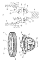
以下、図面に沿って本発明の実施の形態について説明する。ワーク組付け装置1は、図1及び図2に示すように、床2上に設置される支持台3を有し、支持台3は、足5により所定高さに水平配置されるベッド6と、該ベッド6の後側に立設されるコラム7とを有する。なお、図1において、紙面右側の作業者Mが位置する側が前側であり、紙面左側が後側であり、作業者からみて右側及び左側を左右と定義する。
Hereinafter, embodiments of the present invention will be described with reference to the drawings. As shown in FIGS. 1 and 2, the
上記コラム7は、ベッド6の作業位置Sである左側に配置されており、該コラム7に締付け装置9が配置されている。上記ベッド6上には左右方向に移動自在にテーブル10が配置されており、該テーブル10は、ベッド6の左側の作業位置Sと右側の退避位置Tとに移動し得る。ベッド6の作業位置Sには中央部にワーク受け台11が固定されており、該作業位置の前後左右の4隅には反力受け部材12が固定されている。
The
上記コラム7には上下方向に延びる平行な2本のレール13により上下方向移動自在にアーム板15が支持されていると共に、上記コラム7に締付け装置昇降用のシリンダ14が配置され、該シリンダ14のピストンが上記アーム板15に連結して、該アーム板15を上下方向に移動し得る。該アーム板15は、上記ベッド6の作業位置Sの上方に位置するように突出しており、該アーム板15には、上記締付け装置9を構成する4個のナットランナ9aが配置されている。これらナットランナ9aは、トルク管理可能なモータと、上記作業位置Sに向って延びるモータ出力軸に設けられた係合部とを有する。
An
上記ベッド6上には、上記ワーク受け台11と前後の反力受け部材12との間において左右方向に平行に延びるレール16a,16bが配置されており、上記テーブル10は、上記レール16a,16bにそれぞれ案内される摺動部材17a,17bと、これら摺動部材17a,17bの左右端に上方に延びる柱部19と、これら柱部の上端に固定される支持板20と、を有し、全体で箱形状からなる。該テーブル10の支持板20には本発明に係る圧入ユニット21が配置されている。上記ベッド6の前側にはテーブル(圧入ユニット)スライド用のシリンダ22が配置されており、該シリンダのピストン22aが上記前側の摺動部材17aにブラケットを介して連結されて、テーブル10を作業位置Sと退避位置Tとの間で移動し得る。
On the
上記ワーク受け台11は、円環状態からなり、ワークであるデフケースを支える形状からなる。該ワーク受け台11の中央部におけるベッド6上にはバックアップ台25が配置されており、該バックアップ台25はワークであるデフケースの一部に当接してワークに作用する軸方向力をベッド6で支えるように受ける。上記バックアップ台25は、ベッド6を貫通して、ベッドの裏面において割出し回転用モータ26に連結しており、該バックアップ台25は、該モータにより所定角度で割出し回転し得る。
The
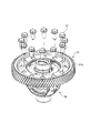
ついで、図3に沿って、圧入ユニット21について説明する。本圧入ユニット21は、上記テーブル10の該支持板20の上方において該支持板と所定間隔を保って平行になるように4本のボルト30及びナットにて一体に固定されている基板31を有しており、これら支持板20と基板31にてテーブル10と一体の基台(20,31)が構成される。基板31の中央にはベアリング32が装着されており、該ベアリング32にナット部材33が回転自在かつ軸方向移動不能に支持されている。上記ナット部材33にはネジ軸34が螺合して貫通しており、該ネジ軸の軸線を中心とした円R上に、上記支持板20と基板31とに亘って4本の回転軸部材35が回転自在にかつ軸方向移動不能に支持されている。これら回転軸部材35の上端には6角形状のボルト頭部35aが形成されている。上記ナット部材33には中心ギヤ36が一体に固定されており、また上記4本の回転軸部材35にはそれぞれキーにより一体にギヤ37が固定されており、これら各ギヤ37はそれぞれ上記中心ギヤ36に噛合している。
Next, the press-fitting
上記基板31の前後方向外側において、支持板20の左右方向中央位置に前後のポスト39が軸方向に貫通して配置される。これら両ポスト39,39は、それぞれ支持板20に固定されたハブ40に摺動自在に支持されており、これら両ポスト39,39の下端において連結プレート42が固定されている。該連結プレート42には、その中央位置に前記ネジ軸34が一体に固定されていると共に、該ネジ軸34と同軸上で連結プレート42の下方に突出して圧入パンチ43が取付けられている。
On the outer side in the front-rear direction of the
上記ポスト39の上端に固定されたストッパ41及び支持板20の下方において該ポスト39に形成された膨径部39aとの間で、一体の上記ポスト39、連結プレート42及び圧入パンチ43は、所定ストロークsで上下方向に移動し得る。
Between the
本実施の形態にあっては、圧入及びボルト締めされる2個のワークは、図4(a),(b)に示すように、ディファレンシャルケース(デフケース)50とリングギヤ51とである。デフケース50は、左右(紙面では上下)に延びる左右アクスル用円筒部50a,50bと、中央のデフギヤ収納部50cと、を有する。デフギヤ収納部50cは、デフシャフト52に支持されるデフギヤ53,53及び左右アクスル軸に連結するギヤ55,55が予め装着されている。また、デフケース50の一方のアクスル円筒部50bの外径側には軸方向に突出して環状のインロー部50d及び取付けフランジ50eが形成されており、該インロー部50dの外周面がリングギヤ51装着用の圧入面Aを形成する。リングギヤ51は、外周面にはす歯51aが形成され、内周面が上記インロー部50dに嵌合する圧入面Bとなる。
In the present embodiment, the two workpieces to be press-fitted and bolted are a differential case (difference case) 50 and a
デフケース50は、インロー部50dを上にしてその一方のアクスル用円筒部50aが上記バックアップ台25に支えられた状態で、リングギヤ51がその内周面Bをインロー部50dの外周面Aに嵌合され、上記圧入パンチ43により所定推力が作用して圧入される。なお、圧入パンチ43は、図3(b)には軸状に示されているが、ワークがリングギヤ51のように円環状の場合は、図1,図2(b)に示すように、下向きに皿状に突出する円環状部材からなるものが用いられる。
In the
上記リングギヤ51がデフケース50に圧入された後、図5に示すように、多数本、具体的には12本のボルト57がリングギヤ51の丸孔51bを通ってデフケース50の取付けフランジ50eに形成されたネジ孔50fに締付けられる。
After the
ついで、図6に沿って、前記ワークの組付け装置1を用いたデフケース50へのリングギヤ51の組付け方法について説明する。まず、図6(a)に示すように、デフケース50を組付け装置1におけるワーク受け台11にセットする。この際、デフケース50は、取付けフランジ50eが上向きになるように配置し、かつ一方のアクスル用円筒部50aをバックアップ台25が受け入れるように支え、デフケース50がバックアップ台25と一体に回転し得るように結合される。また、テーブル10及び圧入ユニット21は、退避位置Tにある。
Next, a method for assembling the
図6(b)に示すように、リングギヤ51の内周面Bがデフケース50のインロー部50dに合わさるように、リングギヤ51をデフケース50上にセットする。この際、リングギヤ51の丸孔51bがデフケース50のネジ孔50fに整合するように載置する。
As shown in FIG. 6B, the
図6(c)に示すように、圧入ユニットスライド用シリンダ22を収縮して、テーブル10を退避位置Tから作業位置Sに移動する。従って、テーブル10に一体に設けられた圧入ユニット21を作業位置Sに移動する。この際、ボルト締付け装置9は、昇降用シリンダ14により上昇位置にあり、かつデフケース50、リングギヤ51及び前後の反力受け部材12は、圧入ユニット21及びテーブル10の移動軌跡から外れる位置にあって、上記テーブル10及び圧入ユニット21の移動に干渉することはない。
As shown in FIG. 6C, the press-fitting
そして、図6(d)に示すように、昇降用シリンダ14により、ボルト締付け装置9を下降して、各(4本)ナットランナ9aの先(下)端係合部を圧入ユニット21の各(4本)回転軸部材35のボルト頭部35aに係合する。上記ナットランナ9aの先端係合部は、テーパ孔からなり、回転軸部材35の6角頭部35aに滑らかに係合する。なお、回転軸部材35のギヤ37の間にワンウェイクラッチを介在し、先端係合部と6角頭部35aの合せが困難な場合でも、回転軸部材35を一方向に回動して自動的にナットランナ9aの先端係合部に合せるようにしてもよい。
Then, as shown in FIG. 6 (d), the
この状態で、各ナットランナ9aを回転することにより各回転軸部材35を回転する。これにより、各ギヤ37及び中心ギヤ36を介してナット部材33が回転し、連結プレート42を介して廻り止めされているネジ軸34が下方に移動し、ポスト39に案内されて上記ネジ軸34と一体に圧入パンチ43が所定推力で下方に移動する。上記圧入パンチ43の推力がリングギヤ51の内周面近傍に全周に亘って略々均等に作用し、リングギヤ51は、デフケース50のインロー部50dに嵌合し、リングギヤ51の内周面Bがインロー部外周面Aに圧入されて、リングギヤ51の一側面がデフケース50の取付けフランジ50eの側面に全周に亘って当接する。上記ナットランナ9aの回転によるネジ軸34及び圧入パンチ43の移動量は、上記ポスト39の所定ストロークsにて規定され、上記圧入ストロークが設定される。
In this state, each
このようにしてリングギヤ51がデフケース50に圧入された後、ナットランナ9aは逆回転される。これにより、ナット部材33が逆回転して、ネジ軸34が上昇し、圧入ユニット21は始めの位置(上昇位置)に戻され、この状態で昇降用シリンダ14によりボルト締付け装置9を上昇する。
After the
上記圧入パンチ43によるリングギヤ51の圧入に際して、圧入ユニット21に反力が作用する。該反力は、4本の反力受け部材12の先端の突出部12aに圧入ユニット21の基台(31,20)が当接することによりベッド6により担持される。これにより、ベッド6上のバックアップ台25及び上記反力受け部材12により、リングギヤ51のデフケース50への圧入力は、閉ループで支持される。なお、圧入ユニット21の反力受けは、上記4本の柱状の反力受け部材12に限らず、テーブル10をあり溝又は丸棒のレール部材が挿通される丸孔状のガイド孔で左右方向移動自在に支持することにより反力を受けてもよい。
When the
上記圧入パンチ43の推力は、ナットランナ9aのモータの出力トルクに基づき、上記ギヤ37,36のギヤ比及びナット部材33、ネジ軸34のリード角で定まり、上記ナットランナ9aのモータの出力トルクを管理することにより上記圧入パンチ43の推力は適正に設定される。なお、ナットランナ9aは4個あるので、1個当りのナットランナ9aの出力は比較的小さくとも、圧入に必要な充分な推力は得られる。また、上記圧入パンチの推力は、ナットランナ9aのモータ出力を管理することにより行えるので、従来必要であったロードセルは、あってもよいが省略することができる。また、上記推力の設定は、モータトルクの管理に限らず、トルクリミッタを介在してもよい。
The thrust of the press-
図6(e)に示すように、シリンダ22を伸長することによりテーブル10を移動して、圧入ユニット21を退避位置Tに移動する。この状態で、図6(f)に示すように、すべて(12本)のボルト57をリングギヤ51の丸孔51b及びデフケース50のネジ孔50fに挿入する。
As shown in FIG. 6E, the table 10 is moved by extending the
そして、図6(g)に示すように、昇降用シリンダ14によりボルト締付け装置9を下降して、各(4本の)ナットランナ9aの先端係合部を4本のボルト57に合せ、各ナットランナ9aを回転することにより、4本のボルト57を締付ける。なお、各ナットランナ9aは、ボルト57の螺合による下方向移動に追従するように付勢されていることが望ましい。
Then, as shown in FIG. 6 (g), the
上記4本のボルト57の締付けが完了すると、昇降用シリンダ14によりボルト締付け装置9が上昇して、先端係合部がボルト57の係合から外れる。そして、割出し回転用モータ26を所定割出し角度(120°)回転してバックアップ台25を回転することにより、一体のデフケース50及びリングギヤ51を回転する。この状態で、昇降用シリンダ14によりボルト締付け装置9を下降して、異なる4本のボルト57にナットランナ9aの先端係合部を係合し、ナットランナ9aを回転することにより、該異なる4本のボルト57を締付ける。更に、デフケース50及びリングギヤ51を所定割出し回転した後、同様に残りの4本のボルト57を締付ける。
When the tightening of the four
これにより、リングギヤ51は、デフケース50の所定位置に圧入された後、12本のボルト57がすべて締付けられて、デフケース50に組付けられる。なお、上記実施の形態は、テーブル10及び圧入ユニット21をスライド用シリンダ22で移動しているが、作業者が手動により作業位置と退避位置とに移動してもよい。また、ワークは、上記デフケース及びリングギヤに限らず、他のものでもよい。また、ボルト締付け装置のナットランナは、4個に限らず、1個を含めて他の個数でもよい。該ナットランナの数に対して圧入ユニットの回転軸部材の数が設定されるが、必ずしも対応していなくてもよい。
Thus, after the
6 ベッド
7 コラム
9 ボルト締付け装置
9a ナットランナ
10 テーブル
12 反力受け部材
20,31 基台(支持板、基板)
21 圧入ユニット
25,26 割出し手段(バックアップ台、割出し回転用モータ)
33 ナット部材
34 ネジ軸
35 回転軸部材
36,37 伝動手段(中心ギヤ、ギヤ)
43 圧入パンチ
50 第1のワーク[ディファレンシャル(デフ)ケース]
51 第2のワーク(リングギヤ)
57 ボルト
S 作業位置
T 退避位置
R 円
6
21 Press-
33
43 Press-In
51 Second workpiece (ring gear)
57 Bolt S Work position T Retraction position R Circle
Claims (8)
前記ベッドの作業位置に対応するように配置されたボルト締付け装置と、を備え、
前記ボルト締付け装置は、下端に係合部を有するナットランナを有し、
前記圧入ユニットは、基台に回転自在に支持され、前記ナットランナの係合部に係合し得る回転軸部材と、前記基台に回転自在に支持されたナット部材と、該ナット部材に螺合すると共に前記基台に回転不能かつ軸方向に移動自在に支持されたネジ軸と、該ネジ軸に一体に取付けられた圧入パンチと、前記回転軸部材の回転を前記ナット部材に伝達する伝動手段と、を有し、
前記ベッドの作業位置にセットされた第1のワークに第2のワークを載置した状態で前記作業位置にある前記圧入ユニットの前記回転軸部材に前記ナットランナの係合部を係合して、前記ナットランナの回転を前記ナット部材に伝達して、ネジ軸を移動することにより前記圧入パンチにて前記第2のワークを前記第1のワークに圧入し、この状態で前記圧入ユニットを前記退避位置に移動して、前記ボルト締付け装置の前記ナットランナによりボルトを締付けて前記第2のワークを前記第1のワークに固定することを特徴とする、
ワークの組付け装置。 A press-fit unit supported on the bed so as to be movable between a working position and a retracted position;
A bolt tightening device arranged to correspond to the working position of the bed,
The bolt tightening device has a nut runner having an engaging portion at a lower end,
The press-fitting unit is rotatably supported by a base and can be engaged with an engaging portion of the nut runner, a nut member rotatably supported by the base, and screwed into the nut member And a screw shaft that is non-rotatably supported by the base and is movable in the axial direction, a press-fit punch that is integrally attached to the screw shaft, and a transmission means that transmits the rotation of the rotary shaft member to the nut member. And having
Engaging the engaging part of the nutrunner with the rotary shaft member of the press-fitting unit at the work position with the second work placed on the first work set at the work position of the bed; The rotation of the nut runner is transmitted to the nut member, and the screw shaft is moved to press the second workpiece into the first workpiece by the press-fitting punch. In this state, the press-fit unit is moved to the retracted position. The bolt is tightened by the nut runner of the bolt tightening device to fix the second work to the first work.
Work assembly equipment.
請求項1記載のワークの組付け装置。 The bolt tightening device is movable up and down relatively with respect to the bed;
The work assembling apparatus according to claim 1.
前記回転軸部材は、前記ネジ軸の軸線を中心として円上に等間隔に配置された複数個からなり、
前記伝動手段は、前記各回転軸部材にそれぞれ一体に回転するように設けられたギヤ及び前記ナット部材に一体に回転するように設けられた中心ギヤを有し、
複数の前記各ナットランナの係合部が、それぞれ複数の前記各回転軸部材の頭部に係合し、前記各ナットランナの回転が、前記各回転軸部材、前記各ギヤ及び前記中心ギヤを介して前記ナット部材に伝達されてなる、
請求項1又は2記載のワークの組付け装置。 The nut runner is composed of a plurality arranged at equal intervals on a circle centered on the axis of the screw shaft,
The rotating shaft member is composed of a plurality arranged at equal intervals on a circle around the axis of the screw shaft,
The transmission means includes a gear provided to rotate integrally with each rotary shaft member and a center gear provided to rotate integrally with the nut member,
The engaging portions of the plurality of nut runners engage with the heads of the plurality of rotating shaft members, respectively, and the rotation of the nut runners is performed via the rotating shaft members, the gears, and the center gear. Transmitted to the nut member,
The work assembling apparatus according to claim 1 or 2.
請求項1ないし3のいずれか記載のワークの組付け装置。 The first work is set at the working position of the bed through the indexing means, the bolt tightening by the bolt tightening device is performed, and the first work in which the second work is press-fitted is used by the indexing means. Rotate a certain angle and perform multiple times,
The work assembling apparatus according to any one of claims 1 to 3.
請求項1ないし4のいずれか記載のワークの組付け装置。 A reaction force receiving member that receives the reaction force acting on the press-fitting unit by press-fitting at the bed;
The work assembling apparatus according to any one of claims 1 to 4.
請求項1ないし5のいずれか記載のワークの組付け装置。 The first workpiece is a differential case, and the second workpiece is a ring gear.
The work assembling apparatus according to any one of claims 1 to 5.
圧入ユニットを作業位置に移動する工程と、
ボルト締付け装置のナットランナの回転により圧入ユニットを駆動して、第1のワークに第2のワークを圧入する工程と、
圧入ユニットを退避位置に移動する工程と、
ボルト締付け装置によりボルトを締付けて第1のワークに第2のワークを固定する工程と、
を順次行うことを特徴とする、
ワークの組付け方法。 Setting the first workpiece and the second workpiece at the work position of the bed in a state where the press-fitting unit is retracted to the retracted position;
Moving the press-fit unit to the working position;
Driving the press-fitting unit by rotating the nut runner of the bolt tightening device to press-fitting the second work into the first work;
Moving the press-fit unit to the retracted position;
Fixing the second workpiece to the first workpiece by tightening the bolt with a bolt clamping device;
Are performed sequentially,
How to assemble the workpiece.
請求項7記載のワークの組付け方法。 The second workpiece is press-fitted into the first workpiece using the workpiece assembling apparatus according to any one of claims 1 to 6, and bolted.
The work assembling method according to claim 7.
Priority Applications (1)
| Application Number | Priority Date | Filing Date | Title |
|---|---|---|---|
| JP2013143985A JP2015016516A (en) | 2013-07-09 | 2013-07-09 | Device and method for assembling workpiece |
Applications Claiming Priority (1)
| Application Number | Priority Date | Filing Date | Title |
|---|---|---|---|
| JP2013143985A JP2015016516A (en) | 2013-07-09 | 2013-07-09 | Device and method for assembling workpiece |
Publications (1)
| Publication Number | Publication Date |
|---|---|
| JP2015016516A true JP2015016516A (en) | 2015-01-29 |
Family
ID=52438047
Family Applications (1)
| Application Number | Title | Priority Date | Filing Date |
|---|---|---|---|
| JP2013143985A Pending JP2015016516A (en) | 2013-07-09 | 2013-07-09 | Device and method for assembling workpiece |
Country Status (1)
| Country | Link |
|---|---|
| JP (1) | JP2015016516A (en) |
Cited By (4)
| Publication number | Priority date | Publication date | Assignee | Title |
|---|---|---|---|---|
| CN106002781A (en) * | 2016-07-06 | 2016-10-12 | 广西大学 | Clamp special for disassembling differentials |
| CN110280987A (en) * | 2019-06-18 | 2019-09-27 | 湖北科峰传动设备有限公司 | A kind of combined type duplicate gear matches pressure method and tooling |
| US10766106B2 (en) | 2016-04-10 | 2020-09-08 | Toyota Motor Engineering & Manufacturing North America, Inc. | Drive shaft press |
| CN115338632A (en) * | 2022-10-17 | 2022-11-15 | 云南昆船机械制造有限公司 | Rubber ring and metal sheet integrated mounting system |
-
2013
- 2013-07-09 JP JP2013143985A patent/JP2015016516A/en active Pending
Cited By (5)
| Publication number | Priority date | Publication date | Assignee | Title |
|---|---|---|---|---|
| US10766106B2 (en) | 2016-04-10 | 2020-09-08 | Toyota Motor Engineering & Manufacturing North America, Inc. | Drive shaft press |
| CN106002781A (en) * | 2016-07-06 | 2016-10-12 | 广西大学 | Clamp special for disassembling differentials |
| CN110280987A (en) * | 2019-06-18 | 2019-09-27 | 湖北科峰传动设备有限公司 | A kind of combined type duplicate gear matches pressure method and tooling |
| CN115338632A (en) * | 2022-10-17 | 2022-11-15 | 云南昆船机械制造有限公司 | Rubber ring and metal sheet integrated mounting system |
| CN115338632B (en) * | 2022-10-17 | 2023-03-10 | 云南昆船机械制造有限公司 | Rubber ring and metal sheet integrated mounting system |
Similar Documents
| Publication | Publication Date | Title |
|---|---|---|
| CN203210001U (en) | Rotation working table and exchanging device thereof | |
| JP2015016516A (en) | Device and method for assembling workpiece | |
| CN205414944U (en) | Two fixed position rotation compact form worktable mechenism that expands | |
| CN111940788A (en) | Efficient high-accuracy drilling machine | |
| CN111958227A (en) | Automatic reducing device for screw installation | |
| CN208961432U (en) | A kind of fastener for bolt of the automobile production line with hold-down mechanism | |
| CN108637709B (en) | Improved overturning platform for machining side cover of thrust wheel | |
| CN103008718A (en) | Horizontal hole drilling device for cooling water channel of diesel engine cylinder sleeve mounting hole | |
| CN203471746U (en) | Engine disassembly and assembly overturning machine | |
| CN113732334A (en) | Chuck type clamp for fixing tool | |
| CN106513747A (en) | Rotary expansion drilling combined vertical numerical control machine tool | |
| CN113059217A (en) | Boring machine capable of machining inner hole and end face | |
| CN104669015A (en) | Machining equipment for cylindrical workpieces | |
| CN109176082B (en) | Fork truck steering axle hydro-cylinder processing frock that assembly precision is high | |
| CN111804957A (en) | Fixing device for drilling equal-division hole plate | |
| CN113909943B (en) | Indexable pressing device | |
| CN214978473U (en) | Rotary welding device for main shaft of crusher | |
| US5553525A (en) | Punch press machine | |
| CN205184275U (en) | Bloated tight clamping worktable mechenism of meshing locate mode | |
| CN205325193U (en) | Rotatory compact form worktable mechenism that expands of more positioning | |
| CN212019451U (en) | Front-end punching mechanism of multi-hole machining drilling machine | |
| CN202356940U (en) | Rapid manual holding device | |
| CN203343483U (en) | Automotive rear axle housing multi-shaft drilling device | |
| CN111805271A (en) | Clamping device for dismounting | |
| CN216940326U (en) | Cylinder sleeve clamping tool |