JP2015011981A - Illumination presentation method and illumination presentation system - Google Patents
Illumination presentation method and illumination presentation system Download PDFInfo
- Publication number
- JP2015011981A JP2015011981A JP2013139333A JP2013139333A JP2015011981A JP 2015011981 A JP2015011981 A JP 2015011981A JP 2013139333 A JP2013139333 A JP 2013139333A JP 2013139333 A JP2013139333 A JP 2013139333A JP 2015011981 A JP2015011981 A JP 2015011981A
- Authority
- JP
- Japan
- Prior art keywords
- light emission
- light emitting
- light
- control system
- data
- Prior art date
- Legal status (The legal status is an assumption and is not a legal conclusion. Google has not performed a legal analysis and makes no representation as to the accuracy of the status listed.)
- Granted
Links
- 238000000034 method Methods 0.000 title claims abstract description 46
- 238000005286 illumination Methods 0.000 title claims abstract description 21
- 230000015654 memory Effects 0.000 claims abstract description 48
- 230000005540 biological transmission Effects 0.000 claims abstract description 38
- 238000013500 data storage Methods 0.000 claims abstract description 26
- 230000000694 effects Effects 0.000 claims description 52
- 230000008569 process Effects 0.000 claims description 18
- 238000001514 detection method Methods 0.000 claims description 12
- 238000004519 manufacturing process Methods 0.000 claims description 12
- 230000004044 response Effects 0.000 abstract 1
- 238000003860 storage Methods 0.000 description 22
- 230000005855 radiation Effects 0.000 description 16
- 238000004891 communication Methods 0.000 description 9
- 238000012545 processing Methods 0.000 description 8
- 238000010586 diagram Methods 0.000 description 7
- 238000004364 calculation method Methods 0.000 description 4
- 238000004020 luminiscence type Methods 0.000 description 3
- 230000008901 benefit Effects 0.000 description 2
- 230000004397 blinking Effects 0.000 description 2
- 230000008859 change Effects 0.000 description 2
- 230000006870 function Effects 0.000 description 2
- 238000009877 rendering Methods 0.000 description 2
- 230000001360 synchronised effect Effects 0.000 description 2
- 240000004050 Pentaglottis sempervirens Species 0.000 description 1
- 235000004522 Pentaglottis sempervirens Nutrition 0.000 description 1
- 239000003086 colorant Substances 0.000 description 1
- 238000009826 distribution Methods 0.000 description 1
- 235000019557 luminance Nutrition 0.000 description 1
- 238000012986 modification Methods 0.000 description 1
- 230000004048 modification Effects 0.000 description 1
Images


Classifications
-
- F—MECHANICAL ENGINEERING; LIGHTING; HEATING; WEAPONS; BLASTING
- F21—LIGHTING
- F21L—LIGHTING DEVICES OR SYSTEMS THEREOF, BEING PORTABLE OR SPECIALLY ADAPTED FOR TRANSPORTATION
- F21L4/00—Electric lighting devices with self-contained electric batteries or cells
-
- H—ELECTRICITY
- H05—ELECTRIC TECHNIQUES NOT OTHERWISE PROVIDED FOR
- H05B—ELECTRIC HEATING; ELECTRIC LIGHT SOURCES NOT OTHERWISE PROVIDED FOR; CIRCUIT ARRANGEMENTS FOR ELECTRIC LIGHT SOURCES, IN GENERAL
- H05B45/00—Circuit arrangements for operating light-emitting diodes [LED]
- H05B45/20—Controlling the colour of the light
-
- H—ELECTRICITY
- H05—ELECTRIC TECHNIQUES NOT OTHERWISE PROVIDED FOR
- H05B—ELECTRIC HEATING; ELECTRIC LIGHT SOURCES NOT OTHERWISE PROVIDED FOR; CIRCUIT ARRANGEMENTS FOR ELECTRIC LIGHT SOURCES, IN GENERAL
- H05B47/00—Circuit arrangements for operating light sources in general, i.e. where the type of light source is not relevant
- H05B47/10—Controlling the light source
- H05B47/155—Coordinated control of two or more light sources
-
- H—ELECTRICITY
- H05—ELECTRIC TECHNIQUES NOT OTHERWISE PROVIDED FOR
- H05B—ELECTRIC HEATING; ELECTRIC LIGHT SOURCES NOT OTHERWISE PROVIDED FOR; CIRCUIT ARRANGEMENTS FOR ELECTRIC LIGHT SOURCES, IN GENERAL
- H05B47/00—Circuit arrangements for operating light sources in general, i.e. where the type of light source is not relevant
- H05B47/10—Controlling the light source
- H05B47/175—Controlling the light source by remote control
-
- F—MECHANICAL ENGINEERING; LIGHTING; HEATING; WEAPONS; BLASTING
- F21—LIGHTING
- F21S—NON-PORTABLE LIGHTING DEVICES; SYSTEMS THEREOF; VEHICLE LIGHTING DEVICES SPECIALLY ADAPTED FOR VEHICLE EXTERIORS
- F21S2/00—Systems of lighting devices, not provided for in main groups F21S4/00 - F21S10/00 or F21S19/00, e.g. of modular construction
Landscapes
- Engineering & Computer Science (AREA)
- General Engineering & Computer Science (AREA)
- Circuit Arrangement For Electric Light Sources In General (AREA)
Abstract
Description
本発明は,複数の発光装置の発光状態を制御することにより行われる照明演出方法と,この方法を実現するための照明演出システムに関する。具体的に説明すると,本発明は,例えば,コンサートや,ライブ,舞台のようなイベントで利用されるペンライト等の発光状態を制御して,ペンライトの発行による演出を行う。特に,本発明では,複数の発光装置の発光タイミングを同期して,同時に発光させることで,斬新な照明演出を行うこととしている。 The present invention relates to an illumination effect method performed by controlling light emission states of a plurality of light emitting devices, and an illumination effect system for realizing the method. More specifically, the present invention controls the light emission state of a penlight or the like used in an event such as a concert, live performance, or stage, for example, and produces an effect by issuing the penlight. In particular, in the present invention, a novel lighting effect is performed by synchronizing the light emission timings of a plurality of light emitting devices and simultaneously emitting light.
従来から,コンサートや,ライブ,舞台のようなイベントの雰囲気を盛り上げるために,様々な演出方法が用いられている。各種イベントにおける演出方法としては,例えば,音に合わせて複数のスポットライトが発光する光の色や光の照射位置を変化させる演出方法や,観客にペンライトを持たせて複数のペンライトからの発光によって所定のパターンを表現したり,表現したパターンを変化させたりする演出方法を挙げることができる。 Conventionally, various production methods have been used to enhance the atmosphere of events such as concerts, live performances, and stage performances. Examples of performance methods at various events include, for example, a production method that changes the color of light emitted by multiple spotlights and the irradiation position of light according to the sound, or a penlight that is provided to the audience. There can be mentioned a production method in which a predetermined pattern is expressed by light emission or the expressed pattern is changed.
例えば,特許文献1には,スタジアムや,スタジオ,ホールのイベント会場にいる観客にペンライトを持たせて,そのペンライトの発光状態を制御するようにした演出方法が記載されている。すなわち,特許文献1に記載の方法は,観客席を複数のブロックに分割し,各ブロックの観客が持つペンライトを各ブロック毎に異なる周波数で,点滅及び明るさに強弱をつけて発光させて演出効果を上げるようにした演出方法が記載されている。
For example,
しかしながら,特許文献1に記載された従来の演出方法は,複数のペンライトに対し,周波数の異なる電波を放射して点滅及び明るさに強弱を制御するものであるため,単調な照明演出しか行えないものであった。
However, since the conventional rendering method described in
他方,イベント会場内に存在する複数のペンライトを利用して,文字や図柄を表現するといった複雑な演出を行う場合には,例えば,ペンライトを観客に配布する前に,予めペンライトのメモリに,発光の色,タイミング,時間,強度等の発光データを記憶しておくか,又はペンライトを観客に配布した後に,観客が持つペンライトに対して発光データを無線通信によって送信し,ペンライトのメモリに記憶させる必要があると考えられる。 On the other hand, when performing a complicated performance such as expressing characters and designs using a plurality of penlights existing in the event venue, for example, before distributing the penlights to the audience, In addition, the luminescence data such as the color, timing, time, and intensity of luminescence is stored, or after the penlight is distributed to the audience, the luminescence data is transmitted to the penlight held by the audience by wireless communication. It may be necessary to store it in the memory of the light.
しかしながら,ペンライトを観客に配布する前に,各ペンライトに発光データを記憶する場合,イベントの開催期間内に,ペンライトに記憶された発光データを改変することが難しいという問題があった。例えば,イベントの種類によっては,観客の盛り上がり具合や観客の反応を見ながら,複数のペンライトを利用して表現する文字や図柄を柔軟に変更させたいという要望がある。しかし,イベント開催前に予めペンライトに発光データを記憶させてしまうと,複数のペンライトが発光するタイミングや,時間,色,強度などの発光状態が固定的なものとなってしまう。このため,ペンライトに予め発光データを記憶する態様では,イベントの内容や状況に応じて,リアルタイムに,イベントの参加者が持つペンライトの発光状態を変化させることができないないという不具合があった。 However, when light emission data is stored in each penlight before distributing the penlight to the audience, there is a problem that it is difficult to modify the light emission data stored in the penlight during the event period. For example, depending on the type of event, there is a desire to flexibly change the characters and designs expressed using a plurality of penlights while watching the audience's excitement and the audience's reaction. However, if the light emission data is stored in advance in the penlight before the event is held, the light emission state such as timing, time, color, and intensity of the plurality of penlights is fixed. For this reason, in the mode in which the light emission data is stored in the penlight in advance, there is a problem in that the light emission state of the penlight held by the event participant cannot be changed in real time according to the contents and situation of the event. .
他方,ペンライトを観客に配布した後に,各ペンライトに対して発光データを無線通信によって送信する場合,複数のペンライトを同時に発光させて,統一的な照明演出を行うことが難しいという問題がある。例えば,イベント会場としてサッカースタジアム等の広大な施設を利用する場合,そのイベント会場に配置されたペンライトの全てに対して,無線通信で発光データを送付するには,ある程度の時間が掛かる。このため,最初に発光データを受信したペンライトと最後に受信したペンライトには,発光データを受信するタイミングにタイムタグが生じること考えられる。そうすると,最初に発光データを受信したペンライトと最後に受信したペンライトが発光するタイミングを完全に同期させることが困難となる。このため,ペンライトの配布後に無線通信で発光データを送信するという態様では,例えばイベント会場全体のペンライトで一枚の図柄を表現することが完全にはできないという不具合があった。 On the other hand, when light emission data is transmitted to each penlight by wireless communication after distributing the penlight to the audience, it is difficult to perform a uniform lighting effect by simultaneously emitting a plurality of penlights. is there. For example, when a vast facility such as a soccer stadium is used as an event venue, it takes a certain amount of time to send light emission data by wireless communication to all the penlights arranged at the event venue. For this reason, it is considered that a time tag is generated at the timing of receiving the light emission data in the penlight that has received the light emission data first and the penlight that has been received last. Then, it becomes difficult to completely synchronize the timing at which the penlight that has received the light emission data first and the penlight that has been received last emit light. For this reason, in the mode in which the light emission data is transmitted by wireless communication after the distribution of the penlight, for example, there is a problem that it is not possible to completely represent one symbol with the penlight of the entire event venue.
従って,現在では,複数のペンライトによる照明演出をイベントの内容や状況に応じて柔軟に変更することができ,しかも,複数のペンライトの発光タイミングを同期させることで,文字や図柄を表現するような複雑な照明演出を行うことのできる技術が求められている。 Therefore, at present, lighting effects with multiple penlights can be flexibly changed according to the content and situation of the event, and characters and designs are expressed by synchronizing the light emission timings of multiple penlights. There is a need for a technique that can perform such complex lighting effects.
そこで,本発明の発明者は,上記の従来発明の問題点を解決する手段について鋭意検討した結果,制御システムから複数の発光装置のそれぞれに対して発光データを送信し,各発光装置において発光データを記憶しておくと共に,その後に,各発光装置の発光を開始することを希望するタイミングで,制御システムから複数の発光装置のそれぞれに対して簡単な発光開始命令を送信し,各発光装置における発光を開始させることにより,照明演出をイベントの内容や状況に応じて柔軟に変更することができ,しかも,複数の発光装置の発光タイミングを容易に同期させることができるようになるという知見を得た。そして,本発明者は,上記知見に基づけば,従来技術の課題を解決できることに想到し,本発明を完成させた。
具体的に説明すると,本発明は以下の構成を有する。
Accordingly, as a result of intensive studies on means for solving the problems of the conventional invention, the inventor of the present invention transmits light emission data to each of a plurality of light emitting devices from the control system, and the light emission data in each light emitting device. After that, at a timing when it is desired to start light emission of each light emitting device, a simple light emission start command is transmitted from the control system to each of the plurality of light emitting devices. The knowledge that lighting effects can be flexibly changed according to the contents and circumstances of the event by starting light emission, and the light emission timings of a plurality of light emitting devices can be easily synchronized. It was. The inventor has conceived that the problems of the prior art can be solved based on the above knowledge, and has completed the present invention.
More specifically, the present invention has the following configuration.
本発明の第1の側面は,照明演出方法に関する。
本発明の照明演出方法は,複数の発光装置1と,制御システム2とによって実行される。
本発明の照明演出方法では,まず,制御システム2,発光データ記憶手段21から発光データを読み出し,データ送信装置22によって,複数の発光装置1のそれぞれに対して,当該発光データを送信する。
次に,複数の発光装置1が,データ受信部11によって,制御システム2から送信された発光データを受信する。
次に,複数の発光装置1が,データ受信部11によって受信した発光データを,メモリ12に記憶する。
次に,制御システム2が,複数の発光装置1のそれぞれに対し,発光開始命令を送信する。発光開始命令は,制御システム2が備えるデータ送信装置22によって送信されるデータであってもよいし,後述する指向性信号放射装置23によって送信される指向性信号であってもよい。
次に,複数の発光装置1が,制御システム2から送信された発光開始命令を受信する。
そして,複数の発光装置1が,発光開始命令を受信した後に,メモリ12から発光データを読み出し,当該発光データに基づいて,発光部13を発光させる。
The first aspect of the present invention relates to an illumination effect method.
The lighting effect method of the present invention is executed by a plurality of
In the lighting effect method of the present invention, first, light emission data is read from the
Next, the plurality of
Next, the plurality of
Next, the
Next, the plurality of
The plurality of
上記のように,本発明においては,複数の発光装置1のそれぞれが,発光データを受信するための手段と,発光データを一時記憶するための手段と,発光開始命令を受信するための手段と,を備えている。このため,本発明では,イベントの最中であっても,各発光装置1に対してリアルタイムに発光データを送信することができる。また,本発明では,発光装置1の発光状態(色,強弱,時間等)を制御するための発光データと,発光装置1の発光開始のタイミングを制御する発光開始命令が,それぞれ異なる工程で発光装置に対して送信される。このため,発光開始命令は,発光データに比べて比較的簡単な信号とすることができる。これにより,発光開始命令を迅速に複数の発光装置1に対して送信できるようになり,各発光装置1間における発光タイミングのズレを最小限に抑えることができる。従って,本発明よれば,文字や図柄を表現するような複雑な照明演出であっても正確に行うことができるようになる。
As described above, in the present invention, each of the plurality of
本発明の照明演出方法において,発光データ及び発光開始命令は,一つのイベントの開催期間内に,制御システム2から複数の発光装置1のそれぞれに対して送信されるものであることが好ましい。
ここにいう「イベントの開催期間内」とは,例えば,発光装置1をイベントの参加者に貸与するような場合には,発光装置1を参加者に貸与してから返却されるまでの間を意味する。より具体的には,「イベントの開催期間内」とは,ライブや,コンサート,舞台が開演してから終演するまでの間を意味する。また,複数のライブやコンサートが行われるイベントの場合に,「イベントの開催期間内」とは,一つのライブやコンサートが開演してから終演するまでの間を意味している。
In the lighting effect method of the present invention, it is preferable that the light emission data and the light emission start command are transmitted from the
In this case, “within the event period” means, for example, when the
上記工程のように,本発明では,イベントの開催期間内に,複数の発光装置1に対して発光データを送信することができるため,この発光データは,イベントの内容をリアルタイムに反映したものとすることができる。例えば,発光データは,イベントの開催期間内に,制御装置1が備える発光データ作成手段26によって作成されて,発光データ記憶手段21に記憶されたものであってもよい。このため,本発明によれば,イベントの内容に応じて柔軟に発光装置1の発光状態を変化させることができる斬新な照明演出を行うことができるようになる。
As described above, in the present invention, light emission data can be transmitted to a plurality of
本発明の照明演出方法は,発光開始命令を送信する工程において,制御システム2が,指向性信号放射装置23によって,発光開始命令を,指向性信号として送信するものであってもよい。指向性信号としては,電波や,超音波,赤外線,紫外線,レーザ等を利用することができる。
また,発光開始命令を受信する工程において,複数の発光装置1の少なくとも一部は,指向性信号検出部14により,指向性信号として送信された発光開始命令を受信することとしてもよい。
In the lighting effect method of the present invention, in the step of transmitting the light emission start command, the
In the step of receiving the light emission start command, at least a part of the plurality of
上記のように,制御システム2から各発光装置1に発光開始命令を伝達する手段として,指向性信号を用いることで,例えば,イベント会場内にある複数の発光装置1の一部を発光させることができたり,複数の発光装置1を徐々に発光させていくといったような演出を簡単に行うことができる。これにより,従来にはなかった斬新な照明演出が可能となる。
As described above, by using a directional signal as means for transmitting a light emission start command from the
本発明の照明演出方法は,制御システム2が,複数の発光装置1のそれぞれが配置される位置に関する位置情報を,当該発光装置1の識別情報に関連付けて,位置情報記憶手段24に登録する位置登録工程を,さらに含むことが好ましい。
この場合に,発光データ記憶手段21には,発光装置1の配置される位置に応じて異なる複数の発光データが記憶されていることが好ましい。
また,発光データを送信する工程において,制御システム2は,位置情報記憶手段24に登録されている位置情報と識別情報に基づいて,複数の発光装置1ごとに,発光データ記憶手段21から読み出して送信する発光データを決定することが好ましい。
In the lighting effect method according to the present invention, the
In this case, it is preferable that the light emission
In the step of transmitting the light emission data, the
上記工程のように,制御システム2から各発光装置1に対して発光データを送信する前の段階で,各発光装置1の位置(参加者の座席位置等)を把握することで,例えば,複数の発光装置1の発光状態によって文字や図柄を表現するといったような複雑な照明演出を容易に行うことができる。
As in the above-described process, by knowing the position of each light-emitting device 1 (participant's seat position, etc.) before transmitting light-emission data from the
本発明の照明演出方法において,位置登録工程は,制御システム2が,読取装置25によって,イベントの開催前に,イベントの参加者に配布されたチケットに付与されている位置情報と,当該イベントの参加者に配布された発光装置1に付与されている識別情報を,読み取る工程を含むことが好ましい。さらに,位置登録工程は,制御システム2が,読取装置25によって読み取った位置情報と識別情報を関連付けて,位置情報記憶手段24に登録する工程を含むことが好ましい。
In the lighting production method of the present invention, the position registration step includes the position information given to the ticket distributed to the event participants by the
上記のように,例えば,参加者が持つチケットには,イベント会場における座席位置の情報が付与されている。また,参加者に貸与される発光装置1のそれぞれには,識別情報(ID)が付与されている。そこで,例えば,イベント会場への入場口において,参加者のチケットを確認し,その参加者に発光装置1を貸与すると共に,チケットに付与された座席位置の情報と発光装置1の識別情報を読み取って,互いに関連付けて登録しておくことができる。これにより,制御システム2は,イベントの開催期間中に,発光装置1が,イベント会場のどの位置に存在するかを把握することができる。これにより,複数の発光装置1の発光状態によって文字や図柄を表現するといったような複雑な照明演出を,より正確に行うことができるようになる。
As described above, for example, the seat position information at the event venue is given to the ticket held by the participant. Further, identification information (ID) is given to each of the
本発明の第2の側面は,照明演出システムに関する。第2の側面に係る照明演出システムは,上述した第1の側面に係る照明演出方法を実行するためのものである。
すなわち,本発明の照明演出システムは,複数の発光装置1と制御システム2を備える。
制御システム2は,
発光データ記憶手段21から読み出した発光データを,複数の発光装置1のそれぞれに対して送信するデータ送信装置22と,
発光データの送信が完了した後に,複数の発光装置1のそれぞれに対し,発光開始命令を送信する手段と,を有する。
また,発光装置1のそれぞれは,
制御システム2から送信された発光データを受信するデータ受信部11と,
データ受信部11によって受信した発光データを記憶するメモリ12と,
制御システム2から送信された発光開始命令を受信する手段と,
発光開始命令を受信した後に,メモリ12に記憶されている発光データに基づいて発光する発光部13と,を有する。
The second aspect of the present invention relates to an illumination effect system. The illumination effect system according to the second aspect is for executing the illumination effect method according to the first aspect described above.
That is, the lighting effect system of the present invention includes a plurality of light emitting
A
And means for transmitting a light emission start command to each of the plurality of light emitting
Each of the
A
A
Means for receiving a light emission start command transmitted from the
And a
本発明によれば,複数のペンライトによる照明演出をイベントの内容や状況に応じて柔軟に変更することができ,しかも,複数のペンライトの発光タイミングを同期させることで,文字や図柄を表現するような複雑な照明演出を行うことができる方法及びシステムを提供することができる。 According to the present invention, lighting effects by a plurality of penlights can be flexibly changed according to the contents and circumstances of an event, and characters and designs can be expressed by synchronizing the light emission timings of the plurality of penlights. Thus, it is possible to provide a method and a system capable of performing such a complicated lighting effect.
以下,図面を用いて本発明を実施するための形態について説明する。本発明は,以下に説明する形態に限定されるものではなく,以下の形態から当業者が自明な範囲で適宜修正したものも含む。 Hereinafter, embodiments for carrying out the present invention will be described with reference to the drawings. The present invention is not limited to the embodiments described below, but includes those appropriately modified by those skilled in the art from the following embodiments.
(1.照明演出システム)
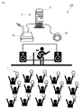
図1は,本発明における照明演出システム100の一実施形態の概要を示した全体図である。図1に示されるように,照明演出システム100は,複数の発光装置1と,各発光装置1の発光状態を制御するための制御システム2と,を備えている。
(1. Lighting effect system)
FIG. 1 is an overall view showing an outline of an embodiment of an
発光装置1は,例えば,ライブや,コンサート,舞台などのイベントの開催期間内に,イベントの参加者によって保持される装置である。発光装置1の代表例は、ペンライトである。その他,発光装置1としては,光源付きの腕輪,ネックレス,帽子,団扇,衣服などを用いることもできる。光源装置1は,イベントの参加者に対して貸与されるものであってもよいし,販売されるものであってもよい。
ただし,本発明1において,発光装置1は,イベントの参加者によって保持されるものに限られない。例えば,発光装置1は,床や路上に置かれたり,壁に掛けられたり,天井に吊るされたりして用いられる装置であってもよい。例えば,棒状の発光装置1を,床や路上に複数本設置して発光させることも可能である。
The
However, in the
制御システム2は,複数の発光装置1の発光状態を制御する。発光装置1の発光状態は,発光装置1に読み込まれる発光データによって変化する。発光データは,例えば,発光装置が発光する色,タイミング,時間,及び強度などの発光状態を制御するための情報である。制御システム2は,例えばイベントの主催者によって管理される。
The
(1−1.発光装置)
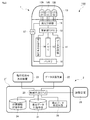
図2は,発光装置1と制御システム2の機能構成を示したブロック図である。
まず,発光装置1の各部構成について説明する。
図2に示されるように,本実施形態において,発光装置1は,制御部(CPU)10と,データ受信部11と,メモリ12と,発光部13と,指向性信号検出部14と,発光制御部15と,バッテリ16と,スイッチ17と,を備えている。
(1-1. Light Emitting Device)
FIG. 2 is a block diagram showing functional configurations of the
First, the configuration of each part of the
As shown in FIG. 2, in the present embodiment, the
発光装置1の制御部10は,メモリ12に記憶されたメインプログラムを読み出し,このプログラムに従って,データ受信部11,指向性信号検出部14,及び発光制御部15等の制御を行う。制御部10は,プログラムに従って所定の演算処理を行い,演算結果をメモリ12の作業空間に書き出しながら,各種の制御処理を実行する。
The
データ受信部11は,制御システム2から送信された各種データを受信する。データ受信部11は,例えば無線LAN(Local Area Network)方式で無線通信を行うための機能を有することが好ましい。データ受信部11は,無線LAN方式で無線通信を行うための搬送波を受信するアンテナを有している。データ受信部11によって受信されるデータの例は,発光装置1における発光状態を制御するための発光データや,発光開始のタイミングを制御する発光開始命令のデータである。データ受信部11は,受信した各種のデータを,制御部10に送出する。制御部10は,データ受信部11から発光データを受け取ると,その発光データを一時的にメモリ12に記録する。また,制御部10は,データ受信部11から発光開始命令のデータを受け取ると,メモリ12から発光データを読み出し,読み出した発光データに基づいて,発光部13を発光させる命令を生成する。
The
メモリ12は,例えば,RAM(Random Access Memory)等の揮発性メモリや,ROM(Read
Only Memory)等の不揮発性メモリから構成される記憶装置である。メモリ12のうち,RAMの記憶領域には,制御システム2から受信した発光データが記憶される。また,メモリ12のうち,ROMの記憶領域には,例えば,発光装置1の識別情報(ID)などが記憶される。また,制御部10は,データ受信部11が発光データを受信した際に,メモリ12に他の発光データが既に記憶されている場合,古い発光データを消去して,新しい発光データに書き換えることが好ましい。すなわち,メモリ12には,常に最新の発光データのみが記憶されていることが好ましい。これにより,本発明では,制御システム2から送信する発光開始命令のデータを,より簡単なものとすることができる。例えば,メモリ12内に複数の発光データが蓄積されていると,発光開始命令のデータには,メモリ12に蓄積された複数の発光データのうちの一つを選択する情報を含めなければならなくなる。これに対し,メモリ12には最新の発光データのみを記憶させ,古い発光データを順番に消去することで,発光開始命令のデータのデータ量を少なくすることができる。
The
This is a storage device composed of a non-volatile memory such as “Only Memory”. In the
発光部13は,発光制御部15による制御に基づいて発光するように構成されている。図1に示されるように,発光部13は,LEDなどの発光素子13R,13G,13Bを有する。例えば,発光部13は,赤色に発光する赤色LED13R,緑色に発光する緑色LED13G,及び青色に発光する青色LED13Bをそれぞれ一又は複数個ずつ有していることが好ましい。
The
指向性信号検出部14は,制御システム2の指向性信号放射装置23から送信された指向性信号を検出する。指向性信号の例は,電波や,超音波,赤外線,紫外線,及びレーザにより伝達される信号である。特に,指向性信号は,超音波又は赤外線により伝達される信号であることが好ましい。指向性信号検出部14としては,制御システム2の指向性信号放射装置23から送信される信号の種類に応じた装置を用いればよい。すなわち,制御システム2の指向性信号放射装置23が,赤外線放射装置である場合,指向性信号検出部14としては,赤外線受信装置を用いればよい。また,制御システム2の指向性信号放射装置23が,超音波放射装置である場合,指向性信号検出部14としては,特定周波数の超音波を検出可能な超音波検出装置を用いればよい。本実施形態において,指向性信号検出部14は,制御システム2の指向性信号放射装置23を介して送信される発光開始命令の信号を受信するために利用することができる。なお,制御システム2から送信される発光開始命令をデータ受信部11によって受信する実施形態の場合,指向性信号検出部14は省略することができる。
The
発光制御部15は,制御部10によって生成された命令に従い,発光部13の各発光素子を発光させる回路である。発光制御部15は,バッテリ16及び発光部13を構成する各発光素子と電気的に接続されており,バッテリ16から供給される電力によって,発光部13を発光させる。すなわち,発光制御部15は,発光部13を構成する赤色LED13R,緑色LED13G,及び青色LED13Bを,発光データに基づく階調,タイミング,発光時間,及び発光強度で点灯させる。これにより,発光部13は,全体として,様々な輝度で,複数の色を発光させることができるようになる。また,図1に示されるように,発光装置1は,バッテリ16から発光制御部15への電力供給のON/OFFを切り替えるためのスイッチ17を有していてもよい。発光装置1の利用者は,スイッチ17をON/OFFすることで,発光装置1の点灯と消灯を切り替えることができる。
The light
(1−2.制御システム)
続いて,制御システム2の各部構成について説明する。
図2に示されるように,本実施形態において,制御システム2は,制御手段20と,発光データ記憶手段21と,データ送信装置22と,指向性信号放射装置23と,位置情報記憶手段24と,読取装置25と,発光データ作成手段26と,を備えている。本実施形態において,制御手段20と,発光データ記憶手段21と,位置情報記憶手段24と,発光データ作成手段26は,コンピュータ装置2´に包含される。コンピュータ装置2´は,一台のコンピュータによって構成されるものであってもよいし,複数台のコンピュータを有線又は無線で接続することによって構築されたものであってもよい。また,本実施形態において,データ送信装置22と,指向性信号放射装置23と,読取装置25は,コンピュータ装置2´とは別の装置として構成されており,コンピュータ装置´に対し有線又は無線で接続されている。制御システム2は,データ送信装置22と,指向性信号放射装置23と,読取装置25を,それぞれ複数台ずつ備えていてもよい。
(1-2. Control system)
Then, each part structure of the
As shown in FIG. 2, in the present embodiment, the
制御システム2の制御手段20は,メモリ(図示省略)に記憶されたメインプログラムを読み出し,このプログラムに従って,各種の構成要素21,22,23,24,25,26等の制御を行う。制御手段20は,プログラムに従って所定の演算処理を行い,演算結果をメモリの作業空間に書き出しながら,各種の制御処理を実行する。
The control means 20 of the
発光データ記憶手段21は,各発光装置1に送信するための複数の発光データを記憶しておくためのデータベースである。各発光データには,発光装置1を発光させる色,タイミング,発光時間,及び発光強度のパターンが含まれる。また,例えば,複数の発光装置1の発光を利用し,文字や図柄を表現しようとする場合,発光データ記憶手段21は,発光装置1の配置される位置に応じて異なる複数の発光データが記憶される。すなわち,舞台や,コンサート会場,スタジアム等のイベント会場における発光装置1の配置位置(参加者の座席位置)を予め想定し,その配置位置に応じて発光データが作成される。そして,各種の発光データは,発光装置1の配置位置と関連付けて,発光データ記憶手段21に記憶されている。このため,発光装置1の配置位置をキーとして発光データ記憶手段21を参照すれば,その配置位置における発光装置1に送信すべき発光データを読み出すことが可能となっている。
The light emission data storage means 21 is a database for storing a plurality of light emission data to be transmitted to each light emitting
データ送信装置22は,複数の発光装置1に対して各種のデータを送信するための端末局である。本発明において,データ送信装置22は複数台設けられていることが好ましい。データ送信装置22は,例えば無線LAN方式で無線通信を行うための搬送波を送信するアンテナを有している。データ送信装置22によって送信されるデータの例は,発光装置1における発光状態を制御するための発光データや,発光開始のタイミングを制御する発光開始命令のデータである。すなわち,制御システム2の制御手段20は,発光データ記憶手段21から特定の発光データを読み出し,データ送信装置22を介して,特定の発光装置1に対して発光データを送信する。また,制御システム2の制御システム20は,発光開始命令を生成し,データ送信装置22を介して,特定の発光装置1に対して発光開始命令をデータとして送信することができる。
The
指向性信号放射装置23は,複数の発光装置1の一部又は全部に対して指向性信号を送信するための装置である。指向性信号放射装置23としては,例えば,公知の赤外線放射装置や超音波放射装置を用いることができる。本発明において,指向性信号放射装置23は複数台設けられていることが好ましい。本実施形態において,指向性信号放射装置23は,発光装置1に対して発光開始命令を伝達するための信号を送信するために用いられる。すなわち,指向性信号放射装置23は,発光開始命令を,例えば赤外線信号又は超音波信号として,発光装置1に対して送信することができる。なお,制御システム2が光開始命令をデータ送信装置22によって送信する実施形態の場合,指向性信号放射措置23は省略することができる。
The directional
位置情報記憶手段24は,複数の発光装置1のそれぞれについて,イベント会場における配置位置に関する情報(位置情報)を記憶しておくためのデータベースである。位置情報記憶手段は,複数の発光装置1のそれぞれが配置される位置に関する位置情報を,当該発光装置1の識別情報に関連付けて記憶する。位置情報記憶手段24に発光装置1の位置情報を登録する作業は,イベントの開始前に発光装置1の配置位置が既に決定している場合には,予め各発光装置1の識別情報を,配置位置に関連付けて記憶させておけばよい。他方,例えば,イベント会場の入り口で参加者に対し発光装置1を配布するような場合には,参加者に発光装置1を受け渡す際に,参加者のチケットに記録されている座席情報と,発光装置1の惜別情報を関連付けて,位置情報記憶手段24に登録するようにすればよい。これにより,発光装置1の配置位置をキーとして位置情報記憶手段24を参照すれば,その配置位置に存在する発光装置1の識別情報を特定することができる。他方,発光装置1の識別情報をキーとして位置情報記憶手段24を参照すれば,その発光装置1がイベント会場のどの位置に存在するかを特定することができる。
The position
読取装置25は,発光装置1の位置情報と発光装置1の識別情報を制御システム2に入力するための装置である。例えば,読取装置25としては,QRコード(登録商標)やバーコードに記録された情報を読み取るためのコード読取装置を用いることができる。例えば,イベントの参加者に与えられたチケットには,座席の位置が印字されていると共に,座席の位置を記録したコードが印刷されているとする。また,イベントの参加者に配布される発光装置1には,その発光装置1の識別情報を記録したコードが印刷されているとする。このため,読取装置25を介して,チケットに印刷されたコードと,発光装置1に印刷されたコードを読み取ることにより,発光装置1の位置情報と識別情報を関連付けることができる。すなわち,発光装置1の位置情報と識別情報は関連付けて位置情報記憶手段24に登録される。なお,読取装置25は,発光装置1の位置情報と発光装置1の識別情報を手動で入力するためのキーボード等の入力装置であってもよい。
The
発光データ作成手段26は,発光データを作成するための機能をもつハードウェア及びソフトウェアにより構成される手段である。発光データ作成手段26を介して作成された発光データは,発光データ記憶手段21に記憶される。発光データ作成手段26は,例えば,発光データの作成を補助する専用のソフトウェアと,ソフトウェアを実行するのに必要な各種情報を入力するためのハードウェアによって構成されればよい。ユーザは,発光データ作成手段26を介して,イベントの開催期間中(例えばコンサートの上演中)であっても,必要な発光データを随時作成することができる。また,ユーザは,イベントの開催前に,データ作成手段26を介して,必要な発光データを予め作成しておくこととしてもよい。 The light emission data creating means 26 is a means constituted by hardware and software having a function for creating light emission data. The light emission data created via the light emission data creation means 26 is stored in the light emission data storage means 21. The light emission data creating means 26 may be constituted by, for example, dedicated software that assists in creating light emission data and hardware for inputting various information necessary for executing the software. The user can create necessary light emission data at any time through the light emission data creation means 26 even during the event period (for example, during a concert). Further, the user may create necessary light emission data in advance via the data creation means 26 before the event is held.
(2.照明演出方法)
続いて,図3〜図9を参照して,照明演出方法のフローについて説明する。
ここで説明する照明演出方法は,上述した照明演出システム100によって実行される。
(2. Lighting production method)
Next, the flow of the lighting effect method will be described with reference to FIGS.
The illumination effect method described here is executed by the
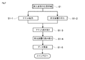
(2−1.メインフロー)
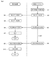
図3は,照明演出方法のメインフローを説明するためのフロー図である。
図3に示されるように,まず,制御システム2によって,複数の発光装置1それぞれの配置位置の登録処理が行われる(ステップS1)。発光装置1の位置登録処理は,制御システム2の位置情報記憶手段24に,発光装置1の配置位置に関する情報(例えば座席番号)と,発光装置1の識別情報(ID)を関連付けることにより行われる。これにより,制御システム2は,どの発光装置1がどの位置に配置されたのかを把握することができるようになる。発光装置1の位置登録処理は,キーボードなどを介して手作業で行うこととしてもよいし,後述するように,制御システム2が備える読取装置25を利用して行うこととしてもよい。発光装置1の位置登録処理は,例えば,イベントの開催前に行われることが好ましい。イベントの開催前とは,例えば,コンサートが開演前である。又は,イベントの開始前とは,イベントの参加者に対して発光装置1を配布し終える前である。すなわち,発光装置1の位置登録処理は,発光装置1を参加者に配布する時に行われるものであってもよい。
位置登録処理の好ましい形態は,図7等を参照して詳しくは後述する。
(2-1. Main flow)
FIG. 3 is a flowchart for explaining the main flow of the lighting effect method.
As shown in FIG. 3, first, the
A preferred form of the location registration process will be described later in detail with reference to FIG.
続いて,制御システム2から複数の発光装置1に対して,発光データが送信される(ステップS2)。すなわち,制御システム2の制御手段20は,発光データ記憶手段21から,発光データを読み出し,データ送信装置1を介して,読み出した発光データを,発光データの位置情報に対応する発光装置1に対して送信する。発光データ記憶手段21には,位置情報(座席番号)と関連付けて,発光データが記憶されている。また,ステップS1において,発光装置1の位置情報(座席番号)と発光装置1の識別情報(ID)が位置情報記憶手段21に記憶されている。このため,これらの発光データ記憶手段21と位置情報記憶手段24を参照すれば,制御手段20は,発光装置1の位置情報に応じて,その発光装置1に送信すべき発光データを読み出すことができる。制御手段20は,発光データ記憶手段24から読み出した発光データを,データ送信装置22を介して,その発光データに対応する発光装置1に対して送信する。発光データの送信処理は,複数の発光装置1のそれぞれに対して行われる。発光データを全ての発光装置1に対して送信し終えるまでに,例えば,1〜120分,3〜60分,又は5〜30分の程度がかかってもよい。発光データの送信処理は,イベントの開始前に行われるものであってもよいし,イベントの開催期間内に行われるものであってもよい。本発明では,特に,イベントの開催期間内に発光データの送信処理が行われることが好ましい。イベントの開催期間内とは,例えば,コンサートが開演してから終演するまでの期間である。又は,イベントの開催期間内とは,参加者に発光装置1を貸与し終えてから,返却されるまでの期間である。
Subsequently, light emission data is transmitted from the
制御システム2から送信された発光データは,発光装置1によって受信される(ステップS3)。発光装置1は,データ受信部11を介して発光データを受信する。ここで,本発明において,発光装置1は,発光データを受信した場合であっても,その発光データに基づいてすぐには発光を開始しない。すなわち,発光装置1は,受信した発光データを,一時的にメモリ12に記録する(ステップS4)。メモリ12に記録された発光データは,発光装置1が発光開始命令を受信するまで,保存される。この発光装置1による発光データの受信処理及びメモリへの記録処理は,発光データが送信された発光装置1のすべてで行われる。なお,発光装置1が発光データを受信した段階において,メモリ12内に古い発光データが記憶されている場合,発光装置1の制御部10は,古い発光データを削除して,新しい発光データを次々に上書きして,メモリ12に記憶していくことが好ましい。また,図示は省略するが,発光装置1は,発光データの受信及び記録が完了したときに,制御システム2に対しフィードバック信号を送信することとしてもよい。制御システム2は,すべての発光装置1からフィードバック信号を受信した後に,次のステップ(ステップS5)へと移行するように設計されたものであってもよい。
The light emission data transmitted from the
その後,制御システム2は,発光データを送信した発光装置1のそれぞれに対し,任意のタイミングで,発光開始命令を送信する(ステップS5)。発光開始命令は,例えば,発光データが全ての発光装置1に送信し終わり,すべての発光装置1がメモリ12内に発光データを記録する処理が完了した後に,発信されることが好ましい。例えば,発光開始命令の送信処理(ステップS5)は,発光データの送信処理(ステップS2)を開始してから,1〜120分,3〜60分,又は5〜30分後に行われることが好ましい。また,制御システム2が発光装置1から発光データの受信及び記録が完了した旨のフィードバック信号を得ることのできる実施形態においては,制御システム2は,すべての発光装置1からフィードバック信号を受信したことを確認した後に,各発光装置1に対して発光開始命令を送信することとしてもよい。本発明では,発光開始命令の送信処理(ステップS5)は,発光データの送信処理(ステップS2)と同様に,少なくともイベントの開催期間中に行われることが好ましい。
Thereafter, the
また,本発明において,制御システム2は,データ送信装置22を介して,発光開始命令をデータとして送信することとしてもよいし,指向性信号放射装置23を介して,発光開始命令を指向性信号として送信することとしてもよい。データ送信装置22によって発光開始命令を送信する実施形態では,データの送信相手(発光装置1)を特定して,発光開始命令を送信することができるというメリットがある。他方,指向性信号放射装置23によって発光開始命令を送信する実施形態では,指向性信号を送信する領域を特定して,発光開始命令を送信することができるというメリットがある。例えば,複数の発光装置1の全てに対し,同時に,発光開始命令を送信する必要がある場合には,データ送信装置22を利用すればよい。他方,複数の発光装置1のうちの一部に対して,発光開始命令を送信する必要がある場合には,指向性信号放射装置23を利用すればよい。また,発光開始命令の送信処理にデータ送信装置22を用いるか,指向性信号放射装置23を用いるかについては,照明演出の内容に応じて適宜切り替えることができる。制御システム2から送信される発光開始命令は,発光データとは異なり,単に発光開始を指示する極めて簡単な情報であるため,複数の発光装置1に対し一斉送信することで,ほぼ同時に発光装置1に受信させることができる。これにより,複数の発光装置1における発光開始のタイミングを,ほぼ完全に統一することが可能になる。
Further, in the present invention, the
その後,各発光装置1は,制御システム2から送信された発光開始命令を受信する(ステップS6)。制御システム2のデータ送信装置22により,発光開始命令がデータとして送信された場合,発光装置1は,データ受信部11を介して,発光開始命令を受信する。他方,制御システム2の指向性信号放射装置23により,発光開始命令が指向性信号として送信された場合,発光装置1は,指向性信号検出部14を介して,発光開始命令を受信する。
Thereafter, each light emitting
発光開始命令の受信後,各発光装置1は,メモリ12に記憶されている発光データを読み出し,読み出した発光データに従って発光部13を発光させる(ステップS7)。発光部13の発光は,発光データに記述されている発光時間だけ継続する。発光データに従った発光が終了すると,各発光装置1は,再び,発光データ又は発光開始命令が制御システム2から送信されるのを待機する状態となる。なお,図示は省略するが,各発光装置1は,発光の完了後に,再度,発光開始命令を受信したときには,再びメモリ12に記憶されている発光データを読み出し,読み出した発光データに従って発光部13を発光させる。他方,各発光装置1は,発光の完了後に,再度,発光データを受信したときには,メモリ12に記憶されている古い発光データを消去して,新しく受信した発光データをメモリ12に記憶することが好ましい。すなわち,本発明においては,発光装置1が,イベントの開催中であっても,制御システム2から発光データを受信することが可能であるため,メモリ12に記憶されている発光データを次々に上書きしていくことが可能となっている。そして,発光装置1のメモリ12には,常に最新の発光データを一つだけ記憶するようにすることで,発光開始命令には極めて簡単な情報だけを乗せれば済むようになる。この結果,本発明によれば,複数の発光装置1の発光開始のタイミングを精度良く同調させることができるようになる。
After receiving the light emission start command, each light emitting
また,図3に示されるように,制御システム2は,発光開始命令の送信処理(ステップ5)の後,発光装置1に対して発光中断命令を送信することとしてもよい(ステップS8)。発光中断命令は,発光開始命令と同様に,制御システム2のデータ送信装置22により送信することとしてもよいし,指向性信号放射装置23により送信することもできる。発光装置1は,制御システム2から発光中断命令を受信する(ステップS9)。その後,発光装置1は,発光部13における発光を中断する(ステップS10)。このように,制御システム2は,発光装置1における発光を中断させるための命令を送信することとしてもよい。ただし,発光中断命令の送信処理は,任意の処理であり,省略することができる。
As shown in FIG. 3, the
図4は,制御システム2が発光装置1を制御する例を,概念的に示したものである。特に,図4では,制御システム2が,データ送信装置22を介して,発光開始命令を各発光装置1に送信する場合の例を示している。図4に示されるように,制御システム2は,複数の発光装置1のそれぞれに対して,発光データを送信する。発光データには,「開始合図の0.5秒後から発光を開始する」といったような,発光開始のタイミングに関する情報が記述されていることとしてもよい。また,発光データには,発光部13を構成するRGB発光素子(LED)のそれぞれについて,発光の強度や発光時間を規定するための情報が記述されている。図4に示されるように,各発光装置1は,発光データを受信した段階では,発光を開始しない。その後,制御システム2のデータ送信から,各発光装置1に対して,発光開始命令が一斉に送信される。そして,各発光装置1は,発光開始命令を同時に受信する。これにより,各発光装置1の発光開始のタイミングが統一される。このため,イベント会場(コンサート会場)を俯瞰的に見ると,各発光装置1の光によって,統一的な模様や,図柄,文字などが表現されるように見える。このように,発光データと発光開始命令のデータを,別々の段階で,制御システム1から複数の発光装置1に対して送信することで,比較的複雑な照明演出であっても,的確に実行することが可能となる。
FIG. 4 conceptually shows an example in which the
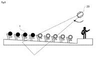
図5は,制御システム2が発光装置1を制御する他の例を,概念的に示したものである。特に,図5では,制御システム2が,指向性信号放射装置23を介して,発光開始命令を各発光装置1に送信する場合の例を示している。図5に示されるように,制御システム2は,指向性信号放射装置23から送信される赤外線や超音波などの指向性信号に発光開始命令を乗せて,イベント会場に存在する複数の発光装置1の一部に対して送信する。指向性信号を検知した発光装置1は,発光開始命令に従い,発光部13の発光を開始する。例えば,発光装置1のメモリ12に記憶されている発光データは,発光開始命令を受信している間だけ,所定の発光パター円で発光を行うという条件が記述されたデータであってもよい。この場合,各発光装置1は,指向性信号(発光開始命令)を検知している間だけ,所定の発光パターンで発光し,指向性信号(発光開始命令)の検知が途切れたときに,発光を停止するようになる。このようにすれば,イベント会場に存在する複数の発光装置1のうちの一部だけを発光させるような,斬新な照明演出を行うことが可能になる。
FIG. 5 conceptually shows another example in which the
図6は,制御システム2が発光装置1を制御するさらに別の例を,概念的に示したものである。特に,図6では,制御システム2が,指向性信号放射装置23を介して,発光開始命令を各発光装置1に送信する場合の例を示している。図6では,イベント会場のステージから近い順に,発光装置1に対して,指向性信号としての発光開始命令が送信されている。また,指向性信号を検知した発光装置1は,指向性信号の検知が途切れても,発光を継続する。このようにすれば,発光装置1の発光が徐々に拡がるような照明演出を実行することができる。
FIG. 6 conceptually shows still another example in which the
(2−2.サブフロ−)
続いて,図7〜図9を参照して,発光装置1の位置登録処理(ステップS1)について,さらに具体的に説明を行う。図7は,位置登録処理(ステップS1)における具体的な処理(サブフロー)を示したフロー図である。図7では,ライブやコンサートのようなイベントにおいて,イベント会場の入場口で,参加者の入場チケットを確認しながら,各参加者に対して発光装置1を貸与する形態のイベントを想定している。また,図8は,イベント会場の入場口において行われる発光装置1の位置登録処理を,概念的に示している。
(2-2. Subflow)
Subsequently, the position registration process (step S1) of the
図7に示されるように,まず,参加者に対してチケットを販売する(ステップS1−1)。チケットは,物理的なチケット(紙製やプラスチック製)であってもよいし,電子チケットであってもよい。図8に示されるように,例えば,チケットには,イベント会場における座席位置の情報(座席番号)が記載されていることが好ましい。また,チケットには,座席位置の情報をコード化したQRコード(登録商標)やバーコードが印刷されていることが好ましい。 As shown in FIG. 7, first, a ticket is sold to the participant (step S1-1). The ticket may be a physical ticket (made of paper or plastic) or an electronic ticket. As shown in FIG. 8, for example, it is preferable that information on a seat position (seat number) in the event venue is described in the ticket. The ticket is preferably printed with a QR code (registered trademark) or bar code obtained by encoding seat position information.
他方,図7に示されるように,参加者に配布される発光装置1のそれぞれについて,識別情報(ID)を付与する作業が行われる(ステップS1−2)。識別情報は,各発光装置1のメモリ12の記憶領域に記憶すればよい。識別情報は,パーソナルコンピュータ(PC)と発光装置1を有線で接続して,発光装置1のメモリ12に書き込むこととしてもよい。また,識別情報は,PCと発光装置1の間で近接的又は遠隔的な無線通信を行うことで,発光装置1のメモリ12に書き込むこととしてもよい。また,図8に示されるように,発光装置1の筐体の外壁には,その発光装置1の識別情報をコード化したQRコード(登録商標)やバーコードが印刷されていることが好ましい。ただし,発光装置1の筐体に識別情報のコードを印刷しなくても,発光装置1のメモリ12から,その発光装置1の識別情報を近接通信で読み取ることができるようにすることもできる。
ステップS1−1及びステップS1−2で説明した作業は,イベントの開催前,又は少なくとも参加者の入場開始前に行われる作業である。
On the other hand, as shown in FIG. 7, an operation of assigning identification information (ID) is performed for each of the
The work described in step S1-1 and step S1-2 is a work performed before the event is held, or at least before the start of entry of the participants.
続いて,イベント会場の入場口での作業について説明する。図7に示されるように,イベント会場の入場口では,参加者が保持するチケットから,その参加者の座席位置に関する情報を読み取る作業が行われる(ステップS1−3)。ここでは,例えば,図8に示されるように,イベント会場の係員が,制御システム2に有線又は無線で接続された読取装置25を利用して,参加者が持つチケットのコードを読み取ることで,制御システム2に,その参加者の座席位置の情報を入力する。ただし,チケットにコードが印刷されていない場合には,イベント会場の係員は,読取装置25に,チケットの座席番号を手入力することとしてもよい。
Next, work at the entrance to the event venue will be explained. As shown in FIG. 7, at the entrance of the event venue, an operation for reading information on the seat position of the participant from the ticket held by the participant is performed (step S1-3). Here, for example, as shown in FIG. 8, an attendant at the event site reads the ticket code held by the participant using a
また,イベント会場の入場口では,参加者のチケットの座席位置の情報を読み取ると共に,その参加者に貸与する発光装置1の識別情報を読み取る作業が行われる(ステップS1−4)。例えば,図8に示されるように,イベント会場の係員が,制御システム2に有線又は無線で接続された読取装置25を利用して,参加者に貸与する発光装置1のコードを読み取ることで,制御システム2に,その参加者に貸与する発光装置1の識別情報を入力する。また,発光装置1にコードが印刷されていない場合であっても,読取装置25によって,発光装置1のメモリ12に記憶された識別情報を,近接通信で読み取ることができるようにしてもよい。さらに,イベント会場の係員は,読取装置25に,発光装置1の識別情報を手入力することとしてもよい。
In addition, at the entrance of the event venue, an operation of reading the seat position information of the participant's ticket and reading the identification information of the
その後,制御システム2は,読取装置25によって読み取られた参加者の座席位置の情報と,その参加者に貸与した発光装置1の識別情報を,互いに関連付けて,位置情報記憶手段24に登録する(ステップS1−5)。例えば,図8には,位置情報記憶手段24に記憶されるデータの構成例が示されている。図8に示されるように,座席位置に関連付けて,発光装置1の識別情報が記憶されている。これにより,制御システム2は,どの発光装置1が,イベント開催期間中に,どの座席位置に所在するかという情報を把握することができる。また,仮に,発光装置1が,参加者自身が購入して持参したものと,参加者に貸与したものがあるような場合,ステップS1−5において,発光装置1の識別情報とチケットの席番号を関連付けて登録する際に,参加者が持参した発光装置1の数と参加者に貸与した発光装置1の数の割合いを把握することが可能になる。
Thereafter, the
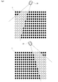
上記のようにして,イベント会場の入場口において発光装置1を参加者に貸与する際に,その発光装置1の位置情報を把握するようにすることで,複数の発光装置1による発光を適切に制御して,図柄や文字を表現するような複雑な照明演出が可能となる。例えば,図9には,複数の発光装置1による発光を利用して,図柄を表現した照明演出の例が示されている。このように,複数の発光装置1の一つ一つについて,イベント開催期間中における所在位置を把握しておくことで,イベント会場全体を統一して,複雑な照明演出が可能となる。
As described above, when the
以上,本願明細書では,本発明の内容を表現するために,図面を参照しながら本発明の実施形態の説明を行った。ただし,本発明は,上記実施形態に限定されるものではなく,本願明細書に記載された事項に基づいて当業者が自明な変更形態や改良形態を包含するものである。 As mentioned above, in this specification, in order to express the content of this invention, embodiment of this invention was described, referring drawings. However, the present invention is not limited to the above-described embodiments, but includes modifications and improvements obvious to those skilled in the art based on the matters described in the present specification.
本発明は,複数の発光装置の発光状態を制御することにより行われる照明演出方法と,この方法を実現するための照明演出システムに関する。従って,本発明は,ライブや,コンサート,舞台のようなイベントの興行産業において好適に利用し得る。 The present invention relates to an illumination effect method performed by controlling light emission states of a plurality of light emitting devices, and an illumination effect system for realizing the method. Therefore, the present invention can be suitably used in the entertainment industry for events such as live performances, concerts, and stage performances.
1…発光装置 2…制御システム
10…制御部(発光装置) 11…データ受信部 12…メモリ
13…発光部 14…指向性信号検出部 15…発光制御部
16…バッテリ 17…スイッチ
20…制御手段(制御システム) 21…発光データ記憶手段 22…データ送信装置
23…指向性信号放射装置 24…位置情報記憶手段 25…読取装置
26…発光データ作成手段
100…照明演出システム
DESCRIPTION OF
Claims (6)
前記制御システム(2)が,発光データ記憶手段(21)から発光データを読み出し,データ送信装置(22)によって,前記複数の発光装置(1)のそれぞれに対して,当該発光データを送信する工程と,
前記複数の発光装置(1)が,データ受信部(11)によって,前記制御システム(2)から送信された前記発光データを受信する工程と,
前記複数の発光装置(1)が,前記データ受信部(11)によって受信した前記発光データを,メモリ(12)に記憶する工程と,
前記制御システム(2)が,前記複数の発光装置(1)のそれぞれに対し,発光開始命令を送信する工程と,
前記複数の発光装置(1)が,前記制御システム(2)から送信された前記発光開始命令を受信する工程と,
前記複数の発光装置(2)が,前記発光開始命令を受信した後に,前記メモリ(12)から前記発光データを読み出し,当該発光データに基づいて,発光部(13)を発光させる工程と,を含む
照明演出方法。 A lighting production method executed by a plurality of light emitting devices (1) and a control system (2),
The control system (2) reads the light emission data from the light emission data storage means (21), and transmits the light emission data to each of the plurality of light emitting devices (1) by the data transmission device (22). When,
The plurality of light emitting devices (1) receiving the light emission data transmitted from the control system (2) by the data receiving unit (11);
The plurality of light emitting devices (1) storing the light emission data received by the data receiving unit (11) in a memory (12);
The control system (2) transmitting a light emission start command to each of the plurality of light emitting devices (1);
The plurality of light emitting devices (1) receiving the light emission start command transmitted from the control system (2);
The plurality of light emitting devices (2), after receiving the light emission start command, reading the light emission data from the memory (12) and causing the light emitting unit (13) to emit light based on the light emission data. Including lighting production method.
請求項1に記載の照明演出方法。 The illumination according to claim 1, wherein the light emission data and the light emission start command are transmitted from the control system (2) to each of the plurality of light emitting devices (1) within an event period. Direction method.
前記発光開始命令を受信する工程において,前記複数の発光装置(1)の少なくとも一部は,指向性信号検出部(14)により,前記指向性信号として送信された前記発光開始命令を受信する
請求項1又は請求項2に記載の照明演出方法。 In the step of transmitting the light emission start command, the control system (2) transmits the light emission start command as a directional signal by the directional signal emitting device (23).
In the step of receiving the light emission start command, at least a part of the plurality of light emitting devices (1) receives the light emission start command transmitted as the directional signal by the directional signal detection unit (14). Item 3. The lighting effect method according to item 1 or 2.
前記発光データ記憶手段(21)には,前記発光装置(1)の配置される位置に応じて異なる複数の発光データが記憶されており,
前記発光データを送信する工程において,前記制御システム(2)は,前記位置データ記憶手段(24)に登録されている前記位置情報と前記識別情報に基づいて,前記複数の発光装置(1)ごとに,前記発光データ記憶手段(21)から読み出して送信する発光データを決定する
請求項1から請求項3のいずれかに記載の照明演出方法。 The control system (2) registers the position information regarding the position where each of the plurality of light emitting devices (1) is arranged in the position data storage means (24) in association with the identification information of the light emitting device (1). Including a location registration process to
The light emission data storage means (21) stores a plurality of different light emission data depending on the position where the light emitting device (1) is arranged,
In the step of transmitting the light emission data, the control system (2), for each of the plurality of light emitting devices (1), based on the position information and the identification information registered in the position data storage means (24). The lighting effect method according to any one of claims 1 to 3, further comprising: determining light emission data to be read and transmitted from the light emission data storage means (21).
前記制御システム(2)が,読取装置(25)によって,イベントの開催前に,イベントの参加者に配布されたチケットに付与されている位置情報と,当該イベントの参加者に配布された前記発光装置(1)に付与されている識別情報を,読み取る工程と,
前記制御システム(2)が,前記読取装置(25)によって読み取った前記位置情報と前記識別情報を関連付けて,前記位置データ記憶手段(24)に登録する工程と,を含む
請求項4に記載の照明演出方法。 The location registration step includes:
The control system (2), by the reading device (25), before the event is held, the location information given to the ticket distributed to the event participant and the light emission distributed to the event participant. Reading the identification information given to the device (1);
The control system (2) includes the step of associating the position information read by the reading device (25) with the identification information and registering it in the position data storage means (24). Lighting production method.
前記制御システム(2)は,
発光データ記憶手段(21)から読み出した発光データを,前記複数の発光装置(1)のそれぞれに対して送信するデータ送信装置(22)と,
前記発光データの送信が完了した後に,前記複数の発光装置(1)のそれぞれに対し,発光開始命令を送信する手段と,を有し,
前記発光装置(1)のそれぞれは,
前記制御システム(2)から送信された前記発光データを受信するデータ受信部(11)と,
前記データ受信部(11)によって受信した前記発光データを記憶するメモリ(12)と,
前記制御システム(2)から送信された前記発光開始命令を受信する手段と,
前記発光開始命令を受信した後に,前記メモリ(12)に記憶されている前記発光データに基づいて発光する発光部(13)と,を有する
照明演出システム。 There is an illumination production system comprising a plurality of light emitting devices (1) and a control system (2),
The control system (2)
A data transmission device (22) for transmitting the light emission data read from the light emission data storage means (21) to each of the plurality of light emitting devices (1);
Means for transmitting a light emission start command to each of the plurality of light emitting devices (1) after the transmission of the light emission data is completed,
Each of the light emitting devices (1)
A data receiver (11) for receiving the light emission data transmitted from the control system (2);
A memory (12) for storing the light emission data received by the data receiving unit (11);
Means for receiving the light emission start command transmitted from the control system (2);
A lighting production system comprising: a light emitting unit (13) that emits light based on the light emission data stored in the memory (12) after receiving the light emission start command.
Priority Applications (2)
| Application Number | Priority Date | Filing Date | Title |
|---|---|---|---|
| JP2013139333A JP6276524B2 (en) | 2013-07-02 | 2013-07-02 | Illumination production method and illumination production system |
| PCT/JP2014/067364 WO2015002137A1 (en) | 2013-07-02 | 2014-06-30 | Stage lighting method and stage lighting system |
Applications Claiming Priority (1)
| Application Number | Priority Date | Filing Date | Title |
|---|---|---|---|
| JP2013139333A JP6276524B2 (en) | 2013-07-02 | 2013-07-02 | Illumination production method and illumination production system |
Publications (2)
| Publication Number | Publication Date |
|---|---|
| JP2015011981A true JP2015011981A (en) | 2015-01-19 |
| JP6276524B2 JP6276524B2 (en) | 2018-02-07 |
Family
ID=52143712
Family Applications (1)
| Application Number | Title | Priority Date | Filing Date |
|---|---|---|---|
| JP2013139333A Active JP6276524B2 (en) | 2013-07-02 | 2013-07-02 | Illumination production method and illumination production system |
Country Status (2)
| Country | Link |
|---|---|
| JP (1) | JP6276524B2 (en) |
| WO (1) | WO2015002137A1 (en) |
Cited By (38)
| Publication number | Priority date | Publication date | Assignee | Title |
|---|---|---|---|---|
| JP2015073182A (en) * | 2013-10-02 | 2015-04-16 | 株式会社電通 | Content synchronization system, event direction system, synchronization device and recording medium |
| WO2016125849A1 (en) * | 2015-02-06 | 2016-08-11 | 株式会社ルイファン・ジャパン | Illuminant aggregation device and illuminant aggregation method |
| JP2017005420A (en) * | 2015-06-08 | 2017-01-05 | 株式会社東芝 | Network construction system |
| JP2017049789A (en) * | 2015-09-01 | 2017-03-09 | エヌ・ティ・ティ・ソフトウェア株式会社 | Display control apparatus, control method, and control program |
| JP2017091840A (en) * | 2015-11-11 | 2017-05-25 | 株式会社ルイファン・ジャパン | Lamp fitting system and lamp fitting |
| CN107135567A (en) * | 2016-02-29 | 2017-09-05 | 哈纳姆阿泰克株式会社 | Luminescent control system |
| JP2017156190A (en) * | 2016-03-01 | 2017-09-07 | mplusplus株式会社 | Communication control system |
| JP2017169692A (en) * | 2016-03-22 | 2017-09-28 | 株式会社東芝 | Event article and event performance method |
| JP2017199637A (en) * | 2016-04-28 | 2017-11-02 | 株式会社ラパンクリエイト | System having plural light emitting terminals |
| KR101811622B1 (en) * | 2016-03-11 | 2017-12-26 | 주식회사 팬라이트 | Emission control system using modulation of spreading century |
| KR101811620B1 (en) * | 2016-02-29 | 2017-12-26 | 주식회사 팬라이트 | Emission control system using barcode information |
| KR20170142156A (en) * | 2016-03-11 | 2017-12-27 | 주식회사 팬라이트 | Emission control system using modulation of spreading century |
| JP2018022635A (en) * | 2016-08-04 | 2018-02-08 | アイリスオーヤマ株式会社 | Lighting device and lighting system |
| KR20180015704A (en) * | 2018-02-02 | 2018-02-13 | 주식회사 팬라이트 | Master system and method for performance direction |
| KR20180015702A (en) * | 2018-02-02 | 2018-02-13 | 주식회사 팬라이트 | Performance directing system |
| KR20180015703A (en) * | 2018-02-02 | 2018-02-13 | 주식회사 팬라이트 | Master system and method for performance direction |
| KR101900326B1 (en) * | 2017-12-18 | 2018-09-19 | 주식회사 팬라이트 | Performance directing system |
| JP2018159680A (en) * | 2017-03-24 | 2018-10-11 | Sus株式会社 | Illumination device for visual inspection |
| WO2018199195A1 (en) | 2017-04-27 | 2018-11-01 | 小▲柳▼富 | Event staging system and event staging program |
| JP2019021580A (en) * | 2017-07-20 | 2019-02-07 | 中村展設株式会社 | Portable light-emitting device, light-emitting system, and control method of portable light-emitting device |
| KR20190013111A (en) * | 2017-07-31 | 2019-02-11 | 엘지전자 주식회사 | Lighting device based scenario activation using push service, push server, controlling device and communication device controlling the lighting device |
| KR20190016530A (en) * | 2018-02-02 | 2019-02-18 | 주식회사 팬라이트 | Performance directing system |
| KR20190017845A (en) * | 2019-02-08 | 2019-02-20 | 주식회사 팬라이트 | Performance directing system |
| JP6473544B1 (en) * | 2018-09-19 | 2019-02-20 | 日本電業工作株式会社 | Rendering method, receiving apparatus and communication system |
| JP6473545B1 (en) * | 2018-09-19 | 2019-02-20 | 日本電業工作株式会社 | Transmission system, transmission device and production system |
| KR20190070220A (en) * | 2017-12-12 | 2019-06-20 | 엘지전자 주식회사 | Lighting device and performance system including lighting device |
| WO2019117396A1 (en) * | 2017-12-12 | 2019-06-20 | 엘지전자 주식회사 | Lighting device and performance system comprising same |
| JP2020098802A (en) * | 2015-06-18 | 2020-06-25 | ファンライト シーオー., エルティーディー.Fanlight Co., Ltd. | Wireless illumination control system |
| WO2020218666A1 (en) * | 2019-04-22 | 2020-10-29 | 주식회사 비트로 | Method and apparatus for controlling multiple wireless lighting devices |
| WO2020262857A1 (en) * | 2019-06-24 | 2020-12-30 | 최지선 | Performance directing system |
| WO2020262856A1 (en) * | 2019-06-24 | 2020-12-30 | 최지선 | Performance directing system |
| JP2021508147A (en) * | 2017-12-12 | 2021-02-25 | ビッグヒット エンターテインメント カンパニー リミテッド | Central server and dramatic entertainment system including it |
| US11096263B2 (en) | 2019-04-22 | 2021-08-17 | Beatro Co., Ltd. | Method and device for controlling a plurality of wireless lighting devices |
| KR20210102174A (en) * | 2020-06-08 | 2021-08-19 | 이지현 | Performance directing system |
| WO2021210938A1 (en) * | 2020-04-17 | 2021-10-21 | 최지선 | Remote directing system and remote directing method |
| WO2022173074A1 (en) * | 2021-02-10 | 2022-08-18 | 주식회사 팬라이트 | System, apparatus, and method for controlling bitmap for performance scene production |
| WO2023276885A1 (en) * | 2021-07-02 | 2023-01-05 | パナソニックIpマネジメント株式会社 | Illumination system and illumination control method |
| US11974381B2 (en) | 2019-06-24 | 2024-04-30 | Ji Sun Choi | System and method for directing performance |
Families Citing this family (3)
| Publication number | Priority date | Publication date | Assignee | Title |
|---|---|---|---|---|
| JP6532013B2 (en) * | 2015-04-06 | 2019-06-19 | 国立研究開発法人産業技術総合研究所 | Event light emitting device and information processing system using the device |
| JP6726118B2 (en) * | 2017-02-22 | 2020-07-22 | パナソニック インテレクチュアル プロパティ コーポレーション オブ アメリカPanasonic Intellectual Property Corporation of America | Control device, wireless communication terminal, and position estimation system |
| EP3852501A1 (en) * | 2020-01-20 | 2021-07-21 | Arman Emami | Method for outputting synchronized light signals |
Citations (5)
| Publication number | Priority date | Publication date | Assignee | Title |
|---|---|---|---|---|
| JP2000195681A (en) * | 1998-12-28 | 2000-07-14 | Toshiba Lighting & Technology Corp | Dimmer control system, radio transmitting unit and radio dimming device |
| JP2005251443A (en) * | 2004-03-02 | 2005-09-15 | Japan Radio Co Ltd | Light emission control system |
| JP2006276127A (en) * | 2005-03-28 | 2006-10-12 | Osaki Electric Co Ltd | Large-scale graphic display system, graphic display master controller, and graphic display slave controller |
| JP2009070832A (en) * | 2001-06-13 | 2009-04-02 | Philips Solid-State Lighting Solutions Inc | System and method for controlling light system |
| JP2013004323A (en) * | 2011-06-16 | 2013-01-07 | Namco Bandai Games Inc | Terminal device and event directing system |
Family Cites Families (1)
| Publication number | Priority date | Publication date | Assignee | Title |
|---|---|---|---|---|
| JP2007115412A (en) * | 2005-10-18 | 2007-05-10 | Totoku Electric Co Ltd | Presentation method, presentation system, and portable light emitting device |
-
2013
- 2013-07-02 JP JP2013139333A patent/JP6276524B2/en active Active
-
2014
- 2014-06-30 WO PCT/JP2014/067364 patent/WO2015002137A1/en active Application Filing
Patent Citations (5)
| Publication number | Priority date | Publication date | Assignee | Title |
|---|---|---|---|---|
| JP2000195681A (en) * | 1998-12-28 | 2000-07-14 | Toshiba Lighting & Technology Corp | Dimmer control system, radio transmitting unit and radio dimming device |
| JP2009070832A (en) * | 2001-06-13 | 2009-04-02 | Philips Solid-State Lighting Solutions Inc | System and method for controlling light system |
| JP2005251443A (en) * | 2004-03-02 | 2005-09-15 | Japan Radio Co Ltd | Light emission control system |
| JP2006276127A (en) * | 2005-03-28 | 2006-10-12 | Osaki Electric Co Ltd | Large-scale graphic display system, graphic display master controller, and graphic display slave controller |
| JP2013004323A (en) * | 2011-06-16 | 2013-01-07 | Namco Bandai Games Inc | Terminal device and event directing system |
Cited By (76)
| Publication number | Priority date | Publication date | Assignee | Title |
|---|---|---|---|---|
| JP2015073182A (en) * | 2013-10-02 | 2015-04-16 | 株式会社電通 | Content synchronization system, event direction system, synchronization device and recording medium |
| WO2016125849A1 (en) * | 2015-02-06 | 2016-08-11 | 株式会社ルイファン・ジャパン | Illuminant aggregation device and illuminant aggregation method |
| JP2016146069A (en) * | 2015-02-06 | 2016-08-12 | 株式会社ルイファン・ジャパン | Luminous body tabulation device and luminous body tabulation method |
| JP2017005420A (en) * | 2015-06-08 | 2017-01-05 | 株式会社東芝 | Network construction system |
| US11629823B2 (en) | 2015-06-18 | 2023-04-18 | Fanlight Co., Ltd. | Wireless lighting control system |
| US11867362B2 (en) | 2015-06-18 | 2024-01-09 | Fanlight Co., Ltd. | Wireless lighting control system |
| JP2021052013A (en) * | 2015-06-18 | 2021-04-01 | ファンライト シーオー., エルティーディー.Fanlight Co., Ltd. | Wireless illumination control system |
| JP2020098802A (en) * | 2015-06-18 | 2020-06-25 | ファンライト シーオー., エルティーディー.Fanlight Co., Ltd. | Wireless illumination control system |
| JP2017049789A (en) * | 2015-09-01 | 2017-03-09 | エヌ・ティ・ティ・ソフトウェア株式会社 | Display control apparatus, control method, and control program |
| JP2017091840A (en) * | 2015-11-11 | 2017-05-25 | 株式会社ルイファン・ジャパン | Lamp fitting system and lamp fitting |
| US11638137B2 (en) | 2016-02-29 | 2023-04-25 | Hanam Artec Co., Ltd. | Lighting control system using barcode information |
| JP2017157549A (en) * | 2016-02-29 | 2017-09-07 | ハナムアーテック シーオー., エルティーディーHanam Artec Co., Ltd | Master device and slave device constituting emission control system |
| KR101811620B1 (en) * | 2016-02-29 | 2017-12-26 | 주식회사 팬라이트 | Emission control system using barcode information |
| US11350258B2 (en) | 2016-02-29 | 2022-05-31 | Hanam Artec Co., Ltd. | Lighting control system using barcode information |
| US10509930B2 (en) | 2016-02-29 | 2019-12-17 | Hanam Artec Co., Ltd. | Lighting control system using barcode information |
| US11924729B2 (en) | 2016-02-29 | 2024-03-05 | Hanam Artec Co., Ltd. | Lighting control system using barcode information |
| US10387700B2 (en) | 2016-02-29 | 2019-08-20 | Hanam Artec Co., Ltd. | Emission control system using barcode information |
| CN107135567B (en) * | 2016-02-29 | 2020-05-05 | 哈纳姆阿泰克株式会社 | Light emission control system |
| EP3364388A1 (en) * | 2016-02-29 | 2018-08-22 | Hanam Artec Co., Ltd. | Emission control system using barcode information |
| EP3713379A1 (en) * | 2016-02-29 | 2020-09-23 | Hanam Artec Co., Ltd. | Emission control system using barcode information |
| CN107135567A (en) * | 2016-02-29 | 2017-09-05 | 哈纳姆阿泰克株式会社 | Luminescent control system |
| US10762315B2 (en) | 2016-02-29 | 2020-09-01 | Hanam Artec Co., Ltd. | Lighting control system using barcode information |
| JP2017156190A (en) * | 2016-03-01 | 2017-09-07 | mplusplus株式会社 | Communication control system |
| KR102327111B1 (en) * | 2016-03-11 | 2021-11-16 | 주식회사 팬라이트 | Emission control system using modulation of spreading century |
| KR101811622B1 (en) * | 2016-03-11 | 2017-12-26 | 주식회사 팬라이트 | Emission control system using modulation of spreading century |
| KR20170142156A (en) * | 2016-03-11 | 2017-12-27 | 주식회사 팬라이트 | Emission control system using modulation of spreading century |
| JP2017169692A (en) * | 2016-03-22 | 2017-09-28 | 株式会社東芝 | Event article and event performance method |
| JP2017199637A (en) * | 2016-04-28 | 2017-11-02 | 株式会社ラパンクリエイト | System having plural light emitting terminals |
| JP7100916B2 (en) | 2016-08-04 | 2022-07-14 | アイリスオーヤマ株式会社 | Lighting system |
| JP2021114475A (en) * | 2016-08-04 | 2021-08-05 | アイリスオーヤマ株式会社 | Illumination system |
| JP2018022635A (en) * | 2016-08-04 | 2018-02-08 | アイリスオーヤマ株式会社 | Lighting device and lighting system |
| JP2018159680A (en) * | 2017-03-24 | 2018-10-11 | Sus株式会社 | Illumination device for visual inspection |
| US11470708B2 (en) | 2017-04-27 | 2022-10-11 | Tom KOYANAGI | Event staging system and event staging program |
| WO2018199195A1 (en) | 2017-04-27 | 2018-11-01 | 小▲柳▼富 | Event staging system and event staging program |
| JP2019021580A (en) * | 2017-07-20 | 2019-02-07 | 中村展設株式会社 | Portable light-emitting device, light-emitting system, and control method of portable light-emitting device |
| KR102403230B1 (en) * | 2017-07-31 | 2022-05-27 | 주식회사 하이브 | Lighting device based scenario activation using push service, push server, controlling device and communication device controlling the lighting device |
| KR20190013111A (en) * | 2017-07-31 | 2019-02-11 | 엘지전자 주식회사 | Lighting device based scenario activation using push service, push server, controlling device and communication device controlling the lighting device |
| KR102008267B1 (en) * | 2017-12-12 | 2019-08-07 | 엘지전자 주식회사 | Lighting device and performance system including lighting device |
| WO2019117396A1 (en) * | 2017-12-12 | 2019-06-20 | 엘지전자 주식회사 | Lighting device and performance system comprising same |
| KR20190070220A (en) * | 2017-12-12 | 2019-06-20 | 엘지전자 주식회사 | Lighting device and performance system including lighting device |
| JP7018508B2 (en) | 2017-12-12 | 2022-02-10 | ハイブ カンパニー リミテッド | Central server and dramatic entertainment system including it |
| JP2021508147A (en) * | 2017-12-12 | 2021-02-25 | ビッグヒット エンターテインメント カンパニー リミテッド | Central server and dramatic entertainment system including it |
| US11350509B2 (en) | 2017-12-12 | 2022-05-31 | Hybe Co., Ltd | Lighting device and performance system comprising same |
| US11678423B2 (en) | 2017-12-12 | 2023-06-13 | Hybe Co., Ltd | Central server and dramatic performance system including same |
| KR20210136958A (en) * | 2017-12-18 | 2021-11-17 | 주식회사 팬라이트 | Emission control system using modulation of spreading century |
| KR101900326B1 (en) * | 2017-12-18 | 2018-09-19 | 주식회사 팬라이트 | Performance directing system |
| KR102376722B1 (en) * | 2017-12-18 | 2022-03-21 | 주식회사 팬라이트 | Emission control system using modulation of spreading century |
| KR101981469B1 (en) * | 2018-02-02 | 2019-05-23 | 주식회사 팬라이트 | Master system and method for performance direction |
| KR102074976B1 (en) * | 2018-02-02 | 2020-02-07 | 주식회사 팬라이트 | Performance directing system |
| KR101979350B1 (en) * | 2018-02-02 | 2019-05-16 | 주식회사 팬라이트 | Performance directing system |
| KR101979345B1 (en) * | 2018-02-02 | 2019-05-16 | 주식회사 팬라이트 | Master system and method for performance direction |
| KR20180015704A (en) * | 2018-02-02 | 2018-02-13 | 주식회사 팬라이트 | Master system and method for performance direction |
| KR20180015702A (en) * | 2018-02-02 | 2018-02-13 | 주식회사 팬라이트 | Performance directing system |
| KR20190016530A (en) * | 2018-02-02 | 2019-02-18 | 주식회사 팬라이트 | Performance directing system |
| KR20180015703A (en) * | 2018-02-02 | 2018-02-13 | 주식회사 팬라이트 | Master system and method for performance direction |
| WO2020059088A1 (en) * | 2018-09-19 | 2020-03-26 | 日本電業工作株式会社 | Directing method, receiving device, light-emitting device and communication system |
| JP6473544B1 (en) * | 2018-09-19 | 2019-02-20 | 日本電業工作株式会社 | Rendering method, receiving apparatus and communication system |
| JP6473545B1 (en) * | 2018-09-19 | 2019-02-20 | 日本電業工作株式会社 | Transmission system, transmission device and production system |
| JP2020047475A (en) * | 2018-09-19 | 2020-03-26 | 日本電業工作株式会社 | Transmission system, transmitter, and rendering system |
| WO2020059089A1 (en) * | 2018-09-19 | 2020-03-26 | 日本電業工作株式会社 | Transmission system, transmission device and directing system |
| JP2020047474A (en) * | 2018-09-19 | 2020-03-26 | 日本電業工作株式会社 | Rendering method, receiver, and communication system |
| KR20190017845A (en) * | 2019-02-08 | 2019-02-20 | 주식회사 팬라이트 | Performance directing system |
| KR102093280B1 (en) * | 2019-02-08 | 2020-03-25 | 주식회사 팬라이트 | Performance directing system |
| WO2020218666A1 (en) * | 2019-04-22 | 2020-10-29 | 주식회사 비트로 | Method and apparatus for controlling multiple wireless lighting devices |
| US11096263B2 (en) | 2019-04-22 | 2021-08-17 | Beatro Co., Ltd. | Method and device for controlling a plurality of wireless lighting devices |
| WO2020262856A1 (en) * | 2019-06-24 | 2020-12-30 | 최지선 | Performance directing system |
| US11974381B2 (en) | 2019-06-24 | 2024-04-30 | Ji Sun Choi | System and method for directing performance |
| WO2020262857A1 (en) * | 2019-06-24 | 2020-12-30 | 최지선 | Performance directing system |
| WO2021210938A1 (en) * | 2020-04-17 | 2021-10-21 | 최지선 | Remote directing system and remote directing method |
| US11930579B2 (en) | 2020-04-21 | 2024-03-12 | Ji Sun Choi | System and method for directing performance |
| KR20210102174A (en) * | 2020-06-08 | 2021-08-19 | 이지현 | Performance directing system |
| KR102536535B1 (en) * | 2020-06-08 | 2023-05-26 | 이지현 | Performance directing system |
| KR102410046B1 (en) * | 2020-06-08 | 2022-06-15 | 이지현 | Performance directing system |
| KR20220084004A (en) * | 2020-06-08 | 2022-06-21 | 이지현 | Performance directing system |
| WO2022173074A1 (en) * | 2021-02-10 | 2022-08-18 | 주식회사 팬라이트 | System, apparatus, and method for controlling bitmap for performance scene production |
| WO2023276885A1 (en) * | 2021-07-02 | 2023-01-05 | パナソニックIpマネジメント株式会社 | Illumination system and illumination control method |
Also Published As
| Publication number | Publication date |
|---|---|
| WO2015002137A1 (en) | 2015-01-08 |
| JP6276524B2 (en) | 2018-02-07 |
Similar Documents
| Publication | Publication Date | Title |
|---|---|---|
| JP6276524B2 (en) | Illumination production method and illumination production system | |
| KR101979345B1 (en) | Master system and method for performance direction | |
| US10762315B2 (en) | Lighting control system using barcode information | |
| CN106105104A (en) | For sharing between illuminator and/or the system of attribute of synchronized transmissions light | |
| KR101979350B1 (en) | Performance directing system | |
| CN106165539A (en) | Radio controllable portable illuminator | |
| KR101981469B1 (en) | Master system and method for performance direction | |
| KR102074976B1 (en) | Performance directing system | |
| KR20200068637A (en) | Performance directing system | |
| JP6751605B2 (en) | Lighting control system | |
| JP6186347B2 (en) | Lighting device light emission control system, lighting device light emission control method, and program | |
| KR101900326B1 (en) | Performance directing system | |
| JP7421644B2 (en) | Performance production system, device and method using multiple layers | |
| JP2018206516A (en) | Apparatus registration method, program for executing the same, and apparatus system | |
| CN108347803B (en) | Interactive luminous effect device and method for configuring luminous effect pattern | |
| JP6307535B2 (en) | State identification system and state identification method | |
| KR102093280B1 (en) | Performance directing system | |
| KR101811620B1 (en) | Emission control system using barcode information | |
| KR102410046B1 (en) | Performance directing system | |
| KR20200032078A (en) | Performance directing system | |
| KR20240018535A (en) | Light emitting apparatus and method for operating the same | |
| JP2024006980A (en) | Seat-library pairing method and system using short-distance wireless communication | |
| TW201525956A (en) | Method and system for patterning elements having two states |
Legal Events
| Date | Code | Title | Description |
|---|---|---|---|
| A621 | Written request for application examination |
Free format text: JAPANESE INTERMEDIATE CODE: A621 Effective date: 20160607 |
|
| A131 | Notification of reasons for refusal |
Free format text: JAPANESE INTERMEDIATE CODE: A131 Effective date: 20170509 |
|
| A601 | Written request for extension of time |
Free format text: JAPANESE INTERMEDIATE CODE: A601 Effective date: 20170710 |
|
| A521 | Request for written amendment filed |
Free format text: JAPANESE INTERMEDIATE CODE: A523 Effective date: 20170908 |
|
| TRDD | Decision of grant or rejection written | ||
| A01 | Written decision to grant a patent or to grant a registration (utility model) |
Free format text: JAPANESE INTERMEDIATE CODE: A01 Effective date: 20180109 |
|
| A61 | First payment of annual fees (during grant procedure) |
Free format text: JAPANESE INTERMEDIATE CODE: A61 Effective date: 20180112 |
|
| R150 | Certificate of patent or registration of utility model |
Ref document number: 6276524 Country of ref document: JP Free format text: JAPANESE INTERMEDIATE CODE: R150 |
|
| R250 | Receipt of annual fees |
Free format text: JAPANESE INTERMEDIATE CODE: R250 |
|
| R250 | Receipt of annual fees |
Free format text: JAPANESE INTERMEDIATE CODE: R250 |
|
| R250 | Receipt of annual fees |
Free format text: JAPANESE INTERMEDIATE CODE: R250 |
|
| R250 | Receipt of annual fees |
Free format text: JAPANESE INTERMEDIATE CODE: R250 |