JP2015009698A - Vehicular brake system - Google Patents
Vehicular brake system Download PDFInfo
- Publication number
- JP2015009698A JP2015009698A JP2013137322A JP2013137322A JP2015009698A JP 2015009698 A JP2015009698 A JP 2015009698A JP 2013137322 A JP2013137322 A JP 2013137322A JP 2013137322 A JP2013137322 A JP 2013137322A JP 2015009698 A JP2015009698 A JP 2015009698A
- Authority
- JP
- Japan
- Prior art keywords
- piston
- cylinder
- spool
- master
- pressure
- Prior art date
- Legal status (The legal status is an assumption and is not a legal conclusion. Google has not performed a legal analysis and makes no representation as to the accuracy of the status listed.)
- Pending
Links
Images


Classifications
-
- B—PERFORMING OPERATIONS; TRANSPORTING
- B60—VEHICLES IN GENERAL
- B60T—VEHICLE BRAKE CONTROL SYSTEMS OR PARTS THEREOF; BRAKE CONTROL SYSTEMS OR PARTS THEREOF, IN GENERAL; ARRANGEMENT OF BRAKING ELEMENTS ON VEHICLES IN GENERAL; PORTABLE DEVICES FOR PREVENTING UNWANTED MOVEMENT OF VEHICLES; VEHICLE MODIFICATIONS TO FACILITATE COOLING OF BRAKES
- B60T13/00—Transmitting braking action from initiating means to ultimate brake actuator with power assistance or drive; Brake systems incorporating such transmitting means, e.g. air-pressure brake systems
- B60T13/10—Transmitting braking action from initiating means to ultimate brake actuator with power assistance or drive; Brake systems incorporating such transmitting means, e.g. air-pressure brake systems with fluid assistance, drive, or release
- B60T13/12—Transmitting braking action from initiating means to ultimate brake actuator with power assistance or drive; Brake systems incorporating such transmitting means, e.g. air-pressure brake systems with fluid assistance, drive, or release the fluid being liquid
- B60T13/14—Transmitting braking action from initiating means to ultimate brake actuator with power assistance or drive; Brake systems incorporating such transmitting means, e.g. air-pressure brake systems with fluid assistance, drive, or release the fluid being liquid using accumulators or reservoirs fed by pumps
- B60T13/142—Systems with master cylinder
- B60T13/145—Master cylinder integrated or hydraulically coupled with booster
- B60T13/146—Part of the system directly actuated by booster pressure
-
- B—PERFORMING OPERATIONS; TRANSPORTING
- B60—VEHICLES IN GENERAL
- B60T—VEHICLE BRAKE CONTROL SYSTEMS OR PARTS THEREOF; BRAKE CONTROL SYSTEMS OR PARTS THEREOF, IN GENERAL; ARRANGEMENT OF BRAKING ELEMENTS ON VEHICLES IN GENERAL; PORTABLE DEVICES FOR PREVENTING UNWANTED MOVEMENT OF VEHICLES; VEHICLE MODIFICATIONS TO FACILITATE COOLING OF BRAKES
- B60T13/00—Transmitting braking action from initiating means to ultimate brake actuator with power assistance or drive; Brake systems incorporating such transmitting means, e.g. air-pressure brake systems
- B60T13/10—Transmitting braking action from initiating means to ultimate brake actuator with power assistance or drive; Brake systems incorporating such transmitting means, e.g. air-pressure brake systems with fluid assistance, drive, or release
- B60T13/66—Electrical control in fluid-pressure brake systems
- B60T13/662—Electrical control in fluid-pressure brake systems characterised by specified functions of the control system components
-
- B—PERFORMING OPERATIONS; TRANSPORTING
- B60—VEHICLES IN GENERAL
- B60T—VEHICLE BRAKE CONTROL SYSTEMS OR PARTS THEREOF; BRAKE CONTROL SYSTEMS OR PARTS THEREOF, IN GENERAL; ARRANGEMENT OF BRAKING ELEMENTS ON VEHICLES IN GENERAL; PORTABLE DEVICES FOR PREVENTING UNWANTED MOVEMENT OF VEHICLES; VEHICLE MODIFICATIONS TO FACILITATE COOLING OF BRAKES
- B60T13/00—Transmitting braking action from initiating means to ultimate brake actuator with power assistance or drive; Brake systems incorporating such transmitting means, e.g. air-pressure brake systems
- B60T13/10—Transmitting braking action from initiating means to ultimate brake actuator with power assistance or drive; Brake systems incorporating such transmitting means, e.g. air-pressure brake systems with fluid assistance, drive, or release
- B60T13/66—Electrical control in fluid-pressure brake systems
- B60T13/68—Electrical control in fluid-pressure brake systems by electrically-controlled valves
- B60T13/686—Electrical control in fluid-pressure brake systems by electrically-controlled valves in hydraulic systems or parts thereof
-
- B—PERFORMING OPERATIONS; TRANSPORTING
- B60—VEHICLES IN GENERAL
- B60T—VEHICLE BRAKE CONTROL SYSTEMS OR PARTS THEREOF; BRAKE CONTROL SYSTEMS OR PARTS THEREOF, IN GENERAL; ARRANGEMENT OF BRAKING ELEMENTS ON VEHICLES IN GENERAL; PORTABLE DEVICES FOR PREVENTING UNWANTED MOVEMENT OF VEHICLES; VEHICLE MODIFICATIONS TO FACILITATE COOLING OF BRAKES
- B60T7/00—Brake-action initiating means
- B60T7/02—Brake-action initiating means for personal initiation
- B60T7/04—Brake-action initiating means for personal initiation foot actuated
- B60T7/042—Brake-action initiating means for personal initiation foot actuated by electrical means, e.g. using travel or force sensors
-
- B—PERFORMING OPERATIONS; TRANSPORTING
- B60—VEHICLES IN GENERAL
- B60T—VEHICLE BRAKE CONTROL SYSTEMS OR PARTS THEREOF; BRAKE CONTROL SYSTEMS OR PARTS THEREOF, IN GENERAL; ARRANGEMENT OF BRAKING ELEMENTS ON VEHICLES IN GENERAL; PORTABLE DEVICES FOR PREVENTING UNWANTED MOVEMENT OF VEHICLES; VEHICLE MODIFICATIONS TO FACILITATE COOLING OF BRAKES
- B60T8/00—Arrangements for adjusting wheel-braking force to meet varying vehicular or ground-surface conditions, e.g. limiting or varying distribution of braking force
- B60T8/32—Arrangements for adjusting wheel-braking force to meet varying vehicular or ground-surface conditions, e.g. limiting or varying distribution of braking force responsive to a speed condition, e.g. acceleration or deceleration
- B60T8/34—Arrangements for adjusting wheel-braking force to meet varying vehicular or ground-surface conditions, e.g. limiting or varying distribution of braking force responsive to a speed condition, e.g. acceleration or deceleration having a fluid pressure regulator responsive to a speed condition
- B60T8/40—Arrangements for adjusting wheel-braking force to meet varying vehicular or ground-surface conditions, e.g. limiting or varying distribution of braking force responsive to a speed condition, e.g. acceleration or deceleration having a fluid pressure regulator responsive to a speed condition comprising an additional fluid circuit including fluid pressurising means for modifying the pressure of the braking fluid, e.g. including wheel driven pumps for detecting a speed condition, or pumps which are controlled by means independent of the braking system
- B60T8/4072—Systems in which a driver input signal is used as a control signal for the additional fluid circuit which is normally used for braking
- B60T8/4077—Systems in which the booster is used as an auxiliary pressure source
Landscapes
- Engineering & Computer Science (AREA)
- Transportation (AREA)
- Mechanical Engineering (AREA)
- Physics & Mathematics (AREA)
- Fluid Mechanics (AREA)
- Transmission Of Braking Force In Braking Systems (AREA)
- Braking Systems And Boosters (AREA)
- Regulating Braking Force (AREA)
Abstract
Description
本発明は、車両に付与する制動力を制御する車両用制動装置に関する。 The present invention relates to a vehicle braking device that controls a braking force applied to a vehicle.
車両に付与する制動力を制御する車両用制動装置の一例として、例えば特許文献1に挙げられる車両用制動装置が知られている。この車両用制動装置は、通常のブレーキ装置の踏力感を再現するシミュレータ、ブレーキペダルの操作に応じてアキュムレータ圧から摩擦ブレーキ装置に作用させるマスタ圧を発生させるハイドロブースタを有している。
As an example of a vehicle braking device that controls a braking force applied to a vehicle, for example, a vehicle braking device described in
特許文献1に示される車両用制動装置は、ハイドロブースタとシミュレータと別体となっていたため、大型なものとなり、車両への搭載性が悪いという問題があった。
Since the vehicle braking device disclosed in
本発明は、このような事情に鑑みてなされたものであり、車両への搭載性が良い車両用制動装置を提供することを目的とする。 This invention is made | formed in view of such a situation, and it aims at providing the brake device for vehicles with the mountability to a vehicle with good.
上述した課題を解決するためになされた、請求項1に係る発明は、前後方向に柱形状の空間を有するマスタシリンダと、前記マスタシリンダの空間と接続され、ブレーキフルードの液圧を蓄圧するアキュムレータと、前記マスタシリンダの空間と接続され、ブレーキフルードを貯留するリザーバと、前記マスタシリンダの空間内に前後方向摺動可能に設けられ、摩擦ブレーキ装置に供給されるブレーキフルードで満たされるマスタ室を前方において前記マスタシリンダとの間で形成し、サーボ室を後方において前記マスタシリンダとの間で形成するマスタピストンと、前記マスタシリンダの空間内の前記マスタピストンの後方に設けられ、前記サーボ室と前記リザーバが連通する減圧モード、前記サーボ室と前記アキュムレータが連通する増圧モード、前記サーボ室が密閉される保持モードを切り替えるスプール弁と、前記マスタシリンダの後方に設けられ、運転者の操作力が伝達される操作部材と、前記マスタシリンダの空間内の前記スプール弁の後方に前後方向摺動可能に設けられ、前記操作部材と連結されて前記操作部材からの操作力が伝達され、前記操作力によって前記スプール弁を駆動する入力ピストンと、前記入力ピストンの前方において前記マスタシリンダの空間内に設けられ、前記入力ピストンを後方に付勢するシミュレータ部材と、を有する。
The invention according to
このように、入力ピストンを後方に付勢してシミュレータの役割を果たすシミュレータ部材が、ハイドロブースタを構成するマスタシリンダの空間内に設けられているので、ハイドロブースタとシミュレータが一体となり、車両用制動装置の車両への搭載性が良好となる。 As described above, since the simulator member that urges the input piston rearward and serves as a simulator is provided in the space of the master cylinder that constitutes the hydro booster, the hydro booster and the simulator are integrated into the vehicle brake. The mountability of the apparatus on a vehicle is improved.
(ハイブリッド車両)
以下、本発明の実施形態を図面に基づいて説明する。本実施形態の摩擦ブレーキユニットB(車両用制動装置)が搭載されるハイブリッド車両(以下、単に車両と略す)は、図1に示すように、ハイブリッドシステムによって駆動輪例えば左右前輪Wfl、Wfrを駆動させる車両である。車両は、ブレーキECU6、エンジンECU8、ハイブリッドECU9、ハイドロブースタ10、調圧装置53、液圧発生装置60、ブレーキペダル71、ブレーキセンサ72、エンジン501、モータ502、動力分割機構503、動力伝達機構504、インバータ506、バッテリ507を有している。
(Hybrid vehicle)
Hereinafter, embodiments of the present invention will be described with reference to the drawings. As shown in FIG. 1, a hybrid vehicle (hereinafter simply referred to as a vehicle) on which the friction brake unit B (vehicle braking device) of the present embodiment is mounted drives drive wheels such as left and right front wheels Wfl, Wfr. It is a vehicle to let you. The vehicle includes a
エンジン501の駆動力は、動力分割機構503及び動力伝達機構504を介して駆動輪に伝達されるようになっている。モータ502の駆動力は、動力伝達機構504を介して駆動輪に伝達されるようになっている。
The driving force of the
インバータ506は、モータ502及び発電機505と直流電源としてのバッテリ507との間で電圧を変換するものである。エンジンECU8は、ハイブリッドECU9からの指令に基づいてエンジン501の駆動力を調整する。ハイブリッドECU9は、インバータ506を通してモータ502及び発電機505を制御する。ハイブリッドECU9は、バッテリ507が接続されており、バッテリ507の充電状態、充電電流などを監視している。
The
上述した発電機505、インバータ506、及びバッテリ507から回生ブレーキ装置Aが構成されている。回生ブレーキ装置Aは、後述する「実行回生制動力」に基づき、発電機505による回生制動力を、車輪Wfl、Wfrに発生させるものである。図1に示した実施形態では、モータ502と発電機505は別体であるが、モータと発電機が一体となった、モータジェネレータであっても差し支え無い。
The regenerative braking device A is composed of the above-described
各車輪Wfl、Wfr、Wrl、Wrrに隣接する位置には、各車輪Wfl、Wfr、Wrl、Wrrと一体回転するブレーキディスクDRfl、DRfr、DRrl、DRrrと、ブレーキディスクDRfl、DRfr、DRrl、DRrrにブレーキパッド(不図示)を押し付けて摩擦制動力を発生させる摩擦ブレーキ装置Bfl、Bfr、Brl、Brrが設けられている。摩擦ブレーキ装置Bfl、Bfr、Brl、Brrには、後述のハイドロブースタ10(図2示)により生成される「マスタ圧」により、上記ブレーキパッドをブレーキディスクDRfl、DRfr、DRrl、DRrrに押し付けるホイールシリンダWCfl、WCfr、WCrl、WCrrが設けられている。 At positions adjacent to each wheel Wfl, Wfr, Wrl, Wrr, there are brake discs DRfl, DRfr, DRrl, DRrr that rotate integrally with each wheel Wfl, Wfr, Wrl, Wrr, and brake discs DRfl, DRfr, DRrl, DRrr. Friction brake devices Bfl, Bfr, Brl, and Brr that press a brake pad (not shown) to generate a friction braking force are provided. The friction brake devices Bfl, Bfr, Brl, Brr include wheel cylinders that press the brake pads against the brake discs DRfl, DRfr, DRrl, DRrr by “master pressure” generated by a hydro booster 10 (shown in FIG. 2) described later. WCfl, WCfr, WCrl, WCrr are provided.
ブレーキセンサ72は、ブレーキペダル71の操作量(ストローク量)を検出して、その検出信号をブレーキECU6に出力する。ブレーキECU6は、ブレーキセンサ72からの検出信号に基づいて、運転者の「要求制動力」を演算する。そして、ブレーキECU6は、「要求制動力」から「目標回生制動力」を演算し、「目標回生制動力」をハイブリッドECU9に出力する。ハイブリッドECU9は、「目標回生制動力」に基づいて「実行回生制動力」を演算し、「実行回生制動力」をブレーキECU6に出力する。
The
(液圧発生装置)
次に、図2を用いて、液圧発生装置60について説明する。液圧発生装置60は、「アキュムレータ圧」を発生させるものである。液圧発生装置60は、アキュムレータ61、液圧ポンプ62、モータ63、圧力センサ65を有している。
(Hydraulic pressure generator)
Next, the
アキュムレータ61は、液圧ポンプ62により発生したブレーキフルードの液圧である「アキュムレータ圧」を蓄圧するものである。アキュムレータ61は、配管66により、圧力センサ65、及び液圧ポンプ62と接続されている。液圧ポンプ62は、リザーバ19と接続されている。液圧ポンプ62は、モータ63によって駆動されて、リザーバ19で貯留されたブレーキフルードをアキュムレータ61に供給する。
The
圧力センサ65は、アキュムレータ61の「アキュムレータ圧」を検出する。「アキュムレータ圧」が所定値以下に低下したことが圧力センサ65によって検出されると、ブレーキECU6からの制御信号に基づいてモータ63が駆動される。
The
(ハイドロブースタ)
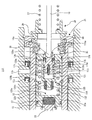
以下に、図2を用いて、第一の実施形態のハイドロブースタ10について説明する。ハイドロブースタ10は、液圧発生装置60によって発生された「アキュムレータ圧」をブレーキペダル71の操作に応じて調圧して「サーボ圧」を発生させ、当該「サーボ圧」から「マスタ圧」を発生させるものである。
(Hydro Booster)
Below, the
ハイドロブースタ10は、マスタシリンダ11、フェイルシリンダ12、第一マスタピストン13、第二マスタピストン14、入力ピストン15、オペロッド16、第一リターンスプリング17、第二リターンスプリング18、リザーバ19、ストッパ部材21、メカニカルリリーフバルブ22、スプールピストン23、スプールシリンダ24、スプールスプリング25、シミュレータスプリング26、ペダルリターンスプリング27、揺動部材28、第一スプリング受け29、第二スプリング受け30、連結部材31、移動部材32、保持ピストン33、シミュレータラバー34、受け部材35、フェイルスプリング36、緩衝部材37、第一スプールスプリング受け38、第二スプールスプリング受け39、押圧部材40、及びシール部材41〜49を有している。
The
なお、第一マスタピストン13が設けられている側を、ハイドロブースタ10の前方とし、オペロッド16が設けられている側を、ハイドロブースタ10の後方とする。つまり、ハイドロブースタ10(マスタシリンダ11)の軸線方向は、前後方向である。
The side on which the
マスタシリンダ11は、前端に底部11aを有し、後方に開口した有底筒状である。言い換えると、マスタシリンダ11は、前後方向に円柱形状の空間11pを有する。マスタシリンダ11は、車両に取り付けられている。マスタシリンダ11には、前方から後方に向かって順に、空間11p内に連通する、第一ポート11b、第二ポート11c、第三ポート11d、第四ポート11e、第五ポート11f(供給ポート)、第六ポート11g、第七ポート11hが形成されている。第二ポート11c、第四ポート11e、第六ポート11g、第七ポート11hは、ぞれぞれ、ブレーキフルードを貯留するリザーバ19と接続している。つまり、リザーバ19は、マスタシリンダ11の空間11pに接続されている。
The
マスタシリンダ11の内周面の第二ポート11cが設けられている位置の前後には、それぞれ、後述の第一マスタピストン13の外周面と全周に渡って接触するシール部材41、42が設けられている。また、マスタシリンダ11の内周面の第四ポート11eが設けられている位置の前後には、それぞれ、後述の第二マスタピストン14の外周面と全周に渡って接触する。シール部材43、44が設けられている。
Before and after the position where the second port 11c on the inner peripheral surface of the
また、マスタシリンダ11の内周面の第五ポート11fが設けられている位置の前後には、それぞれ、後述のフェイルシリンダ12の第一筒部12b及び第二筒部12cと全周に渡って接触するシール部材45、46が設けられている。また、マスタシリンダ11の内周面の第七ポート11hが設けられている位置の前後には、それぞれ、フェイルシリンダ12の第二筒部12cと全周に渡って接触するシール部材48、49が設けられている。
Further, before and after the position where the
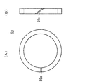
シール部材45の前方には、サポート部材59が設けられている。シール部材45とサポート部材59は、マスタシリンダ11の内部に凹陥形成された同一の保持凹部11j内に保持され、互いに接触している(図4示)。図3に示すように、サポート部材59は、割リングである。図3に示すように、サポート部材59には、スリット59aが形成されている。サポート部材59は、樹脂等の弾性を有する材料で構成されている。図4に示すように、サポート部材59の内周面は、後述のフェイルシリンダ12の第一筒部12bの外周面と接触している。
A
図2に示すように、第五ポート11f(供給ポート)は、マスタシリンダ11の外周面と空間11p内を連通している。第五ポート11fは、配管67によってアキュムレータ61に接続している。つまり、アキュムレータ61は、マスタシリンダ11の空間11pと接続されていて、第五ポート11fには、「アキュムレータ圧」が供給される。
As shown in FIG. 2, the
第五ポート11fと第六ポート11gは、連通流路11kによって連通している。連通流路11kには、メカニカルリリーフバルブ22が設けられている。メカニカルリリーフバルブ22は、第六ポート11gから第五ポート11fへのブレーキフルードの流通を阻止するとともに、第五ポート11fが規定圧力以上となった場合に、第五ポートfから第六ポート11gへのブレーキフルードの流通を許容する。
The
第一マスタピストン13は、マスタシリンダ11の空間11p内の前方(底部11aの後方)に、前後方向に摺動可能に設けられている。第一マスタピストン13は、円筒形状の筒部13aと、筒部13aの後方に筒部13aを閉塞するように形成された受け部13bとから構成された有底筒状である。筒部13aには、流通穴13cが形成されている。なお、受け部13bの前方側において、マスタシリンダ11の内周面、筒部13a、及び受け部13bによって囲まれる空間によって第一マスタ室10aが形成されている。第一ポート11bは、第一マスタ室10aに連通している。第一マスタ室10aは、ホイールシリンダWCfl、WCfr、WCrl、WCrrに供給されるブレーキフルードで満たされている。
The
マスタシリンダ11の底部11aと第一マスタピストン13の受け部13bとの間には、第一リターンスプリング17が設けられている。この第一リターンスプリング17によって、第一マスタピストン13が後方に付勢され、ブレーキペダル71が踏まれていない場合に、第一マスタピストン13が、図2に示す原位置に復帰するようになっている。
A
第一マスタピストン13が原位置に位置している状態では、第二ポート11cと流通穴13cとが合致し、リザーバ19と第一マスタ室10aが連通している。このため、リザーバ19から第一マスタ室10aにブレーキフルードが供給されるとともに、第一マスタ室10a内にある余剰のブレーキフルードがリザーバ19に戻される。第一マスタピストン13が原位置から前方に移動すると、第二ポート11cが筒部13aによって遮断され、第一マスタ室10aが密閉状態となり、第一マスタ室10aにおいて「マスタ圧」が発生する。
In the state where the
第二マスタピストン14は、マスタシリンダ11の空間11p内の第一マスタピストン13の後方に、前後方向に摺動可能に設けられている。第二マスタピストン14は、その前部に形成された円筒形状の第一筒部14aと、第一筒部14aの後方に形成された円筒形状の第二筒部14bと、第一筒部14aと第二筒部14bの接続部分において第一筒部14a及び第二筒部14bを閉塞するように形成された受け部14cとから構成されている。第一筒部14aには、流通穴14dが形成されている。
The
なお、受け部14cの前方において、受け部13b、マスタシリンダ11の内周面、第一筒部14a、及び受け部14cによって囲まれる空間によって第二マスタ室10bが形成されている。第三ポート11dは、第二マスタ室10bに連通している。第二マスタ室10bは、ホイールシリンダWCfl、WCfr、WCrl、WCrrに供給されるブレーキフルードで満たされている。
A
第一マスタピストン13の受け部13bと受け部14cとの間には、第一リターンスプリング17よりセット荷重の大きな第二リターンスプリング18が設けられている。この第二リターンスプリング18によって、第二マスタピストン14が後方に付勢され、ブレーキペダル71が踏まれていない場合に、第二マスタピストン14が、図2に示す原位置に復帰するようになっている。
A
第二マスタピストン14が原位置に位置している状態では、第四ポート11eと流通穴14dとが合致し、リザーバ19と第二マスタ室10bが連通している。このため、リザーバ19から第二マスタ室10bにブレーキフルードが供給されるとともに、第二マスタ室10b内にある余剰のブレーキフルードがリザーバ19に戻される。第二マスタピストン14が原位置から前方に移動すると、第四ポート11eが筒部14aによって遮断され、第二マスタ室10bが密閉状態となり、第二マスタ室10bにおいて「マスタ圧」が発生する。
In a state where the
フェイルシリンダ12は、マスタシリンダ11の空間11p内の第二マスタピストン14の後方に、前後方向摺動可能に設けられている。フェイルシリンダ12は、前方から後方に向かって、先端筒部12a、第一筒部12b、第二筒部12cが同軸に一体形成されている。先端筒部12a、第一筒部12b、第二筒部12cのいずれも円筒形状である。先端筒部12aの外径a、第一筒部12bの外径b、第二筒部12cの外径cの順に大きくなっている。先端筒部12aと第一筒部12bの間には、段差状となっていて押圧面12iが形成されている。
The
第二筒部12cの後端には、フランジ状の当接部12hが外側に延出形成されている。当接部12hが後述のストッパ部材21と当接し、フェイルシリンダ12がマスタシリンダ11から脱落しないようになっている。第二筒部12cの後部の内周面は他の部分比べて内径が大きくなっていて、段差面12jが形成されている。
At the rear end of the second
先端筒部12aは、第二マスタピストン14の第二筒部14b内に挿通している。第一筒部12bの後部には、第一筒部12bの外周面から内周面に連通する第一インナーポート12dが形成されている。第二筒部12cの前部には、第二筒部12cの外周面から内周面に連通する、第二インナーポート12e、第三インナーポート12fが形成されている。第二筒部12cの中間部には、第二筒部12cの外周面と内周面を連通し、フェイルシリンダ12内に設けられた入力ピストン15の前方に向けて開口する第四インナーポート12gが形成されている
The distal
図4に示すように、第二筒部12cの内周の前部には、ストッパ12mが突出形成されている。ストッパ12mには、前後方向に流路12nが連通形成されている。
As shown in FIG. 4, a
図2に示すように、入力ピストン15は、後述のスプールシリンダ24やスプールピストン23の後方において、フェイルシリンダ12の第二筒部12cの後部の内部(マスタシリンダ11の空間11p内)に前後方向摺動可能に設けられている。入力ピストン15は、断面円形状を有する略円柱形状である。入力ピストン15の後端には、底部が円錐状に凹陥したロッド受け部15aが形成されている。入力ピストン15の前部には、スプリング受け部15bが凹陥形成されている。入力ピストン15の後部は他の部分と比べて外径が小さくなっていて、段差面15eが形成されている。
As shown in FIG. 2, the
入力ピストン15の外周面には、シール保持凹部15c、15dが凹陥形成されている。シール保持凹部15c、15dには、フェイルシリンダ12の第二筒部12cの内周面と全周に渡って接触するシール部材55、56が取り付けられている。
Seal holding recesses 15 c and 15 d are formed in the outer peripheral surface of the
入力ピストン15は、オペロッド16及び連結部材31を介して、ブレーキペダル71に連結されている。このため、入力ピストン15には、ブレーキペダル71からの操作力が、連結部材31及びオペロッド16を介して伝達される。また、入力ピストン15は、伝達された操作力を、シミュレータスプリング26、移動部材32、シミュレータラバー34、保持ピストン33、緩衝部材37を介して、スプールピストン23に伝達して、スプールピストン23を駆動する。
The
図9に示すように、受け部材35は、円筒部35aと、円筒部35aの前端から内側に延出するリング状の受け部35bとから構成されている。受け部材35は、受け部35bの前端面が、第二筒部12cの段差面12j及び入力ピストン15の段差面15eと当接して、第二筒部12cの内部の後端部に設けられている。
As shown in FIG. 9, the receiving
ストッパ部材21は、マスタシリンダ11の内部の後部に摺動可能に設けられている。ストッパ部材21は、リング状の基部21aと、基部の前面から前方に突出する円筒形状の円筒部21bと、円筒部21bの前端から内側に延出したリング状のストッパ部21cから構成されている。
The
円筒部21bの内側の基部21aの前面には、受け面21dが形成されている。受け面21dにフェイルシリンダ12の当接部12hが当接している。基部21aの前面の受け面21dよりも内側にはリング状に凹陥した保持凹部21fが形成されている。この保持凹部21fに、受け部材35の円筒部35aの後端が挿通している。基部21aの前面の保持凹部21fよりも内側にはリング状に前方に突出した突出部21gが形成されている。
A receiving
基部21aの後端面の中心には、球面状に凹陥した形状の受け穴21eが形成されている。マスタシリンダ11の内部の後端、つまり、マスタシリンダ11の開口部には、Cリング86が取り付けられている。このCリング86によって、ストッパ部材21のマスタシリンダ11からの脱落が防止される。
A receiving
揺動部材28は、リング状である。揺動部材28の前部には、受け穴21eと合致する球面状の押圧面28aが形成されている。押圧面28aが受け穴21eに密接して、揺動部材28がストッパ部材21の後方に設けられている。揺動部材28はストッパ部材21に対して揺動可能である。
The
フェイルスプリング36は、受け部材35の円筒部35a内において、受け部材35の受け部35bとストッパ部材21の突出部21gの間に設けられている。本実施形態では、フェイルスプリング36は、複数のダイヤフラムスプリングである。このような構成によって、フェイルスプリング36は、フェイルシリンダ12をマスタシリンダ11に対して前方に付勢している。
The
第一スプリング受け29は、円筒部29aと、円筒部29aの前端に、内側及び外側に延出形成されたフランジ状のフランジ部29bとから構成されている。フランジ部29bが揺動部材28の後端面に密接して、第一スプリング受け29が揺動部材28の後方に設けられている。
The
オペロッド16の前端には、球状の押圧部16aが形成されている。オペロッド16の後端には、ネジ部16bが形成されている。押圧部16aがロッド受け部15aに挿通して、オペロッド16が入力ピストン15の後端に連結している。なお、オペロッド16の長手方向は、前後方向となっている。オペロッド16は、揺動部材28及び第一スプリング受け29に挿通している。
A spherical
第二スプリング受け30は、第一スプリング受け29と対向して、第一スプリング受け29の後方に設けられている。第二スプリング受け30は、その後端に形成された底部30aと、底部30aから前方に形成された筒部30bとから構成された有底筒状である。底部30aにはネジ穴30cが形成されている。ネジ穴30cに、オペロッド16のネジ部16bが螺着している。
The
ペダルリターンスプリング27は、第一スプリング受け29のフランジ部29bと第二スプリング受け30の底部30aとの間に設けられている。ペダルリターンスプリング27は、第一スプリング受け29の円筒部29aと第二スプリング受け30の筒部30bの内側で保持されている。
The
連結部材31の前端には、ネジ穴31aが形成されている。ネジ穴31aにオペロッド16のネジ部16bが螺着して、連結部材31がオペロッド16の後端に連結されている。第二スプリング受け30の底部30aは、連結部材31の前端と当接している。連結部材31の前後方向中間部分には、軸穴31bが連通形成されている。第二スプリング受け30のネジ穴30cと連結部材31のネジ穴31aがオペロッド16のネジ部16bと螺着している。このような構造により、連結部材31のオペロッド16に対する前後方向位置が調整可能となっている。
A
ブレーキペダル71は、運転者の踏力(操作力)が伝達されるレーバー状の部材である。ブレーキペダル71の中間部分には、軸穴71aが形成されている。ブレーキペダル71の上端には、取付穴71bが形成されている。取付穴71bにボルト81が挿通して、取付穴71bを揺動中心として、ブレーキペダル71が車両の取付部(図2に示す一点鎖線)に揺動可能に取り付けられている。軸穴71aと、連結部材31の軸穴31bに、連結ピン82が挿通して、ブレーキペダル71が連結部材31に揺動可能に連結されている。
The
ペダルリターンスプリング27の付勢力によって、第二スプリング受け30及び連結部材31が後方に付勢され、ブレーキペダル71が図2に示す原位置に復帰するようになっている。ブレーキペダル71が踏み込まれると、ブレーキペダル71は取付穴71bを揺動中心として揺動し、軸穴71a、31bもまた取付穴71bを揺動中心として揺動するなお、図2に示す二点鎖線は、軸穴71a、31bの軌跡である。図2の二点鎖線で示すように、ブレーキペダル71が踏み込まれるに従って、軸穴71a、31bの位置は上方に移動する。すると、揺動部材28及び第一スプリング受け29はストッパ部材21に対して揺動し、ペダルリターンスプリング27に無理な力、つまり、せん断方向の力が作用しないようになっている。
Due to the urging force of the
図2に示すように、保持ピストン33は、フェイルシリンダ12の第二筒部12cの内部の前方に(マスタシリンダ11の空間11p内に)前後方向摺動可能に設けられている。保持ピストン33は、その前部に形成された底部33aと、底部33aの後方に形成された筒部33bとから構成された有底筒状である。底部33aの前端面には保持凹部33cが凹陥形成されている。図4に示すように、保持凹部33cの内周面の前端部分には、Cリング溝33eが全周に渡って凹陥形成されている。筒部33bの外周面には、シール保持凹部33dが凹陥形成されている。シール保持凹部33dには、フェイルシリンダ12の第二筒部12cの内周面と全周に渡って接触するシール部材75が取り付けられている。
As shown in FIG. 2, the holding
図2に示すように、移動部材32は、フェイルシリンダ12の第二筒部12c内(マスタシリンダ11の空間11p内)の保持ピストン33の後方に、前後方向摺動可能に設けられている。移動部材32は、その前端部に形成されたフランジ状のフランジ部32aと、フランジ部32aの後方に形成された軸部32bとから構成されている。
As shown in FIG. 2, the moving
フランジ部32aの前端面には、ラバー受け凹部32cが凹陥形成されている。ラバー受け凹部32cには、円柱形状のシミュレータラバー34が取り付けられている。シミュレータラバー34は、フランジ部32aから前方に突出している。原位置では、シミュレータラバー34(移動部材32)は保持ピストン33と離間している。
A
フランジ部32aには、フランジ部32a前方と保持ピストン33間に形成される空間と後述の離間室10fとを連通する流路32hが形成されている。このため、移動部材32が保持ピストン33に対して摺動した場合に、前記空間と離間室10f間においてブレーキフルードが相互に流通し、移動部材32の保持ピストン33に対する摺動が阻害されない。
The
フェイルシリンダ12の第二筒部12c、保持ピストン33、入力ピストン15により囲まれる空間によってシミュレータ室10fが形成されている。シミュレータ室10f内には、ブレーキフルードが満たされている。
A simulator chamber 10 f is formed by a space surrounded by the
シミュレータスプリング26は、シミュレータ室10f内において、移動部材32のフランジ部32aと入力ピストン15のスプリング受け部15bとの間に設けられている。つまり、シミュレータスプリング26は、フェイルシリンダ12の第二筒部12c内(マスタシリンダ11の空間11p内)において、入力ピストン15の前方に設けられている。シミュレータスプリング26内に移動部材32の軸部32bが挿通し、シミュレータスプリング26が軸部32bで保持されている。本実施形態では、シミュレータスプリング26の前部は、移動部材32の軸部32bに圧入されている。このような構成により、シミュレータラバー34(移動部材32)が保持ピストン33に当接した状態から更に入力ピストン15が前方に移動した場合に、シミュレータスプリング26によって入力ピストン15を後方に付勢される。
The
第一インナーポート12dは、フェイルシリンダ12の第一筒部12bの外周面に向けて開口している。上述したように、第二筒部12cの外径cは第一筒部12bの外径bよりも大きい。このため、第五ポート11fに「アキュムレータ圧」が作用すると、当該「アキュムレータ圧」及び第一筒部12bと第二筒部12cとの断面積差により、フェイルシリンダ12には後方への力が作用してストッパ部材21に押し付けられ、フェイルシリンダ12がその摺動範囲の最後端の原位置に位置される。
The first
フェイルシリンダ12が原位置にある状態では、第四インナーポート12gは、マスタシリンダ11の第七ポート11hと連通している。このように、シミュレータ室10fとリザーバ19は、第四インナーポート12gと第七ポート11hとからなる「リザーバ流路」によって連通し、入力ピストン15の前後方向の摺動に伴い、シミュレータ室10fの容積が変化した場合には、シミュレータ室10f内のブレーキフルードがリザーバ19に戻され、又は、リザーバ19からブレーキフルードがシミュレータ室10fに供給される。このため、入力ピストン15の前後方向の摺動が阻害されない。
In a state where the
図4に示すように、スプールシリンダ24は、フェイルシリンダ12の第一筒部12b内(マスタシリンダ11の空間11p内)の第二マスタピストン14の後方に固定されている。スプールシリンダ24は、円筒形状である。スプールシリンダ24の外周面には、シール保持凹部24a、24bが凹陥形成されている。シール保持凹部24a、24bには、第一筒部12bの内周面と全周に渡って接触するシール部材57、58が保持されている。これらシール部材57、58と第一筒部12bの内周面との摩擦力により、スプールシリンダ24の第一筒部12bに対する前方への移動が阻止される。スプールシリンダ24の後端がストッパ12mに当接して、スプールシリンダ24の後方への移動が阻止される。
As shown in FIG. 4, the
スプールシリンダ24には、スプールシリンダ24の外周面と内周面を連通するスプールポート24cが形成されている。スプールポート24cは、第一インナーポート12dと連通している。スプールポート24cよりも後方のスプールシリンダ24の内周面には、第一スプール凹部24dが全周に渡って凹陥形成されている。第一スプール凹部24dよりも後方のスプールシリンダ24の内周面には、第二スプール凹部24fが全周に渡って凹陥形成されている。
The
シール保持凹部24bよりも後方のスプールシリンダ24の外周面には、流通凹部24eが全周に渡って凹陥形成されている。第三インナーポート12fは、流通凹部24eに向けて開口している。従って、流通凹部24eは、第三インナーポート12f及び第六ポート11gを介して、リザーバ19に連通している。
On the outer peripheral surface of the
スプールピストン23は、断面円形状を有する円柱形状である。スプールピストン23は、スプールシリンダ24内に前後方向摺動可能に挿通している。スプールピストン23の後端は、他の部分と比べて外径が大きい固定部23aが形成されている。スプールピストン23の固定部23aが保持ピストン33の保持凹部33cに挿通している。そして、保持ピストン33のCリング溝33eにCリング85が係合して、スプールピストン23の保持ピストン33の保持凹部33cからの前方への脱落が防止されて、スプールピストン23が前後方向摺動可能に保持ピストン33に保持されている。なお、固定部23aを他の部分から分割したスプールピストン23であっても差し支え無い。
The
保持凹部33cの底部とスプールピストン23の後端面との間には、緩衝部材37が設けられている。緩衝部材37は、本実施形態では、弾性を有する円柱形状のゴムで構成されているが、コイルスプリングやダイヤフラムスプリング等の付勢部材であっても差し支え無い。
A
スプールピストン23の外周面の前後方向中間位置には、全周に渡って第三スプール凹部23bが凹陥形成されている。第三スプール凹部23bの後方位置のスプールピストン23の外周面には、全周に渡って第四スプール凹部23cが凹陥形成されている。スプールピストン23には、その前端から中間よりもやや後方位置まで、流通穴23eが形成されている。スプールピストン23には、第四スプール凹部23cと流通穴23eを連通する第一流通ポート23d、第二流通ポート23fが形成されている。
A
図2に示すように、第二マスタピストン14の受け部14cの後方のマスタシリンダ11の空間11p内において、第二マスタピストン14、マスタシリンダ11の空間11p、スプールピストン23の前端、スプールシリンダ24の前端で囲まれる空間が、サーボ室10cである。
As shown in FIG. 2, in the
図2に示すように、第一スプールスプリング受け38は、受け部38a、取付部38b、とから構成されている。受け部38aは、円板状である。受け部38aは、フェイルシリンダ12の先端筒部12aの開口部を閉塞するように、先端筒部12a内の前方に取り付けられている。取付部38bは、円筒形状であり、受け部38aの前面の中心から前方に突出形成されている。取付部38bの内周面には、ネジ溝が形成されている。受け部38aの後面の中心には後方に当接部38cが突出形成されている。受け部38aには、前後方向に連通する流通穴38dが形成されている。
As shown in FIG. 2, the first
押圧部材40は、棒状である。押圧部材40の後部は、取付部38bのネジ溝に螺着している。 The pressing member 40 has a rod shape. The rear portion of the pressing member 40 is screwed into the thread groove of the attachment portion 38b.
図4に示すように、第二スプールスプリング受け39は、その前端に底部39cを有する有底筒状の本体部39aと、本体部39aの後端に外側に延出形成されたリング状の受け部39bとから構成されている。本体部39aの内周面にスプールピストン23の前端が嵌合して、第二スプールスプリング受け39がスプールピストン23の先端に取り付けられている。底部39cには連通穴39dが形成されている。図2に示すように、第二スプールスプリング受け39は、第一スプールスプリング受け38の当接部38cと所定距離離間して対向している。
As shown in FIG. 4, the second
図2や図4に示すように、スプールスプリング25は、第一スプールスプリング受け38の受け部38aと、第二スプールスプリング受け39の受け部39bの間に設けられている。スプールスプリング25によって、スプールピストン23はフェイルシリンダ12(マスタシリンダ11)やスプールシリンダ24に対して後方に付勢されている。
As shown in FIGS. 2 and 4, the
シミュレータスプリング26のバネ定数は、スプールスプリング25のバネ定数よりも大きく設定されている。また、シミュレータスプリング26のバネ定数は、ペダルリターンスプリング27のバネ定数よりも大きく設定されている。
The spring constant of the
(シミュレータ)
以下に、シミュレータスプリング26、ペダルリターンスプリング27、及びシミュレータラバー34から構成される「シミュレータ」について説明する。「シミュレータ」は、ブレーキペダル71のストロークに応じて、ブレーキペダル71に荷重(反力)を発生させ、通常のブレーキ装置の操作感(踏力感)を再現する機構である。
(Simulator)
Hereinafter, a “simulator” including the
ブレーキペダル71が踏まれると、まず、ペダルリターンスプリング27が縮む。この際に、ブレーキペダル71に作用する反力は、ペダルリターンスプリング27のセット荷重に、ペダルリターンスプリング27のバネ定数にブレーキペダル71(連結部材31)のストロークを乗算した値を加えた値となる(図8の(1))。
When the
更にブレーキペダル71が踏み込まれ、シミュレータラバー34が保持ピストン33に当接すると、ペダルリターンスプリング27及びシミュレータスプリング26が縮む。この際にブレーキペダル71に作用する反力は、シミュレータスプリング26及びペダルリターンスプリング27の発生荷重の合成値となる(図8の(2))。このため、シミュレータラバー34が保持ピストン33に当接する前(図8の(1))と比較して、ブレーキペダル71のストロークあたりのブレーキペダル71に作用する反力の増加量が大きくなる。
When the
なお、シミュレータラバー34が存在する為、実際にはシミュレータラバー34が保持ピストン33に当接してから、更にブレーキペダル71が踏まれると、シミュレータラバー34が圧縮される。シミュレータラバー34は、その性質から、圧縮されるに従って徐々にバネ定数が上昇する。このため、図8の(3)に示すように、シミュレータラバー34が保持ピストン33に当接する前後において、ブレーキペダル71のストローク当たりのブレーキペダル71に作用する反力が徐変し、前記反力の急変に伴う運転者の違和感が抑制される。
Since the simulator rubber 34 exists, the simulator rubber 34 is actually compressed when the
なお、シミュレータラバー34は、移動部材32と保持ピストン33との当接部分に取り付けられていればよく、保持ピストン33の後端に取り付けられていても差し支え無い。このような実施形態であっても、ブレーキペダル71のストローク当たりのブレーキペダル71に作用する反力が徐変する。
The simulator rubber 34 only needs to be attached to the contact portion between the moving
このように、シミュレータラバー34が保持ピストン33に当接するまで、ブレーキペダル71のストロークあたりのブレーキペダル71に作用する反力の増加量が小さく(図8の(1))、シミュレータラバー34が保持ピストン33に当接した後は、ブレーキペダル71のストロークあたりのブレーキペダル71に作用する反力の増加量が大きくなり(図8の(2))、通常のブレーキ装置の操作感が再現されるようになっている。
Thus, until the simulator rubber 34 contacts the
(調圧装置)
調圧装置53は、マスタ室10a、10bから供給されるブレーキフルードの「マスタ圧」を増圧又は減圧して、ホイールシリンダWCfl、WCfr、WCrl、WCrrに「ホイールシリンダ圧」を供給するものであり、周知のアンチロックブレーキ制御や横滑り防止制御を実現するものである。第一マスタ室10aの第一ポート11bには、配管52、調圧装置53を介してホイールシリンダWCfr、WCflが連通されている。また、第二マスタ室10bの第三ポート11dには、配管51、調圧装置53を介してホイールシリンダWCrr、WCrlが連通されている。
(Pressure regulator)
The
ここで、調圧装置53について、4つのホイールシリンダのうち1つ(WCfr)に「ホイールシリンダ圧」を供給する構成について説明し、他の構成については同様であるため説明を省略する。調圧装置53は、保持弁531、減圧弁532、調圧リザーバ533、ポンプ534、モータ535、液圧制御弁536を備えている。保持弁531は、常開型の電磁弁であり、ブレーキECU6により開閉が制御される。保持弁531は、一方が液圧制御弁536に接続され、他方がホイールシリンダWCfr及び減圧弁532に接続されるように設けられている。
Here, the configuration of supplying the “wheel cylinder pressure” to one of the four wheel cylinders (WCfr) in the
減圧弁532は、常閉型の電磁弁であり、ブレーキECU6により開閉が制御される。減圧弁532は、一方がホイールシリンダWCfr及び保持弁531に接続され、他方が第一流路157によって調圧リザーバ533の貯留室533eに接続されている。減圧弁532が開状態となると、ホイールシリンダWCfrと調圧リザーバ533の貯留室533eが連通し、ホイールシリンダWCfrの「ホイールシリンダ圧」が低下する。
The
液圧制御弁536は、常開型の電磁弁であり、ブレーキECU6により制御される。液圧制御弁536は、一方が第一マスタ室10aに接続され、他方が保持弁531に接続されている。液圧制御弁536が通電されると、差圧状態となり、「ホイールシリンダ圧」が「マスタ圧」よりも所定圧以上高くなった場合にのみ、ホイールシリンダWCfr側から第一マスタ室10a側へのブレーキフルードの流通が許容される。
The
調圧リザーバ533は、シリンダ533a、ピストン533b、スプリング533c、流路調整弁533dとから構成されている。シリンダ533a内には、ピストン533bが摺動可能に設けられている。シリンダ533aとピストン533bによって囲まれた空間によって貯留室533eが形成されている。ピストン533bが摺動することにより、貯留室533eの容積が変化する。貯留室533e内にはブレーキフルードが貯留されている。スプリング533cは、シリンダ533aの底部とピストン533bの間の空間に設けられていて、貯留室533eの容積を減少させる方向にピストン533bを付勢している。
The
配管52の液圧制御弁536よりも第一マスタ室10a側は、第二流路158及び流路調整弁533dを介して貯留室533eに接続している。貯留室533e内の圧力が高まるに従って、つまり貯留室533eの容積が増大する方向にピストン533bが摺動するに従って、流路調整弁533dによって貯留室533eと第二流路158の間の流路が絞られる。
The
ポンプ534は、ブレーキECU6の指令に応じたモータ535の作動によって駆動される。ポンプ534の吸込口は、第三流路159を介して貯留室533eに接続されている。ポンプ534の吐出口は、逆止弁zを介して、液圧制御弁536と保持弁531の間の配管52に接続されている。ここでの逆止弁zは、ポンプ534から配管52(第一マスタ室10a)への流れを許容し、その逆方向の流れを規制する。なお、ポンプ534が吐出したブレーキフルードの脈動を緩和するために、ポンプ534の上流側にはダンパ(図示せず)が設けられていてもよい。
The
第一マスタ室10aにおいて「マスタ圧」が発生していない状態では、第二流路158を介して第一マスタ室10aと接続している貯留室533e内の圧力が高くないので、流路調整弁533dによって第二流路158と貯留室533e間の流路が絞られていない。このため、ポンプ534は第一マスタ室10aから第二流路158及び貯留室533eを介してブレーキフルードを吸入することができる。
When the “master pressure” is not generated in the
一方で、第一マスタ室10aにおいて「マスタ圧」が上昇すると、当該「マスタ圧」が第二流路158を介してピストン533bに作用する力によって、流路調整弁533dが作動して、流路調整弁533dによって貯留室533eと第二流路158の間の流路が絞られて閉塞される。
On the other hand, when the “master pressure” rises in the
この状態で、ポンプ534が駆動されると、貯留室533e内のブレーキフルードがポンプ534によって吐出される。そして、所定量以上のブレーキフルードが貯留室533eからポンプ534に供給されると、流路調整弁533dによって閉塞されている貯留室533eと第二流路158の間の流路が微少に開き、ブレーキフルードが第一マスタ室10aから第二流路158を介して貯留室533eに供給され、次いで、ポンプ534に供給される。
When the
調圧装置53の減圧モード時においては、減圧弁532が開状態とされ、ホイールシリンダWCfrの「ホイールシリンダ圧」が低下する。そして、液圧制御弁536が開状態とされ、ポンプ534はホイールシリンダWCfr内のブレーキフルード又は貯留室533e内に貯留されているブレーキフルードを吸い込んで第一マスタ室10aに戻す。
When the
調圧装置53の増圧モード時においては、保持弁531が開状態、液圧制御弁536が差圧状態とされ、ポンプ534は第一マスタ室10a内のブレーキフルード及び貯留室533e内に貯留されているブレーキフルードをホイールシリンダWCfrに供給し、ホイールシリンダWCfrにおいて「ホイールシリンダ圧」を発生させる。
In the pressure increasing mode of the
調圧装置53の保持モード時においては、保持弁531が閉状態、又は液圧制御弁536が差圧状態とされ、ホイールシリンダWCfrの「ホイールシリンダ圧」が保持される。
In the holding mode of the
このように、調圧装置53によって、ブレーキペダル71の操作に関わらず、「ホイールシリンダ圧」を調整することがきる。ブレーキECU6は、「マスタ圧」、車輪速度の状態、及び前後加速度に基づき、各電磁弁531、532の開閉を切り換え制御し、モータ535を必要に応じて作動してホイールシリンダWCfrに付与する「ホイールシリンダ圧」を調整し、アンチロックブレーキ制御や横滑り防止制御を実行する。
Thus, the “wheel cylinder pressure” can be adjusted by the
(ハイドロブースタの動作)
以下に、ハイドロブースタ10の動作について説明する。ブレーキペダル71に入力される操作力(ペダル荷重)に応じて、スプールシリンダ24及びスプールピストン23からなる「スプール弁」が駆動され、ハイドロブースタ10が「減圧モード」、「増圧モード」、「保持モード」のいずれかに切り替えられる。
(Operation of hydro booster)
Below, operation | movement of the
[減圧モード]
ブレーキペダル71が踏まれていない状態や、ブレーキペダル71に入力される操作力(踏力)が摩擦制動力発生操作力P2(図5示)以下の場合には、「減圧モード」となる。図2に示すように、ブレーキペダル71が踏まれていない状態では、つまり、「減圧モード」では、シミュレータラバー34(移動部材32)と保持ピストン33の底部33aは離間している。
[Decompression mode]
When the
シミュレータラバー34と保持ピストン33の底部33aは離間している状態では、スプールピストン23は、スプールスプリング25の付勢力により、スプールピストン23の摺動範囲の最後部の「減圧位置」(図4示)に位置している。この状態では、図4に示すように、スプールポート24cが、スプールピストン23の外周面によって閉塞されている。つまり、アキュムレータ61からの「アキュムレータ圧」が、サーボ室10cに作用しない。
In a state where the simulator rubber 34 and the bottom 33a of the holding
また、図4に示すように、スプールピストン23の第四スプール凹部23cはスプールシリンダ24の第二スプール凹部24fと連通している。つまり、サーボ室10cは、流通穴23e、第一流通ポート23d、第四スプール凹部23c、第二スプール凹部24f、流路12n、流通凹部24e、第三インナーポート12f、及び第六ポート11gからなる「減圧流路」を介してリザーバ19に連通している。このため、「減圧モード」では、サーボ室10cは大気圧と同一であり、第一マスタ室10a及び第二マスタ室10bにおいて「マスタ圧」は発生しない。
As shown in FIG. 4, the
ブレーキペダル71が踏まれて、シミュレータラバー34が保持ピストン33の底部33aに当接し、保持ピストン33を介してスプールピストン23に前方への入力荷重が作用しても、当該入力荷重が、スプールスプリング25の付勢力よりも小さい場合には、スプールピストン23は、前方に移動することなく「減圧位置」に位置している。なお、上記入力荷重は、ブレーキペダル71の操作により、連結部材31に入力される荷重から、当該操作力によりペダルリターンスプリング27が圧縮されるのに必要な荷重を減算した力である。ブレーキペダル71に入力される操作力が摩擦制動力発生操作力P2以下の状態では、ハイドロブースタ10は「増圧モード」とならず、「サーボ圧」及び「マスタ」が発生することなく、摩擦ブレーキ装置Bfl、Bfr、Brl、Brrにおいて「摩擦制動力」が発生しないように設定されている。
Even if the
[増圧モード]
ブレーキペダル71に入力される操作力が摩擦制動力発生操作力P2より大きくなると、ハイドロブースタ10は「増圧モード」となる。つまり、ブレーキペダル71に入力される操作力により、保持ピストン33がシミュレータラバー34(移動部材32)によって押圧され、スプールピストン23に前方への荷重が作用すると、スプールピストン23がスプールスプリング25の付勢力に抗して、スプールピストン23の摺動範囲の前方の「増圧位置」に移動する(図6の状態)。
[Pressure increase mode]
When the operation force input to the
図6に示すように、スプールピストン23が「増圧位置」に位置している状態では、第一流通ポート23dはスプールシリンダ24の内周面によって閉塞され、第一流通ポート23dと第二スプール凹部24fは遮断される。このため、サーボ室10cとリザーバ19は遮断される。
As shown in FIG. 6, in the state where the
また、スプールピストン23が「増圧位置」に位置している状態では、スプールポート24cは、第三スプール凹部23bに連通している。また、第三スプール凹部23b、第一スプール凹部24d、及び第四スプール凹部23cは相互に連通している。このため、アキュムレータ61からの「アキュムレータ圧」が、第一インナーポート12d、スプールポート24c、第三スプール凹部23b、第一スプール凹部24d、第四スプール凹部23c、第二流通ポート23f、流通穴23e、連通穴39dからなる「増圧流路」を介して、サーボ室10cに供給され、「サーボ圧」が上昇する。
Further, when the
「サーボ圧」が上昇すると、「サーボ圧」によって第二マスタピストン14が前方に移動し、第二リターンスプリング18によって押圧された第一マスタピストン13も前方に移動する。すると、第二マスタ室10b及び第一マスタ室10aに「マスタ圧」が発生する。「サーボ圧」の上昇に従って、「マスタ圧」が上昇する。本実施形態では、第二マスタピストン14の前後両側のシール径、及び第一マスタピストン13の前後両側のシール径は同一となっている。従って、「サーボ圧」と第二マスタ室10b及び第一マスタ室10aで発生する「マスタ圧」は同一となる。
When the “servo pressure” increases, the
第二マスタ室10b及び第一マスタ室10aで「マスタ圧」が発生すると、第二マスタ室10b及び第一マスタ室10aから配管51、52、調圧装置53を介してホイールシリンダWCfr、WCfl、WCrr、WCrlにブレーキフルードが供給され、ホイールシリンダWCfr、WCfl、WCrr、WCrlにおいて「ホイールシリンダ圧」が発生し、摩擦制動力が発生する。
When “master pressure” is generated in the
[保持モード]
スプールピストン23が「増圧位置」に位置している状態では、サーボ室10cに「アキュムレータ圧」が作用し「サーボ圧」が上昇する。すると、スプールピストン23には、「サーボ圧」にスプールピストン23の断面積(シール面積)を乗じた復帰力が後方に作用する。復帰力及びスプールスプリング25の付勢力の合力がスプールピストン23に作用する入力荷重よりも大きくなると、スプールピストン23は、後方に移動し、「減圧位置」と「増圧位置」の間の位置である「保持位置」に位置される(図7の状態)。
[Retention mode]
In a state where the
図7に示すように、スプールピストン23が「保持位置」に位置している状態では、スプールポート24cは、スプールピストン23の外周面によって閉塞される。また、第四スプール凹部23cは、スプールシリンダ24の内周面によって閉塞される。このため、スプールポート24cと第二流通ポート23fは遮断され、サーボ室10cとアキュムレータ61は遮断され、サーボ室10cに「アキュムレータ圧」が作用しない。
As shown in FIG. 7, in a state where the
また、第四スプール凹部23cは、スプールシリンダ24の内周面によって閉塞されているので、第一流通ポート23dと第二スプール凹部24fは遮断され、サーボ室10cとリザーバ19が遮断される。すると、サーボ室10c密閉状態となり、「増圧モード」から「保持モード」に切り替わる際の「サーボ圧」が維持される。
Further, since the
スプールピストン23に作用する復帰力及びスプールスプリング25の付勢力の合力が、スプールピストン23に作用する入力荷重がつり合うと、「保持モード」が維持される。一方で、ブレーキペダル71への操作力が減少して、スプールピストン23に作用する入力荷重が減少し、スプールピストン23に作用する復帰力及びスプールスプリング25の付勢力の合力が、スプールピストン23に作用する入力荷重よりも大きくなると、スプールピストン23が後方に移動して「減圧位置」(図4示)に位置し「減圧モード」となり、サーボ室10cの「サーボ圧」が減少する。
When the resultant force of the restoring force acting on the
一方で、スプールピストン23が「保持位置」に位置している状態で、ブレーキペダル71に入力される操作力が増大して、スプールピストン23に作用する操作力が増大し、スプールピストン23に作用する入力荷重が、スプールピストン23に作用する復帰力及びスプールスプリング25の付勢力の合力よりも大きくなると、スプールピストン23が前方に移動して「増圧位置」(図6示)に位置し「増圧モード」となり、サーボ室10cの「サーボ圧」が増大する。
On the other hand, when the
なお、スプールピストン23の外周面とスプールシリンダ24の内周面との摺動抵抗等の抵抗により、スプールピストン23の移動にはヒステリシスが発生し、当該ヒステリシスによってスプールピストン23の前後方向の移動が阻害される。このため、「保持モード」から「減圧モード」、或いは「保持モード」から「増圧モード」に頻繁に切り替わらないようになっている。
In addition, hysteresis occurs in the movement of the
(回生制動力と摩擦制動力の関係)
以下に図5を用いて、回生制動力と摩擦制動力の関係について説明する。ブレーキペダル71に入力される操作力が摩擦制動力発生操作力P2以下では、ハイドロブースタ10は「減圧モード」から「増圧モード」切り替わらず、摩擦制動力は発生しない。図5に示すように、摩擦制動力発生操作力P2よりも小さい操作力である回生制動力発生操作力P1が設定されている。
(Relationship between regenerative braking force and friction braking force)
The relationship between the regenerative braking force and the friction braking force will be described below with reference to FIG. When the operation force input to the
本実施形態では、ブレーキペダル71に入力される操作力は、ブレーキセンサ72によって検出される。つまり、図8に示すように、ブレーキペダル71に入力される操作力(ブレーキペダル荷重)と、ブレーキペダル71のストロークとは相関関係が有るので、ブレーキECU6は、ブレーキセンサ72の検出値から、回生制動力発生操作力P1を超えたか否かを判断することができる。
In the present embodiment, the operating force input to the
図5に示すように、ブレーキペダル71が踏まれて、ブレーキECU6が、ブレーキペダル71に入力された操作力が回生制動力発生操作力P1を超えたと判断した場合には、上述したようにブレーキセンサ72の検出値に基づいて、「目標回生制動力」を演算する。そして、ブレーキECU6は、「目標回生制動力」をハイブリッドECU9に出力する。
As shown in FIG. 5, when the
ハイブリッドECU9は、車速V、バッテリ507の充電状態、及び「目標回生制動力」から、回生ブレーキ装置Aにおいて実際に発生させることができる「実行回生制動力」を演算する。ハイブリッドECU9は、回生ブレーキ装置Aにおいて「実行回生制動力」を発生させる。
The hybrid ECU 9 calculates an “executed regenerative braking force” that can be actually generated in the regenerative braking device A from the vehicle speed V, the state of charge of the
一方で、ハイブリッドECU9が、「実行回生制動力」が「目標回生制動力」に達しないと判断した場合には、「目標回生制動力」から「実行回生制動力」を減算して「調整摩擦制動力」を演算する。なお、「実行回生制動力」が「目標回生制動力」に達しない場合には、車速Vが所定速度以下となった場合や、バッテリ507が満充電に近い場合が含まれる。ハイブリッドECU9は、「調整摩擦制動力」をブレーキECU6に出力する。
On the other hand, when the hybrid ECU 9 determines that the “executed regenerative braking force” does not reach the “target regenerative braking force”, the “executed regenerative braking force” is subtracted from the “target regenerative braking force” to obtain “adjustment friction”. "Braking force" is calculated. It should be noted that the case where the “execution regenerative braking force” does not reach the “target regenerative braking force” includes the case where the vehicle speed V is equal to or lower than a predetermined speed or the case where the
ブレーキECU6は、調圧装置53を制御して、「ホイールシリンダ圧」を調整させて、摩擦ブレーキ装置Bfl、Bfr、Brl、Brrにおいて「調整摩擦制動力」を余剰に発生させる。このように、「実行回生制動力」が「目標回生制動力」に達しない場合であっても、調圧装置53の作動により、「調整摩擦制動力」を余剰に発生させることにより、回生制動力と摩擦制動力の合計である総制動力が変わらないようになっている。
The
このように、回生ブレーキ装置Aにおいて回生制動力を十分に発生させることができない場合には、調圧装置53が「ホイールシリンダ圧」を調整することにより、不足分の回生制動力に相当する摩擦制動力を摩擦ブレーキ装置Bfl、Bfr、Brl、Brrにおいて発生させることができる。
As described above, when the regenerative braking device A cannot sufficiently generate the regenerative braking force, the
(液圧発生装置故障時のハイドロブースタの動作)
液圧発生装置60の故障により、「アキュムレータ圧」が消失した場合には、フェイルスプリング36の付勢力により、フェイルシリンダ12が前方に付勢されて、フェイルシリンダ12の当接部12hがストッパ部材21のストッパ部21cに当接する位置までフェイルシリンダ12が前方に移動される。この状態では、フェイルシリンダ12の第二筒部12cによって、マスタシリンダ11の第七ポート11hが遮断されて、シミュレータ室10fが油密状態となる。
(Operation of the hydro booster when the hydraulic pressure generator fails)
When the “accumulator pressure” disappears due to a failure of the
シミュレータ室10fが油密状態であるので、ブレーキペダル71が踏まれると、ブレーキペダル71に入力された操作力は、連結部材31、オペロッド16を介し、入力ピストン15から保持ピストン33に伝達され、保持ピストン33、スプールピストン23及び第二スプールスプリング受け39が前進する。
Since the simulator chamber 10f is in an oil-tight state, when the
保持ピストン33がフェイルシリンダ12内部のストッパ12mに当接すると、ブレーキペダル71に入力された操作力が、ストッパ12mを介してフェイルシリンダ12に伝達され、フェイルシリンダ12が前進する。すると、押圧部材40が第二マスタピストン14の受け部14cに当接し、或いは、フェイルシリンダ12の押圧面12iが第二マスタピストン14の第二筒部14bの後端に当接し、ブレーキペダル71に入力された操作力が、第二マスタピストン14に伝達される。このように、フェイルシリンダ12は、第二マスタピストン14を押圧可能な構造となっている。
When the holding
このように、液圧発生装置60が故障したとしても、ブレーキペダル71に入力された操作力が、第二マスタピストン14に伝達されるので、第二マスタ室10b及び第一マスタ室10aで「マスタ圧」を発生させることができ、摩擦ブレーキ装置Bfl、Bfr、Brl、Brrにおいて摩擦制動力を発生させることができ、車両を安全に減速、停止させることができる。
Thus, even if the hydraulic
液圧発生装置60の故障時には、ブレーキペダル71が踏まれると、フェイルシリンダ12が前進するので、ペダルリターンスプリング27を保持する第一スプリング受け29も前進し、ブレーキペダル71に入力された操作力は、ペダルリターンスプリング27に作用しない。このため、ブレーキペダル71に入力された操作力が、ペダルリターンスプリング27の圧縮により減衰すること無く、操作力の減衰に伴う「マスタ圧」の減少を防止することができる。
If the
液圧発生装置60の故障時には、フェイルシリンダ12が前進して、第一筒部12bの外径bよりも外径cが大きい第二筒部12cが、シール部材45を通過する。第二筒部12cが前進できるように、マスタシリンダ11の内径は第二筒部12cの外径cよりも大きくなっている。このため、通常時には、図2に示すように、第一筒部12bの外周面とマスタシリンダ11の内周面は、離間している。
When the hydraulic
図4に示すように、シール部材45の前面は全周に渡ってサポート部材59と接触し、サポート部材59の内周面はフェイルシリンダ12の第一筒部12bの外周面と接触している。このため、液圧発生装置60の故障時に、フェイルシリンダ12が前進して、シール部材45が第一筒部12bと摺動する際に、シール部材45の前方に隙間が無く、シール部材45の前面がサポート部材59によって支持されるので、シール部材45が破損しない。
As shown in FIG. 4, the front surface of the
図3に示すように、サポート部材59にはスリット59aが形成されている。このため、フェイルシリンダ12が前進する際に、サポート部材59が外側に拡開し、第二筒部12cはサポート部材59を通過することができる。この際にも、シール部材45の前面がサポート部材59によって支持されるので、シール部材45が破損しない。
As shown in FIG. 3, a
一方で、「アキュムレータ圧」が過大に増大し、第五ポート11fが規定圧力以上となった場合には、メカニカルリリーフバルブ22が開弁し、ブレーキフルードが第五ポートfから第六ポート11gへの流出し、更に、リザーバ19に流出する。このようにして、「アキュムレータ圧」の過大な増大による、配管67や、ハイドロブースタ10の破損が防止される。
On the other hand, when the “accumulator pressure” increases excessively and the
(本実施形態の効果)
以上の説明から明らかなように、入力ピストン15を後方に付勢して「シミュレータ」の役割を果たすシミュレータスプリング26(シミュレータ部材)が、ハイドロブースタ10を構成するマスタシリンダ11の空間11p内に設けられている。言い換えると、マスタピストン13、14、「スプール弁」(スプールシリンダ24、スプールピストン23)、シミュレータスプリング26、入力ピストン15が、直列にマスタシリンダ11の空間11p内に設けられている。このように、「シミュレータ」がハイドロブースタ10の内部に設けられているので、摩擦ブレーキユニットB(車両用制動装置)の車両への搭載性が良好となる。
(Effect of this embodiment)
As is clear from the above description, a simulator spring 26 (simulator member) that acts as a “simulator” by urging the
また、シミュレータラバー34(移動部材32)はスプールピストン23を保持する保持ピストン33と離間している。このため、ブレーキペダル71が踏まれても、移動部材32に取り付けられているシミュレータラバー34が保持ピストン33に当接するまでは、ブレーキペダル71からの操作力がスプールピストン23に伝達されないので、摩擦制動力が発生しない。そして、ブレーキペダル71に入力された操作力が回生制動力発生操作力P1(図5示)を超えたと場合には、回生ブレーキ装置Aにおいて回生制動力が発生する。このように、ブレーキペダル71が踏まれても、移動部材32に取り付けられているシミュレータラバー34が保持ピストン33に当接するまでは、摩擦制動力が発生すること無いので、摩擦ブレーキ装置において車両の運動エネルギーが熱エネルギーとして消散してしまうことを防止して、車両の運動エネルギーをより多く回生ブレーキ装置において回生することができる。
Further, the simulator rubber 34 (moving member 32) is separated from the holding
また、保持ピストン33と入力ピストン15の間に設けられている移動部材32によって、ブレーキペダル71が踏まれた場合の入力ピストン15の前方への移動が規制され、シミュレータスプリング26の破損が防止される。
Further, the moving
また、ブレーキペダル71からの操作力によって駆動されるスプールピストン23のスプールシリンダ24に対する前後方向の位置によって、「減圧モード」、「増圧モード」、「保持モード」が切り替わり、「摩擦制動力」が可変とされる。このように、スプールピストン23及びスプールシリンダ24から構成される機械的構成要素である「スプール弁」によって、「摩擦制動力」が可変とされるので、電磁弁を用いて「摩擦制動力」を可変とする構造と比べて、「摩擦制動力」をリニアに可変とさせることができる。
Further, the “pressure reduction mode”, “pressure increase mode”, and “holding mode” are switched depending on the position of the
つまり、電磁弁では、弁体が弁座から離れる開弁時に、ブレーキフルードの流れによって弁体を弁座から離す力が発生し、ブレーキフルードが過剰に流出し、圧力の調整が困難であり、この結果「摩擦制動力」の増減をリニアに制御することが困難である。一方で、本実施形態では、運転者の操作力がスプールピストン23に作用し、この操作力の増減によって、「減圧モード」、「増圧モード」、及び「保持モード」が切り替わり、「摩擦制動力」が増減するので、運転者の意図に沿った「摩擦制動力」を発生させることができる。
In other words, in the solenoid valve, when the valve body is opened away from the valve seat, a force that separates the valve body from the valve seat is generated by the flow of the brake fluid, the brake fluid flows out excessively, and it is difficult to adjust the pressure. As a result, it is difficult to control the increase and decrease of the “friction braking force” linearly. On the other hand, in the present embodiment, the driver's operating force acts on the
図4に示すように、保持ピストン33の保持凹部33cとスプールピストン23の後端面との間には、緩衝部材37が設けられている。これにより、サーボ室10cの圧力の急激な増大に起因するスプールピストン23から保持ピストン33へ伝達される衝撃が、緩衝部材37の圧縮により減衰して緩和される。このため、ブレーキペダル71に伝達される衝撃が緩和され、運転者が違和感を覚えない。
As shown in FIG. 4, a
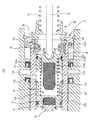
(第二の実施形態)
第二の実施形態のハイドロブースタ110について、第一の実施形態のハイドロブースタ10と異なる点について、図10を用いて説明する。なお、第一の実施形態のハイドロブースタ10と同じ構造の部分には、同じ番号を付してその説明を省略する。
(Second embodiment)
About the
図10に示すように、移動部材120が、フェイルシリンダ12の第二筒部12cの後部の内部に前後方向摺動可能に設けられている。移動部材120は、第一筒部120a、第二筒部120b、第一保持部120c、第二保持部120d、取付突起120eとから構成されている。
As shown in FIG. 10, the moving
第一筒部120aは円筒形状である。第二筒部120bは円筒形状であり、第一筒部120aの内側に第一筒部120aと同軸に形成されている。第一保持部120cは、リング状であり第一筒部120aと第二筒部120bの後部を接続して閉塞している。第二保持部120dは、第二筒部120bの先端を閉塞している。取付突起120eは、円柱形状であり、第二保持部120dの前面の中心から前方に突出形成されている。
The
第一筒部120aの外周面には、フェイルシリンダ12の第二筒部12cの内周面と全周に渡って接触するシール部材128が取り付けられている。取付突起120eは、円筒形状の第二シミュレータラバー124に挿通して、第二シミュレータラバー124を取り付けている。
A
第二筒部120bの内部に入力ピストン115が前後方向摺動可能に設けられている。入力ピストン115は、略円柱形状である。入力ピストン115の後端には、底部が円錐状に凹陥したロッド受け部115aが形成されている。ロッド受け部115aに、オペロッド16の押圧部16aが挿通して、オペロッド16が入力ピストン115の後端に連結している。
An
入力ピストン115の前端面には、保持凹部115bが凹陥形成されている。保持凹部115bには、円柱形状の第一シミュレータラバー123が挿通されて取り付けられている。第一シミュレータラバー123の先端は、入力ピストン115の前端面から前方に突出している。なお、第一シミュレータラバー123の先端は、移動部材120の第二保持部120dの後面から離間している。
A holding
入力ピストン115の外周面には、移動部材120の第二筒部120bの内周面と全周に渡って接触するシール部材129が取り付けられている。入力ピストン115の外周面には、段差状の保持面115cが形成されている。移動部材120の第二筒部120bの内部において、第二保持部120dの後面と保持面115cとの間に第一シミュレータスプリング121が設けられている。
A
保持ピストン33の底部33aと、移動部材120の第一保持部120cとの間には、第二シミュレータスプリング122が設けられている。第二シミュレータスプリング122のバネ定数は、第一シミュレータスプリング121のバネ定数よりも大きくなっている。第一シミュレータスプリング121と第二シミュレータスプリング122は、同軸に、前後方向同じ位置に設けられている。
A
ブレーキペダル71が踏まれると、第一シミュレータラバー123が移動部材120の第二保持部120dに当接するまで、ブレーキペダル71に作用する反力は、第一シミュレータスプリング121の発生荷重と、ペダルリターンスプリング27の発生荷重を合計した値となる。なお、保持ピストン33には、第二シミュレータスプリング122を介して、ブレーキペダル71からの操作力が伝達される。
When the
ブレーキペダル71に入力された操作力が回生制動力発生操作力P1(図5示)を超えると、上述したように回生制動力が発生する。そして、ブレーキペダル71に入力された操作力が摩擦制動力発生操作力P2(図5示)を超えると、「減圧モード」から「増圧モード」に移行して、上述したように摩擦制動力が発生する。
When the operation force input to the
第一シミュレータラバー123が移動部材120の第二保持部120dに当接し、第二シミュレータラバー124が保持ピストン33に当接するまでは、ブレーキペダル71に作用する反力は、ペダルリターンスプリング27による発生荷重と第二シミュレータスプリング122により発生した荷重の合計した値となる。つまり、第一シミュレータラバー123が移動部材120の第二保持部120dに当接するまでのブレーキペダル71に作用する反力よりも大きくなる。
The reaction force acting on the
第一シミュレータラバー123が移動部材120の第二保持部120dに当接してから、更にブレーキペダル71が踏まれると第一シミュレータラバー123が圧縮される。第一シミュレータラバー123は、その性質から、圧縮されるに従って徐々にバネ定数が上昇する。このため、第一シミュレータラバー123が移動部材120の第二保持部120dに当接する前後において、ブレーキペダル71のストローク当たりのブレーキペダル71に作用する反力が徐変し、前記反力の急変に伴う運転者の違和感が抑制される。
If the
第二シミュレータラバー124が保持ピストン33に当接すると、ブレーキペダル71に作用する反力は、ペダルリターンスプリング27、第二シミュレータスプリング122、第二シミュレータラバー124を並列接続した合成バネ定数に、ブレーキペダル71のストロークを乗算した値となる。つまり、第二シミュレータラバー124が保持ピストン33に当接するまでのブレーキペダル71に作用する反力よりも大きくなる。
When the
このように、ブレーキペダル71のストロークが増大するに従って、ブレーキペダル71に作用する反力が増大し、通常のブレーキ装置の操作感が再現されるようになっている。
In this way, as the stroke of the
第二の実施形態のハイドロブースタ110では、第一シミュレータスプリング121と第二シミュレータスプリング122は、前後方向同じ位置に設けられている。このため、ハイドロブースタ110の前後方向の寸法を削減することができる。
In the
(第三の実施形態)
第三の実施形態のハイドロブースタ210について、第一の実施形態のハイドロブースタ10と異なる点について、図11を用いて説明する。なお、第一の実施形態のハイドロブースタ10と同じ構造の部分には、同じ番号を付してその説明を省略する。
(Third embodiment)
About the
第二筒部120bの内部に入力ピストン215が前後方向摺動可能に設けられている。入力ピストン215は、外周面の断面形状が円形状のブロック状である。入力ピストン115の外周面には、フェイルシリンダ12の第二筒部12cの内周面と全周に渡って接触するシール部材225が取り付けられている。
An
入力ピストン215の後端には、底部が円錐状に凹陥したロッド受け部215aが形成されている。ロッド受け部215aに、オペロッド16の押圧部16aが挿通して、オペロッド16が入力ピストン215の後端に連結している。
At the rear end of the
入力ピストン215の前端面には、保持凹部215bが凹陥形成されている。保持凹部215bには、円柱形状のシミュレータラバー222が挿通されて取り付けられている。シミュレータラバー222の先端は、入力ピストン215の前端面から前方に突出している。なお、シミュレータラバー222の先端は、保持ピストン33の底部33aの後面から離間している。
A holding
入力ピストン215の前端面の保持凹部215bの外側には、円筒形状に凹陥した受け部215cが形成されている。保持ピストン33の底部33aと、受け部215cの間には、シミュレータスプリング221が設けられている。シミュレータスプリング221のバネ乗数は、シミュレータラバー222のバネ乗数よりも小さくなっている。
A receiving portion 215 c that is recessed in a cylindrical shape is formed outside the holding
ブレーキペダル71が踏まれると、シミュレータスプリング221が圧縮される。シミュレータラバー222が保持ピストン33に当接するまで、ブレーキペダル71に作用する反力は、ペダルリターンスプリング27の発生荷重とシミュレータスプリング221の発生荷重の合計した値となる。
When the
ブレーキペダル71に入力された操作力が回生制動力発生操作力P1(図5示)を超えると、上述したように回生制動力が発生する。そして、ブレーキペダル71に入力された操作力が摩擦制動力発生操作力P2(図5示)を超えると、「減圧モード」から「増圧モード」に移行して、上述したように摩擦制動力が発生する。
When the operation force input to the
シミュレータラバー222が保持ピストン33に当接すると、保持ピストン33に伝達されるブレーキペダル71からの操作力が急激に増大する。すると、「保持モード」から「増圧モード」に移行する。シミュレータラバー222が保持ピストン33に当接すると、ブレーキペダル71に作用する反力は、ペダルリターンスプリング27の発生荷重と、シミュレータスプリング221の発生荷重、シミュレータラバー222の発生荷重を合計した値となる。つまり、シミュレータラバー222が保持ピストン33に当接するまでのブレーキペダル71に作用する反力よりも大きくなる。
When the
シミュレータラバー222は、その性質から、圧縮されるに従って徐々にバネ定数が上昇する。このため、シミュレータラバー222が保持ピストン33に当接すると、ブレーキペダル71のストローク当たりのブレーキペダル71に作用する反力が徐々に増大する。このように、ブレーキペダル71のストロークが増大するに従って、ブレーキペダル71に作用する反力が増大し、通常のブレーキ装置の操作感が再現されるようになっている。
Due to the nature of the
なお、図11に示す例では、シミュレータラバー222は、円柱形状であるが、円筒形状であっても差し支え無い。
In the example illustrated in FIG. 11, the
(別の実施形態)
以上説明した実施形態では、ブレーキペダル71に入力される操作を検出するブレーキセンサ72は、ブレーキペダル71のストローク量を検出している。しかし、ブレーキセンサ72は、入力ピストン15や、連結部材31、オペロッド16のストローク量を検出するストロークセンサであっても差し支え無い。或いは、ブレーキセンサ72は、ブレーキペダル71や入力ピストン15や、連結部材31、オペロッド16に作用する操作力を検出する荷重センサであっても差し支え無い。
(Another embodiment)
In the embodiment described above, the
第一の実施形態のハイドロブースタ10において、移動部材32と保持ピストン33の間に、シミュレータスプリング26のバネ定数よりも小さいシミュレータスプリングが更に設けられている実施形態であっても差し支え無い。
In the
以上説明では、回生ブレーキ装置Aが搭載されているハイブリッド車両について本発明を説明した。しかし、移動部材32と保持ピストン33との距離と、スプールスプリング25の荷重とを調整する事で回生制動力が発生するストロークで「マスタ圧」が立ち上がるように設計する等により、回生ブレーキ装置Aが搭載されていない車両にも本発明の技術的思想が適用可能なこと、つまり、ハイドロブースタ10を用いることができることは言うまでもない。
In the above description, the present invention has been described for the hybrid vehicle on which the regenerative braking device A is mounted. However, by adjusting the distance between the moving
また、以上説明した実施形態では、入力ピストン15に運転者の操作力を伝達するブレーキ操作部材は、ブレーキペダル71である。しかし、ブレーキ操作部材は、ブレーキペダル71に限定されず、例えば、ブレーキレバーやブレーキハンドルであっても差し支え無い。そして、本実施形態の車両用制動装置(摩擦ブレーキユニットB)を、自動二輪車やその他車両に適用しても、本発明の技術的思想が適用可能なことは言うまでもない。
In the embodiment described above, the brake operation member that transmits the operation force of the driver to the
10…第一の実施形態のハイドロブースタ、11…マスタシリンダ、11f…第五ポート(供給ポート)、11h…第七ポート(リザーバ流路)、12…フェイルシリンダ、12f…第三インナーポート(減圧流路)、12g…第四インナーポート(リザーバ流路)、13…第一マスタピストン(マスタピストン)、14…第二マスタピストン(マスタピストン)、15…入力ピストン、19…リザーバ、23…スプールピストン(スプール弁)、23b…第三スプール凹部(増圧流路)、23c…第四スプール凹部(減圧流路、増圧流路)、23d…第一流通ポート(減圧流路)、23e…流通穴(減圧流路、増圧流路)、23f…第二流通ポート(増圧流路)、24…スプールシリンダ(スプール弁)、24c…スプールポート(増圧流路)、24d…第一スプール凹部(増圧流路)、24f…第二スプール凹部(減圧流路)、25…スプールスプリング、26…シミュレータスプリング(シミュレータ部材)、32…移動部材、33…保持ピストン、34…シミュレータラバー、36…フェイルスプリング、37…緩衝部材、53…調圧装置、61…アキュムレータ、71…ブレーキペダル(操作部材)、72…ブレーキセンサ、110…第二の実施形態のハイドロブースタ、115…入力ピストン、121…第一シミュレータスプリング(シミュレータ部材)、122…第二シミュレータスプリング(シミュレータ部材)、210…第三の実施形態のハイドロブースタ、221…シミュレータスプリング(シミュレータ部材)、222…シミュレータラバー(シミュレータ部材)、A…回生ブレーキ装置、B…摩擦ブレーキユニット
DESCRIPTION OF
Claims (7)
前記マスタシリンダの空間と接続され、ブレーキフルードの液圧を蓄圧するアキュムレータ(61)と、
前記マスタシリンダの空間と接続され、ブレーキフルードを貯留するリザーバ(19)と、
前記マスタシリンダの空間内に前後方向摺動可能に設けられ、車輪に摩擦制動力を付与する摩擦ブレーキ装置に供給されるブレーキフルードで満たされるマスタ室(10a、10b)を前方において前記マスタシリンダとの間で形成し、サーボ室(10c)を後方において前記マスタシリンダとの間で形成するマスタピストン(13、14)と、
前記マスタシリンダの空間内の前記マスタピストンの後方に設けられ、前記サーボ室と前記リザーバが連通する減圧モード、前記サーボ室と前記アキュムレータが連通する増圧モード、前記サーボ室が密閉される保持モードを切り替えるスプール弁(23、24)と、
前記マスタシリンダの後方に設けられ、運転者の操作力が伝達される操作部材(71)と、
前記マスタシリンダの空間内の前記スプール弁の後方に前後方向摺動可能に設けられ、前記操作部材と連結されて前記操作部材からの操作力が伝達され、前記操作力によって前記スプール弁を駆動する入力ピストン(15)と、
前記入力ピストンの前方において前記マスタシリンダの空間内に設けられ、前記入力ピストンを後方に付勢するシミュレータ部材(26)と、を有する車両用制動装置。 A master cylinder (11) having a columnar space (11p) in the front-rear direction;
An accumulator (61) connected to the space of the master cylinder and accumulating the fluid pressure of the brake fluid;
A reservoir (19) connected to the space of the master cylinder and storing brake fluid;
A master chamber (10a, 10b) which is provided in the space of the master cylinder so as to be slidable in the front-rear direction and is supplied to a friction brake device which applies a friction braking force to the wheels is filled with the master cylinder in front. A master piston (13, 14) that forms a servo chamber (10c) with the master cylinder in the rear;
A pressure reducing mode in which the servo chamber and the reservoir communicate with each other, a pressure increasing mode in which the servo chamber communicates with the accumulator, and a holding mode in which the servo chamber is sealed; Spool valves (23, 24) for switching between
An operating member (71) provided behind the master cylinder, to which the operating force of the driver is transmitted;
It is provided behind the spool valve in the space of the master cylinder so as to be slidable in the front-rear direction, and is connected to the operation member to transmit the operation force from the operation member, and drives the spool valve by the operation force. An input piston (15);
And a simulator member (26) provided in a space of the master cylinder in front of the input piston and biasing the input piston rearward.
前記ブレーキセンサが検出した前記操作部材に入力される操作に基づいて、車輪に回生制動力を付与する回生ブレーキ装置(A)と、
前記スプール弁の後方側に前記スプール弁と離間して、前記マスタシリンダの空間内に前後方向摺動可能に設けられた移動部材(32)を有し、
前記シミュレータ部材は、前記移動部材と前記入力ピストンとの間に設けられた請求項1に記載の車両用制動装置。 A brake sensor (72) for detecting an operation input to the operation member;
A regenerative braking device (A) for applying a regenerative braking force to a wheel based on an operation input to the operation member detected by the brake sensor;
A moving member (32) provided on the rear side of the spool valve, separated from the spool valve, and slidable in the front-rear direction in the space of the master cylinder;
The vehicle braking device according to claim 1, wherein the simulator member is provided between the moving member and the input piston.
前記フェイルシリンダを前記マスタシリンダに対して前方に付勢するフェイルスプリング(36)と、
前記入力ピストンは、前記フェイルシリンダ内に前後方向摺動可能に設けられ、
前記第一筒部の外周面に向けて開口し、前記アキュムレータからブレーキフルードが供給される供給ポート(11f)が前記マスタシリンダに形成され、
前記フェイルシリンダが摺動範囲の最後端に位置している状態において、前記リザーバと前記フェイルシリンダ内の前記入力ピストンの前方とに向けて開口し、前記リザーバと連通するリザーバ流路(11h、12g)が前記マスタシリンダ及び前記フェイルシリンダに形成され、
前記アキュムレータから前記ブレーキフルードが前記供給ポートに供給されている状態では、前記ブレーキフルードの圧力及び前記第一筒部と前記第二筒部の断面積差により発生する力によって、前記フェイルシリンダが前記マスタシリンダに対して後方に移動されて、前記フェイルシリンダが摺動範囲の最後端に位置され、
前記アキュムレータから前記ブレーキフルードが前記供給ポートに供給されていない状態では、前記フェイルスプリングの付勢力により前記フェイルシリンダが前記マスタシリンダに対して前方に移動され、前記リザーバ流路が遮断されて、前記フェイルシリンダ内の前記入力ピストンの前方の空間が密閉状態となり、前記入力ピストンに伝達された前記操作力によって、前記フェイルシリンダが前記マスタピストンを押圧可能となる請求項1〜請求項3のいずれか1項に記載の車両用制動装置。 It is provided behind the master piston in the space of the master cylinder so as to be slidable in the front-rear direction, and has an outer diameter larger than the outer diameter of the first cylinder part at the front and the first cylinder part at the front. A fail cylinder (12) formed with a second cylindrical portion;
A fail spring (36) for urging the fail cylinder forward with respect to the master cylinder;
The input piston is provided in the fail cylinder so as to be slidable in the front-rear direction,
A supply port (11f) that opens toward the outer peripheral surface of the first cylinder portion and is supplied with brake fluid from the accumulator is formed in the master cylinder,
In a state where the fail cylinder is located at the end of the sliding range, reservoir channels (11h, 12g) that open toward the reservoir and the front of the input piston in the fail cylinder and communicate with the reservoir. ) Is formed in the master cylinder and the fail cylinder,
In a state in which the brake fluid is supplied from the accumulator to the supply port, the fail cylinder is caused by the pressure generated by the pressure of the brake fluid and the cross-sectional area difference between the first cylinder part and the second cylinder part. Moved backward relative to the master cylinder, the fail cylinder is located at the end of the sliding range,
In a state where the brake fluid is not supplied from the accumulator to the supply port, the fail cylinder is moved forward with respect to the master cylinder by the biasing force of the fail spring, the reservoir flow path is shut off, The space ahead of the said input piston in a fail cylinder will be in a sealed state, and the said fail cylinder can press the said master piston by the said operating force transmitted to the said input piston. The vehicle braking device according to claim 1.
前記マスタピストンの後方において、前記マスタシリンダの空間内に固定された筒状のスプールシリンダ(24)と、
前記スプールシリンダの内部に前後方向に摺動可能に設けられたスプールピストン(23)と、から構成され、
前記スプールシリンダに対して前記スプールピストンを後方に付勢するスプールスプリング(25)を有し、
前記スプールピストンの摺動範囲の後方位置である減圧位置に前記スプールピストンが位置している状態において、前記サーボ室と前記リザーバを連通させる減圧流路(23c、23d、23e、24f)が前記スプールシリンダ及び前記スプールピストンの少なくとも一方に形成され、
前記スプールピストンの摺動範囲の前方位置である増圧位置に前記スプールピストンが位置している状態において、前記サーボ室と前記アキュムレータを連通させる増圧流路(23b、23c、23f、23e、24c、24d)が前記スプールシリンダ及び前記スプールピストンの少なくとも一方に形成され、
前記減圧位置と前記増圧位置の間の位置である保持位置に前記スプールピストンが位置している状態では、前記サーボ室と前記リザーバが遮断されるとともに、前記サーボ室と前記アキュムレータが遮断され、前記サーボ室が密閉されるように構成されている請求項1〜請求項4のいずれか1項に記載の車両用制動装置。 The spool valve is
A cylindrical spool cylinder (24) fixed in the space of the master cylinder behind the master piston;
A spool piston (23) provided inside the spool cylinder so as to be slidable in the front-rear direction,
A spool spring (25) for urging the spool piston rearward with respect to the spool cylinder;
In a state where the spool piston is located at a pressure reducing position which is a position behind the sliding range of the spool piston, a pressure reducing flow path (23c, 23d, 23e, 24f) for communicating the servo chamber and the reservoir is provided in the spool. Formed on at least one of the cylinder and the spool piston;
In the state where the spool piston is located at the pressure increasing position which is the front position of the sliding range of the spool piston, the pressure increasing flow paths (23b, 23c, 23f, 23e, 24c, and the like) for communicating the servo chamber and the accumulator 24d) is formed on at least one of the spool cylinder and the spool piston,
In a state where the spool piston is located at a holding position that is a position between the pressure reducing position and the pressure increasing position, the servo chamber and the reservoir are shut off, and the servo chamber and the accumulator are shut off, The vehicular braking apparatus according to any one of claims 1 to 4, wherein the servo chamber is configured to be sealed.
前記スプールピストンの後端面と前記保持ピストンとの間に設けられ、弾性を有する緩衝部材(37)と、を有する請求項5に記載の車両用制動装置。 A holding piston (33) provided in the space of the master cylinder and holding a rear end portion of the spool piston so as to be slidable in the front-rear direction;
The vehicle braking device according to claim 5, further comprising an elastic buffer member (37) provided between a rear end surface of the spool piston and the holding piston.
前記移動部材と前記保持ピストンとの当接部分には、シミュレータラバー(34)が取り付けられている請求項6に記載の車両用制動装置。 A moving member (32) provided on the rear side of the spool valve, separated from the spool valve, and slidable in the front-rear direction in the space of the master cylinder;
The vehicle braking device according to claim 6, wherein a simulator rubber (34) is attached to a contact portion between the moving member and the holding piston.
Priority Applications (4)
| Application Number | Priority Date | Filing Date | Title |
|---|---|---|---|
| JP2013137322A JP2015009698A (en) | 2013-06-28 | 2013-06-28 | Vehicular brake system |
| US14/314,483 US20150000266A1 (en) | 2013-06-28 | 2014-06-25 | Brake system for vehicle designed to improve mountability |
| DE102014212361.5A DE102014212361A1 (en) | 2013-06-28 | 2014-06-26 | BRAKING SYSTEM FOR A VEHICLE FOR IMPROVING ASSEMBLY SUITABILITY |
| CN201410302666.2A CN104249725A (en) | 2013-06-28 | 2014-06-27 | Brake system for vehicle designed to improve mountability |
Applications Claiming Priority (1)
| Application Number | Priority Date | Filing Date | Title |
|---|---|---|---|
| JP2013137322A JP2015009698A (en) | 2013-06-28 | 2013-06-28 | Vehicular brake system |
Publications (2)
| Publication Number | Publication Date |
|---|---|
| JP2015009698A true JP2015009698A (en) | 2015-01-19 |
| JP2015009698A5 JP2015009698A5 (en) | 2015-09-10 |
Family
ID=52017596
Family Applications (1)
| Application Number | Title | Priority Date | Filing Date |
|---|---|---|---|
| JP2013137322A Pending JP2015009698A (en) | 2013-06-28 | 2013-06-28 | Vehicular brake system |
Country Status (4)
| Country | Link |
|---|---|
| US (1) | US20150000266A1 (en) |
| JP (1) | JP2015009698A (en) |
| CN (1) | CN104249725A (en) |
| DE (1) | DE102014212361A1 (en) |
Families Citing this family (8)
| Publication number | Priority date | Publication date | Assignee | Title |
|---|---|---|---|---|
| JP2015009699A (en) * | 2013-06-28 | 2015-01-19 | 株式会社デンソー | Vehicular brake system |
| DE102016218421A1 (en) | 2016-09-26 | 2018-03-29 | Continental Teves Ag & Co. Ohg | Brake device for a hydraulic motor vehicle brake system |
| IT201700057996A1 (en) * | 2017-05-29 | 2018-11-29 | Freni Brembo Spa | INTEGRATED BRAKE PUMP FOR BRAKE BY WIRE BRAKE SYSTEM AND RELATIVE BRAKE BY WIRE BRAKE SYSTEM |
| CN107813806A (en) * | 2017-12-01 | 2018-03-20 | 浙江亚太机电股份有限公司上海分公司 | A kind of pressure release component and electro-hydraulic booster |
| CN108482352A (en) * | 2018-05-22 | 2018-09-04 | 浙江亚太机电股份有限公司上海分公司 | Hydraulic booster system |
| DE102018221941A1 (en) * | 2018-12-17 | 2020-06-18 | Continental Teves Ag & Co. Ohg | Brake device for a hydraulic motor vehicle brake system |
| JP7204502B2 (en) * | 2019-01-25 | 2023-01-16 | 株式会社アドヴィックス | Braking control device |
| IT201900025105A1 (en) * | 2019-12-20 | 2021-06-20 | Raicam Driveline S R L | Hydraulic brake distributor for two-wheeled vehicles |
Citations (2)
| Publication number | Priority date | Publication date | Assignee | Title |
|---|---|---|---|---|
| JP2005162134A (en) * | 2003-12-05 | 2005-06-23 | Nissin Kogyo Co Ltd | Vehicular brake device |
| JP2010524755A (en) * | 2007-04-19 | 2010-07-22 | コンチネンタル・テベス・アーゲー・ウント・コンパニー・オーハーゲー | Brake system for automobile |
Family Cites Families (7)
| Publication number | Priority date | Publication date | Assignee | Title |
|---|---|---|---|---|
| JP4333000B2 (en) * | 1999-12-10 | 2009-09-16 | トヨタ自動車株式会社 | Brake system for vehicles |
| JP4473751B2 (en) * | 2005-03-04 | 2010-06-02 | 本田技研工業株式会社 | Hydraulic brake device |
| US9354297B2 (en) | 2005-09-27 | 2016-05-31 | Qualcomm Incorporated | Position location using phase-adjusted transmitters |
| WO2009058916A2 (en) | 2007-10-29 | 2009-05-07 | Kelsey-Hayes Company | Hydraulic brake system with controlled boost |
| JP5817179B2 (en) * | 2011-03-30 | 2015-11-18 | 株式会社アドヴィックス | Hydraulic brake device |
| US8706358B2 (en) * | 2011-10-21 | 2014-04-22 | Honda Motor Co., Ltd. | Method of controlling braking in a vehicle |
| CN103158709A (en) * | 2011-12-15 | 2013-06-19 | 西安正昌电子有限责任公司 | Automobile brake system with energy recovery function |
-
2013
- 2013-06-28 JP JP2013137322A patent/JP2015009698A/en active Pending
-
2014
- 2014-06-25 US US14/314,483 patent/US20150000266A1/en not_active Abandoned
- 2014-06-26 DE DE102014212361.5A patent/DE102014212361A1/en not_active Withdrawn
- 2014-06-27 CN CN201410302666.2A patent/CN104249725A/en active Pending
Patent Citations (2)
| Publication number | Priority date | Publication date | Assignee | Title |
|---|---|---|---|---|
| JP2005162134A (en) * | 2003-12-05 | 2005-06-23 | Nissin Kogyo Co Ltd | Vehicular brake device |
| JP2010524755A (en) * | 2007-04-19 | 2010-07-22 | コンチネンタル・テベス・アーゲー・ウント・コンパニー・オーハーゲー | Brake system for automobile |
Also Published As
| Publication number | Publication date |
|---|---|
| CN104249725A (en) | 2014-12-31 |
| DE102014212361A1 (en) | 2014-12-31 |
| US20150000266A1 (en) | 2015-01-01 |
Similar Documents
| Publication | Publication Date | Title |
|---|---|---|
| JP5945250B2 (en) | Braking device for vehicle | |
| JP2015009698A (en) | Vehicular brake system | |
| JP6278236B2 (en) | Braking device for vehicle | |
| JP2015009705A (en) | Vehicular brake device | |
| US9388832B2 (en) | Master cylinder device and hydraulic brake system using the same | |
| JP6331418B2 (en) | Braking device for vehicle | |
| JP2015009704A (en) | Vehicular brake system | |
| US9238453B2 (en) | Master cylinder device | |
| US20110285199A1 (en) | Brake device | |
| JP2015009702A (en) | Vehicular brake device | |
| JP5626414B2 (en) | Master cylinder device and hydraulic brake system using the same | |
| JP2015009699A (en) | Vehicular brake system | |
| US9038380B2 (en) | Master cylinder device | |
| JP2015009701A (en) | Vehicular brake system | |
| WO2014072777A1 (en) | Master cylinder and master cylinder apparatus | |
| JP6354980B2 (en) | Braking device for vehicle | |
| JP2015202779A (en) | Vehicle brake device | |
| JP6300013B2 (en) | Braking device for vehicle | |
| JP6349835B2 (en) | Braking device for vehicle | |
| JP6307950B2 (en) | Braking device for vehicle | |
| JP2017047830A (en) | Vehicle brake device |
Legal Events
| Date | Code | Title | Description |
|---|---|---|---|
| A521 | Written amendment |
Free format text: JAPANESE INTERMEDIATE CODE: A523 Effective date: 20150722 |
|
| A621 | Written request for application examination |
Free format text: JAPANESE INTERMEDIATE CODE: A621 Effective date: 20150722 |
|
| A977 | Report on retrieval |
Free format text: JAPANESE INTERMEDIATE CODE: A971007 Effective date: 20160427 |
|
| A131 | Notification of reasons for refusal |
Free format text: JAPANESE INTERMEDIATE CODE: A131 Effective date: 20160510 |
|
| A02 | Decision of refusal |
Free format text: JAPANESE INTERMEDIATE CODE: A02 Effective date: 20161108 |