JP2015004584A - Sampling waveform measurement device and sampling waveform measurement method - Google Patents
Sampling waveform measurement device and sampling waveform measurement method Download PDFInfo
- Publication number
- JP2015004584A JP2015004584A JP2013129925A JP2013129925A JP2015004584A JP 2015004584 A JP2015004584 A JP 2015004584A JP 2013129925 A JP2013129925 A JP 2013129925A JP 2013129925 A JP2013129925 A JP 2013129925A JP 2015004584 A JP2015004584 A JP 2015004584A
- Authority
- JP
- Japan
- Prior art keywords
- frequency
- sampling
- phase
- unit
- value
- Prior art date
- Legal status (The legal status is an assumption and is not a legal conclusion. Google has not performed a legal analysis and makes no representation as to the accuracy of the status listed.)
- Granted
Links
Images


Landscapes
- Photometry And Measurement Of Optical Pulse Characteristics (AREA)
Abstract
Description
本発明は、高速な被測定信号の波形を測定する技術に関し、特に被測定信号のビットレートと非同期にサンプリングして得られたサンプル値の信号列から同期した被測定信号の波形を得ることができるソフトウエア同期法を用いた波形測定技術において、連続したサンプル値に対して連続して同期をかけることができるようにするための技術に関する。 The present invention relates to a technique for measuring a waveform of a signal under measurement at high speed, and in particular, can obtain a waveform of a signal under measurement synchronized with a signal sequence of sample values obtained by sampling asynchronously with the bit rate of the signal under measurement. The present invention relates to a technique for enabling continuous synchronization of continuous sample values in a waveform measurement technique using a software synchronization method.
高速な被測定信号の波形を測定する方法として、等価サンプリング法による波形測定が広く用いられている。 As a method for measuring the waveform of a signal under measurement at high speed, waveform measurement by an equivalent sampling method is widely used.
等価サンプリング方式は、図13の(a)のような一定周期で同じ波形が繰り返される被測定信号Sinに対し、図13の(b)のように、被測定信号Sinの波形の繰り返し周期の整数倍に対してして時間差Δtをもつ周期のサンプリング用パルスPs(i)を与える方式で、これによって得られるサンプル値y(i)のエンベロープが、図13の(c)の破線で示すように、被測定信号Sinの時間軸が拡大された波形となり、低速のA/D変換器でエンベロープ波形を測定することが出来る。また、被測定信号Sinが、一定のビットレートで変調された変調信号の場合にはそのアイパターンを測定することができる。 The equivalent sampling method is an integer of the repetition period of the waveform of the signal under test Sin as shown in FIG. 13B with respect to the signal under test Sin where the same waveform is repeated at a constant period as shown in FIG. In this method, a sampling pulse Ps (i) having a period having a time difference Δt with respect to the double is obtained, and the envelope of the sample value y (i) obtained thereby is shown by a broken line in FIG. The waveform of the signal under test Sin is expanded, and the envelope waveform can be measured with a low-speed A / D converter. Further, when the signal under test Sin is a modulated signal modulated at a constant bit rate, the eye pattern can be measured.
ここで、被測定信号の繰返し周波数またはビットレートをfin、サンプリング用パルスの繰返し周波数(サンプリング周波数)をfs とすると、時間差Δtは次式で表される。 Here, if the repetition frequency or bit rate of the signal under measurement is fin and the repetition frequency (sampling frequency) of the sampling pulse is fs, the time difference Δt is expressed by the following equation.
Δt=1/fs −N/fin ……(1′)
ここで、Nは整数である。
Δt = 1 / fs−N / fin (1 ′)
Here, N is an integer.
この等価サンプリング方式では、被測定信号の繰返し周波数またはビットレート(以下ビットレートと略す)と同期してサンプリングする必要があるため、被測定信号のビットレートと同期したトリガ信号を別途入力するか、あるいはビットレートに対応したクロック信号を被測定信号から抽出するクロック再生回路が必要であった。 In this equivalent sampling method, since it is necessary to sample in synchronization with the repetition frequency or bit rate of the signal under measurement (hereinafter abbreviated as bit rate), a trigger signal synchronized with the bit rate of the signal under measurement is input separately, Alternatively, a clock recovery circuit that extracts a clock signal corresponding to the bit rate from the signal under measurement is required.
しかし、長距離伝送後の信号を測定する場合にはトリガ信号を用意することが困難であり、またクロック再生回路は広範囲のビットレートに対応することが難しいという問題があった。 However, when measuring a signal after long-distance transmission, it is difficult to prepare a trigger signal, and the clock recovery circuit has a problem that it is difficult to cope with a wide range of bit rates.
この問題を解決する技術として、被測定信号のビットレートと非同期でサンプリングされた信号から同期した被測定信号の波形(アイパターン)が得られるソフトウエア同期法が提案されている。 As a technique for solving this problem, a software synchronization method has been proposed in which a waveform (eye pattern) of a signal under measurement synchronized with a signal sampled asynchronously with the bit rate of the signal under measurement is obtained.
図14に、従来のソフトウエア同期方式を用いたサンプリング波形測定装置の構成を示す。 FIG. 14 shows a configuration of a sampling waveform measuring apparatus using a conventional software synchronization method.
この装置では、被測定信号Sinはサンプリング部11に入力され、被測定信号Sinのビットレートと非同期の一定のサンプリング周波数fs でサンプリングされる。 In this apparatus, the signal under test Sin is input to the sampling unit 11 and sampled at a constant sampling frequency fs that is asynchronous with the bit rate of the signal under test Sin.
サンプリング部11でサンプリングされた被測定信号Sin(i)はA/D変換部12でデジタルのサンプル値y(i)に変換される。 The signal under test Sin (i) sampled by the sampling unit 11 is converted into a digital sample value y (i) by the A / D conversion unit 12.
図15の(a)に示すように、被測定信号Sinにはビットレートfinとその高調波(2fin、3fin、…)の周波数成分があり、同図(b)のようにサンプリング用パルスPs(i)には、サンプリング周波数fs とその高調波(2fs 、3fs 、…)の周波数成分があり、それらを同図(c)のように周波数軸上に重ねると、被測定信号のビットレートとサンプリング周波数の高調波との間のビート(基本ビート周波数fb )と、被測定信号のビットレートの高調波とサンプリング周波数の高調波との間のビート(高調波ビート周波数2fb 、3fb 、…)が生じる。 As shown in FIG. 15 (a), the signal under test Sin has a frequency component of the bit rate fin and its harmonics (2fin, 3fin,...), And the sampling pulse Ps ( i) has a sampling frequency fs and frequency components of its harmonics (2fs, 3fs,...), and when these are superimposed on the frequency axis as shown in FIG. A beat between the harmonics of the frequency (basic beat frequency fb) and a beat between the harmonics of the bit rate of the signal under measurement and the harmonics of the sampling frequency (harmonic beat frequencies 2fb, 3fb,...) Are generated. .
図15(c)より、基本ビート周波数fb は次式で表される。
fb =fin−Nfs ……(2′)
From FIG. 15C, the basic beat frequency fb is expressed by the following equation.
fb = fin-Nfs (2 ')
また、式(1′)と式(2′)より、
fb=fin・fs ・Δt=fin/S ……(3′)
となる。ここで、Sはサンプリング周期をΔtで除した値であり、サンプリングによる時間軸拡大の倍率を表している。式(3′)より、基本ビート周波数fb はサンプル値y(i)の繰返し周波数に等しいことが分かる。
Also, from Equation (1 ') and Equation (2')
fb = fin · fs · Δt = fin / S (3 ′)
It becomes. Here, S is a value obtained by dividing the sampling period by Δt, and represents the magnification of the time axis expansion by sampling. From equation (3 '), it can be seen that the basic beat frequency fb is equal to the repetition frequency of the sample value y (i).
したがって、サンプル値y(i)の信号列には、同図の(d)のように、各ビート成分が含まれることになる。また、ビットレートとサンプリング周波数の関係により、同図の(e)のように、ビート周波数がfs /2で折り返される場合もある。 Therefore, each signal component of the sample value y (i) includes each beat component as shown in FIG. Depending on the relationship between the bit rate and the sampling frequency, the beat frequency may be folded back at fs / 2 as shown in FIG.
このサンプル値の信号列から基本ビート周波数fb と位相を検出することができれば、サンプル値が被測定信号の周期内のどの時間位置でサンプリングされたものかを特定することができる。 If the basic beat frequency fb and the phase can be detected from the signal sequence of the sample values, it is possible to specify at which time position the sample values are sampled within the period of the signal under measurement.
具体的には、式(3′)より、時間差Δtは、
Δt=fb /(fin・fs ) ……(4′)
より求められ、サンプル値y(i)に対応する時間軸値X(i)は、
X(i)={i・Δt+(π+φ)/(2πfin)}mod(1/fin)
……(5′)
より求めることができる。ここで、X(i)は秒単位の時間軸値であり、φは基本ビート周波数成分の位相である。
Specifically, from the equation (3 ′), the time difference Δt is
Δt = fb / (fin · fs) (4 ')
And the time axis value X (i) corresponding to the sample value y (i) is
X (i) = {i · Δt + (π + φ) / (2πfin)} mod (1 / fin)
...... (5 ')
It can be obtained more. Here, X (i) is a time axis value in seconds, and φ is the phase of the basic beat frequency component.
式(5′)の右辺第1項のi・Δtは、i番目のサンプリング時刻を秒単位の時刻に変換する演算である。また、式(5′)の右辺第2項のφ/(2πfin)の項は、ラジアン単位の位相φを秒単位の時刻に変換する演算であり、φが変わっても表示される波形の位相(例えばアイ開口の位置)を一定に保つためのものである。また、式(5′)の右辺第2項のπ/(2πfin)の項は、波形の横軸方向の表示位置(例えばアイ開口の位置)を決めるオフセット値であり、この値に限られるものではない。mod は剰余演算であり、式(5′)のmod(1/fin)の演算によって時間軸値X(i)は被測定信号の1ビット周期で折り返され、被測定信号のビット周期内の時間位置に変換される。 I · Δt in the first term on the right side of the equation (5 ′) is an operation for converting the i-th sampling time into a time in seconds. The term φ / (2πfin) in the second term on the right side of the equation (5 ′) is an operation for converting the phase φ in radians into the time in seconds, and the phase of the waveform displayed even when φ changes. (For example, the position of the eye opening) is kept constant. Also, the second term of π / (2πfin) on the right side of the equation (5 ′) is an offset value that determines the display position of the waveform in the horizontal axis direction (for example, the position of the eye opening), and is limited to this value. is not. mod is a remainder operation, and the time axis value X (i) is turned back in the 1-bit period of the signal under measurement by the operation of mod (1 / fin) in equation (5 ′), and the time within the bit period of the signal under measurement Converted to position.
したがって、横軸を時間軸値X(i)、縦軸をサンプル値y(i)として2次元平面上に特定個数の点をプロットすると、同期のとれた被測定信号の波形(アイパターン)が得られる。 Therefore, when a specific number of points are plotted on a two-dimensional plane with the horizontal axis as the time axis value X (i) and the vertical axis as the sample value y (i), the waveform (eye pattern) of the signal under measurement in synchronization is obtained. can get.
この処理を行なうために、ソフトウエア同期部13は、特定個数のサンプル値y(i)を用いて以下の処理を実行する。 In order to perform this process, the software synchronization unit 13 executes the following process using a specific number of sample values y (i).
即ち、連続して取得された複数のサンプル値y(i)を離散フーリエ変換部14により離散フーリエ変換して離散スペクトルPiを求め、補間処理部15に出力する。補間処理部15は離散スペクトルPiを補間した補間値P(f)をビート周波数検出部16に出力する。
That is, the discrete Fourier
ビート周波数検出部16は、スペクトルの極大値が高調波ビート周波数またはその折り返しと一致し、補間値P(f)が極大となる基本ビート周波数fb を検出して、位相検波部17および時間軸算出部18に出力する。 The beat frequency detection unit 16 detects the basic beat frequency fb at which the maximum value of the spectrum coincides with the harmonic beat frequency or its aliasing, and the interpolation value P (f) is maximum, and the phase detection unit 17 and the time axis calculation To the unit 18.
位相検波部17は基本ビート周波数fb の成分におけるy(i)の位相φを検出する。 The phase detector 17 detects the phase φ of y (i) in the component of the basic beat frequency fb.
時間軸検出部18は、次式(1)よりUI(ユニットインターバル)単位の時間軸値x(i)を求める。 The time axis detector 18 obtains a time axis value x (i) in units of UI (unit interval) from the following equation (1).
x(i)=[(i・fb /fs )+(π+φ)/2π]mod 1 ……(1)
ここで、記号mod は剰余演算を表す。
x (i) = [(i · fb / fs) + (π + φ) / 2π] mod 1 (1)
Here, the symbol mod represents a remainder operation.
式(1)は、前式(5′)の秒単位の時間軸値X(i)を1/finで除算してUI単位の時間軸値x(i)に変換したものである。サンプル値y(i)の離散フーリエ変換を行なう際に、サンプリング周波数を1に規格化することにより、基本ビート周波数はサンプリング周波数fs に対する相対周波数fb /fs として求まる。式(1)には、被測定信号のビットレートfinが含まれておらず、基本ビート周波数fb はサンプリング周波数fs に対する相対周波数で表されているため、サンプリング周波数fs およびビットレートfinが未知であっても、UI単位の時間軸値x(i)を求めることが出来る。 Equation (1) is obtained by dividing the time axis value X (i) in seconds in the previous equation (5 ′) by 1 / fin to convert it into a time axis value x (i) in UI units. When the discrete Fourier transform of the sample value y (i) is performed, the basic beat frequency is obtained as a relative frequency fb / fs with respect to the sampling frequency fs by normalizing the sampling frequency to 1. Equation (1) does not include the bit rate fin of the signal under measurement, and the basic beat frequency fb is expressed as a relative frequency with respect to the sampling frequency fs, so that the sampling frequency fs and the bit rate fin are unknown. Even in this case, the time axis value x (i) in UI units can be obtained.
このようにして得られた時間軸x(i)は、サンプル値y(i)とともに波形表示部19に出力される。波形表示部19は、縦軸をサンプル値y(i)、横軸を時間軸値x(i)として2次元平面上に特定個数の点をプロットすることで、被測定信号の波形を描画する。
The time axis x (i) obtained in this way is output to the
以上により、サンプリング周波数fs およびビットレートfinが未知であっても、同期のとれた被測定信号の波形(アイパターン)が得られ、その時間軸値はUI単位となる。 As described above, even if the sampling frequency fs and the bit rate fin are unknown, a synchronized waveform (eye pattern) of the signal under measurement is obtained, and the time axis value is in UI units.
上記のようなソフトウエア同期法を用いたサンプリング波形測定装置の例は、例えば特許文献1に開示されている。
An example of a sampling waveform measuring apparatus using the software synchronization method as described above is disclosed in
上記した従来のソフトウエア同期法は、特定個数のサンプル値y(i)に対して得られたビート周波数と位相の情報からサンプル値毎の時間軸値を生成するという同期処理を行なうものであり、連続したサンプル値に対して継続的に同期処理をかけることはできなかった。このため、連続したサンプル値に対しては、特定個数のサンプル値毎に同期処理を繰返し行なうことになり、各同期処理の間で時間軸が僅かに不連続になるという問題があった。 The above-described conventional software synchronization method performs a synchronization process of generating a time axis value for each sample value from beat frequency and phase information obtained for a specific number of sample values y (i). However, it was not possible to continuously apply synchronization processing to consecutive sample values. For this reason, for continuous sample values, the synchronization process is repeated for each specific number of sample values, and there is a problem that the time axis becomes slightly discontinuous between the synchronization processes.
また、被測定信号のタイミングジッタに追従可能な周波数帯域を任意に設定できないため、指定された周波数帯域でのタイミングジッタの評価ができないという問題もあった。 In addition, since it is not possible to arbitrarily set a frequency band that can follow the timing jitter of the signal under measurement, there is also a problem that the timing jitter cannot be evaluated in the designated frequency band.
本発明は、上記問題を解決し、連続したサンプル値に対して継続的に同期をかけることができ、被測定信号のタイミングジッタに追従可能な周波数帯域を任意に設定できるサンプリング波形測定装置および方法を提供することを目的としている。 The present invention solves the above-described problems, and can continuously synchronize a continuous sample value, and a sampling waveform measuring apparatus and method capable of arbitrarily setting a frequency band capable of following the timing jitter of a signal under measurement. The purpose is to provide.
前記目的を達成するために、本発明の請求項1のサンプリング波形測定装置は、
被測定信号をサンプリング周波数でサンプリングするサンプリング部(21)と、
前記サンプリング部でサンプリングされた被測定信号をデジタルのサンプル値の信号列に変換するA/D変換部(22)と、
前記サンプル値の信号列から前記被測定信号の繰返し周波数またはビットレートと前記サンプリング周波数の整数倍との間のビート周波数を初期ビート周波数(fb0)として出力するソフトウエア同期部(23)と、
前記ソフトウエア同期部から出力された前記初期ビート周波数を初期周波数として正弦波を出力する数値制御発振器(26)、該数値制御発振器から出力される正弦波と前記サンプル値の信号列とを乗算する乗算器(27)、該乗算器の出力信号の低周波成分を出力する低域通過フィルタ(28)、該低域通過フィルタが出力する前記低周波成分の位相を出力する位相検波器(29)および該位相検波器が出力する位相に応じて前記数値制御発振器の周波数を帰還制御する帰還手段(30)とからなる位相ロックループ部(25)と、
前記数値制御発振器の周波数と前記位相検波器が出力する位相から、前記サンプル値それぞれの時間軸値を算出する時間軸算出部(40)とを備え、
前記時間軸算出部で算出された時間軸値と前記サンプル値から前記被測定信号の波形を得ることを特徴としている。
In order to achieve the above object, a sampling waveform measuring apparatus according to
A sampling section (21) for sampling the signal under measurement at a sampling frequency;
An A / D converter (22) for converting the signal under measurement sampled by the sampling unit into a signal sequence of digital sample values;
A software synchronizer (23) for outputting a beat frequency between the repetition frequency or bit rate of the signal under measurement and an integer multiple of the sampling frequency as an initial beat frequency (fb 0 ) from the signal sequence of the sample values;
A numerically controlled oscillator (26) that outputs a sine wave with the initial beat frequency output from the software synchronization unit as an initial frequency, and multiplies the sine wave output from the numerically controlled oscillator by the signal sequence of the sample value. A multiplier (27), a low-pass filter (28) that outputs a low-frequency component of the output signal of the multiplier, and a phase detector (29) that outputs the phase of the low-frequency component output by the low-pass filter And a phase lock loop section (25) comprising feedback means (30) for feedback controlling the frequency of the numerically controlled oscillator according to the phase output by the phase detector,
A time axis calculation unit (40) for calculating a time axis value of each of the sample values from the frequency of the numerically controlled oscillator and the phase output by the phase detector;
The waveform of the signal under measurement is obtained from the time axis value calculated by the time axis calculation unit and the sample value.
また、本発明の請求項2のサンプリング波形測定装置は、請求項1記載のサンプリング波形測定装置において、
前記A/D変換部から出力されるサンプル値の信号列に対して非線形処理を行なう非線形処理部(32)を設け、
前記ソフトウエア同期部および前記位相ロックループ部の前記乗算器に対して、前記サンプル値の代わりに前記非線形処理部の出力を与えることを特徴とする。
A sampling waveform measuring apparatus according to
A non-linear processing unit (32) for performing non-linear processing on a signal sequence of sample values output from the A / D conversion unit;
The multiplier of the software synchronization unit and the phase locked loop unit is provided with an output of the nonlinear processing unit instead of the sample value.
また、本発明の請求項3のサンプリング波形測定装置は、請求項1または請求項2記載のサンプリング波形測定装置において、
前記ソフトウエア同期部が、前記サンプル値または前記非線形処理部の出力の前記初期ビート周波数の成分の位相を初期位相(φ0)として出力し、
該初期位相に応じて前記位相ロックループ部の前記数値制御発振器の位相の初期値が設定されることを特徴とする。
The sampling waveform measuring device according to
The software synchronization unit outputs the phase of the initial beat frequency component of the sample value or the output of the nonlinear processing unit as an initial phase (φ 0 ),
The initial value of the phase of the numerically controlled oscillator of the phase lock loop unit is set according to the initial phase.
また、本発明の請求項4のサンプリング波形測定装置は、請求項1〜3のいずれかに記載のサンプリング波形測定装置において、
前記ソフトウエア同期部が、前記サンプル値または前記非線形処理部の出力の前記初期ビート周波数の成分の振幅を初期振幅(a0)として出力し、
該初期振幅に応じて前記位相ロックループ部の前記低域通過フィルタの振幅の初期値が設定されることを特徴とする。
Moreover, the sampling waveform measuring device of
The software synchronization unit outputs the amplitude of the component of the initial beat frequency of the sample value or the output of the nonlinear processing unit as an initial amplitude (a 0 ),
The initial value of the amplitude of the low-pass filter of the phase-locked loop unit is set according to the initial amplitude.
また、本発明の請求項5のサンプリング波形測定装置は、請求項1〜4のいずれかに記載のサンプリング波形測定装置において、
前記位相検波器が出力する位相に対する前記帰還手段の帰還係数および前記低域通過フィルタの遮断周波数の少なくとも一方を可変することで、前記位相ロックループ部の閉ループ帯域を可変する閉ループ帯域可変手段(33)を有していることを特徴とする。
Moreover, the sampling waveform measuring device of
Closed-loop band varying means (33) for varying the closed-loop band of the phase-locked loop section by varying at least one of the feedback coefficient of the feedback means and the cutoff frequency of the low-pass filter with respect to the phase output by the phase detector. ).
また、本発明の請求項6のサンプリング波形測定装置は、請求項1〜5のいずれかに記載のサンプリング波形測定装置において、
前記位相ロックループ部の同期外れを検出する同期外れ検出手段(34)を有し、
該同期外れ検出手段によって同期外れが検出された場合に、前記ソフトウエア同期部によるソフトウエア同期処理に戻り、前記位相ロックループ部の同期を回復させることを特徴とする。
Moreover, the sampling waveform measuring device of
An out-of-synchronization detecting means (34) for detecting out-of-synchronization of the phase lock loop unit;
When out-of-synchronization is detected by the out-of-synchronization detecting means, the process returns to the software synchronization processing by the software synchronization unit, and the synchronization of the phase lock loop unit is recovered.
また、本発明の請求項7のサンプリング波形測定装置は、請求項1〜6のいずれかに記載のサンプリング波形測定装置において、
前記時間軸算出部で算出された複数の時間軸値から、所定の時間軸値範囲内に前記時間軸値が存在しない欠落領域の有無を検出する欠落検出手段(35)を有し、
該欠落検出手段によって欠落が検出された場合に、前記サンプリング部における前記サンプリング周波数を変更するとともに、前記ソフトウエア同期部による同期処理を実行させることで、前記時間軸値の欠落状態から復帰させることを特徴とする。
Moreover, the sampling waveform measuring device of
From a plurality of time axis values calculated by the time axis calculation unit, having a missing detection means (35) for detecting the presence or absence of a missing region where the time axis value does not exist within a predetermined time axis value range,
When missing is detected by the missing detection means, the sampling frequency in the sampling unit is changed, and the synchronization process by the software synchronization unit is executed to recover from the time axis value missing state. It is characterized by.
また、本発明の請求項8のサンプリング波形測定装置は、請求項1〜7のいずれかに記載のサンプリング波形測定装置において、
前記ソフトウエア同期部は、
前記サンプル値または前記非線形処理部の出力を離散フーリエ変換して離散スペクトルを算出し、該離散スペクトルの強度が最大となる周波数を前記初期ビート周波数として検出することを特徴とする。
Moreover, the sampling waveform measuring device of
The software synchronization unit is
A discrete spectrum is calculated by performing a discrete Fourier transform on the sample value or the output of the nonlinear processing unit, and a frequency at which the intensity of the discrete spectrum is maximized is detected as the initial beat frequency.
また、本発明の請求項9のサンプリング波形測定装置は、請求項1〜7のいずれかに記載のサンプリング波形測定装置において、
前記ソフトウエア同期部は、
前記サンプル値または前記非線形処理部の出力を離散フーリエ変換して離散スペクトルを算出し、該離散スペクトルの強度が極大となる複数の極大周波数を、前記被測定信号の繰返し周波数またはビットレートと前記サンプリング周波数の整数倍との間で生じる基本ビート周波数の候補値として検出し、該候補値のうち、前記被測定信号の繰返し周波数またはビットレートの整数倍と前記サンプリング周波数の整数倍との間で生じる高調波ビート周波数と前記極大周波数との誤差が最も小さくなる候補値を、前記初期ビート周波数と決定して出力することを特徴とする。
Moreover, the sampling waveform measuring device of
The software synchronization unit is
A discrete spectrum is calculated by performing discrete Fourier transform on the sample value or the output of the non-linear processing unit, and a plurality of maximum frequencies at which the intensity of the discrete spectrum is maximized are determined as the repetition frequency or bit rate of the signal under measurement and the sampling. Detected as a candidate value of a basic beat frequency that occurs between an integer multiple of the frequency, and occurs between an integer multiple of the repetition frequency or bit rate of the signal under measurement and the integer multiple of the sampling frequency among the candidate values A candidate value that minimizes an error between a harmonic beat frequency and the maximum frequency is determined as the initial beat frequency and is output.
また、本発明の請求項10のサンプリング波形測定方法は、
被測定信号をサンプリング周波数でサンプリングし、該サンプリングした被測定信号をデジタルのサンプル値の信号列に変換する段階と、
前記サンプル値の信号列から前記被測定信号の繰返し周波数またはビットレートと前記サンプリング周波数の整数倍との間のビート周波数を初期ビート周波数(fb0)として出力する段階と、
前記初期ビート周波数を初期周波数として発生した正弦波と、前記サンプル値の信号列とを乗算し、該乗算結果から低周波成分を抽出し、該抽出した低周波成分の位相を検出し、該検出した位相で前記正弦波の周波数を帰還制御する段階と、
前記正弦波の周波数と前記検出した位相から、前記サンプル値それぞれの時間軸値を算出する段階とを含み、
前記算出した時間軸値と前記サンプル値から前記被測定信号の波形を得ることを特徴としている。
Moreover, the sampling waveform measuring method according to claim 10 of the present invention comprises:
Sampling the signal under measurement at a sampling frequency, and converting the sampled signal under measurement into a signal sequence of digital sample values;
Outputting a beat frequency between the repetition frequency or bit rate of the signal under measurement and an integer multiple of the sampling frequency as an initial beat frequency (fb 0 ) from the signal sequence of the sample values;
Multiplying the sine wave generated with the initial beat frequency as the initial frequency and the signal sequence of the sample value, extracting a low frequency component from the multiplication result, detecting the phase of the extracted low frequency component, and detecting the phase Feedback control of the frequency of the sine wave with the adjusted phase;
Calculating a time axis value of each of the sample values from the frequency of the sine wave and the detected phase,
The waveform of the signal under measurement is obtained from the calculated time axis value and the sample value.
このように、本発明のサンプリング波形測定装置では、ソフトウエア同期処理で得られたビート周波数を初期周波数とする正弦波を発生してサンプル値に乗算し、その乗算結果の低周波成分に対して位相検波を行い、検出した位相で正弦波の周波数に帰還制御をかけることで、被測定信号に対する同期を維持している。 As described above, in the sampling waveform measuring apparatus of the present invention, a sine wave having the beat frequency obtained by the software synchronization processing as an initial frequency is generated and multiplied by the sample value, and the low frequency component of the multiplication result is obtained. By performing phase detection and applying feedback control to the frequency of the sine wave with the detected phase, synchronization with the signal under measurement is maintained.
このため、ソフトウエア同期処理を繰り返すことなく、連続したサンプル値に対して継続的に同期処理をかけることができ、各ソフトウエア同期処理を繰り返すことによる時間軸の不連続を発生させずに済む。 For this reason, it is possible to continuously apply synchronization processing to consecutive sample values without repeating software synchronization processing, and it is not necessary to cause time axis discontinuity due to repetition of each software synchronization processing. .
また、サンプル値に対して非線形処理を行い、ソフトウエア同期部と位相ロックループ部に与える構成では、被測定信号がNRZ形式で入力された場合でも対応できる。 In addition, the configuration in which nonlinear processing is performed on the sample value and given to the software synchronization unit and the phase lock loop unit can cope with the case where the signal under measurement is input in the NRZ format.
また、ソフトウエア同期部が、初期ビート周波数の成分の位相と振幅の少なくとも一方を算出する機能を有していて、その位相あるいは振幅を位相ロックループ部の数値制御発振器あるいは低域通過フィルタに初期設定する機能を有している場合には、位相ロックループの収束が速くなり、速やかに波形の取得を開始できる。 In addition, the software synchronization unit has a function of calculating at least one of the phase and amplitude of the component of the initial beat frequency, and the phase or amplitude is initially transmitted to the numerically controlled oscillator or low-pass filter of the phase lock loop unit. When the setting function is provided, the convergence of the phase lock loop becomes faster, and waveform acquisition can be started quickly.
また、位相ロックループ部の閉ループ帯域を可変する閉ループ帯域可変手段(33)を有している場合、所望の帯域におけるタイミングジッタの評価が容易に行なえる。 In addition, in the case where the closed-loop bandwidth varying means (33) for varying the closed-loop bandwidth of the phase lock loop section is provided, the timing jitter in the desired bandwidth can be easily evaluated.
また、位相ロックループ部の同期外れを検出する同期外れ検出手段(34)や、時間軸値の欠落の発生を検出する欠落検出手段(35)を有していれば、同期外れや時間軸値の欠落状態から容易に復帰させることができる。 Further, if it has out-of-synchronization detection means (34) for detecting out-of-synchronization of the phase lock loop section and missing detection means (35) for detecting occurrence of time-axis value loss, out-of-synchronization and time-axis value It is possible to easily recover from the missing state.
また、ソフトウエア同期部を、サンプル値または前記非線形処理部の出力を離散フーリエ変換して離散スペクトルを算出し、その離散スペクトルの強度が最大となる周波数を前記初期ビート周波数として検出する構成、あるいは、離散スペクトルの強度が極大となる複数の極大周波数を、被測定信号の繰返し周波数またはビットレートと前記サンプリング周波数の整数倍との間で生じる基本ビート周波数の候補値として検出し、それら候補値のうち、被測定信号の繰返し周波数またはビットレートの整数倍とサンプリング周波数の整数倍との間で生じる高調波ビート周波数と前記極大周波数との誤差が最も小さくなる候補値を、初期ビート周波数と決定して出力する構成であれば、精度は低くても高速に初期ビート周波数を求めることができる。 Further, the software synchronization unit calculates a discrete spectrum by performing a discrete Fourier transform on the sample value or the output of the nonlinear processing unit, and detects a frequency at which the intensity of the discrete spectrum is maximum as the initial beat frequency, or Detecting a plurality of maximum frequencies at which the intensity of the discrete spectrum becomes maximum as candidate values of basic beat frequencies generated between the repetition frequency or bit rate of the signal under measurement and an integer multiple of the sampling frequency, Among them, the initial beat frequency is determined as a candidate value that minimizes the error between the harmonic beat frequency generated between the repetition frequency or bit rate of the signal under measurement and an integer multiple of the sampling frequency and the maximum frequency. The initial beat frequency can be obtained at high speed even with low accuracy. .
以下、図面に基づいて本発明の実施の形態を説明する。
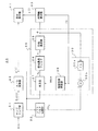
図1は、本発明を適用したサンプリング波形測定装置20の基本構成を示している。
Hereinafter, embodiments of the present invention will be described with reference to the drawings.
FIG. 1 shows a basic configuration of a sampling
このサンプリング波形測定装置20のサンプリング部21に入力される被測定信号Sinの繰り返し周波数またはビットレート(以下、これらを含めてビットレートと記す)を、finとする。
The repetition frequency or bit rate of the signal under test Sin input to the
サンプリング部21は、ビットレートfin と非同期の一定のサンプリング周波数fs で被測定信号Sinをサンプリングする。サンプリングされた被測定信号Sin(i)は、A/D変換部22でデジタルのサンプル値y(i)に変換される。ここでiは、サンプリングされた順番を示す整数である。
The
なお、図示しないが、サンプリング部21は、サンプリング周波数fs のサンプリングパルスを発生するパルス発生器と、サンプリングパルスが入力された時に被測定信号Sinをサンプリングするサンプリングヘッドからなる。被測定信号Sinが電気信号でサンプリングパルスが電気パルスの場合、被測定信号Sinが光信号でサンプリングパルスが電気パルスの場合、被測定信号Sinが電気信号でサンプリングパルスが光パルスの場合、被測定信号Sinが光信号でサンプリングパルスが光パルスの場合があるが、本発明はいずれの場合でも適用可能である。
Although not shown, the
例えば、被測定信号Sinが電気信号で、サンプリングパルスが電気パルスの場合、サンプリングヘッドは例えばサンプリングダイオードで構成される。サンプリングダイオードは、電気信号で電気信号を変調するものである。このサンプリングダイオードを用いてサンプリングパルス(電気信号)で被測定信号Sin(電気信号)を変調することにより、サンプリングパルスが入力された時に被測定信号Sinがサンプリングヘッドを通過し、サンプリングパルスが入力された時以外は被測定信号Sinがサンプリングヘッドを通過しないように構成することができる。以上より、サンプリングヘッドは、サンプリングパルスで被測定信号Sinをサンプリングすることが出来る。この構成の場合、サンプリングヘッドの出力はサンプリングされた電気信号である。 For example, when the signal under test Sin is an electric signal and the sampling pulse is an electric pulse, the sampling head is constituted by a sampling diode, for example. A sampling diode modulates an electric signal with an electric signal. By modulating the signal under measurement Sin (electric signal) with the sampling pulse (electric signal) using this sampling diode, the signal under measurement Sin passes through the sampling head when the sampling pulse is input, and the sampling pulse is input. It can be configured so that the signal under test Sin does not pass through the sampling head except when it is. As described above, the sampling head can sample the signal under test Sin with the sampling pulse. In this configuration, the output of the sampling head is a sampled electrical signal.
また、被測定信号Sinが光信号で、サンプリングパルスが電気パルスの場合、サンプリングヘッドは、電界吸収型光変調器やLiNbO3光変調器などの光強度変調器で構成される。これらの光強度変調器は、電気信号で光信号(の強度)を変調するものである。この光強度変調器を用いてサンプリングパルス(電気信号)で被測定信号Sin(光信号)を変調することにより、サンプリングパルスが入力された時に被測定信号Sinがサンプリングヘッドを通過し、サンプリングパルスが入力された時以外は被測定信号Sinがサンプリングヘッドを通過しないように構成することができる。以上より、サンプリングヘッドは、サンプリングパルスで被測定信号Sinをサンプリングすることが出来る。この構成の場合、サンプリングヘッドの出力はサンプリングされた光信号であるため、サンプリングヘッドの出力を受光器に入力して、サンプリングされた被測定信号に対応する電気信号に変換する。 When the signal to be measured Sin is an optical signal and the sampling pulse is an electrical pulse, the sampling head is composed of a light intensity modulator such as an electroabsorption optical modulator or a LiNbO 3 optical modulator. These light intensity modulators modulate an optical signal (its intensity) with an electric signal. By modulating the signal under test Sin (optical signal) with the sampling pulse (electric signal) using this optical intensity modulator, the signal under test Sin passes through the sampling head when the sampling pulse is input, and the sampling pulse is The signal under test Sin can be configured not to pass through the sampling head except when it is input. As described above, the sampling head can sample the signal under test Sin with the sampling pulse. In the case of this configuration, since the output of the sampling head is a sampled optical signal, the output of the sampling head is input to the light receiver and converted into an electrical signal corresponding to the sampled signal under measurement.
また、被測定信号Sinが光信号で、サンプリングパルスが光パルスの場合、サンプリングヘッドは光サンプリングゲートで構成される。光サンプリングゲートは非線形光学結晶を用いた和周波数生成、光ファイバや半導体光増幅器を用いた4光波混合または相互位相変調、電界吸収型光変調器を用いた相互吸収変調等のいずれかの技術によって実現することが出来る。これらの技術を用いた光サンプリングゲートは、光信号で光信号を変調するものである。この光サンプリングゲートを用いて、サンプリングパルス(光信号)で被測定信号Sin(光信号)を変調することにより、サンプリングパルスが入力された時に被測定信号Sinがサンプリングヘッドを通過し、サンプリングパルスが入力された時以外は被測定信号Sinがサンプリングヘッドを通過しないように構成することができる。以上より、サンプリングヘッドは、サンプリングパルスで被測定信号Sinをサンプリングすることが出来る。この構成の場合、サンプリングヘッドの出力はサンプリングされた光信号であるため、サンプリングヘッドの出力を受光器に入力して、サンプリングされた被測定信号に対応する電気信号に変換する。 When the signal to be measured Sin is an optical signal and the sampling pulse is an optical pulse, the sampling head is constituted by an optical sampling gate. The optical sampling gate can be generated by any of the following techniques: sum frequency generation using a nonlinear optical crystal, four-wave mixing or cross-phase modulation using an optical fiber or a semiconductor optical amplifier, or cross-absorption modulation using an electroabsorption optical modulator. Can be realized. An optical sampling gate using these techniques modulates an optical signal with an optical signal. Using this optical sampling gate, the signal under test Sin (optical signal) is modulated with the sampling pulse (optical signal), so that the signal under test Sin passes through the sampling head when the sampling pulse is input, The signal under test Sin can be configured not to pass through the sampling head except when it is input. As described above, the sampling head can sample the signal under test Sin with the sampling pulse. In the case of this configuration, since the output of the sampling head is a sampled optical signal, the output of the sampling head is input to the light receiver and converted into an electrical signal corresponding to the sampled signal under measurement.
さらに、被測定信号Sinが電気信号で、サンプリングパルスが光パルスの場合、サンプリングヘッドは電気光学効果を用いたEOサンプリング法により実現することが出来る。EOサンプリング法を用いたサンプリングゲートは、光信号で電気信号を変調するものである。このサンプリングゲートを用いてサンプリングパルス(光信号)で被測定信号Sin(電気信号)を変調することにより、サンプリングパルスが入力された時に被測定信号Sinがサンプリングヘッドを通過し、サンプリングパルスが入力された時以外は被測定信号Sinがサンプリングヘッドを通過しないように構成することができる。以上より、サンプリングヘッドは、サンプリングパルスで被測定信号Sinをサンプリングすることが出来る。この構成の場合、サンプリングヘッドの出力はサンプリングされた電気信号である。 Further, when the signal to be measured Sin is an electric signal and the sampling pulse is an optical pulse, the sampling head can be realized by an EO sampling method using an electro-optic effect. The sampling gate using the EO sampling method modulates an electric signal with an optical signal. By using this sampling gate to modulate the signal under test Sin (electric signal) with the sampling pulse (optical signal), the signal under test Sin passes through the sampling head when the sampling pulse is input, and the sampling pulse is input. It can be configured so that the signal under test Sin does not pass through the sampling head except when it is. As described above, the sampling head can sample the signal under test Sin with the sampling pulse. In this configuration, the output of the sampling head is a sampled electrical signal.
本発明を適用したサンプリング波形測定装置では、後述するようにサンプリング周波数fs が未知であっても被測定信号の波形を測定することが出来るため、サンプリングパルスの繰返し周波数(サンプリング周波数)を正確に設定する必要が無い。このため、サンプリングパルスが光パルスの場合、サンプリングパルスを発生するパルス発生器として、繰返し周波数を正確に設定可能な高分解能周波数シンセサイザとそれに同期したパルス光源とを用いる必要は無く、出力パルスの繰返し周波数を正確に設定できないが簡単な構成のパッシブモード同期ファイバレーザを使用することも出来る。サンプリングパルスが電気パルスの場合も、サンプリングパルスを発生するパルス発生器として、繰返し周波数を正確に設定可能な高分解能周波数シンセサイザを用いる必要は無く、簡単な構成の発振器を使用することも出来る。これにより、安価で小型のサンプリング波形測定装置を実現することが出来る。 In the sampling waveform measuring apparatus to which the present invention is applied, the waveform of the signal under measurement can be measured even if the sampling frequency fs is unknown, as will be described later, so that the repetition frequency (sampling frequency) of the sampling pulse is accurately set. There is no need to do. For this reason, when the sampling pulse is an optical pulse, it is not necessary to use a high-resolution frequency synthesizer capable of accurately setting the repetition frequency and a pulse light source synchronized therewith as a pulse generator that generates the sampling pulse, and the repetition of the output pulse. It is also possible to use a passive mode-locked fiber laser having a simple configuration although the frequency cannot be set accurately. Even when the sampling pulse is an electrical pulse, it is not necessary to use a high-resolution frequency synthesizer capable of accurately setting the repetition frequency as a pulse generator for generating the sampling pulse, and an oscillator having a simple configuration can also be used. Thereby, an inexpensive and small sampling waveform measuring apparatus can be realized.
ソフトウエア同期部23は、装置の測定動作初期時に、特定個数のサンプル値y(i)を用いてソフトウエア同期処理を実行する。
The
このソフトウエア同期処理は、主にビットレートfinと、サンプリング周波数fs の整数倍との間のビート周波数(基本ビート周波数)fb0を算出する。また、後述の位相ロックループ部25の処理開始時の収束を速くするために、サンプル値y(i)のビート周波数の成分の初期段階の位相φ0と振幅a0とを算出する構成も採用できる。
This software synchronization processing mainly calculates a beat frequency (basic beat frequency) fb 0 between the bit rate fin and an integer multiple of the sampling frequency fs. Further, in order to speed up the convergence at the start of processing of the phase
ソフトウエア同期部23により、少なくともビート周波数(基本ビート周波数)fb0が算出されると、位相ロックループ部25による処理に移行する。
When at least the beat frequency (basic beat frequency) fb 0 is calculated by the
位相ロックループ部25は、ソフトウエア同期部23から出力された基本ビート周波数fb0を初期周波数として数値制御発振器26の動作を開始させる。数値制御発振器26は、正弦波Wsin=ej(2πfbt+φ0)を生成し、乗算器27に出力する。φ0は初期位相で例えばゼロあるいは後述するようにソフトウエア同期部23からの設定値であってもよい。
The phase
乗算器27は正弦波Wsinとサンプル値y(i)の信号列との乗算を行い、その乗算結果ymを低域通過フィルタ28に出力する。
低域通過フィルタ28は、無限インパルス応答(IIR型)デジタルフィルタあるいは有限インパルス応答(FIR型)デジタルフィルタで構成され、乗算結果ymからその低周波成分yfを抽出して、位相検波器29に出力する。なお、このデジタルフィルタの係数を変えることにより、遮断角周波数を変えることが可能である。
Low-
図2は、低域通過フィルタ28として採用可能な1次IIR型デジタルフィルタの構成例を示すもので、z−1は1サンプル遅延、kfはフィルタ係数を表し、新たな入力値ymに(1―kf)を乗じた値と、1サンプル前の出力値z−1・yfに係数kfを乗じた値とを加算して、新たな出力値とする処理を順次繰り返すものである。
Figure 2 shows a configuration example of a first-order IIR type digital filter capable adopted as a low-
位相検波器29は、低域通過フィルタ28の出力yfの位相φを求めるものであり、逆正接関数tan−1{Im(yf)/Re(yf)}や、それを4象限に拡張して−πから+πの範囲の位相を求める関数でも良い。また逆正接関数を近似した{Im(yf)/Re(yf)}でも良い。ここで、Re(yf)は低域通過フィルタ出力の実数部、Im(yf)は低域通過フィルタ出力の虚数部を表す。
The
位相検波器29から出力される位相φは、帰還手段30の帰還係数乗算器30aで係数kが掛けられて、その結果k・φが減算器30bで初期ビート周波数fb0から減じられて、数値制御発振器26の周波数制御端子に入力されて、負帰還の位相ロックループが形成される。ここで、数値制御発振器26の周波数fb はfb0−k・φとなる。
The phase φ output from the
この位相検波器29から出力される位相φとビート周波数fb は時間軸算出部40に入力される。時間軸算出部40は、位相φとビート周波数fb から、サンプル値y(i)毎の時間軸(横軸)値X(i)またはx(i)を求め、波形表示部41に出力する。
The phase φ and beat frequency fb output from the
波形表示部41は、縦軸をサンプル値y(i)、横軸を時間軸値x(i)として2次元平面上に複数の点をプロットすることで、被測定信号Sinの波形を描画する。プロットされた点が所定の残光時間で消える残光表示にすることもできる。 The waveform display unit 41 draws the waveform of the signal under test Sin by plotting a plurality of points on a two-dimensional plane with the vertical axis representing the sample value y (i) and the horizontal axis representing the time axis value x (i). . An afterglow display in which the plotted points disappear after a predetermined afterglow time can be obtained.
波形表示の代わりに、被測定信号の波形品質を表す数値(Qファクタなど)を算出する機能を設けることも可能であり、信号品質モニタに応用することもできる。また、波形とQファクタなどの品質を表す数値を同時に表示することもできる。 Instead of the waveform display, it is possible to provide a function for calculating a numerical value (Q factor or the like) representing the waveform quality of the signal under measurement, and it can be applied to a signal quality monitor. It is also possible to simultaneously display a numerical value representing quality such as a waveform and a Q factor.
以上の処理を式で表すと以下のようになる。
φ=∠F[y(i)・Wsin,a0]
=∠F[ym,a0] ……(2)
fb =fb0−k・φ ……(3)
X(i)=[i・fb/(fs・fin)+(π+φ)/(2πfin)]mod(1/fin)
……(4)
ここで、F[ym,a0]は低域通過フィルタ28を表す関数、ymは低域通過フィルタ28の入力、a0は低域通過フィルタ28の振幅初期値、mod は剰余演算を表す。また、時間軸値X(i)は、秒単位の時間軸値である。
The above processing is expressed as follows.
φ = ∠F [y (i) · Wsin, a 0 ]
= ∠F [y m , a 0 ] (2)
fb = fb 0 −k · φ (3)
X (i) = [i · fb / (fs · fin) + (π + φ) / (2πfin)] mod (1 / fin)
...... (4)
Here, F [y m, a 0 ] is a function representing the low-
式(4)は、前式(5′)と同様にサンプル値y(i)に対応する時間軸値X(i)を求める式である。式(4)の右辺第1項のi・fb/(fs・fin)はi・Δtに等しく、i番目のサンプリング時刻を秒単位の時刻に変換する演算である。また、式(4)の右辺第2項のφ/(2πfin)の項は、ラジアン単位の位相φを秒単位の時刻に変換する演算であり、φが変わっても表示される波形の位相(例えばアイ開口の位置)を一定に保つためのものである。式(4)のmod(1/fin)の演算により、時間軸値X(i)が被測定信号の1ビット周期で折り返され、被測定信号のビット周期内の時間位置に変換される。なお、mod(1/fin)をmod(m/fin)に変更して(mは1以上の整数)、mビット周期分の波形を表示するようにしても良い。 Equation (4) is an equation for obtaining the time axis value X (i) corresponding to the sample value y (i), as in the previous equation (5 ′). I · fb / (fs · fin) in the first term on the right side of Equation (4) is equal to i · Δt, and is an operation for converting the i-th sampling time into a time in seconds. Further, the term φ / (2πfin) in the second term on the right side of the equation (4) is an operation for converting the phase φ in radians to the time in seconds, and even if φ changes, the phase of the displayed waveform ( For example, the position of the eye opening) is kept constant. By the calculation of mod (1 / fin) in Expression (4), the time axis value X (i) is turned back at the 1-bit period of the signal under measurement and converted to the time position within the bit period of the signal under measurement. Note that mod (1 / fin) may be changed to mod (m / fin) (m is an integer equal to or greater than 1), and a waveform corresponding to an m-bit period may be displayed.
また、前記式(2)〜(4)で、ビート周波数fb を、サンプリング周波数に対する相対値fb /fs で表し、次式(5)〜(7)のようにUI単位の時間軸値x(i)を算出すれば、サンプリング周波数fs およびビットレートfinが未知であっても、横軸がUI単位の波形を求めることが出来る。 Also, in the above equations (2) to (4), the beat frequency fb is represented by a relative value fb / fs with respect to the sampling frequency, and the time axis value x (i) in UI units as in the following equations (5) to (7). ), It is possible to obtain a waveform whose UI is on the horizontal axis even if the sampling frequency fs and the bit rate fin are unknown.
φ=∠F[y(i)・Wsin,a0] ……(5)
fb /fs =fb0/fs −k′・φ ……(6)
x(i)=[(i・fb/fs)+(π+φ)/(2π)]mod 1 ……(7)
φ = ∠F [y (i) · Wsin, a 0 ] (5)
fb / fs = fb 0 / fs -k '· φ ...... (6)
x (i) = [(i · fb / fs) + (π + φ) / (2π)] mod 1 (7)
つまり、式(7)は式(4)の秒単位の時間軸値X(i)を1/finで除算してUI単位の時間軸値x(i)に変換したものである。サンプリング周波数を1に規格化することにより、ビート周波数はサンプリング周波数fs に対する相対周波数fb /fs として求まる。式(5)〜式(7)には、被測定信号のビットレートfinが含まれておらず、ビート周波数は全てサンプリング周波数fs に対する相対周波数で表されているため、サンプリング周波数fs およびビットレートfinが未知であっても、UI単位の時間軸値x(i)を求めることが出来る。 That is, Expression (7) is obtained by dividing the time axis value X (i) in seconds in Expression (4) by 1 / fin to convert it into a time axis value x (i) in UI units. By normalizing the sampling frequency to 1, the beat frequency is obtained as a relative frequency fb / fs with respect to the sampling frequency fs. Expressions (5) to (7) do not include the bit rate fin of the signal under measurement, and all beat frequencies are expressed as relative frequencies with respect to the sampling frequency fs. Therefore, the sampling frequency fs and the bit rate fin Even if is unknown, the time axis value x (i) in UI units can be obtained.
なお、式(7)の右辺第1項の(i・fb/fs)は、i番目のサンプリング時刻をUI単位の時刻に変換する演算である。また、式(7)の右辺第2項のφ/2πの項は、ラジアン単位の位相φをUI単位の時刻に変換する演算であり、φが変わっても表示される波形の位相(例えばアイ開口の位置)を一定に保つためのものである。式(7)のmod 1の演算によって、時間軸値x(i)は1UIで折り返され、被測定信号の1UI内の時間位置に変換される。なお、mod 1をmod mに変更して(mは1以上の整数)、m UI分の波形を表示するようにしても良い。
Note that (i · fb / fs) in the first term on the right side of Equation (7) is an operation for converting the i-th sampling time into a time in UI units. The second term of φ / 2π on the right-hand side of Equation (7) is an operation for converting the phase φ in radians to the time in UI units. This is for keeping the position of the opening) constant. The time axis value x (i) is folded back by 1 UI and converted into a time position within 1 UI of the signal under measurement by the calculation of
以上により、サンプリング周波数fs およびビットレートfinが未知であっても、式(1)式のソフトウエア同期法と同様に同期のとれた被測定信号の波形(アイパターン)が得られ、その時間軸値はUI単位となる。 As described above, even if the sampling frequency fs and the bit rate fin are unknown, the waveform (eye pattern) of the signal under measurement synchronized can be obtained in the same manner as the software synchronization method of the equation (1). The value is in UI units.
上記式(4)、(7)の右辺第2項分子(π+φ)の定数πは、波形の横軸方向の表示位置(例えばアイ開口の位置)を決める位相であり、この値に限られるものではなく、例えばつまみを回して可変できるようにしても良い。 The constant π of the second term numerator (π + φ) on the right side of the above formulas (4) and (7) is a phase that determines the display position of the waveform in the horizontal axis direction (for example, the position of the eye opening), and is limited to this value. Instead, it may be made variable by turning a knob, for example.
このように、上記基本構成のサンプリング波形測定装置20では、ソフトウエア同期処理で得られたビート周波数を、位相ロックループ部25の数値制御発振器26に設定し、これを初期周波数とする正弦波Wsinを発生してサンプル値y(i)に乗算し、その乗算結果の低周波成分に対して位相検波を行い、検出した位相で正弦波の周波数に負帰還をかけることで位相ロックループを形成し、サンプル値y(i)のビート周波数成分に正弦波Wsin を同期させ、被測定信号に対する同期を維持している。
Thus, in the sampling
このため、ソフトウエア同期処理を繰り返すことなく、連続したサンプル値に対して継続的に位相ロックループを動作させて同期を保つことができ、各ソフトウエア同期処理を繰り返すことによる時間軸の不連続を発生させずに済む。 For this reason, it is possible to maintain the synchronization by continuously operating the phase lock loop for consecutive sample values without repeating the software synchronization process, and the time axis discontinuity by repeating each software synchronization process It is not necessary to generate.
前記図1の基本構成に対して図3に示すサンプリング波形測定装置20では、位相ロックループ部25の処理に移行する前に、ソフトウエア同期部23において、ビート周波数fb0の成分におけるサンプル値y(i)の位相φ0(位相ロックループ処理開始時の位相)を算出し、これを数値制御発振器26の正弦波の初期位相として設定することで、位相ロックループ処理の開始時にビート周波数fb0の成分におけるサンプル値y(i)の位相と数値制御発振器26の正弦波の位相を一致させて、位相ロックループの収束を速くしている。
In the sampling
また、同様に、位相ロックループ処理に移行する前に、ソフトウエア同期部23において、ビート周波数fb0の成分におけるサンプル値y(i)の振幅a0を算出し、これを低域通過フィルタ28の初期振幅として設定することで、位相ロックループ処理の開始時に乗算結果ymの低周波成分と低域通過フィルタ28の出力を一致させて、位相ロックループの収束を速くしている。
Similarly, before shifting to the phase lock loop process, the
このように、ソフトウエア同期部23において、ビート周波数fb とともに初期位相φ0と初期振幅a0とを算出して位相ロックループ部25に設定して位相ロックループ処理を開始することで、ループの収束が極めて速くなる。
As described above, the
なお、上記図1の基本構成ならびに図3の実施形態は、被測定信号Sinが例えばRZ(Return to Zero)変調信号のようにビットレートの周波数成分を持つ場合を想定していたが、被測定信号Sinが、NRZ(Non Return to Zero)変調信号のようなビットレートの周波数成分を持たない変調信号の場合には、図4に示すサンプリング波形測定装置20のように、A/D変換部22から出力されるサンプル値y(i)の信号列に対して非線形処理を行なう非線形処理部32を設け、ソフトウエア同期部23および位相ロックループ部25の乗算器27に対して、サンプル値y(i)の代わりに非線形処理部32の出力y(i)′を与える。
The basic configuration of FIG. 1 and the embodiment of FIG. 3 assume that the signal under test Sin has a bit rate frequency component such as an RZ (Return to Zero) modulation signal. When the signal Sin is a modulated signal having no bit rate frequency component, such as an NRZ (Non Return to Zero) modulated signal, the A /
この非線形処理部32により、その出力y(i)′にビットレートの周波数成分が発生するため、前記同様に被測定信号Sinに同期をかけることが出来る。この場合、波形表示部41は、A/D変換部22から出力されたサンプル値y(i)を描画に用いる。
Since the nonlinear component 32 generates a frequency component of the bit rate at its output y (i) ′, it can be synchronized with the signal under test Sin as described above. In this case, the waveform display unit 41 uses the sample value y (i) output from the A /
なお、非線形処理部32が用いる非線形の関数としては、サンプル値y(i)の2乗y(i)2、絶対値|y(i)|、絶対値の平方根√(|y(i)|)などが使用可能である。また、y(i)とその平均値Avとの差の2乗[y(i)−Av]2、差の絶対値|y(i)−Av|、差の絶対値の平方根√(|y(i)−Av|)を用いてもよい。 The nonlinear function used by the nonlinear processing unit 32 includes the square y (i) 2 of the sample value y (i), the absolute value | y (i) |, and the square root √ (| y (i) | ) Etc. can be used. Further, the square of the difference between y (i) and its average value Av [y (i) −Av] 2 , the absolute value of the difference | y (i) −Av |, the square root of the absolute value of the difference √ (| y (I) -Av |) may be used.
次に、前記実施形態の各要素の構成例について説明する。
図5は、ソフトウエア同期部23の構成例であり、前述した従来のソフトウエア同期部による基本ビート周波数の算出処理を行なう基本ビート周波数算出手段23a、数値制御発振器23b、乗算器23c、平均化手段23d、振幅検出手段23e、位相検出手段23fを含んでいる。
Next, a configuration example of each element in the embodiment will be described.
FIG. 5 shows an example of the configuration of the
ソフトウエア同期処理の初期段階に、基本ビート周波数算出手段23aにより従来のソフトウエア同期法を用いてサンプル値y(i)から基本ビート周波数fb0を算出して数値制御発振器23bに入力する。なお、基本ビート周波数の算出および以下の説明ではサンプル値の代わりに非線形処理部32の出力y(i)′を用いることもできる。 At the initial stage of the software synchronization process, the basic beat frequency calculation means 23a calculates the basic beat frequency fb 0 from the sample value y (i) using the conventional software synchronization method and inputs it to the numerically controlled oscillator 23b. In the calculation of the basic beat frequency and the following description, the output y (i) ′ of the nonlinear processing unit 32 can be used instead of the sample value.
数値制御発振器23bは、周波数がfb0で、位相ロックループ部25の処理へ移行する時点で零位相になる正弦波Wsin′=ej2π(fb0 /fs)(i−n)を生成する。ここで、nはソフトウエア同期処理の段階で使用するサンプル値y(i)のデータ点数である。
The numerically controlled oscillator 23b generates a sine wave Wsin ′ = e j2π (fb0 / fs) (i−n) having a frequency of fb 0 and having a zero phase at the time of shifting to the processing of the phase
そして、次式(8)のように、サンプル値y(i)と数値制御発振器23bが出力する正弦波Wsin′とを乗算器23cで乗算し、その結果を平均化し、その平均化出力yaの振幅を式(9)のように初期振幅a0、平均化出力yaの位相を式(10)のように初期位相φ0とする。 Then, as shown in the following equation (8), a sine wave WSiN 'and the sample value y (i) and numerically controlled oscillator 23b outputs multiplied by the multiplier 23c, the results were averaged, the averaged output y a the initial amplitude a 0 by the equation (9) the amplitude, the phase of the averaged output y a and the initial phase phi 0 as in equation (10).
ya=(1/n)Σ{y(i)・Wsin′} ……(8)
a0=|ya| ……(9)
φ0=∠ya ……(10)
ただし記号Σは、i=0〜n−1までの総和を表す
y a = (1 / n) Σ {y (i) · Wsin ′} (8)
a 0 = | y a | (9)
φ 0 = ∠y a (10)
The symbol Σ represents the total sum from i = 0 to n−1.
なお、ここでは数値制御発振器23bの正弦波Wsin′の位相を位相ロックループ処理へ移行する時点で零位相になるようにして、位相ロックループ処理へ移行する時点の位相φ0を求めたが、数値制御発振器23bの正弦波の位相をこれ以外の位相に設定し、平均出力yaの位相または初期位相φ0を位相ロックループ処理へ移行する時点の位相に変換してもよい。 Although the phase of the sine wave Wsin ′ of the numerically controlled oscillator 23b becomes zero phase at the time of shifting to the phase locked loop processing here, the phase φ 0 at the time of shifting to the phase locked loop processing is obtained. set the phase of the sine wave of the numerical controlled oscillator 23b to the other of the phases, may be converted phase or initial phase phi 0 average output y a to the phase of the time of transition to the phase locked loop.
図6は、前記実施形態に用いる位相ロックループ部25の数値制御発振器26の構成例を示すもので、加算器26a、レジスタ26bおよび正弦波発生器(正弦波メモリテーブルまたは正弦波演算器のいずれでもよい)26cによって構成されている。
FIG. 6 shows an example of the configuration of the numerically controlled
この数値制御発振器26に対して、最初にソフトウエア同期部23で算出された初期位相φ0がレジスタ26bに設定される。そして、周波数の初期入力データとしての前記した相対周波数(fb /fs )に対応したデータ2πfb /fs と、レジスタ出力との加算結果(2πfb /fs +φ0)が、レジスタ26bに入力されて、周波数fs のクロックに同期してレジスタ26bの記憶値がφ0から(2πfb /fs +φ0)に更新される。以下これをクロック入力毎に繰り返すことにより、レジスタ26bから(2πfbi /fs +φ0)が出力される。
For this numerically controlled
正弦波発生器26cは、レジスタ26bから出力される位相値を正弦値および余弦値に変換する正弦波メモリテーブルまたは位相値から正弦値および余弦値を算出する正弦波演算器で構成され、レジスタ出力に対して、Wsin =ej[2π(fb /fs)i+φ0]で表される正弦波を出力する。 The sine wave generator 26c includes a sine wave memory table that converts the phase value output from the register 26b into a sine value and a cosine value, or a sine wave calculator that calculates the sine value and cosine value from the phase value, and outputs the register output. In contrast, a sinusoidal wave represented by Wsin = e j [2π (fb / fs) i + φ0] is output.
以上の説明は、ビート周波数fb が一定である場合について示したが、実際には後述のように、被測定信号Sinのビット周期の変動があり、この変動に追従するように、位相ロックループが動作するため、数値制御発振器26に入力されるビート周波数fb は、サンプリング毎に刻々と変化する。また、サンプリング周波数fs も完全に一定ではなく、僅かに変動する場合もある。
The above description has been given for the case where the beat frequency fb is constant. However, as will be described later, there is actually a change in the bit period of the signal under test Sin, and the phase lock loop is designed to follow this change. In order to operate, the beat frequency fb input to the numerically controlled
これら変化するビート周波数をfb(i′)、サンプリング周波数をfs(i′)とすると、数値制御発振器26から出力される正弦波Wsin は、
Wsin =ej{2πΣ[fb(i′)/fs(i′)]+φ0}
となる。ここで、Σは、i′=1〜iまでの総和を表す。
If these changing beat frequencies are fb (i ') and the sampling frequency is fs (i'), the sine wave Wsin output from the numerically controlled
Wsin = ej {2πΣ [fb (i ′) / fs (i ′)] + φ0}
It becomes. Here, Σ represents the total sum from i ′ = 1 to i.
同様に、時間軸値x(i)は、
x(i)={Σ[fb(i′)/fs(i′)]+(π+φ)/(2π)}mod 1
となる。ここで、Σは、i′=1〜iまでの総和を表す。
Similarly, the time axis value x (i) is
x (i) = {Σ [fb (i ′) / fs (i ′)] + (π + φ) / (2π)}
It becomes. Here, Σ represents the total sum from i ′ = 1 to i.
次に、被測定信号Sinのビット周期の変動(タイミングジッタと呼ばれる)と位相ロックループの動作について考察する。 Next, the bit period variation (called timing jitter) of the signal under test Sin and the operation of the phase lock loop will be considered.
実際の被測定信号Sinのビット周期は完全に一定周期ではなく、僅かな変動が存在することがある。この変動はタイミングジッタと呼ばれている。図7に、タイミングジッタが小さい場合(a)と大きい場合(b)のアイパターンの例を示す。 The actual bit period of the signal under test Sin is not completely constant, and there may be slight fluctuations. This variation is called timing jitter. FIG. 7 shows examples of eye patterns when the timing jitter is small (a) and large (b).
前記した位相ロックループ部25は、このタイミングジッタに追従するように数値制御発振器26の周波数を連続的に変更する。ここで、位相ロックループ部25の閉ループ帯域は、被測定信号Sinのタイミングジッタに追従可能な周波数帯域を表す。
The aforementioned phase
つまり、閉ループ帯域よりもタイミングジッタの周波数が十分低い場合は、位相ロックループ部25の動作がタイミングジッタにほぼ追従するので、測定波形にタイミングジッタがほとんど現れないのに対して、閉ループ帯域よりもタイミングジッタの周波数が十分高い場合は、位相ロックループ部25の動作がタイミングジッタにほとんど追従せず、測定波形にタイミングジッタがほぼそのまま現れる。
That is, when the frequency of the timing jitter is sufficiently lower than the closed loop band, the operation of the phase
また、閉ループ帯域とタイミングジッタの周波数が近い場合はタイミングジッタの振幅が若干小さくなった測定波形となる。タイミングジッタに複数の周波数成分が存在する場合は、それぞれの周波数成分について上記のように測定波形に反映される。 Further, when the frequency of the closed loop band and the timing jitter is close, the measurement waveform has a slightly reduced amplitude of the timing jitter. When a plurality of frequency components exist in the timing jitter, each frequency component is reflected in the measurement waveform as described above.
よって、タイミングジッタの評価においては、閉ループ帯域を所定の値に設定することが望まれる。 Therefore, in the evaluation of timing jitter, it is desirable to set the closed loop band to a predetermined value.
例えば、低域通過フィルタ28を、伝達関数、
F1(jω)=1/(1+jωτ1) ……(11)
の1次フィルタとすると、位相ロックループ部25の閉ループ伝達関数は、
H(jω)=jω/(2πk+jω−ω2τ1) ……(12)
となる。ここで、τ1は、低域通過フィルタ28の時定数であり、遮断角周波数ω1の逆数である。
For example, the low-
F 1 (jω) = 1 / (1 + jωτ 1 ) (11)
When the first-order filter of the closed loop transfer function of the phase
H (jω) = jω / (2πk + jω−ω 2 τ 1 ) (12)
It becomes. Here, τ 1 is the time constant of the low-
上記式(12)から、例えば図8のように閉ループ帯域可変手段33を設け、帰還手段30の帰還係数kまたは低域通過フィルタ28の遮断角周波数ω1の少なくとも一方を可変することで、位相ロックループ部25の閉ループ帯域を変えて、タイミングジッタの評価を行なうことができる。
From the above equation (12), for example, as shown in FIG. 8, the closed-loop band varying means 33 is provided, and by varying at least one of the feedback coefficient k of the feedback means 30 or the cutoff angular frequency ω 1 of the low-
ここで、閉ループ帯域可変手段33により、帰還係数kと低域通過フィルタ28の遮断角周波数ω1の両方を可変する場合は、帰還係数kが低域通過フィルタ28の遮断角周波数ω1に比例するように変えて、閉ループ周波数特性即ち時間応答特性の形状を相似形に保ちつつ閉ループ帯域を変えることも可能である。
Here, when both the feedback coefficient k and the cut-off angular frequency ω 1 of the low-
また、位相ロックループ部25によるループ処理が行なわれている最中に閉ループ帯域を変えることも可能であり、例えば波形を観測しながら図示しない操作部のつまみ等を回して閉ループ帯域を可変できるようにしても良い。
It is also possible to change the closed loop band during the loop processing by the phase
なお、低域通過フィルタ28は、上式(11)の1次フィルタに限られるものではなく、従来のアナログ位相ロックループ回路で用いられる以下の伝達関数で表されるものであってもよい。
The low-
F2(jω)=(1+jωτ2)/(1+jωτ1) ……(13)
F3(jω)=(1+jωτ2)/jωτ1 ……(14)
F 2 (jω) = (1 + jωτ 2 ) / (1 + jωτ 1 ) (13)
F 3 (jω) = (1 + jωτ 2 ) / jωτ 1 (14)
上記、低域通過フィルタ28の特性と閉ループの特性の関係はアナログ位相ロックループ回路と同様であり、アナログ位相ロックループ回路の設計手法を利用することができる。
The relationship between the characteristics of the low-
上記実施形態のサンプリング波形測定装置20であっても、被測定信号Sinのビットレートが大きく変化し、位相ロックループ部25において同期外れが発生した場合は、同期のとれた波形を表示することが出来なくなる。
Even in the sampling
これに対処するために、図9のように、同期外れ検出手段34を設け、この同期外れ検出手段34によって同期外れを検出した場合、これをソフトウエア同期部23に通知して、ソフトウエア同期処理に戻ることにより、自動的に位相ロックループの同期を回復し同期のとれた波形を得ることが出来る。
In order to cope with this, as shown in FIG. 9, an out-of-synchronization detecting unit 34 is provided, and when this out-of-synchronization detecting unit 34 detects out-of-synchronization, this is notified to the
ここで、同期外れ検出手段34の検出方法としては、位相検波器29の出力が所定の範囲を超えたことを検出する方法、低域通過フィルタ28の出力振幅(サンプリングされた被測定信号の振幅に対する低域通過フィルタの出力振幅)が所定の値以下になったことを検出する方法がある。
Here, as a detection method of the out-of-synchronization detection means 34, a method of detecting that the output of the
また、被測定信号Sinのビットレートとサンプリング周波数が特定の関係にある場合、例えば整数比の関係に近い場合、波形の一部が欠落する場合がある。具体的には、1周期分の波形のうちの一部の時間軸値幅(例えば0.02UI)内に、算出される時間軸値が全く存在しない空白の部分(欠落領域)が生じる場合がある。 Further, when the bit rate of the signal under test Sin and the sampling frequency are in a specific relationship, for example, when the relationship is close to an integer ratio, a part of the waveform may be lost. Specifically, there may be a blank portion (missing area) in which a calculated time axis value does not exist at all in a part of the time axis value width (for example, 0.02 UI) of a waveform for one cycle. .
この場合、図10のように、所定の時間軸値幅(例えば0.02UI)内に時間軸値が存在しない欠落領域の有無を検出する欠落検出手段35を設ける。 In this case, as shown in FIG. 10, a missing detection means 35 is provided for detecting the presence or absence of a missing region in which a time axis value does not exist within a predetermined time axis value width (for example, 0.02 UI).
この場合、欠落領域の有無の判定としては、時間軸算出部40で一定時間内に算出された複数M(例えば1000個)の時間軸値x(i)に対して、それらを小さい順または大きい順に並べ、その隣同士xj+1、xjの間隔|xj+1−xj|の最大値が、前記所定の時間軸値幅(例えば0.02UI)よりも大きい場合に欠落ありと判断する方法や、1周期(1UI)分の横軸を一定間隔で複数の領域(例えば0.02UIの欠落領域を検出するためには、0.01UI幅の100個の領域)に分割し、それら各領域内に入る時間軸値x(i)の個数のヒストグラムを作成し、ヒストグラムのサンプル数が0の区間が存在する場合に、欠落ありと判断する方法等を採用できる。なお、時間軸値x(i)の個数Mは、前記所定の時間軸値幅(UI単位)の逆数またはヒストグラムの領域の幅(UI単位)の逆数よりも十分大きくする。
In this case, as the determination of the presence or absence of the missing area, the time
そして、この欠落検出手段35で欠落を検出した場合には、サンプリング部21に対してサンプリング周波数の変更(変更量は任意)を指示し、ソフトウエア同期部23によるソフトウエア同期処理に戻るように指示することで、同期を確立させることができる。
When the missing detection means 35 detects the missing, the
なお、サンプリング周波数変更後も欠落が検出された場合は、再度サンプリング周波数の変更とソフトウエア同期処理を行い、欠落が検出されなくなるまで繰り返すことになるが、欠落が発生する確率は小さいので、数回程度サンプリング周波数を変更すると実用上欠落を回避することが可能である。 If missing is detected even after changing the sampling frequency, change the sampling frequency and perform software synchronization again, and repeat until no missing is detected, but the probability of missing is small. If the sampling frequency is changed about once, it is practically possible to avoid omission.
上記した閉ループ帯域可変手段33、同期外れ検出手段34、欠落検出手段35は、任意の組合せで、図1の基本構成や図4の構成のサンプリング波形測定装置20にも適用可能である。
The above-described closed-loop bandwidth varying means 33, out-of-synchronization detecting means 34, and loss detecting means 35 can be applied to the sampling
また、ソフトウエア同期部23による処理は、上記方法に限られるものではなく、これまでに提案されている種々のソフトウエア同期法を用いることが可能である。
The processing by the
また、本発明の構成では、位相ロックループ部25の処理で被測定信号Sinのビットレートに追従して時間軸値を出力するので、従来のソフトウエア同期法よりもソフトウエア同期処理でのビート周波数の精度が若干低くても良い。
Further, in the configuration of the present invention, the time-axis value is output following the bit rate of the signal under test Sin by the processing of the phase
このため、例えば図11に示すように、サンプル値y(i)またはy(i)′を離散フーリエ変換部23gにより離散フーリエ変換処理して離散スペクトルPi を算出し、その離散スペクトルPi の最大値を最大値検出部23hで検出し、離散スペクトルPi が最大となる周波数を初期ビート周波数fb0として出力する構成としてもよい。 Therefore, for example, as shown in FIG. 11, a discrete Fourier transform process is performed on the sample value y (i) or y (i) ′ by the discrete Fourier transform unit 23g to calculate the discrete spectrum Pi, and the maximum value of the discrete spectrum Pi is obtained. was detected in maximum value detecting section 23h, the discrete spectrum Pi may be configured to output a frequency that maximizes the initial beat frequency fb 0.
また、離散スペクトルPi の最大値の振幅、位相を、振幅検出手段23e、位相検出手段23fによって算出し、それぞれ初期振幅a0と初期位相φ0としてもよい。
The amplitude of the maximum value of the discrete spectrum Pi, a phase, amplitude detection means 23e, calculated by the
また、被測定信号Sinの波形によっては、高調波ビート周波数の強度が基本ビート周波数の強度と比べて同程度または大きくなる場合もある。この場合、離散スペクトルの最大値を検出するだけでは基本ビート周波数fb0を正しく検出できない。 Further, depending on the waveform of the signal Sin to be measured, the intensity of the harmonic beat frequency may be approximately the same or larger than the intensity of the basic beat frequency. In this case, the basic beat frequency fb 0 cannot be detected correctly only by detecting the maximum value of the discrete spectrum.
これに対処する場合には、図12のように、サンプル値y(i)またはy(i)′を離散フーリエ変換部23gにより離散フーリエ変換処理して離散スペクトルPi を算出し、その離散スペクトルPi の極大値を極大値検出部23iで検出し、離散スペクトルPi が極大となる複数の極大周波数を基本ビート周波数の候補値として検出する。
In order to cope with this, as shown in FIG. 12, the discrete spectrum Pi is calculated by subjecting the sample value y (i) or y (i) 'to discrete Fourier transform processing by the discrete Fourier transform unit 23g, and the discrete spectrum Pi is obtained. Are detected by the
そして、基本ビート周波数検出部23jにおいて、前記候補値のうちの一つを基本ビート周波数であると仮定し、高調波ビート周波数と前記極大周波数との誤差を計算し、誤差が最も小さくなる場合の候補値を初期ビート周波数と決定する。この場合、決定した初期ビート周波数における離散スペクトルの振幅、位相を、振幅検出手段23e、位相検出手段23fによって算出し、それぞれ初期振幅a0と初期位相φ0としてもよい。
Then, in the basic beat
また、位相ロックループ部25の閉ループ帯域を狭くすると、位相ロックループ部25の処理においてロック可能な周波数範囲が狭くなる。このため、位相ロックループの閉ループ帯域に応じてソフトウエア同期の初期ビート周波数の精度を変えることができる。
Further, when the closed loop band of the phase
この初期ビート周波数の精度を変える方法として、ソフトウエア同期処理の離散フーリエ変換のデータ点数を変える方法や、従来のソフトウエア同期法を用いて精度を上げる方法があり、要求される必要十分な精度にすることにより、ソフトウエア同期処理に要する演算量を削減し、処理時間を低減することができる。 There are two methods for changing the accuracy of the initial beat frequency: a method for changing the number of data points for discrete Fourier transform in software synchronization processing, and a method for increasing accuracy using the conventional software synchronization method. By doing so, the amount of calculation required for the software synchronization processing can be reduced, and the processing time can be reduced.
また、前記した閉ループ帯域可変手段33が、位相ロックループ部25の処理開始時には位相ロックループの閉ループ帯域を広く設定し、その後連続的にもしくは段階的に閉ループ帯域を狭くして所望の閉ループ帯域に可変する制御を自動的に行なう構成とすれば、ソフトウエア同期部23において低い精度で検出した初期ビート周波数に対してもロックをかけつつ、最終的には狭い閉ループ帯域にすることができる。
Further, the closed loop band varying means 33 described above sets a wide closed loop band of the phase locked loop at the start of processing of the phase locked
なお、上記した本発明の各構成要件は、CPUを使用してソフトウエアによる演算で実現するだけでなく、ハードウェア(FPGAやASICなどのデジタル回路)で実現することもできる。 The above-described constituent elements of the present invention can be realized not only by calculation using software using a CPU but also by hardware (digital circuit such as FPGA or ASIC).
20……サンプリング波形測定装置、21……サンプリング部、22……A/D変換部、23……ソフトウエア同期部、25……位相ロックループ部、26……数値制御発振器、27……乗算器、28……低域通過フィルタ、29……位相検波器、30……帰還手段、33……閉ループ帯域可変手段、34……同期外れ検出手段、35……欠落検出手段、40……時間軸算出部、41……波形表示部
DESCRIPTION OF
Claims (10)
前記サンプリング部でサンプリングされた被測定信号をデジタルのサンプル値の信号列に変換するA/D変換部(22)と、
前記サンプル値の信号列から前記被測定信号の繰返し周波数またはビットレートと前記サンプリング周波数の整数倍との間のビート周波数を初期ビート周波数(fb0)として出力するソフトウエア同期部(23)と、
前記ソフトウエア同期部から出力された前記初期ビート周波数を初期周波数として正弦波を出力する数値制御発振器(26)、該数値制御発振器から出力される正弦波と前記サンプル値の信号列とを乗算する乗算器(27)、該乗算器の出力信号の低周波成分を出力する低域通過フィルタ(28)、該低域通過フィルタが出力する前記低周波成分の位相を出力する位相検波器(29)および該位相検波器が出力する位相に応じて前記数値制御発振器の周波数を帰還制御する帰還手段(30)とからなる位相ロックループ部(25)と、
前記数値制御発振器の周波数と前記位相検波器が出力する位相から、前記サンプル値それぞれの時間軸値を算出する時間軸算出部(40)とを備え、
前記時間軸算出部で算出された時間軸値と前記サンプル値から前記被測定信号の波形を得ることを特徴とするサンプリング波形測定装置。 A sampling section (21) for sampling the signal under measurement at a sampling frequency;
An A / D converter (22) for converting the signal under measurement sampled by the sampling unit into a signal sequence of digital sample values;
A software synchronizer (23) for outputting a beat frequency between the repetition frequency or bit rate of the signal under measurement and an integer multiple of the sampling frequency as an initial beat frequency (fb 0 ) from the signal sequence of the sample values;
A numerically controlled oscillator (26) that outputs a sine wave with the initial beat frequency output from the software synchronization unit as an initial frequency, and multiplies the sine wave output from the numerically controlled oscillator by the signal sequence of the sample value. A multiplier (27), a low-pass filter (28) that outputs a low-frequency component of the output signal of the multiplier, and a phase detector (29) that outputs the phase of the low-frequency component output by the low-pass filter And a phase lock loop section (25) comprising feedback means (30) for feedback controlling the frequency of the numerically controlled oscillator according to the phase output by the phase detector,
A time axis calculation unit (40) for calculating a time axis value of each of the sample values from the frequency of the numerically controlled oscillator and the phase output by the phase detector;
A sampling waveform measuring apparatus, wherein the waveform of the signal under measurement is obtained from the time axis value calculated by the time axis calculating unit and the sample value.
前記ソフトウエア同期部および前記位相ロックループ部の前記乗算器に対して、前記サンプル値の代わりに前記非線形処理部の出力を与えることを特徴とする請求項1記載のサンプリング波形測定装置。 A non-linear processing unit (32) for performing non-linear processing on a signal sequence of sample values output from the A / D conversion unit;
2. The sampling waveform measuring apparatus according to claim 1, wherein an output of the nonlinear processing unit is given instead of the sample value to the multiplier of the software synchronization unit and the phase lock loop unit.
該初期位相に応じて前記位相ロックループ部の前記数値制御発振器の位相の初期値が設定されることを特徴とする請求項1または請求項2記載のサンプリング波形測定装置。 The software synchronization unit outputs the phase of the initial beat frequency component of the sample value or the output of the nonlinear processing unit as an initial phase (φ 0 ),
3. The sampling waveform measuring apparatus according to claim 1, wherein an initial value of a phase of the numerically controlled oscillator of the phase lock loop unit is set according to the initial phase.
該初期振幅に応じて前記位相ロックループ部の前記低域通過フィルタの振幅の初期値が設定されることを特徴とする請求項1〜3のいずれかに記載のサンプリング波形測定装置。 The software synchronization unit outputs the amplitude of the component of the initial beat frequency of the sample value or the output of the nonlinear processing unit as an initial amplitude (a 0 ),
4. The sampling waveform measuring apparatus according to claim 1, wherein an initial value of an amplitude of the low-pass filter of the phase lock loop unit is set according to the initial amplitude. 5.
該同期外れ検出手段によって同期外れが検出された場合に、前記ソフトウエア同期部によるソフトウエア同期処理に戻り、前記位相ロックループ部の同期を回復させることを特徴とする請求項1〜5のいずれかに記載のサンプリング波形測定装置。 An out-of-synchronization detecting means (34) for detecting out-of-synchronization of the phase lock loop unit;
6. The method according to claim 1, wherein when out-of-synchronization is detected by the out-of-synchronization detection means, the process returns to the software synchronization processing by the software synchronization unit to recover the synchronization of the phase-locked loop unit. The sampling waveform measuring device according to claim 1.
該欠落検出手段によって欠落が検出された場合に、前記サンプリング部における前記サンプリング周波数を変更するとともに、前記ソフトウエア同期部による同期処理を実行させることで、前記時間軸値の欠落状態から復帰させることを特徴とする請求項1〜6のいずれかに記載のサンプリング波形測定装置。 From a plurality of time axis values calculated by the time axis calculation unit, having a missing detection means (35) for detecting the presence or absence of a missing region where the time axis value does not exist within a predetermined time axis value range,
When missing is detected by the missing detection means, the sampling frequency in the sampling unit is changed, and the synchronization process by the software synchronization unit is executed to recover from the time axis value missing state. The sampling waveform measuring device according to any one of claims 1 to 6.
前記サンプル値または前記非線形処理部の出力を離散フーリエ変換して離散スペクトルを算出し、該離散スペクトルの強度が最大となる周波数を前記初期ビート周波数として検出することを特徴とする請求項1〜7のいずれかに記載のサンプリング波形測定装置。 The software synchronization unit is
8. A discrete spectrum is calculated by performing discrete Fourier transform on the sample value or the output of the nonlinear processing unit, and a frequency at which the intensity of the discrete spectrum is maximized is detected as the initial beat frequency. The sampling waveform measuring device according to any one of the above.
前記サンプル値または前記非線形処理部の出力を離散フーリエ変換して離散スペクトルを算出し、該離散スペクトルの強度が極大となる複数の極大周波数を、前記被測定信号の繰返し周波数またはビットレートと前記サンプリング周波数の整数倍との間で生じる基本ビート周波数の候補値として検出し、該候補値のうち、前記被測定信号の繰返し周波数またはビットレートの整数倍と前記サンプリング周波数の整数倍との間で生じる高調波ビート周波数と前記極大周波数との誤差が最も小さくなる候補値を、前記初期ビート周波数と決定して出力することを特徴とする請求項1〜7のいずれかに記載のサンプリング波形測定装置。 The software synchronization unit is
A discrete spectrum is calculated by performing discrete Fourier transform on the sample value or the output of the non-linear processing unit, and a plurality of maximum frequencies at which the intensity of the discrete spectrum is maximized are determined as the repetition frequency or bit rate of the signal under measurement and the sampling. Detected as a candidate value of a basic beat frequency that occurs between an integer multiple of the frequency, and occurs between an integer multiple of the repetition frequency or bit rate of the signal under measurement and the integer multiple of the sampling frequency among the candidate values 8. The sampling waveform measuring apparatus according to claim 1, wherein a candidate value that minimizes an error between a harmonic beat frequency and the maximum frequency is determined and output as the initial beat frequency.
前記サンプル値の信号列から前記被測定信号の繰返し周波数またはビットレートと前記サンプリング周波数の整数倍との間のビート周波数を初期ビート周波数(fb0)として出力する段階と、
前記初期ビート周波数を初期周波数として発生した正弦波と、前記サンプル値の信号列とを乗算し、該乗算結果から低周波成分を抽出し、該抽出した低周波成分の位相を検出し、該検出した位相で前記正弦波の周波数を帰還制御する段階と、
前記正弦波の周波数と前記検出した位相から、前記サンプル値それぞれの時間軸値を算出する段階とを含み、
前記算出した時間軸値と前記サンプル値から前記被測定信号の波形を得ることを特徴としているサンプリング波形測定方法。 Sampling the signal under measurement at a sampling frequency, and converting the sampled signal under measurement into a signal sequence of digital sample values;
Outputting a beat frequency between the repetition frequency or bit rate of the signal under measurement and an integer multiple of the sampling frequency as an initial beat frequency (fb 0 ) from the signal sequence of the sample values;
Multiplying the sine wave generated with the initial beat frequency as the initial frequency and the signal sequence of the sample value, extracting a low frequency component from the multiplication result, detecting the phase of the extracted low frequency component, and detecting the phase Feedback control of the frequency of the sine wave with the adjusted phase;
Calculating a time axis value of each of the sample values from the frequency of the sine wave and the detected phase,
A sampling waveform measuring method, wherein the waveform of the signal under measurement is obtained from the calculated time axis value and the sample value.
Priority Applications (1)
| Application Number | Priority Date | Filing Date | Title |
|---|---|---|---|
| JP2013129925A JP6069113B2 (en) | 2013-06-20 | 2013-06-20 | Sampling waveform measuring apparatus and sampling waveform measuring method |
Applications Claiming Priority (1)
| Application Number | Priority Date | Filing Date | Title |
|---|---|---|---|
| JP2013129925A JP6069113B2 (en) | 2013-06-20 | 2013-06-20 | Sampling waveform measuring apparatus and sampling waveform measuring method |
Publications (2)
| Publication Number | Publication Date |
|---|---|
| JP2015004584A true JP2015004584A (en) | 2015-01-08 |
| JP6069113B2 JP6069113B2 (en) | 2017-02-01 |
Family
ID=52300606
Family Applications (1)
| Application Number | Title | Priority Date | Filing Date |
|---|---|---|---|
| JP2013129925A Expired - Fee Related JP6069113B2 (en) | 2013-06-20 | 2013-06-20 | Sampling waveform measuring apparatus and sampling waveform measuring method |
Country Status (1)
| Country | Link |
|---|---|
| JP (1) | JP6069113B2 (en) |
Cited By (5)
| Publication number | Priority date | Publication date | Assignee | Title |
|---|---|---|---|---|
| CN109489838A (en) * | 2018-10-25 | 2019-03-19 | 北京无线电计量测试研究所 | A kind of high-precision pulse Jitter characteristic measurement method |
| CN110426974A (en) * | 2019-08-08 | 2019-11-08 | 南京邮电大学 | A kind of equivalent sampling control circuit based on quadrature phase gating |
| CN110954224A (en) * | 2019-11-26 | 2020-04-03 | 北京无线电计量测试研究所 | Time jitter frequency spectrum measuring device and method |
| CN113219248A (en) * | 2021-05-07 | 2021-08-06 | 南京大学 | Signal component estimation method based on time domain waveform comparison |
| CN114928410A (en) * | 2022-03-31 | 2022-08-19 | 清华大学 | Vortex microwave quantum ultra-narrow band communication phase synchronization device |
Citations (2)
| Publication number | Priority date | Publication date | Assignee | Title |
|---|---|---|---|---|
| JPS6383677A (en) * | 1986-09-29 | 1988-04-14 | Hitachi Ltd | Sampling system |
| JP2010133866A (en) * | 2008-12-05 | 2010-06-17 | Anritsu Corp | Sampling waveform measurement device and signal quality monitor |
-
2013
- 2013-06-20 JP JP2013129925A patent/JP6069113B2/en not_active Expired - Fee Related
Patent Citations (2)
| Publication number | Priority date | Publication date | Assignee | Title |
|---|---|---|---|---|
| JPS6383677A (en) * | 1986-09-29 | 1988-04-14 | Hitachi Ltd | Sampling system |
| JP2010133866A (en) * | 2008-12-05 | 2010-06-17 | Anritsu Corp | Sampling waveform measurement device and signal quality monitor |
Cited By (9)
| Publication number | Priority date | Publication date | Assignee | Title |
|---|---|---|---|---|
| CN109489838A (en) * | 2018-10-25 | 2019-03-19 | 北京无线电计量测试研究所 | A kind of high-precision pulse Jitter characteristic measurement method |
| CN109489838B (en) * | 2018-10-25 | 2020-01-31 | 北京无线电计量测试研究所 | high-precision pulse time domain jitter characteristic measuring method |
| CN110426974A (en) * | 2019-08-08 | 2019-11-08 | 南京邮电大学 | A kind of equivalent sampling control circuit based on quadrature phase gating |
| CN110426974B (en) * | 2019-08-08 | 2024-04-09 | 南京邮电大学 | Equivalent sampling control circuit based on quadrature phase gating |
| CN110954224A (en) * | 2019-11-26 | 2020-04-03 | 北京无线电计量测试研究所 | Time jitter frequency spectrum measuring device and method |
| CN113219248A (en) * | 2021-05-07 | 2021-08-06 | 南京大学 | Signal component estimation method based on time domain waveform comparison |
| CN113219248B (en) * | 2021-05-07 | 2022-09-20 | 南京大学 | Signal component estimation method based on time domain waveform comparison |
| CN114928410A (en) * | 2022-03-31 | 2022-08-19 | 清华大学 | Vortex microwave quantum ultra-narrow band communication phase synchronization device |
| CN114928410B (en) * | 2022-03-31 | 2024-03-08 | 清华大学 | Vortex microwave quantum ultra-narrow band communication phase synchronization device |
Also Published As
| Publication number | Publication date |
|---|---|
| JP6069113B2 (en) | 2017-02-01 |
Similar Documents
| Publication | Publication Date | Title |
|---|---|---|
| JP6069113B2 (en) | Sampling waveform measuring apparatus and sampling waveform measuring method | |
| JP4803846B2 (en) | Optical signal synchronous sampling apparatus and method, and optical signal monitoring apparatus and method using the same | |
| JP6199341B2 (en) | Sampling circuit, sampling method, sampling oscilloscope and waveform display method | |
| JP5066073B2 (en) | Measuring apparatus, measuring method, test apparatus, test method, and electronic device | |
| JP3838654B1 (en) | Time interval measuring device and jitter measuring device | |
| US20140023169A1 (en) | Method and Circuit for Clock Recovery of a Data Stream Description | |
| JPWO2009041516A1 (en) | Jitter generating apparatus, device test system using the same, and jitter generating method | |
| JP4571283B2 (en) | Waveform measuring device | |
| JP5334551B2 (en) | Sampling waveform measuring device and signal quality monitor | |
| JP4593993B2 (en) | Frequency stability measuring device | |
| Pichler et al. | Phase-error measurement and compensation in PLL frequency synthesizers for FMCW sensors—II: Theory | |
| JP2018137681A (en) | Trigger circuit, trigger generation method and sampling oscilloscope, and sampling method | |
| JP4955196B2 (en) | AC signal measuring device | |
| JP3474308B2 (en) | Jitter measurement device | |
| EP3220545A1 (en) | Phase measuring device and apparatuses using phase measuring device | |
| JP5475484B2 (en) | Waveform observation apparatus and method | |
| JPWO2008149990A1 (en) | Phase measuring device, skew measuring device, phase measuring method, and skew measuring method | |
| JP5210273B2 (en) | Arbitrary signal generator | |
| JP2003224528A (en) | Method for evaluating light waveform | |
| JP5271791B2 (en) | Optical signal waveform measuring method, apparatus and program | |
| JP3696369B2 (en) | Short optical pulse waveform regeneration method | |
| JP2005030866A (en) | Jitter transfer characteristic measuring instrument | |
| JP2011045127A (en) | Modulation circuit and demodulation circuit | |
| RU2696976C1 (en) | Method for phase synchronization of a satellite signal with gmsk-modulation | |
| JP2009171240A (en) | Jitter transfer characteristic measuring device |
Legal Events
| Date | Code | Title | Description |
|---|---|---|---|
| A621 | Written request for application examination |
Free format text: JAPANESE INTERMEDIATE CODE: A621 Effective date: 20150717 |
|
| A977 | Report on retrieval |
Free format text: JAPANESE INTERMEDIATE CODE: A971007 Effective date: 20160629 |
|
| A131 | Notification of reasons for refusal |
Free format text: JAPANESE INTERMEDIATE CODE: A131 Effective date: 20160712 |
|
| A521 | Written amendment |
Free format text: JAPANESE INTERMEDIATE CODE: A523 Effective date: 20160907 |
|
| TRDD | Decision of grant or rejection written | ||
| A01 | Written decision to grant a patent or to grant a registration (utility model) |
Free format text: JAPANESE INTERMEDIATE CODE: A01 Effective date: 20161213 |
|
| A61 | First payment of annual fees (during grant procedure) |
Free format text: JAPANESE INTERMEDIATE CODE: A61 Effective date: 20161226 |
|
| R150 | Certificate of patent or registration of utility model |
Ref document number: 6069113 Country of ref document: JP Free format text: JAPANESE INTERMEDIATE CODE: R150 |
|
| LAPS | Cancellation because of no payment of annual fees |