JP2014533823A - Cover member, biological sample processing method on substrate, and processing module - Google Patents
Cover member, biological sample processing method on substrate, and processing module Download PDFInfo
- Publication number
- JP2014533823A JP2014533823A JP2014541480A JP2014541480A JP2014533823A JP 2014533823 A JP2014533823 A JP 2014533823A JP 2014541480 A JP2014541480 A JP 2014541480A JP 2014541480 A JP2014541480 A JP 2014541480A JP 2014533823 A JP2014533823 A JP 2014533823A
- Authority
- JP
- Japan
- Prior art keywords
- cover member
- substrate
- fluid
- sample
- processing module
- Prior art date
- Legal status (The legal status is an assumption and is not a legal conclusion. Google has not performed a legal analysis and makes no representation as to the accuracy of the status listed.)
- Pending
Links
- 239000000758 substrate Substances 0.000 title claims abstract description 210
- 238000012545 processing Methods 0.000 title claims abstract description 160
- 239000012472 biological sample Substances 0.000 title claims abstract description 42
- 238000003672 processing method Methods 0.000 title 1
- 239000003153 chemical reaction reagent Substances 0.000 claims abstract description 206
- 239000012530 fluid Substances 0.000 claims abstract description 190
- 238000000034 method Methods 0.000 claims abstract description 110
- 238000004891 communication Methods 0.000 claims abstract description 22
- 238000012258 culturing Methods 0.000 claims abstract description 9
- 239000000523 sample Substances 0.000 claims description 165
- 238000002347 injection Methods 0.000 claims description 63
- 239000007924 injection Substances 0.000 claims description 63
- 230000004888 barrier function Effects 0.000 claims description 44
- 239000006185 dispersion Substances 0.000 claims description 44
- 230000007246 mechanism Effects 0.000 claims description 38
- 238000004140 cleaning Methods 0.000 claims description 37
- 238000009826 distribution Methods 0.000 claims description 22
- 238000001035 drying Methods 0.000 claims description 14
- 239000000463 material Substances 0.000 claims description 13
- 230000008878 coupling Effects 0.000 claims description 12
- 238000010168 coupling process Methods 0.000 claims description 12
- 238000005859 coupling reaction Methods 0.000 claims description 12
- 238000003780 insertion Methods 0.000 claims description 12
- 230000037431 insertion Effects 0.000 claims description 12
- 230000013011 mating Effects 0.000 claims description 10
- 230000009471 action Effects 0.000 claims description 8
- 239000000853 adhesive Substances 0.000 claims description 6
- 230000001070 adhesive effect Effects 0.000 claims description 6
- 239000011248 coating agent Substances 0.000 claims description 5
- 238000000576 coating method Methods 0.000 claims description 5
- 230000007423 decrease Effects 0.000 claims description 5
- 238000000926 separation method Methods 0.000 claims description 5
- 230000008569 process Effects 0.000 claims description 3
- 238000005530 etching Methods 0.000 claims description 2
- 238000001802 infusion Methods 0.000 claims description 2
- 238000011534 incubation Methods 0.000 abstract description 8
- 239000011800 void material Substances 0.000 abstract 1
- 238000010186 staining Methods 0.000 description 18
- 238000013019 agitation Methods 0.000 description 11
- 230000015572 biosynthetic process Effects 0.000 description 7
- 238000007789 sealing Methods 0.000 description 7
- 238000010438 heat treatment Methods 0.000 description 6
- 238000007792 addition Methods 0.000 description 5
- 230000008901 benefit Effects 0.000 description 5
- 238000001816 cooling Methods 0.000 description 5
- 238000003752 polymerase chain reaction Methods 0.000 description 5
- 238000006243 chemical reaction Methods 0.000 description 4
- 238000010586 diagram Methods 0.000 description 4
- 239000007788 liquid Substances 0.000 description 4
- 230000002028 premature Effects 0.000 description 4
- 239000002699 waste material Substances 0.000 description 4
- 238000013459 approach Methods 0.000 description 3
- 230000008859 change Effects 0.000 description 3
- 230000018044 dehydration Effects 0.000 description 3
- 238000006297 dehydration reaction Methods 0.000 description 3
- 238000011049 filling Methods 0.000 description 3
- 230000001575 pathological effect Effects 0.000 description 3
- 230000002411 adverse Effects 0.000 description 2
- 238000004590 computer program Methods 0.000 description 2
- 230000000694 effects Effects 0.000 description 2
- 239000013013 elastic material Substances 0.000 description 2
- 239000007943 implant Substances 0.000 description 2
- 230000004048 modification Effects 0.000 description 2
- 238000012986 modification Methods 0.000 description 2
- 230000007170 pathology Effects 0.000 description 2
- 238000003860 storage Methods 0.000 description 2
- 238000012360 testing method Methods 0.000 description 2
- 238000005406 washing Methods 0.000 description 2
- XLYOFNOQVPJJNP-UHFFFAOYSA-N water Chemical compound O XLYOFNOQVPJJNP-UHFFFAOYSA-N 0.000 description 2
- LFQSCWFLJHTTHZ-UHFFFAOYSA-N Ethanol Chemical compound CCO LFQSCWFLJHTTHZ-UHFFFAOYSA-N 0.000 description 1
- 230000005679 Peltier effect Effects 0.000 description 1
- 238000004458 analytical method Methods 0.000 description 1
- 238000011109 contamination Methods 0.000 description 1
- 238000012864 cross contamination Methods 0.000 description 1
- 230000007547 defect Effects 0.000 description 1
- 238000013461 design Methods 0.000 description 1
- 238000003745 diagnosis Methods 0.000 description 1
- 238000006073 displacement reaction Methods 0.000 description 1
- 238000005516 engineering process Methods 0.000 description 1
- 230000002708 enhancing effect Effects 0.000 description 1
- 238000001704 evaporation Methods 0.000 description 1
- 230000008020 evaporation Effects 0.000 description 1
- 238000011010 flushing procedure Methods 0.000 description 1
- 238000007710 freezing Methods 0.000 description 1
- 230000008014 freezing Effects 0.000 description 1
- 238000007901 in situ hybridization Methods 0.000 description 1
- 238000011065 in-situ storage Methods 0.000 description 1
- 238000007689 inspection Methods 0.000 description 1
- 238000009434 installation Methods 0.000 description 1
- 230000003993 interaction Effects 0.000 description 1
- 238000011068 loading method Methods 0.000 description 1
- 230000005389 magnetism Effects 0.000 description 1
- 238000012423 maintenance Methods 0.000 description 1
- 238000007726 management method Methods 0.000 description 1
- 238000004519 manufacturing process Methods 0.000 description 1
- 238000005259 measurement Methods 0.000 description 1
- 230000005499 meniscus Effects 0.000 description 1
- 239000002184 metal Substances 0.000 description 1
- 238000002156 mixing Methods 0.000 description 1
- 238000012544 monitoring process Methods 0.000 description 1
- 230000003287 optical effect Effects 0.000 description 1
- 230000001902 propagating effect Effects 0.000 description 1
- 238000005086 pumping Methods 0.000 description 1
- 238000011084 recovery Methods 0.000 description 1
- 230000007480 spreading Effects 0.000 description 1
- 238000003892 spreading Methods 0.000 description 1
- 238000003756 stirring Methods 0.000 description 1
- 238000012546 transfer Methods 0.000 description 1
- 230000007704 transition Effects 0.000 description 1
- 238000002604 ultrasonography Methods 0.000 description 1
- 238000013022 venting Methods 0.000 description 1
- 238000012795 verification Methods 0.000 description 1
- 239000006226 wash reagent Substances 0.000 description 1
Images


Classifications
-
- B—PERFORMING OPERATIONS; TRANSPORTING
- B01—PHYSICAL OR CHEMICAL PROCESSES OR APPARATUS IN GENERAL
- B01L—CHEMICAL OR PHYSICAL LABORATORY APPARATUS FOR GENERAL USE
- B01L3/00—Containers or dishes for laboratory use, e.g. laboratory glassware; Droppers
- B01L3/50—Containers for the purpose of retaining a material to be analysed, e.g. test tubes
- B01L3/502—Containers for the purpose of retaining a material to be analysed, e.g. test tubes with fluid transport, e.g. in multi-compartment structures
-
- G—PHYSICS
- G01—MEASURING; TESTING
- G01N—INVESTIGATING OR ANALYSING MATERIALS BY DETERMINING THEIR CHEMICAL OR PHYSICAL PROPERTIES
- G01N1/00—Sampling; Preparing specimens for investigation
- G01N1/28—Preparing specimens for investigation including physical details of (bio-)chemical methods covered elsewhere, e.g. G01N33/50, C12Q
- G01N1/30—Staining; Impregnating ; Fixation; Dehydration; Multistep processes for preparing samples of tissue, cell or nucleic acid material and the like for analysis
- G01N1/31—Apparatus therefor
- G01N1/312—Apparatus therefor for samples mounted on planar substrates
-
- B—PERFORMING OPERATIONS; TRANSPORTING
- B01—PHYSICAL OR CHEMICAL PROCESSES OR APPARATUS IN GENERAL
- B01L—CHEMICAL OR PHYSICAL LABORATORY APPARATUS FOR GENERAL USE
- B01L3/00—Containers or dishes for laboratory use, e.g. laboratory glassware; Droppers
- B01L3/50—Containers for the purpose of retaining a material to be analysed, e.g. test tubes
- B01L3/502—Containers for the purpose of retaining a material to be analysed, e.g. test tubes with fluid transport, e.g. in multi-compartment structures
- B01L3/5027—Containers for the purpose of retaining a material to be analysed, e.g. test tubes with fluid transport, e.g. in multi-compartment structures by integrated microfluidic structures, i.e. dimensions of channels and chambers are such that surface tension forces are important, e.g. lab-on-a-chip
-
- B—PERFORMING OPERATIONS; TRANSPORTING
- B01—PHYSICAL OR CHEMICAL PROCESSES OR APPARATUS IN GENERAL
- B01L—CHEMICAL OR PHYSICAL LABORATORY APPARATUS FOR GENERAL USE
- B01L2200/00—Solutions for specific problems relating to chemical or physical laboratory apparatus
- B01L2200/02—Adapting objects or devices to another
- B01L2200/026—Fluid interfacing between devices or objects, e.g. connectors, inlet details
- B01L2200/027—Fluid interfacing between devices or objects, e.g. connectors, inlet details for microfluidic devices
-
- B—PERFORMING OPERATIONS; TRANSPORTING
- B01—PHYSICAL OR CHEMICAL PROCESSES OR APPARATUS IN GENERAL
- B01L—CHEMICAL OR PHYSICAL LABORATORY APPARATUS FOR GENERAL USE
- B01L2200/00—Solutions for specific problems relating to chemical or physical laboratory apparatus
- B01L2200/06—Fluid handling related problems
- B01L2200/0689—Sealing
-
- B—PERFORMING OPERATIONS; TRANSPORTING
- B01—PHYSICAL OR CHEMICAL PROCESSES OR APPARATUS IN GENERAL
- B01L—CHEMICAL OR PHYSICAL LABORATORY APPARATUS FOR GENERAL USE
- B01L2300/00—Additional constructional details
- B01L2300/08—Geometry, shape and general structure
- B01L2300/0809—Geometry, shape and general structure rectangular shaped
- B01L2300/0822—Slides
-
- B—PERFORMING OPERATIONS; TRANSPORTING
- B01—PHYSICAL OR CHEMICAL PROCESSES OR APPARATUS IN GENERAL
- B01L—CHEMICAL OR PHYSICAL LABORATORY APPARATUS FOR GENERAL USE
- B01L2300/00—Additional constructional details
- B01L2300/08—Geometry, shape and general structure
- B01L2300/0848—Specific forms of parts of containers
- B01L2300/0851—Bottom walls
-
- B—PERFORMING OPERATIONS; TRANSPORTING
- B01—PHYSICAL OR CHEMICAL PROCESSES OR APPARATUS IN GENERAL
- B01L—CHEMICAL OR PHYSICAL LABORATORY APPARATUS FOR GENERAL USE
- B01L2300/00—Additional constructional details
- B01L2300/08—Geometry, shape and general structure
- B01L2300/0861—Configuration of multiple channels and/or chambers in a single devices
- B01L2300/0877—Flow chambers
-
- B—PERFORMING OPERATIONS; TRANSPORTING
- B01—PHYSICAL OR CHEMICAL PROCESSES OR APPARATUS IN GENERAL
- B01L—CHEMICAL OR PHYSICAL LABORATORY APPARATUS FOR GENERAL USE
- B01L2300/00—Additional constructional details
- B01L2300/18—Means for temperature control
- B01L2300/1805—Conductive heating, heat from thermostatted solids is conducted to receptacles, e.g. heating plates, blocks
- B01L2300/1822—Conductive heating, heat from thermostatted solids is conducted to receptacles, e.g. heating plates, blocks using Peltier elements
-
- B—PERFORMING OPERATIONS; TRANSPORTING
- B01—PHYSICAL OR CHEMICAL PROCESSES OR APPARATUS IN GENERAL
- B01L—CHEMICAL OR PHYSICAL LABORATORY APPARATUS FOR GENERAL USE
- B01L2300/00—Additional constructional details
- B01L2300/18—Means for temperature control
- B01L2300/1805—Conductive heating, heat from thermostatted solids is conducted to receptacles, e.g. heating plates, blocks
- B01L2300/1827—Conductive heating, heat from thermostatted solids is conducted to receptacles, e.g. heating plates, blocks using resistive heater
-
- B—PERFORMING OPERATIONS; TRANSPORTING
- B01—PHYSICAL OR CHEMICAL PROCESSES OR APPARATUS IN GENERAL
- B01L—CHEMICAL OR PHYSICAL LABORATORY APPARATUS FOR GENERAL USE
- B01L2300/00—Additional constructional details
- B01L2300/18—Means for temperature control
- B01L2300/1861—Means for temperature control using radiation
- B01L2300/1866—Microwaves
-
- B—PERFORMING OPERATIONS; TRANSPORTING
- B01—PHYSICAL OR CHEMICAL PROCESSES OR APPARATUS IN GENERAL
- B01L—CHEMICAL OR PHYSICAL LABORATORY APPARATUS FOR GENERAL USE
- B01L7/00—Heating or cooling apparatus; Heat insulating devices
- B01L7/52—Heating or cooling apparatus; Heat insulating devices with provision for submitting samples to a predetermined sequence of different temperatures, e.g. for treating nucleic acid samples
-
- B—PERFORMING OPERATIONS; TRANSPORTING
- B01—PHYSICAL OR CHEMICAL PROCESSES OR APPARATUS IN GENERAL
- B01L—CHEMICAL OR PHYSICAL LABORATORY APPARATUS FOR GENERAL USE
- B01L9/00—Supporting devices; Holding devices
- B01L9/52—Supports specially adapted for flat sample carriers, e.g. for plates, slides, chips
- B01L9/527—Supports specially adapted for flat sample carriers, e.g. for plates, slides, chips for microfluidic devices, e.g. used for lab-on-a-chip
-
- Y—GENERAL TAGGING OF NEW TECHNOLOGICAL DEVELOPMENTS; GENERAL TAGGING OF CROSS-SECTIONAL TECHNOLOGIES SPANNING OVER SEVERAL SECTIONS OF THE IPC; TECHNICAL SUBJECTS COVERED BY FORMER USPC CROSS-REFERENCE ART COLLECTIONS [XRACs] AND DIGESTS
- Y10—TECHNICAL SUBJECTS COVERED BY FORMER USPC
- Y10T—TECHNICAL SUBJECTS COVERED BY FORMER US CLASSIFICATION
- Y10T436/00—Chemistry: analytical and immunological testing
- Y10T436/25—Chemistry: analytical and immunological testing including sample preparation
Abstract
生体サンプルを支持する基板のためのカバー部材が、第1および第2対向端部と、第1および第2対向表面と、第2表面に存在し、基板と並置した場合にチャンバを形成する凹部(void)と、第1端部に向かって、凹部と流体連通した流体入口とを備える。凹部は、チャンバ内での流体移動を増強するための1つ以上の曲線輪郭領域を有する凹部壁によって境界が定められる。生体サンプルのための処理モジュールが、カバー部材と、生体サンプルを支える基板のための支持面と、培養期間中、基板と並置した状態でカバー部材を取り外し可能に保持するように動作可能なクランプ手段とを備える。1つ以上の試薬とともに生体サンプルを培養する方法が、カバー部材を使用する。A cover member for the substrate that supports the biological sample is present on the first and second opposing ends, the first and second opposing surfaces, and the second surface, and a recess that forms a chamber when juxtaposed with the substrate (void) and a fluid inlet in fluid communication with the recess toward the first end. The recess is bounded by a recess wall having one or more curved contour regions to enhance fluid movement within the chamber. A processing module for a biological sample, the clamping member operable to removably hold the cover member in juxtaposition with the substrate during the incubation period, the cover member, a support surface for the substrate supporting the biological sample With. A method of culturing a biological sample with one or more reagents uses a cover member.
Description
本発明は、解剖学的病理サンプルの自動染色のための機器および方法に関し、特に、これに限定しないが、病理サンプルが戴置されたスライドなど、試薬チャンバを基板上に形成するカバー部材に関する。 The present invention relates to an apparatus and method for automatic staining of an anatomical pathological sample, and in particular, but not limited to, a cover member that forms a reagent chamber on a substrate, such as a slide on which a pathological sample is placed.
生体サンプル、例えば、解剖学的病理サンプルの自動処理のための器具が広く知られている。処理は、免疫化学、インシチュ・ハイブリダイゼーション、特別な染色、細胞学において典型的である種類の染色手順を含んでもよい。幾つかの染色手順の自動化が、病理検査が完了できる速度を増加させており、より早期の診断、ある場合には、治療介入(intervention)を導く。染色は、典型的には、生体サンプル中の特定の組織学的特徴を強調するために、顕微鏡スライドの上に置かれたサンプルに対して実施され、そして、少量の試薬を伴うサンプルの培養がしばしば実施される。多くのケースでは、サンプルの自動染色は、試薬のアリコート(aliquot)を配給するロボットアームの操縦を含み、染色を達成する。自動化は多くの利点を有するが、これらの手順の自動化に関連した制限も存在する。 Instruments for automatic processing of biological samples, such as anatomical pathology samples, are widely known. The treatment may include types of staining procedures that are typical in immunochemistry, in situ hybridization, special staining, cytology. Automation of several staining procedures increases the speed with which pathological examinations can be completed, leading to earlier diagnosis, and in some cases, intervention. Staining is typically performed on a sample placed on a microscope slide to highlight specific histological features in the biological sample, and the incubation of the sample with a small amount of reagent is performed. Often implemented. In many cases, automatic staining of the sample involves the manipulation of a robotic arm that delivers an aliquot of reagent to achieve staining. Although automation has many advantages, there are also limitations associated with automating these procedures.
あるケースでは、自動器具によって達成される染色が、斑状であったり、信頼できないものであり、病理学者によって、スライドの幾つかが拒否または「不良」となる。不良は、試薬中に形成される泡に起因することがあり、不均一な染色をもたらし、及び/又は、試薬からの残骸(debris)が低品質の染色を生成する。他のケースでは、典型的には、使用する器具及び/又は試薬を購入し維持する高コストのために、各検査を行うコストが極めて高い。さらに他のケースでは、染色したエリアがサンプルサイズに対して小さすぎて、診断分析に役に立たない。 In some cases, the staining achieved by the automated instrument is patchy or unreliable and some of the slides are rejected or “bad” by the pathologist. Defects can be attributed to bubbles formed in the reagent, resulting in non-uniform staining and / or debris from the reagent producing poor quality staining. In other cases, the cost of performing each test is typically very high due to the high cost of purchasing and maintaining the instruments and / or reagents used. In still other cases, the stained area is too small for the sample size and is not useful for diagnostic analysis.
自動器具の複雑さも問題であり、多種多様な移動部分が較正、メンテナンス、クリーニングを必要とする。多くのケースでは、処理したサンプルのスループットがバッチ処理体制によって制限され、サンプル処理時間がバッチに施された最も遅い染色手順によって制限される。 The complexity of automated equipment is also a problem, and a wide variety of moving parts require calibration, maintenance and cleaning. In many cases, the throughput of the processed sample is limited by the batch processing regime and the sample processing time is limited by the slowest staining procedure applied to the batch.
生体サンプルの自動処理に対して利用可能な手法を改善すること、あるいは、使用する方法および装置に対して実行可能な代替手法を少なくとも提供することが要望される。 It would be desirable to improve the techniques available for automated processing of biological samples, or at least to provide a viable alternative technique to the methods and apparatus used.
ここに含まれる本発明に対するバックグラウンドの議論は、文書、活動、材料、デバイス、記事などへの参照を含み、本発明の内容を説明することを意図している。これは、参照した資料の何れかが、何れの請求項の優先日において、公開され、公知となり、または特許分野での共通の一般知識の一部となったという了解または示唆として採用すべきでない。 The background discussion of the invention contained herein includes references to documents, activities, materials, devices, articles, etc., and is intended to explain the content of the invention. This should not be taken as an understanding or suggestion that any of the referenced material has been published, publicly known, or part of common general knowledge in the patent field on the priority date of any claim. .
一態様から見て、本発明は、生体サンプルを支持する基板のためのカバー部材を提供する。該カバー部材は、下記の構成を備える。
a)第1および第2対向端部。
b)第1および第2対向表面。
c)第2表面に存在し、基板と並置(juxtaposition)した場合にチャンバを形成する凹部(void)。
d)第1端部に向かって、凹部と流体連通した流体入口。
ここで、凹部は、チャンバ内での流体移動を増強するための1つ以上の曲線輪郭領域を有する凹部壁によって境界が定められる。
Viewed from one aspect, the present invention provides a cover member for a substrate that supports a biological sample. The cover member has the following configuration.
a) First and second opposing ends.
b) First and second opposing surfaces.
c) A recess that exists on the second surface and forms a chamber when juxtapositioned with the substrate.
d) A fluid inlet in fluid communication with the recess towards the first end.
Here, the recess is bounded by a recess wall having one or more curved contour regions for enhancing fluid movement within the chamber.
好ましくは、カバー部材は、第2端部に向かって、凹部と流体連通した流体出口を含み、そこを通って流体が取り出し可能である。 Preferably, the cover member includes a fluid outlet in fluid communication with the recess toward the second end through which fluid can be removed.
1つ以上の実施形態において、1つ以上の曲線輪郭領域は、凹部の側壁と端部壁とを連結する、丸みを帯びた角部を含む。一実施形態において、曲線輪郭領域は、チャンバからの流体除去を促進するために、カバー部材の第2端部に向かって、丸みを帯びた角部を含んでもよい。他の実施形態において、曲線輪郭領域は、チャンバ内の流体の流れを促進するために、カバー部材の第1端部に向かって、凹部の側壁と端部壁とを連結する、丸みを帯びた角部を含んでもよい。さらに他の実施形態において、1つ以上の曲線輪郭領域は、カバー部材の第2表面において、凹部の壁と凹部の天井とを連結する、丸みを帯びた蛇腹(cornice)を含んでもよい。さらに他の実施形態において、1つ以上の曲線輪郭領域は、凹部の側壁に対向して接合するテーパー状または長円(obround)状の端部領域を含んでもよい。 In one or more embodiments, the one or more curvilinear contour regions include rounded corners that connect the sidewalls and end walls of the recess. In one embodiment, the curved contour region may include a rounded corner toward the second end of the cover member to facilitate fluid removal from the chamber. In other embodiments, the curved contour region is rounded, connecting the sidewalls of the recess and the end wall toward the first end of the cover member to facilitate fluid flow in the chamber. Corners may be included. In still other embodiments, the one or more curvilinear contour regions may include a rounded cornice connecting the recess wall and the recess ceiling at the second surface of the cover member. In still other embodiments, the one or more curvilinear contour regions may include a tapered or obround end region that opposes the sidewalls of the recess.
カバー部材は、チャンバが閉止した場合、例えば、30〜200μl、好ましくは50〜150μl、より好ましくは約100μl〜約125μlの体積を提供できる。1つ以上の実施形態において、チャンバは、50〜200μmの高さを有する。ある実施形態において、高さは、好ましくは100〜150μmである。特定の実施形態において、カバー部材は、入口において貯留部(reservoir)を備え、これは、処理手順の一工程でチャンバ内に注入される1つ以上のアリコートの流体を受け入れるのに充分な体積を有する。 The cover member can provide a volume of, for example, 30-200 μl, preferably 50-150 μl, more preferably about 100 μl to about 125 μl when the chamber is closed. In one or more embodiments, the chamber has a height of 50-200 μm. In certain embodiments, the height is preferably 100-150 μm. In certain embodiments, the cover member comprises a reservoir at the inlet, which has a volume sufficient to receive one or more aliquots of fluid injected into the chamber in one step of the processing procedure. Have.
第2表面は、凹部の天井を有し、これは、種々の実施形態において、入口から出口への試薬の伝搬を増強する仕上げ(finish)を有する。仕上げは、例えば、エッチング加工(etched)、波形加工(corrugated)、ディンプル加工(dimpled)、傾斜加工(sloped)、弓形加工(bowed)、波紋加工(rippled)を含むグループから選択されたテキスチャ(texture)でもよい。代替として、仕上げは、凹部の天井及び/又は壁の少なくとも一部における材料仕上げまたはコーティングでもよい。 The second surface has a concave ceiling, which in various embodiments has a finish that enhances the propagation of the reagent from the inlet to the outlet. The finish may be, for example, a texture selected from the group comprising etched, corrugated, dimpled, sloped, bowed, rippled. ) Alternatively, the finish may be a material finish or coating on at least a portion of the ceiling and / or wall of the recess.
好ましくは、カバー部材は、処理手順の間、基板と並置した状態で保持されるように構成される。幾つかの実施形態において、カバー部材は、消耗品または半消耗品(例えば、交換前に5回、10回、15回または20回の手順で使用される)である。他の実施形態において、カバー部材は、カバー部材本体およびカバー部材挿入部(insert)を含む、少なくとも2つの部品で形成され、カバー部材挿入部は、基板とともにチャンバを形成するように構成される。この配置では、カバー部材挿入部は消耗品でもよい。 Preferably, the cover member is configured to be held in juxtaposition with the substrate during the processing procedure. In some embodiments, the cover member is a consumable or semi-consumable (eg, used in a 5, 10, 15 or 20 procedure prior to replacement). In other embodiments, the cover member is formed of at least two parts including a cover member body and a cover member insert, the cover member insert being configured to form a chamber with the substrate. In this arrangement, the cover member insertion portion may be a consumable item.
幾つかの実施形態において、カバー部材は、カバー部材とともに使用される基板の上にあるサンプルの乾燥を低減するように構成された防湿バリアを備えてもよい。防湿バリアは、基板上のサンプルと干渉しない任意の適切な形状をとり得る。例えば、防湿バリアは、スライド上のサンプルと接触しないように覆うようにした材料覆い(shroud)でもよい。代替として、防湿バリアは、基板上のサンプルが脱水状態になるのを防止する蒸気バリアでもよい。 In some embodiments, the cover member may comprise a moisture barrier configured to reduce drying of a sample overlying a substrate used with the cover member. The moisture barrier can take any suitable shape that does not interfere with the sample on the substrate. For example, the moisture barrier may be a material shroud that is covered so as not to contact the sample on the slide. Alternatively, the moisture barrier may be a vapor barrier that prevents the sample on the substrate from becoming dehydrated.
一実施形態において、カバー部材は、入口において、流体を入口に方向付けるように構成された案内手段を備える。好ましくは、案内手段は、対応する形状の注入プロープ先端を受け入れるような形状を有する首部を含み、その結果、プロープから入口への流体の強制注入のための嵌め合い(mating)コンタクトを形成する。こうして首部は、プロープ先端を収容する第2表面に向かって減少するテーパーを有してもよい。理想的には、案内手段は、注入プロープ先端とのぴったり嵌合(snug fit)を形成するように構成される。これは、案内手段に、注入プロープ先端との密封(seal)を受容し形成するのに充分な弾性コンプライアンス(compliance)を提供することによって達成できる。しかし、他の配置では、プロープ先端は弾性(compliant)である。 In one embodiment, the cover member comprises guide means configured to direct fluid at the inlet to the inlet. Preferably, the guide means includes a neck shaped to receive a correspondingly shaped injection probe tip, thereby forming a mating contact for forced injection of fluid from the probe to the inlet. The neck may thus have a taper that decreases towards the second surface that houses the probe tip. Ideally, the guide means is configured to form a snug fit with the tip of the injection probe. This can be achieved by providing the guide means with sufficient elastic compliance to receive and form a seal with the injection probe tip. However, in other arrangements, the probe tip is compliant.
他の実施形態において、カバー部材は、入口と流体連通している分散端部を有する。使用の際、カバー部材は、分散端部の周りに旋回するように構成され、旋回運動は、分散端部から出口に向かって、入口での流体の移動を生じさせる。カバー部材はさらに、第1端部と第2端部との間に直交して延びる面を通過して延びており、これに対して垂直な軸の周りに旋回するように構成され、前記軸の周りの旋回は、カバー部材を傾斜させる。カバー部材を傾斜させて、入口での時期尚早の流体放出を防止すること、あるいは、開放状態の場合、カバー部材の下方にあるスライドへのアクセスを獲得することが望ましいであろう。 In other embodiments, the cover member has a distributed end in fluid communication with the inlet. In use, the cover member is configured to pivot about the dispersion end, and the pivoting motion causes fluid movement at the inlet from the dispersion end toward the outlet. The cover member further extends through a plane extending orthogonally between the first end and the second end and is configured to pivot about an axis perpendicular thereto, the axis The pivoting around the tilts the cover member. It may be desirable to tilt the cover member to prevent premature fluid discharge at the inlet, or to gain access to the slide below the cover member when open.
さらに他の実施形態において、カバー部材は、流体を、入口から、カバー部材に形成されたチャンバの少なくとも幅に分散するように構成された流体分散機構を備える。好ましくは、流体分散機構は、チャンバの幅に広がるチャネルを含む。一実施形態において、チャネルは、カバー部材の第1端部に向かって増加する高さを持つ段差状の外形を有する。理想的には、チャネルは、入口から、ある体積の流体を保管するように構成される。保管された流体は、基板上に徐々に広がる流体フロント(front)を供給する。 In yet another embodiment, the cover member comprises a fluid distribution mechanism configured to distribute fluid from the inlet to at least the width of a chamber formed in the cover member. Preferably, the fluid distribution mechanism includes a channel extending across the width of the chamber. In one embodiment, the channel has a stepped profile with a height that increases toward the first end of the cover member. Ideally, the channel is configured to store a volume of fluid from the inlet. The stored fluid provides a fluid front that gradually spreads over the substrate.
流体分散機構は、閉止状態または開放状態で流体を分散するように構成できる。開放注入では、流体分散機構は、サンプルがチャンバの外部にある開放状態から、カバー部材が基板上のサンプルの少なくとも一部を覆う閉止状態へ、カバー部材および基板の相対的なスライド運動の際に流体を分散するように構成され、これにより分散機構から基板表面に沿って流体を引き出す。閉止状態では、カバー部材は、基板上のサンプルの少なくとも一部と重なり合い、毛細管現象が分散機構から基板表面に沿って流体を引き出す。 The fluid distribution mechanism can be configured to distribute the fluid in a closed state or an open state. In open injection, the fluid distribution mechanism moves from an open state where the sample is outside the chamber to a closed state where the cover member covers at least a portion of the sample on the substrate, during relative sliding movement of the cover member and the substrate. It is configured to disperse the fluid, thereby drawing the fluid along the substrate surface from the dispersal mechanism. In the closed state, the cover member overlaps at least a portion of the sample on the substrate and capillary action draws fluid from the dispersion mechanism along the substrate surface.
カバー部材はさらに、開放状態と閉止状態との間でカバー部材および基板の相対的なスライド運動の際に、基板を案内するように構成されたスライド案内手段を含んでもよい。理想的には、スライドするカバー部材は、カバー部材とともに使用される基板の上にあるサンプルの乾燥を低減するように構成された防湿バリアを含んでもよい。防湿バリアは、物理的な材料バリア、またはサンプルの乾燥を最小化するように適合した蒸気バリアまたは他のバリアでもよい。 The cover member may further include slide guide means configured to guide the substrate during relative sliding movement of the cover member and the substrate between the open state and the closed state. Ideally, the sliding cover member may include a moisture barrier that is configured to reduce drying of the sample on the substrate used with the cover member. The moisture barrier may be a physical material barrier or a vapor barrier or other barrier adapted to minimize drying of the sample.
他の態様から見て、本発明は、生体サンプルのための処理モジュールを提供する。該モジュールは、下記の構成を備える。
a.先の請求項の何れかに記載されたカバー部材。
b.生体サンプルを戴置した基板のための支持面。
c.培養期間中、基板と並置した状態でカバー部材を取り外し可能に保持するように動作可能なクランプ手段。
Viewed from another aspect, the present invention provides a processing module for biological samples. The module has the following configuration.
a. A cover member according to any of the preceding claims.
b. Support surface for the substrate on which the biological sample is placed.
c. Clamping means operable to detachably hold the cover member while being juxtaposed with the substrate during the culture period.
クランプ手段は、処理手順中に、基板を損傷したり破損しないように、基板とカバー部材との間の空間から試薬の漏れを防止するのに充分なクランプ力を印加する。クランプ力は、例えば、約3N〜300Nの範囲でもよい。幾つかの例では、例えば、複数の処理モジュールが自動機器に組み込まれた場合、より高いクランプ力は達成するのが困難であろう。こうして、例えば、250Nまたは100Nなど、より低いクランプ力を使用することが望ましいであろう。10N程度の低いクランプ力も使用してもよい。一形態において、クランプ手段は、基板と並置した状態でカバー部材を保持するようにバイアスされた弾性部材を含む。種々の実施形態において、処理モジュールはまた、チャンバの開放時に、例えば、「接着摩擦(sticktion)」力に打ち勝つために、基板を支持面に保持するように構成された基板保持手段を提供する。 The clamping means applies a clamping force sufficient to prevent leakage of the reagent from the space between the substrate and the cover member so as not to damage or break the substrate during the processing procedure. The clamping force may be in the range of about 3N to 300N, for example. In some examples, higher clamping forces may be difficult to achieve, for example, when multiple processing modules are incorporated into an automated instrument. Thus, it may be desirable to use a lower clamping force, such as 250N or 100N. A clamping force as low as 10 N may also be used. In one form, the clamping means includes an elastic member biased to hold the cover member in juxtaposition with the substrate. In various embodiments, the processing module also provides substrate holding means configured to hold the substrate to the support surface upon opening of the chamber, eg, to overcome an “adhesion friction” force.
1つ以上の実施形態において、支持面は、処理手順の際、基板上の生体サンプルの温度を制御するように構成された熱交換器を含む。しかしながら、熱交換器は、上述したカバー部材の一部を形成してもよく、あるいは、カバー部材と結合してもよいことは理解すべきである。 In one or more embodiments, the support surface includes a heat exchanger configured to control the temperature of the biological sample on the substrate during the processing procedure. However, it should be understood that the heat exchanger may form part of the cover member described above or may be coupled with the cover member.
典型的には、処理モジュールは、処理モジュール内の基板およびカバー部材の一方または両方を位置決めするように構成され、そして、処理手順の際、カバー部材の入口に試薬を注入するようにも構成してもよいロボットを備える。種々の実施形態において、処理モジュールは、カバー部材の1つ以上の出口を、大気への通気孔および個々の1つ以上の負圧供給源と交換可能に接続するように動作可能なカップリングを含む。典型的には、1つ以上の負圧供給源は、−2kPa〜−15kPaの制御された真空を発生する。1つ以上の負圧供給源は、例えば、1000ms〜5000ms、好ましくは、約2000ms〜3000msの期間に、負圧を印加するようにプログラムされたコントローラ装置によって制御してもよい。 Typically, the processing module is configured to position one or both of the substrate and the cover member within the processing module, and is also configured to inject a reagent into the cover member inlet during the processing procedure. A robot may be provided. In various embodiments, the processing module includes a coupling operable to interchangeably connect one or more outlets of the cover member with an air vent and one or more negative pressure sources. Including. Typically, the one or more negative pressure sources generate a controlled vacuum between -2 kPa and -15 kPa. The one or more negative pressure sources may be controlled by a controller device programmed to apply negative pressure, for example, for a period of 1000 ms to 5000 ms, preferably about 2000 ms to 3000 ms.
処理モジュールは、機器のコントローラの制御下で独立に動作可能な複数の処理モジュールを備えた自動サンプル処理機器とともに使用するように構成してもよい。理想的には、クランプ手段、熱交換器、ロボット、負圧供給源および流体ディスペンサ、ならびに処理モジュールとともに使用される他のコンポーネントは、機器コントローラの制御下にある。 The processing module may be configured for use with an automated sample processing instrument comprising a plurality of processing modules that can operate independently under the control of the instrument controller. Ideally, the clamping means, heat exchanger, robot, negative pressure source and fluid dispenser, and other components used with the processing module are under the control of the equipment controller.
一実施形態において、処理モジュールは、カバー部材上の分散端部の周りにカバー部材を旋回させて、入口での流体を分散端部から出口に向かって移動させるように構成された旋回手段を備え、旋回手段は、カバー部材を、開放状態に、そして、カバー部材および基板が並置してチャンバを形成する閉止状態に旋回させるように動作可能である。 In one embodiment, the processing module comprises pivoting means configured to pivot the cover member around the distributed end on the cover member to move fluid at the inlet from the distributed end toward the outlet. The pivoting means is operable to pivot the cover member to an open state and to a closed state in which the cover member and the substrate are juxtaposed to form a chamber.
好ましくは、旋回手段は、カバー部材を開放状態に位置決めするように動作可能な旋回アームであり、カバー部材の第1端部の分散端部が基板と接触しており、第2表面が基板に対して1〜20度の角度で配置される。旋回手段は、チャンバ内で試薬を撹拌するように動作可能でもよい。一実施形態において、旋回アームは、カバー部材を開放状態に位置決めして、基板および第2表面が、カバー部材の入口でアリコートの流体を受け入れる角度に配置されるように動作可能である。一実施形態において、基板および第2表面は、約5〜60度の角度に配置される。一実施形態において、基板および第2表面は、約8〜25度の角度に配置される。一実施形態において、基板および第2表面は、約10度の角度に配置される。旋回アームは、モジュールを、カバー部材および基板が切り離された取り外し状態に設定したり、及び/又は、カバー部材を通る傾斜軸であって、第1端部と第2端部の間に直交して延びる面に対して垂直な傾斜軸の周りにカバー部材を傾斜させるように、動作可能でもよい。傾斜は、処理モジュール内で基板へのアクセスを提供でき、及び/又は、入口からチャンバ内への時期尚早の流体放出を不可能にできる。一形態において、傾斜アクセス周りにカバー部材の傾斜方向にバイアスをかけるために、傾斜バイアス手段が設けられる。 Preferably, the swivel means is a swivel arm operable to position the cover member in an open state, the dispersion end of the first end of the cover member is in contact with the substrate, and the second surface is on the substrate. It arrange | positions with respect to 1-20 degree with respect to. The pivoting means may be operable to agitate the reagent within the chamber. In one embodiment, the pivot arm is operable to position the cover member in an open state so that the substrate and the second surface are positioned at an angle to receive an aliquot of fluid at the entrance of the cover member. In one embodiment, the substrate and the second surface are disposed at an angle of about 5 to 60 degrees. In one embodiment, the substrate and the second surface are disposed at an angle of about 8-25 degrees. In one embodiment, the substrate and the second surface are disposed at an angle of about 10 degrees. The swivel arm sets the module in a detached state in which the cover member and the substrate are separated and / or is an inclined axis that passes through the cover member and is orthogonal between the first end and the second end. The cover member may be operable to tilt about a tilt axis perpendicular to the extending surface. The tilt can provide access to the substrate within the processing module and / or can prevent premature fluid discharge from the inlet into the chamber. In one form, tilt bias means are provided to bias the tilt direction of the cover member about the tilt access.
処理モジュールはさらに、カバー部材の第2表面を洗浄試薬に曝すための洗浄ベイ(bay)を含んでもよい。こうして支持面は、サンプルを戴置した基板を受け入れ、基板の不在時は、洗浄ベイを形成するような形状にしてもよい。 The processing module may further include a wash bay for exposing the second surface of the cover member to the wash reagent. Thus, the support surface may be shaped to receive the substrate on which the sample is placed and form a cleaning bay when the substrate is absent.
一実施形態において、処理モジュールは、サンプルがカバー部材によって覆われていない開放状態と、サンプルの少なくとも一部が、カバー部材および基板によって形成されるチャンバ内で覆われている閉止状態との間で、カバー部材および基板をスライド移動させるためのアクチュエータを備える。処理モジュールは、上述のような防湿バリアを含んでもよい。 In one embodiment, the processing module is between an open state in which the sample is not covered by the cover member and a closed state in which at least a portion of the sample is covered in the chamber formed by the cover member and the substrate. And an actuator for sliding the cover member and the substrate. The processing module may include a moisture barrier as described above.
他の態様から見て、本発明は、生体サンプルを支持する基板のためのカバー部材を提供する。該カバー部材は、下記の構成を備える。
a.第1および第2対向端部。
b.第1および第2対向表面。
c.第2表面に存在し、基板と並置(juxtaposition)した場合にチャンバを形成する凹部(void)。
d.第1端部に向かって、凹部と流体連通した流体入口。
e.第2端部に向かって、凹部と流体連通した流体出口。
f.入口において、流体を入口に方向付けるように構成された案内手段。
Viewed from another aspect, the present invention provides a cover member for a substrate that supports a biological sample. The cover member has the following configuration.
a. First and second opposing ends.
b. First and second opposing surfaces.
c. A recess in the second surface that forms a chamber when juxtapositioned with the substrate.
d. A fluid inlet in fluid communication with the recess toward the first end.
e. A fluid outlet in fluid communication with the recess toward the second end.
f. Guide means configured to direct fluid at the inlet to the inlet.
案内手段は、対応する形状の注入プロープ先端を受け入れるような形状を有する首部を含んでよい。首部は、第2表面に向かって減少するテーパー、及び/又は、弾性コンプライアンス(compliance)を有してもよい。とにかく、案内手段は、注入プロープ先端とともにぴったり嵌合を形成するように構成されることが望ましい。 The guide means may include a neck shaped to receive a correspondingly shaped injection probe tip. The neck may have a taper that decreases towards the second surface and / or an elastic compliance. In any event, it is desirable that the guiding means be configured to form a snug fit with the injection probe tip.
さらに他の態様から見て、本発明は、案内手段を備えたカバー部材を用いて、1つ以上の試薬とともに生体サンプルを培養するための方法を提供する。該方法は、下記のステップを含む。
a.サンプルを基板上に用意するステップ。
b.基板およびカバー部材を位置決めして、チャンバを形成するステップ。
c.注入プローブ先端を、流体入口との嵌め合い(mating)コンタクト状態に位置決めするステップ。
d.第1試薬が基板上のサンプルを実質的に覆うのに充分な力を用いて、第1体積の第1試薬を入口に送り込むステップ。
Viewed from yet another aspect, the present invention provides a method for culturing a biological sample with one or more reagents using a cover member with guiding means. The method includes the following steps.
a. Preparing a sample on a substrate;
b. Positioning the substrate and cover member to form a chamber;
c. Positioning the injection probe tip in mating contact with the fluid inlet;
d. Pumping the first volume of the first reagent into the inlet using a force sufficient to cause the first reagent to substantially cover the sample on the substrate.
第1試薬は、注入プローブ先端と連結した正圧ポンプ、例えば、シリンジポンプまたは歯車ポンプなどによって入口に送り込んでもよい。 The first reagent may be sent to the inlet by a positive pressure pump connected to the tip of the injection probe, such as a syringe pump or a gear pump.
該方法は、代替/追加で、下記のステップを含んでもよい。
a.サンプルを基板上に用意するステップ。
b.基板およびカバー部材を位置決めして、チャンバを形成するステップ。
c.注入プローブ先端を位置決めして、試薬を流体入口に注入するステップ。
d.少なくとも第2体積の第2試薬を入口に注入するステップ。
The method may alternatively / addition and include the following steps:
a. Preparing a sample on a substrate;
b. Positioning the substrate and cover member to form a chamber;
c. Positioning the injection probe tip and injecting a reagent into the fluid inlet;
d. Injecting at least a second volume of a second reagent into the inlet.
該方法は、チャンバ内の試薬を出口に向けて引き出すために、出口における負圧の印加をさらに含んでもよい。典型的には、第1試薬(ある駆動力を用いて入口に配給される試薬)は、高価値(high value)試薬であり、一方、第2試薬(駆動力なしで入口に注入される試薬)は、低価値(low value)試薬である。該方法は、カバー部材を傾斜させて、出口を上昇させるステップをさらに含んでもよく、これにより入口からチャンバ内への時期尚早の試薬放出を制限または不可能にする。 The method may further include applying a negative pressure at the outlet to draw the reagent in the chamber toward the outlet. Typically, the first reagent (reagent delivered to the inlet using a driving force) is a high value reagent, while the second reagent (reagent injected into the inlet without driving force). ) Is a low value reagent. The method may further include tilting the cover member to raise the outlet, thereby limiting or disabling premature reagent release from the inlet into the chamber.
さらに他の態様から見て、本発明は、生体サンプルを支持する基板のためのカバー部材を提供する。該カバー部材は、下記の構成を備える。
a.第1および第2対向端部。
b.第1および第2対向表面。
c.第2表面に存在し、基板と並置(juxtaposition)した場合にチャンバを形成する凹部(void)。
d.第1端部に向かって、凹部と流体連通した流体入口。
e.第2端部に向かって、凹部と流体連通した流体出口。
f.入口と流体連通している分散端部。
ここで、カバー部材は、分散端部の周りに旋回するように構成され、使用の際、前記旋回運動は、入口において、分散端部から出口に向かう流体の移動を生じさせる。
Viewed from yet another aspect, the present invention provides a cover member for a substrate that supports a biological sample. The cover member has the following configuration.
a. First and second opposing ends.
b. First and second opposing surfaces.
c. A recess in the second surface that forms a chamber when juxtapositioned with the substrate.
d. A fluid inlet in fluid communication with the recess toward the first end.
e. A fluid outlet in fluid communication with the recess toward the second end.
f. Dispersion end in fluid communication with the inlet.
Here, the cover member is configured to swivel around the dispersing end, and in use, the swiveling motion causes fluid movement at the inlet from the dispersing end to the outlet.
カバー部材はさらに、上述のように、カバー部材とともに使用される基板の上にあるサンプルの乾燥を低減するように構成された防湿バリアを含んでもよい。同様に、カバー部材は、入口において、1つ以上のアリコートの試薬を受け入れるのに充分な体積を有する貯留部を設けてもよい The cover member may further include a moisture barrier configured to reduce drying of the sample on the substrate used with the cover member, as described above. Similarly, the cover member may provide a reservoir having a volume sufficient to receive one or more aliquots of reagents at the inlet.
その態様の他から見て、本発明は、生体サンプルのための処理モジュールを提供する。該モジュールは、下記の構成を備える。
a.分散端部を有するカバー部材。
b.生体サンプルを戴置した基板のための支持面。
c.カバー部材を分散端部の周りに旋回させ、流体を入口から基板に沿って、分散端部から出口に向けて移動させるように構成された旋回手段。
ここで、旋回手段は、カバー部材を、開放状態および、カバー部材および基板が並置されてチャンバを形成する閉止状態に旋回させるように動作可能である。
Viewed from another of its aspects, the present invention provides a processing module for biological samples. The module has the following configuration.
a. A cover member having a distributed end.
b. Support surface for the substrate on which the biological sample is placed.
c. A swiveling means configured to swivel the cover member around the dispersion end and to move the fluid from the inlet along the substrate toward the outlet from the dispersion end.
Here, the pivoting means is operable to pivot the cover member into an open state and a closed state in which the cover member and the substrate are juxtaposed to form a chamber.
旋回手段は、任意の適切な形状をとってもよい。好ましい実施形態において、旋回手段は、カバー部材を、カバー部材の第1端部の分散端部が基板と接触し、第2表面が基板に対して1〜20度の角度に配置される開放状態に位置決めするように動作可能な旋回アームを含む。好ましくは、旋回アームは、カバー部材を開放状態に位置決めし、基板および第2表面が約10度の角度に配置され、アリコートの試薬をカバー部材の入口に受け入れるように動作可能である。旋回アームは、カバー部材を通る傾斜軸であって、第1端部と第2端部の間に直交して延びる面に対して垂直な傾斜軸の周りにカバー部材を傾斜させるように、動作可能でもよい。旋回手段は、モジュールをカバー部材および基板が切り離された取り外し状態に設定したり、及び/又は、チャンバ内の試薬を撹拌するように動作可能でもよい。 The swivel means may take any suitable shape. In a preferred embodiment, the swivel means has the cover member in an open state in which the dispersion end of the first end of the cover member is in contact with the substrate and the second surface is disposed at an angle of 1 to 20 degrees with respect to the substrate. A swivel arm operable to position. Preferably, the pivot arm is operable to position the cover member in an open state, the substrate and the second surface are positioned at an angle of about 10 degrees, and receive an aliquot of reagent at the inlet of the cover member. The pivot arm operates to tilt the cover member about a tilt axis that passes through the cover member and is perpendicular to a plane extending orthogonally between the first end and the second end. It may be possible. The pivoting means may be operable to set the module in a detached state with the cover member and the substrate separated and / or to stir the reagents in the chamber.
処理モジュールは、傾斜アクセス周りにカバー部材の傾斜方向にバイアスをかけるための傾斜バイアス手段、及び/又は、カバー部材および基板の分離中に、基板を支持面に取り外し可能に保持するように構成された基板保持手段を備えてもよい。基板保持手段は、分離中に、カバー部材と基板との間の接着摩擦力に打ち勝つのに充分な力を用いて、基板を支持面に取り外し可能に保持するように構成された弾性部材を含んでもよい。 The processing module is configured to tilt the biasing means for biasing the tilt direction of the cover member around the tilt access and / or to removably hold the substrate on the support surface during separation of the cover member and the substrate. A substrate holding means may be provided. The substrate holding means includes an elastic member configured to detachably hold the substrate to the support surface using a force sufficient to overcome the adhesive friction force between the cover member and the substrate during separation. But you can.
理想的には、処理モジュールは、カバー部材を閉止状態に取り外し可能に保持するためのクランプ手段をさらに備える。カバー部材の第2表面を洗浄試薬に曝すための洗浄ベイ(bay)を設けてもよい。一実施形態において、支持面は、サンプルを戴置した基板を受け入れ、基板の不在時は、洗浄ベイを形成するような形状をなす。処理モジュールは、防湿バリアを設けてもよい。1つ以上の実施形態において、処理モジュールは、カバー部材の1つ以上の出口を、1つ以上の個々の負圧供給源と交換可能に接続するように動作可能なカップリングを有する。 Ideally, the processing module further comprises clamping means for removably holding the cover member in the closed state. A cleaning bay may be provided for exposing the second surface of the cover member to the cleaning reagent. In one embodiment, the support surface is configured to receive a substrate with a sample thereon and to form a cleaning bay when the substrate is absent. The processing module may be provided with a moisture barrier. In one or more embodiments, the processing module has a coupling operable to interchangeably connect one or more outlets of the cover member with one or more individual negative pressure sources.
さらに他の態様から見て、本発明は、上述のような処理モジュールを用いて、1つ以上の試薬とともに生体サンプルを培養するための方法を提供する。該方法は、下記のステップを含む。
a.サンプルを基板上に用意するステップ。
b.分散端部が基板と接触するようにカバー部材に角度がついた開放状態に、基板およびカバー部材を位置決めするステップ。
c.第1試薬を入口に注入するステップ。
d.カバー部材を閉止状態に向けて旋回させて、旋回運動により、注入された試薬が基板上のサンプルを実質的に覆うようにするステップ。
Viewed from yet another aspect, the present invention provides a method for culturing a biological sample with one or more reagents using a processing module as described above. The method includes the following steps.
a. Preparing a sample on a substrate;
b. Positioning the substrate and the cover member in an open state in which the cover member is angled such that the dispersion end contacts the substrate.
c. Injecting a first reagent into the inlet;
d. Pivoting the cover member toward the closed state so that the pivoted movement substantially covers the injected reagent over the sample on the substrate.
理想的には、旋回運動は、試薬の毛細管流動を増強して、基板上のサンプルを実質的に覆うようなレートに制御される。出口に印加される負圧が、チャンバ内の試薬を出口に向けて引き出すのを支援できる。負圧が、チャンバ内の流体を排出させ、及び/又は撹拌するために使用してもよい。種々のステップが、複数の試薬及び/又はサンプルを処理するための複数の手順について、基板上での試薬流動を増強する予めプログラムされた旋回運動に従って、コントローラを用いて達成できる。 Ideally, the pivoting motion is controlled at a rate that enhances the capillary flow of the reagent and substantially covers the sample on the substrate. The negative pressure applied to the outlet can help draw the reagent in the chamber towards the outlet. Negative pressure may be used to drain and / or agitate fluid in the chamber. Various steps can be achieved using the controller according to a pre-programmed pivoting motion that enhances reagent flow over the substrate for multiple procedures for processing multiple reagents and / or samples.
該方法はさらに、スライドを支持面から除去し、カバー部材の第2表面を洗浄試薬に浸漬するステップを含んでもよい。 The method may further include removing the slide from the support surface and immersing the second surface of the cover member in a cleaning reagent.
その態様の他から見て、本発明は、生体サンプルを支持する基板のためのカバー部材を提供する。該カバー部材は、下記の構成を備える。
a.第1および第2対向端部。
b.第1および第2対向表面。
c.第2表面に存在し、基板とともにチャンバを形成する凹部(void)。
d.第1端部に向かって、凹部と流体連通した流体入口。
e.流体を注入する流体分散機構。流体分散機構は、流体を、入口から基板の少なくとも幅に分散するように構成される。
Viewed from another aspect thereof, the present invention provides a cover member for a substrate that supports a biological sample. The cover member has the following configuration.
a. First and second opposing ends.
b. First and second opposing surfaces.
c. A recess in the second surface that forms a chamber with the substrate.
d. A fluid inlet in fluid communication with the recess toward the first end.
e. A fluid dispersion mechanism that injects fluid. The fluid distribution mechanism is configured to distribute the fluid from the inlet to at least the width of the substrate.
一実施形態において、流体分散機構は、チャンバの幅に広がるチャネルを含む。チャネルは、カバー部材の第1端部に向かって増加する高さを持つ段差状の外形を有してもよく、入口から、ある体積の流体を保管するように構成してもよく、保管された体積の流体は、基板上に徐々に広がる流体フロントを供給する。カバー部材は、カバー部材の第2端部に向かう出口を設けてもよく、これを通じて流体が引き出される。 In one embodiment, the fluid distribution mechanism includes a channel that extends across the width of the chamber. The channel may have a stepped profile with a height that increases toward the first end of the cover member and may be configured to store a volume of fluid from the inlet and stored. The volume of fluid provides a fluid front that gradually spreads over the substrate. The cover member may provide an outlet toward the second end of the cover member through which fluid is drawn.
好ましくは、流体分散機構は、サンプルがチャンバの外部にある開放状態から、カバー部材が基板上のサンプルの少なくとも一部を覆う閉止状態へ、カバー部材および基板の相対的なスライド運動の際に流体を分散するように構成され、これにより流体分散機構から基板に沿って流体を引き出す。これは、「開放注入」と称してもよい。 Preferably, the fluid distribution mechanism is configured to provide fluid during relative sliding movement of the cover member and the substrate from an open state where the sample is outside the chamber to a closed state where the cover member covers at least a portion of the sample on the substrate. To draw fluid from the fluid dispersion mechanism along the substrate. This may be referred to as “open injection”.
代替/追加として、流体分散機構は、カバー部材が基板上のサンプルの少なくとも一部と重なり合う閉止状態で、流体を注入するように構成される。ここで、前記分散は、毛細管現象を利用して、流体分散機構から基板表面に沿って流体を引き出す。これは、「閉止注入」と称してもよい。 Alternatively / addition, the fluid distribution mechanism is configured to inject fluid in a closed state where the cover member overlaps at least a portion of the sample on the substrate. Here, the dispersion uses a capillary phenomenon to draw a fluid from the fluid dispersion mechanism along the substrate surface. This may be referred to as “closed injection”.
カバー部材はさらに、開放状態と閉止状態との間でカバー部材および基板の相対的なスライド運動の際に、基板を案内するように構成されたスライド案内手段を備えてもよい。カバー部材とともに使用される基板の上にあるサンプルの乾燥を低減するように構成された防湿バリアを設けてもよい。 The cover member may further comprise slide guide means configured to guide the substrate during relative sliding movement of the cover member and the substrate between the open state and the closed state. A moisture barrier may be provided that is configured to reduce drying of the sample on the substrate used with the cover member.
さらに他の態様から見て、本発明は、流体分散機構を有するカバー部材を用いて、1つ以上の試薬とともに生体サンプルを培養するための方法を提供する。該方法は、下記のステップを含む。
a.サンプルを基板上に用意するステップ。
b.基板およびカバー部材を、流体分散機構の領域において基板の少なくとも端部がカバー部材の第2表面と並置された状態に設定された開放構成に位置決めするステップ。
c.試薬を入口に注入し、毛細管現象を利用して、基板を横断するように試薬を引き出すステップ。
Viewed from yet another aspect, the present invention provides a method for culturing a biological sample with one or more reagents using a cover member having a fluid dispersion mechanism. The method includes the following steps.
a. Preparing a sample on a substrate;
b. Positioning the substrate and the cover member in an open configuration in which at least the end of the substrate is juxtaposed with the second surface of the cover member in the region of the fluid distribution mechanism;
c. Injecting the reagent into the inlet and using capillary action to draw the reagent across the substrate.
好ましくは、該方法は、サンプルがチャンバの外部にある開放状態から、カバー部材がチャンバ内のサンプルの少なくとも一部を覆う閉止状態へ、基板およびカバー部材の一方を基板およびカバー部材の他方に対してスライド移動させることを含み、ここで、前記スライド運動は、試薬を分散機構から基板に沿って引き出す。理想的には、スライド運動は、試薬の流動を増強して、基板上のサンプルを実質的に覆うようなレートに制御される。基板およびカバー部材が開放状態であるままで(「開放注入」)、あるいは、これらがそれぞれ閉止状態になった後(「閉止注入」)、流体を入口に注入してもよい。 Preferably, the method includes moving the substrate and the cover member relative to the other of the substrate and the cover member from an open state where the sample is outside the chamber to a closed state where the cover member covers at least a portion of the sample in the chamber. , Wherein the sliding movement draws the reagent from the dispersion mechanism along the substrate. Ideally, the sliding motion is controlled at a rate that enhances the flow of reagents and substantially covers the sample on the substrate. Fluid may be injected into the inlet while the substrate and cover member remain open (“open injection”) or after they are each closed (“closed injection”).
真空を印加して、試薬をチャンバを通じて入口から出口に引き出すようにして、流体注入を支援したり、あるいはチャンバ内の流体を退出または撹拌するようにしてもよい。一実施形態において、該方法は、カバー部材および基板が再び開いた場合、サンプルの乾燥を制限するために、基板を覆うことを含んでもよい。 A vacuum may be applied to draw the reagent through the chamber from the inlet to the outlet to assist in fluid injection or to expel or agitate the fluid in the chamber. In one embodiment, the method may include covering the substrate to limit drying of the sample when the cover member and the substrate are reopened.
さらに他の態様から見て、本発明は、生体サンプルのための処理モジュールを提供する。該モジュールは、下記の構成を備える。
a.流体分散機構を有するカバー部材。
b.生体サンプルを戴置した基板のための支持面。
c.サンプルがカバー部材によって覆われていない開放状態と、サンプルの少なくとも一部が、カバー部材および基板によって形成されるチャンバ内で覆われる閉止状態との間で、カバー部材および基板をスライド移動させるための直線移動装置。
Viewed from yet another aspect, the present invention provides a processing module for biological samples. The module has the following configuration.
a. A cover member having a fluid dispersion mechanism.
b. Support surface for the substrate on which the biological sample is placed.
c. For sliding the cover member and the substrate between an open state where the sample is not covered by the cover member and a closed state where at least a portion of the sample is covered in a chamber formed by the cover member and the substrate. Linear moving device.
1つ以上の実施形態において、処理モジュールは、処理モジュールを用いた処理手順の洗浄工程の際、カバー部材の第2表面を洗浄試薬に曝すための洗浄ベイ(bay)を備える。サンプルを保護するための防湿バリアを設けてもよい。処理モジュールは、カバー部材の1つ以上の出口を、真空を発生する1つ以上の個々の負圧供給源と交換可能に接続するように動作可能なカップリングを有してもよい。 In one or more embodiments, the processing module includes a cleaning bay for exposing the second surface of the cover member to a cleaning reagent during a cleaning step of the processing procedure using the processing module. A moisture barrier may be provided to protect the sample. The processing module may have a coupling operable to interchangeably connect one or more outlets of the cover member with one or more individual negative pressure sources that generate a vacuum.
以下、本発明の実施形態について添付図面を参照し、一例としてより詳細に説明する。説明した実施形態が例に過ぎず、全ての事例においてスケールどおりでないことがあることを理解すべきである。検討した例は、ここに添付した請求項で定義されたような本発明の範囲を限定するものとして採用すべきでない。説明した部品がシリーズで番号付与され(例えば、1000,2000,3000)、類似の符号は、一般に類似の部品を指していることを理解すべきである。 Embodiments of the present invention will now be described in more detail by way of example with reference to the accompanying drawings. It should be understood that the described embodiments are examples only and may not be to scale in all cases. The examples discussed should not be taken as limiting the scope of the invention as defined in the claims appended hereto. It should be understood that the components described are numbered in series (eg, 1000, 2000, 3000), and similar symbols generally refer to similar components.
基板、例えば、顕微鏡スライドなどの上で少量の試薬の培養を実施することが望ましい。スライドがスライドトレイまたは個別にサンプル処理モジュールに保持された状態で、サンプルを処理してもよい。 It is desirable to perform a small amount of reagent culture on a substrate, such as a microscope slide. Samples may be processed with slides held in slide trays or individually in the sample processing module.
最初に図1を参照して、本発明の一実施形態に係るカバー部材1000を示しており、生体サンプルを支持するための基板200(図2に示す)と共に使用される。参照容易のため、基板200は、以下「スライド」200と称する。カバー部材は、第1端部1010と、第2端部1020と、第1表面1110と、第2表面1120とを有する。凹部(void)1124が、第2表面1120に形成され、壁1122および凹部天井1140の形態である凹部境界によって画定される。
Referring initially to FIG. 1, a
図2は、カバー部材1000および、並置されてチャンバ1300を形成するスライド200の側面図である。流体入口1012がカバー部材の第1端部に向けて設けられ、流体出口1022がカバー部材の第2端部に向けて設けられる。入口および出口は、凹部1124と流体連通しており、試薬が入口を通って入り、出口1022を経由して出ていくようにしている。案内手段1014が入口にも設けられる。
FIG. 2 is a side view of the
好ましい実施形態において、カバー部材1000は、自動サンプル処理機器7000、例えば、図25に示す種類のものでの使用のために構成される。同じ出願人によって2011年11月16日に本願と同時に共に出願された、米国仮特許出願第61/560569号(発明の名称"Biological Sample Treatment Apparatus")、第61/560559号(発明の名称"An Automated System and Method of Treating Tissue Samples on Slides")は、こうした機器について記載しており、これらの出願の内容は参照によりここに組み込まれる。
In a preferred embodiment, the
機器は、ロボットアームを使用して、試薬をカバー部材の入口に注入する。案内手段1014は、機器の注入プローブ400を入口に案内し、そのため、ロボットコントローラが、プローブ先端410を入口壁の内側に正確に位置決めする必要がない。むしろコントローラは、プローブ先端410を入口開口1013内に位置決めするだけでよく、案内手段1014は、プローブ先端から注入された試薬を、入口1012を通ってチャンバ1300内に案内する。
The instrument uses a robot arm to inject reagents into the inlet of the cover member. The guiding means 1014 guides the
好ましい実施形態において、案内手段は、入口への試薬コンタクト注入のために構成される。こうして案内手段1014は、対応する形状の注入プローブ先端410を受け入れるような形状を有する首部1016を含む(図2)。首部は、入口を通る軸に対して、例えば、45°の角度を形成するテーパー形状でもよく、プローブ400を通る軸と外部プローブ先端壁との間が45°の角度を有する対応する形状の注入プローブ先端410を受け入れる。対応する形状のプローブ先端410および首部1016は、協力して、プローブ先端と首部との間に、試薬注入のための嵌め合い(mating)接合面を形成する。
In a preferred embodiment, the guiding means is configured for reagent contact injection to the inlet. The guiding means 1014 thus includes a
1つ以上の実施形態において、首部は、嵌め合い接合面が、プロープ先端と入口首部との間にぴったり嵌合(snug fit)を提供し、正圧を用いて入口に強制注入される試薬の漏れを実質的に防止するような弾性コンプライアンスを有する。しかしながら、嵌め合い接合面でのガスケットまたは封止リングの使用も想定される。弾性コンプライアンスは、例えば、カバー部材を弾性材料で製造した場合、首部を含むカバー部材の材料特性によって提供できる。代替として、カバー部材の首部エリアまたはプローブ先端において、弾性材料コーティングが存在してもよい。 In one or more embodiments, the neck has a mating interface that provides a snug fit between the probe tip and the inlet neck, and a reagent that is forced into the inlet using positive pressure. Elastic compliance to substantially prevent leakage. However, the use of gaskets or sealing rings at the mating interface is also envisaged. Elastic compliance can be provided by the material properties of the cover member including the neck, for example, when the cover member is made of an elastic material. Alternatively, an elastic material coating may be present in the neck area of the cover member or in the probe tip.
高価値試薬の注入の際、上述のように、注入プローブ先端410が首部1016と嵌め合いコンタクトすることが望ましい。しかしながら、こうしたコンタクトは、高価でないバルク流体試薬、例えば、DI水、アルコール、脱ろう液などの配給に必要ではないであろう。これは、特に、過剰注入(即ち、1アリコートより多い試薬の注入)またはクリーニングの場合である。一実施形態において、クリーニングは、入口へのクリーニング試薬の非接触注入と、例えば、真空を用いて、その試薬を入口または出口を介して再び取り出すこととを含む。
When injecting a high-value reagent, it is desirable that the
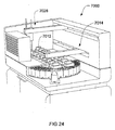
注入プローブは、例えば、Fluid Transfer Probe(FTP)ロボット7028(永久または一時的ピペット先端を用いて)または、図24に示したタイプのように、自動機器7000のBulk Fluid Robot(BFR)7014でもよい。一実施形態において、FTPまたはBFRは、カバー部材1000をスライド200の上に位置決めするために用いてもよく、両者間にチャンバ1300を形成する。図24において、複数のカバー部材が、機器7000内の個々のサンプル処理モジュール7012において示される。これらの各々が独立に制御可能であり、そのため、個々の処理モジュール7012についての機器スループットが、機器内の他のモジュールで実施される処理手順に要する培養時間によって制限されない。
The infusion probe may be, for example, a Fluid Transfer Probe (FTP) robot 7028 (using a permanent or temporary pipette tip) or a Bulk Fluid Robot (BFR) 7014 of an
この配置において、機器は、低減した複雑性を有し、それは、カバー部材の配置のための専用ロボットが必要でないからである。カバー部材が、生体サンプルが戴置されたスライドと並置されると、それは、任意の適切な手段を用いて所定位置にクランプされ、処理手順の間は移動しない。図2において、矢印Cは、カバー部材に印加されるクランプ力の方向を示し、処理手順の間、その位置を維持する。 In this arrangement, the device has a reduced complexity because a dedicated robot for the arrangement of the cover member is not required. When the cover member is juxtaposed with the slide on which the biological sample is placed, it is clamped in place using any suitable means and does not move during the processing procedure. In FIG. 2, arrow C indicates the direction of the clamping force applied to the cover member and maintains its position during the processing procedure.
好都合には、カバー部材1000が位置決めされ、所定位置にクランプされると、カバー部材は、処理手順の間、スライド200に対して移動する必要がない。試薬をチャンバ内へ送り込むための正圧、及び/又は、チャンバを介して試薬を引き出すための真空の使用が、最も多くの処理手順を完了させるのに充分である。処理手順は、カバー部材1000およびスライド200の相対位置を移動させることなく完了できるため、大気へのサンプルの最小露出になる。従って、サンプルの脱水のリスクは低く、所定の処理手順の終わりに、サンプルは、搬送及び/又は追加処理のために、カバースリップで覆ってもよい。
Conveniently, once the
出口1022から引き出される前に、試薬が培養期間中にチャンバ内に残留してもよい。培養の際、サンプル(および試薬)の温度は、例えば、処理モジュールと関連した熱交換器を加熱または冷却することによって変更してもよい。典型的には、熱交換器は、加熱/冷却パッド5300(図6a〜図6c)の形態で設けられる。理想的には、熱交換器は、サンプル(およびチャンバ内の試薬)の温度を20〜95℃の範囲内で変化させる能力を有する。しかし、ある処理手順では、より高い温度(例えば、120℃まで)が必要になることもある。幾つかの試薬が、加熱工程の際、気泡形成をもたらすことがある。典型的には、気泡は、大気に通気した場合、入口ポート1012及び/又は出口ポート1022に向かって移動する。温度変化のレートは、例えば、迅速な遷移が必要であるPCRにおいて、処理手順の有効性にとって重要であろう。理想的には、熱交換器は、これらの変化に順応し、1つ以上の実施形態では、冷却する能力を有する。本発明の種々の態様において、熱交換器は、スライドの下方に位置決めされた加熱/冷却パッドとして図示される。しかしながら、熱交換器は、種々の実施形態において、カバー部材と結合または一体化してもよいことは理解すべきである。例えば、カバー部材は、高い熱質量を持つ金属ブロックを備えてもよく、サンプルを温めたり、能動的に冷却できる(例えば、冷凍によって)。代替として、加熱手段は、ヒーターパッド、RF、マイクロ波、及び/又は、対流手段を含んでもよく。冷却手段は、低温化(chilling)手段、フィン、及び/又はペルチェ効果クーラーを含んでもよい。更なる実施形態において、カバー部材は加熱及び/又は冷却してもよく、基板支持部が、組合せで加熱及び/又は冷却する。
Reagents may remain in the chamber during the culture period before being withdrawn from
典型的には、高価値試薬が、正圧ポンプ、例えば、シリンジポンプを用いて、「コンタクトモード」(即ち、プローブ先端が入口と嵌め合いコンタクトしている)で入口に送り込まれる。好ましくは、シリンジポンプの動作が、自動機器7000に関連したコントローラ7060の制御下にある。こうしてプローブ先端410が、首部1014内に嵌め合い状態で受け入れられると、シリンジポンプは作動して、アリコートの試薬をチャンバ内に送給する。この手法では、正圧を用いて試薬をチャンバ内に能動的に変位させることは、必要な試薬量、そして試薬がチャンバに入ってスライド上のサンプルを覆う時間を最小化する。
Typically, high value reagents are pumped into the inlet in “contact mode” (ie, the probe tip is mating and in contact with the inlet) using a positive pressure pump, eg, a syringe pump. Preferably, the operation of the syringe pump is under the control of a
チャンバ1300への試薬の強制送給の際、出口1022が大気圧に通気される。強制送給のレートを制御することは、スライド上で移動する際に、流体フロントについての制御を提供し、これによりチャンバ内での気泡形成のリスクを最小化する。幾つかの処理手順では、試薬は、特に粘性があることがあり、チャンバ内でスライド表面を横断する試薬の伝搬が、出口1022における真空の印加によって支援してもよい。必要な培養期間の後、試薬は、出口における真空の印加によって、あるいは、追加の試薬の注入で洗い流すことによって、チャンバから排出してもよい。矢印F(図2)が、チャンバ内に注入される試薬の流れ方向を示す。チャンバを横断して必要な圧力勾配を提供するために、弁(不図示)を設けてもよく、出口を大気または負圧供給源と切換え可能に接続するように動作可能である。
When the reagent is forcibly supplied to the
典型的な処理手順が、バルク流体試薬をチャンバ内に注入し、サンプルを洗浄または処理することを含む。洗浄工程の際、入口1012を洗い流して、例えば、コンタクトモードでの高価値(high value)試薬の強制送給の際に入口壁に付着した残留高価値試薬を除去することが望ましい。従って、バルク流体試薬を入口1012に注入するプローブが、案内手段/首部1014と嵌め合いコンタクトする必要はない。処理手順の種々の工程において、特定の試薬を「非コンタクトモード」で注入することが望ましく、その結果、嵌め合い表面は洗い流される。
A typical processing procedure involves injecting bulk fluid reagents into the chamber and washing or processing the sample. During the cleaning process, it is desirable to flush the
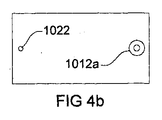
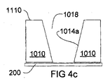
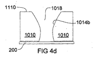
図4a〜図4eは、カバー部材1000について種々の入口形状の例を示す。図4a、図4c、図4dは、入口1012を通る端面図を表す。図4bは、図4aのカバー部材の平面図を表し、図4eは、図4bと図4cのカバー部材の平面図を表す。図4bと図4eに示すように、出口1022は、カバー部材の上部を出てもよく(即ち、第1表面を通る)、あるいは、図1〜図3のように、カバー部材の第2表面を通って出てもよく、あるいは、例えば、カバー部材の前方表面または後方表面を通って出てもよい。
FIGS. 4 a-4 e show examples of various inlet shapes for the
図4aは、図1〜図3のカバー部材の入口形状の変形例を示す。案内手段1014は、より多量の試薬を収容するように延びており、これにより貯留部1018を形成する。同様な貯留部1018が、図4cと図4dの入口形状に示される。貯留部1018は、1アリコートより多い試薬を保管するのに充分な体積を有する。貯留部1018を入口1012に設置する利点が、チャンバ1300に入る前に、複数の試薬の混合が可能になることである。他の利点が、試薬の幾つかの注入を保管することは、自動機器で用いられる注入ロボットに対する負荷を低減できることであり、これにより処理手順での工程間の大気時間を削減できる。さらに、図4cと図4dにおいて、より大きな楕円状の開口は、試薬注入ノズルを位置決めするために、自動機器ロボットによって実行される運動の複雑さを低減する。注入目標エリアがより大きいためである。貯留部1018からチャンバへの時期尚早の流体放出を緩和するため、カバー部材とともに使用される処理モジュールが、カバー部材を傾斜させて、出口を上昇させるように構成してもよく、これによりチャンバ内への試薬の放出を防止する。
FIG. 4a shows a modification of the inlet shape of the cover member of FIGS. The guiding means 1014 extends so as to accommodate a larger amount of reagent, thereby forming a
図3は、図1と図2のカバー部材の第2表面(下面)の概略図である。図3は、曲線輪郭境界壁1126を示す。第1端部に向いた曲線輪郭境界1126は、チャンバ1300内の流体の流動を支援する。第2端部1020に向いた曲線輪郭境界1126’は、洗浄または排出の後、チャンバ内部に残留する試薬及び/又は試薬残骸に対して不利に作用する。排出が、例えば、出口1022と結合した負圧供給源(即ち、真空)の作動によって達成でき、試薬をチャンバから引き出したり除去する。幾つかの実施形態において、曲線輪郭境界は、同じ幾何形状を有してもよいが、ここではその場合である必要がないことに留意する。例えば、図3において、曲線輪郭境界1126は、曲線輪郭境界1126’より小さい半径を有する。他の実施形態において(不図示)、曲線輪郭境界は、合体して、凹部の一端(または両端)においてテーパーを形成してもよく、その結果、凹部は、一端(または両端)において長円(obround)状または滑らかな矢印の形状を含む。しかしながら、こうしたテーパーの包含は、チャンバによって覆われるスライドのエリアを減少させることがあり、スライド染色の際、チャンバ内に注入される試薬の有効性を制限する。
FIG. 3 is a schematic view of the second surface (lower surface) of the cover member of FIGS. 1 and 2. FIG. 3 shows a curved
図3において、入口1012が出口1022と同様な直径を有する。しかし、ここではその場合である必要がない。図4bで判るように、凹部に入る入口開口の直径は、凹部を出る出口の直径より大きくてもよい。
In FIG. 3, the
図5a〜図7bは、2つの部品、即ち、カバー部材本体1100(図5a)およびカバー部材挿入部1200(図5b)で構成されたカバー部材1000の代替の実施形態を示す。図5cは、カバー部材本体およびカバー部材挿入部を一緒に示す。ここで、カバー部材本体1100は、カバー部材挿入部1200の対向する凸部(tongue)1250がスライド可能に受容される溝1150を有する。
Figures 5a-7b show an alternative embodiment of a
カバー部材本体1100での入口1012が、カバー部材挿入部での入口延長部1012’と結合するように配置される。同様に、図5bにおいて、カバー部材本体での出口1022が、出口延長部1022’と結合するように構成される。こうして入口/入口延長部および出口/出口延長部の結合が、凹部1124を有するカバー部材挿入部1200によって形成されるチャンバへの試薬の注入を容易にする。カバー部材挿入部1200は、スライド200と並置した場合(図6a〜図6c)、試薬チャンバを形成する。図5a〜図5cに示す配置は、カバー部材本体と、スライド係合を許容するカバー部材挿入部との間のカップリングを提供するが、他の配置、例えば、カバー部材を含む要素間の磁気カップリングおよび吸引カップリングも想定されることは理解すべきである。
An
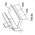
図6a〜図6cは、本発明の一実施形態に係る処理モジュール5000を示す。処理モジュール5000は、スライド200が支持される支持面5100を含む。必要に応じて、加熱/冷却パッド5300の形態(上述のように)での熱交換機が、支持面5100とスライド200との間に設けられ、処理手順の間、チャンバ内の試薬の温度を変更する。スライド200は、カバー部材/カバー部材挿入部の第2表面の下方に位置する。図6a〜図6cは、カバー部材1000をスライド200と並置するように位置決めするための駆動アーム5110を示す。クランプ部材3200が、処理手順の間、カバー部材1000およびスライド200を並置状態で保持するために設けられる。クランプ部材3200は、例えば、カバー部材1000に力を作用する捩りばねでもよい。
6a-6c show a
図示した実施形態は、カバー部材1000の長辺に位置決めされた駆動アーム5110を示しているが、駆動アームは、カバー部材1000の端部に設置してもよいことは理解すべきである。こうしてアーム5110は、カバー部材1000を長手方向に開閉するように動作可能でもよい。
Although the illustrated embodiment shows a
進歩した染色手順を実施することに追加して、除去可能/置換可能なカバー部材挿入部1200を組み込んだカバー部材1000が、ポリメラーゼ連鎖反応(PCR)手順を含む用途において有用であろう。これらの手順において、一方の手順から他方の手順への残骸の繰り越しが、検査サンプルの汚染および不良をもたらすことがある。従って、一方の検査から次の検査への繰り越しを完全に洗浄または排除することが必要である。こうして除去可能であって、理想的には使い捨て可能なカバー部材挿入部1200をカバー部材1000に組み込むことは、残骸の繰り越しまたはクロス汚染のリスクを排除または少なくとも低減でき、PCRなどの用途にとって望ましいであろう。
In addition to performing advanced staining procedures, a
図7aと図7bは、カバー部材の他の実施形態の概略図であり、駆動アーム5110を示している。カバー部材本体1100は、カバー部材挿入部1200とともに示される。図7aは、支持面5100の上にあるヒーターパッド5300の上に保持されたスライド200を伴う処理モジュール5000を示す。図7bにおいて、スライド200が除去されており、ヒーターパッド5300の表面5310および壁5320が洗浄ベイ(bay)5500を形成する。こうしてスライド200が処理手順の終わりに除去されると、カバー部材(またはカバー部材挿入部)の第2表面は、洗浄のために洗浄ベイ5500内に浸漬できる。洗浄試薬は、カバー部材挿入部1012/1012’を介して注入してもよく、出口1022/1022’を経由して引き出しもよい。代替として、洗浄試薬は、洗浄ベイ5500内に直接注入してもよく、機器搭載の廃棄物容器にまたは2次の入口ポートを介して配管された、洗浄ベイ内の廃棄口を通じて排出してもよい。こうした配置では、カバー部材挿入部は、半消耗品でもよく、例えば、5回、10回、15回、20回またはそれ以上の手順ごとに交換するように構成してもよい。
FIGS. 7 a and 7 b are schematic views of another embodiment of a cover member showing a
好ましい実施形態において、処理モジュール5000が、処理手順の終わりにカバー部材1000の除去の際、スライド200を支持面5100に保持するように構成された保持手段(例えば、図12を参照)をさらに含む。基板保持手段は、チャンバ内に残留する試薬に起因して、スライド表面とカバー部材/カバー部材挿入部との間で発生し得る接着摩擦力に打ち勝つために、特に重要であろう。
In a preferred embodiment, the
好都合には、図1〜図7のカバー部材は2つの運動だけを要し、一方、スライドは機器内にある。1つの運動は、カバー部材をスライドに印加するものであり、他方の運動は、カバー部材をスライドから除去して、処理したスライドが除去でき、及び/又は、新しいスライドが挿入できるようなアクセスを提供することである。自動機器内のロボットの必要な運動回数を最小化することは、特定サンプルの処理手順を完了するのに必要な所要(turnaround)時間を削減するとともに、機器の複雑さを低減する。さらに、試薬をチャンバ内に送り込むために正圧を利用する実施形態において、流体注入がより高速である。チャンバが毛細管現象で充填される待機時間を削減または排除できるためである。真空支援の充填が、サンプル処理のスループットを増加させる。 Conveniently, the cover member of FIGS. 1-7 requires only two movements, while the slide is in the instrument. One movement applies the cover member to the slide, and the other movement provides access such that the cover member can be removed from the slide so that the processed slide can be removed and / or a new slide can be inserted. Is to provide. Minimizing the required number of movements of the robot in an automated instrument reduces the turnaround time required to complete a particular sample processing procedure and reduces the complexity of the instrument. In addition, fluid injection is faster in embodiments that utilize positive pressure to deliver reagents into the chamber. This is because the waiting time for filling the chamber with capillary action can be reduced or eliminated. Vacuum assisted filling increases sample processing throughput.
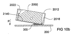
図8〜図15は、本発明の他の態様に係るカバー部材を示す。図8は、カバー部材2000を示し、カバー部材1000と同様に、第1端部2010と、第2端部2020と、第1表面2110と、第2表面2120とを有する。入口2012が第1端部に向けて設けられ、出口2022が第2端部に向けて設けられる。入口2012が貫通孔(不図示)の形態であり、入口2012もそうである。図9aと図9bは、カバー部材2000の断面図と側面図である。入口形状は、図4a〜図4eに示したように、複数の注入が井戸で受容できるように、変化してもよい。注入ノズルは、入口と接触する必要はない。
8 to 15 show a cover member according to another aspect of the present invention. FIG. 8 shows a
旋回軸2500が、カバー部材を通って、第1端部と第2端部との間に直交して延びる面に対して垂直に延びている。流体分散端部2128が設けられ、その周りにカバー部材が旋回する。図9cは、カバー部材2000の底面図を提供しており、分散端部2128が見えている。使用の際、カバー部材2000が開放状態にある場合、試薬が入口2012に注入され、分散端部2128およびスライド200によって形成される接合面(interface)に流れ出る。理想的には、カバー部材の第2表面2120およびスライド200は、試薬が入口に注入される場合、約10度の角度を形成する。しかし、他の角度の開口も想定される。表面張力が、いったん注入された流体の受動運動を安定化するともに、分散端部2128の周りのカバー部材2000の旋回運動が、分散端部2128から出口2022に向けて試薬の運動を促進する。スライド200とカバー部材2000との間の毛細管力が、スライドを横断して伝搬する際に、流体フロントを安定化し、気泡形成を低減する。
A
カバー部材1000と同様に、カバー部材2000は、凹部境界2122によって画定される凹部2124を提供し、これはカバー部材の第2端部に向かう曲線輪郭壁2126を有する。曲線輪郭壁2126は、チャンバの充填および排出の性能を改善する。図9cは、図9cは、凹部2124に開口した入口2012を示す。大きな開口は、流体の流れを阻止し、サンプル染色に悪影響を与える気泡の形成を回避するのに役立つ。凹部境界2122の周りの第2表面2120のエリアは、嵌め合い面を形成し、閉止状態で封止面2130を形成する。閉止状態において、カバー部材2000およびスライド200は、典型的には、培養期間は共にクランプされる。この状態では、試薬が、出口での真空の印加によって除去できる。
Similar to cover
先行技術のサンプル染色システムにおいて、よくある問題が、封止面に沿って形成されたチャンバ境界内での残骸および残留試薬の回収であった。本発明での曲線輪郭壁1126が試薬を出口に案内して、残骸回収を削減している。出口2022が凹部壁2122に接触して示されるが、こうした接触は不可欠ではないことと理解すべきである。むしろ凹部に開放した出口は、カバー部材のより内側に配置してもよく、凹部に入るその開口が凹部壁と整列していない。
In prior art sample staining systems, a common problem has been the collection of debris and residual reagents within the chamber boundary formed along the sealing surface. The
図8と図9a〜図9cにおけるカバー部材2000は、肩部2600を有し、カバー部材とともに使用できる処理モジュールの捩りばねと係合するための表面を提供する。捩りばねは、カバー部材の正しい傾斜角を確保する。これは、図13に関連してさらに説明している。
The
ここで、図10a〜図10dを参照して、カバー部材2000の簡略版を、スライド200に対して種々の配置状態で示している。図10aにおいて、スライド200およびカバー部材2000は、開放状態に位置決めされ、カバー部材2000は、スライド200と接触した分散端部2128で傾斜している。アリコートの試薬300が入口2012の中に注入され、カバー部材2000が方向Pに閉止位置に向かって徐々に旋回して、図10bに示すように、注入された試薬300がスライドを横断して伝搬するようにする。好ましくは、カバー部材2000を旋回させるレートは、試薬の流動特性に従って能動的に制御される。旋回レートを能動的に制御することは、スライド200とカバー部材2000との間の毛細管力を利用する。理想的には、カバー部材2000が閉止位置にある場合(図10c)、試薬は、スライド表面全体を横断して、または、少なくともサンプル表面全体を横断して注入される。毛細管現象を用いて試薬を能動的に変位させることは、チャンバ内の気泡形成のリスクを最小化する。
Here, with reference to FIGS. 10 a to 10 d, simplified versions of the
好ましい実施形態において、カバー部材の旋回運動は、自動サンプル処理機器のコントローラ7060によって制御される。典型的には、コントローラは、予めプログラムされた旋回運動のデータベース7126へのアクセスを有し、これは、複数の異なる試薬タイプ、及び/又は、種々の試薬タイプを採用する手順について、スライド200を横断する試薬の流れを増強または最適化する。こうした手順の幾つかでは、コントローラ7060は、カバー部材2000の僅かな動きによって試薬を撹拌するようにプログラムできる。代替/追加として、コントローラは、カバー部材の出口2020と連結した真空ポンプを動作させて真空を印加してもよく、これによりカバー部材は閉止状態のままで、チャンバを横断して試薬を引き出したり、または、チャンバから試薬を排出する。真空ポンプは、チャンバ内での流体撹拌を生じさせる方法で動作させてもよい。
In a preferred embodiment, the pivoting movement of the cover member is controlled by the automatic sample
図10dと図12は、取り外し状態にあるカバー部材を示し、カバー部材2000は、スライド200から分離している(即ち、切り離されている)。この状態で、機器のロボットアームが、スライド200を処理モジュール5000に投入または取り出したり、あるいは、カバー部材2000を洗浄、除去または置換できる。取り外し状態にあるカバー部材を洗浄することは、凹部の壁2122、天井および、スライドと接触するカバー部材封止面2130を含む、第2表面2120全体を洗浄することが可能になる。これは、カバー部材を、閉止状態で、例えば、洗い流しによって洗浄することを含む方法を改善する。他の試薬からの残骸が、スライド200とカバー部材2000との間の封止接合面を形成する「レール」に沿って残留するからである。好ましい実施形態において、取り外し状態にあるカバー部材の洗浄は、サンプル処理機器によって自動化され、機器に再投入する前での手動除去およびカバー部材の洗浄という時間を要する工程を排除する。洗浄試薬が、カバー部材から機器搭載の廃棄物容器の中に流出させることができ、有害である場合は処理され、幾つかの実施形態では再利用してもよい。
FIGS. 10d and 12 show the cover member in a removed state, with the
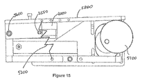
ここで、図11を参照して、カバー部材2000の概略図を示しており、入口2012および、チューブ2024が装着された出口2022を備え、好ましい実施形態では、チューブ2024は廃棄物容器に配管される。試薬は、典型的には、ロボットアーム、例えば、FTPまたはBFRによって入口に注入され、出口に向かって矢印Fの方向に進行する。第1表面2110に配置されたピン2550が、旋回アーム5200を用いてカバー部材2000と結合する(図13〜図15を参照)。
Referring now to FIG. 11, a schematic diagram of a
図12は、例えば、組織学的染色、PCRなど、生体サンプルの処理のための処理モジュール5000の要素の概略図である。カバー部材2000が、バーコードを付与した固有識別子領域210を有するスライド200の上に、閉止状態に設けられる。理想的には、処理モジュール5000は、固有識別子を読み取るための読取機7068を有し、スライド200によって運ばれるサンプル上で実施される処理手順と関連付ける自動サンプル処理機器7000の中に組み込まれる。典型的には、読取機7068は、例えば、手順における種々の工程で注入される試薬の量、スライドを横断して特定の試薬を引き出す毛細管現象を最大化するために、カバー部材が旋回するレート、試薬培養時間、必要に応じて、培養温度、撹拌条件などの手順情報を含むデータベース7126へのアクセスを有するコントローラ7060と通信する。
FIG. 12 is a schematic diagram of elements of a
好ましい実施形態において、機器コントローラ7060は、旋回アーム5200の動作を制御し、カバー部材2000を分散端部2128の周りに旋回させ、カバー部材を開放状態(図10a、図10b)と閉止状態(図10c、図12)の間で徐々に移動させる。理想的には、旋回運動は、分散端部からサンプルおよびスライドを横断する試薬の流れを最適化するレートである。スライド200と凹部の天井2140との間の毛細管を活用することは、この動きを増強する。理想的な旋回レートが、少なくとも部分的には、試薬の粘性によって決定される。しかし、それは、内面仕上げ、コーティング及び/又はチャンバの幾何形状によって影響を受けるであろう。
In a preferred embodiment, the
処理手順の終わりに、カバー部材2000は、スライドから分離され、スライドは、処理モジュールから除去される。分離は、カバー部材2000を開放状態に旋回することによって、及び/又は、カバー部材2000をスライド200から変位させることによって(逆も同様)、達成してもよく、これらは取り外し状態(図10d、図13)に分離される。いずれの場合も、チャンバ内に残留する試薬が、接着摩擦力を生じさせることがあり、これは、スライドおよびカバー部材2000を分離させるために打ち勝つ必要がある。こうして、好ましい実施形態において、処理モジュール5000は、カバー部材2000をスライドから分離する際、スライド200を支持面5100に保持するように構成されたスライド保持手段5400を設ける。図示した実施形態において、スライド保持手段5400は、支持面5100に向かってバイアスされた弾性部材であり、そのためカバー部材2000が閉止状態にある場合、カバー部材の下方から突出したスライド200の一部が、スライド保持手段5400と支持面5100との間に保持される。しかしながら、種々の代替的構成、例えば、突起(prong)またはレールと支持面との間にスライドを保持したり、磁気保持手段などが想定されることは理解すべきである。
At the end of the processing procedure, the
図13は、図12の処理モジュール5000の側面図である。カバー部材2000が、ピン2550によって旋回アーム5800と結合している。カバー部材2000が取り外し状態から開放状態へ移動する前に、カバー部材の肩部2600と係合した捩りばね5750が適切な傾斜配向を確保しており、試薬を受け入れる用意をする。カバー部材2000が閉止状態である場合、スライド保持手段5400がスライドと接触し、そして、スライド200を所定場所に保持して、処理手順の終わりにカバー部材およびスライドが分離される際に存在し得る接着摩擦力に打ち勝つ。
FIG. 13 is a side view of the
図14と図15は、本発明の一実施形態に係る処理モジュールの要素の概略図である。支持面5100上のスライド200が、カバー部材2000の下方に位置している。支持面5100は、基板を所定位置に案内し、及び/又は、異なる幅の基板を投入するための基準ポイントとして機能する位置決め部材、例えば、ピン5110,5112,5114などを組み込んでもよい。カバー部材2000が、ピン2550によって旋回アーム5800と結合している。遠位端では、旋回アーム5800が、開放カム5700と接触し、アームを第2軸5600の周りに旋回させ、カバー部材2000をスライド200に向けて又は遠ざかるように変位させ、そして、カバー部材を、取り外し状態、そしてカバー部材2000の分散端部2128がスライドと接触する開放状態に移動させるように動作可能である。理想的には、旋回アーム(または他の駆動機構)が移動する速度プロファイルは最適化され、その結果、スライド200およびカバー部材2000が切り離されたままの運動が、カバー部材の分散端部がスライドと接触しながら開放状態から閉止状態へ移動する際に行われる運動より速くなる。カバー部材2000が閉止状態に接近する場合、および開放時に接着摩擦力に打ち勝つ場合、速度が減少する。これらの運動の際、制御が最も重要であるためである。
14 and 15 are schematic diagrams of elements of a processing module according to an embodiment of the present invention. The
カバー部材を開放状態から閉止状態へ傾斜させるために、開放カム5700が、旋回アーム5800を下げて、「開放状態」ポイント(典型的には、カバー部材の第2表面とスライドとの間に約10度を形成する)を過ぎて、カバー部材を旋回軸2550の周りに回転させる。旋回軸の周りの旋回アームの同時回転が、カバー部材の旋回軸2550をスライドに向けてシフトさせ、その結果、カバー部材は、閉止状態に徐々に接近する。
In order to tilt the cover member from the open state to the closed state, an
好都合には、図14と図15に示す実施形態において、カバー部材を取り外し状態、開放状態および閉止状態の間で移動させるために、1つの運動軸だけが必要である。これは、任意のスライド厚さに適合できるという追加の利点を有する。しかしながら、旋回アームを使用して、カバー部材を閉止状態と開放状態の間で旋回させる他の配置も使用できることは理解すべきである。これは、例えば、旋回アームを上下させて、カバー部材を閉止状態と開放状態の間で移動させる直線ドライバとの組合せでもよい。いったん閉止すると、クランプ手段が、カバー部材およびスライドを閉止状態で一緒に保持するとともに、試薬を培養する。図示した実施形態において、クランプ手段は、ばね5200の形態であるが、旋回アームを駆動するために採用した駆動機構は、カバー部材およびスライドを閉止状態で能動的にクランプするためにも使用できる。
Conveniently, in the embodiment shown in FIGS. 14 and 15, only one axis of motion is required to move the cover member between the removed, open and closed states. This has the added advantage of being able to adapt to any slide thickness. However, it should be understood that other arrangements using the pivot arm to pivot the cover member between the closed and open states can be used. This may be, for example, a combination with a linear driver that moves the cover member up and down to move between the closed state and the open state. Once closed, the clamping means holds the cover member and the slide together in a closed state and cultivates the reagent. In the illustrated embodiment, the clamping means is in the form of a
一実施形態において、防湿バリアが設けられ(例えば、図22に示すバリア)、例えば、可撓性スカートまたは蒸気覆いが設けられ、基板上のサンプルを覆って、チャンバが開放した場合にサンプルの乾燥または脱水を緩和する。理想的には、サンプル/試薬が暖められた場合、チャンバを開放する前に、それは周囲温度まで冷却され、サンプル脱水のリスクをさらに最小化している。防湿バリアは、カバー部材2000の一部として、あるいは、処理モジュール5000の一部として設けてもよい、
In one embodiment, a moisture barrier is provided (eg, the barrier shown in FIG. 22), eg, a flexible skirt or vapor wrap is provided to cover the sample on the substrate and dry the sample when the chamber is open. Or relieve dehydration. Ideally, if the sample / reagent is warmed, it is cooled to ambient temperature before opening the chamber, further minimizing the risk of sample dehydration. The moisture barrier may be provided as a part of the
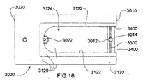
図16〜図22は、本発明のさらに他の態様に係るカバー部材の概略図である。カバー部材は、入口3012と、出口3022と、第1端部3010と、第2端部3020とを含む。凹部3124が、凹部壁3122によって境界設定され、カバー部材がスライド200と接触した場合、符号3130の第2表面の外側領域が封止面を形成する(図17〜図21)。入口の形状は、例えば、図4a〜図4eに示したように、変化してもよく、そのため、複数の注入が井戸で受容できる。注入ノズルは、入口と接触する必要はない。
16 to 22 are schematic views of a cover member according to still another aspect of the present invention. The cover member includes an
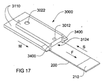
図17の等角図は、カバー部材3000の第1表面3110(即ち、上面)を示し、サンプルタイプまたは必要な手順、あるいは、サンプルについてのケースまたはバッチの同一性を指定する固有識別子を運ぶための識別子部分210を有するスライド200を伴う。図17に示すように、カバー部材3000をスライド200の上に戴置した場合、凹部3124が、入口3012に注入された試薬を受け入れるためのチャンバを形成する。図17において、カバー部材およびスライドは開放状態である。図18は、長手断面での同じ配置を示す。
The isometric view of FIG. 17 shows the first surface 3110 (ie, the top surface) of the
好ましくは、入口は、複数の試薬注入を受容するように構成され、図18に示すように貯留部3018を形成する。他の配置(不図示)では、複数の個々の試薬注入を保管可能な試薬注入バッファが、入口3012と気密に結合してもよい。注入バッファは、注入位置と保持位置との間で回転可能なバレル(barrel)を備えてもよい。注入位置に回転した場合、必要量の試薬が入口の中に放出され、分散チャネルの中に流入する。そこでは、流体メニスカスが、試薬をチャネル3300内のスペース3500に流入させる。こうした注入バッファの利用により、自動機器内のBFRまたはFTPロボットによって必要とされる個々の注入の回数を削減する。
Preferably, the inlet is configured to receive a plurality of reagent injections and forms a
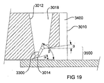
図19は、本発明の一実施形態に係る流体分散機構3300の詳細を示す拡大断面図である。カバー部材3000の使用の際、試薬が入口3012に注入され、貯留部3018内に保持される。貯留部3018での流体が、入口孔3014を通って流出し、流体の表面張力を利用して、図16に示すように、スライド200の幅を横断して延びる流体注入チャネル3300を充填する。図19に図示した実施形態において、チャネルは、カバー部材の第1端部に向かって高さが増加する滑らかな段差状の外形を有する。これにより、チャネル3300は、ある体積の試薬をスペース3500内に保持することが可能になり、開放状態から閉止状態への運動の際、スライド200を横断して徐々に伝搬しながら、流体フロントを供給する。
FIG. 19 is an enlarged cross-sectional view showing details of a
好ましい実施形態において、スペース3500は、約130μlのチャンバ体積で約2.5mmの高さを有する。段差状の外形は種々の角度をなし、αは約15度、βは約60度、θは約8度である。さらに、曲線輪郭凹部境界3126(図16)が、好ましくは、約9mmの半径を有する。出口3022が設けられ、約1.3mmの直径を有する、凹部に開放した出口が、チャンバから試薬の効率的な排出に適していることが判った。
In a preferred embodiment, the
スペース3500内に保持された、ある量の試薬が、分散チャネル3300およびスライド200の両方に接触する。チャネル3300の形状は、流体内の表面張力がチャネルからスライドへの漏出を防止するように、輪郭付与される。好ましい実施形態において、カバー部材3000には、流体分散機構の一部を形成する側壁3400が設けられる。側壁3400は、流体壁を形成するスペース3500の境界を完成する。
A quantity of reagent held in
チャンバの幅を横断するチャネルの配置は、スライド200およびカバー部材3000を、重なり係合にスライド移動させることによって、スライド200を横断する試薬の分散を促進する構造を提供する。一実施形態において、これは、カバー部材3000を静止保持しつつ、スライド200を方向Sに移動させることによって達成され、これによりチャネル3300およびスペース3500にある流体を、スライド表面に沿って方向Fに浸み出させる。代替として、スライド200を静止保持しつつ、カバー部材3000を方向Mに移動してもよい。これは、分散チャネル3300およびスペース3500内の流体をスライド表面に沿って方向Fに引き出すという効果がある。こうして一実施形態において、開放状態(図17、図18)から閉止状態(図20、図21)へのスライドおよびカバー部材3000の相対運動によって、試薬がスライド200の表面を横断するように分散する。この方法は、以下、「開放」注入と称する。
The arrangement of channels across the width of the chamber provides a structure that facilitates the distribution of reagents across the
好ましくは、閉止するレートは、試薬の流動特性に従って能動的に制御される。より高い粘性を有する試薬は、より低速な閉止速度を必要とし、その結果、閉止の際に発生する剪断力が、流体がスライド200を横断して引き出される際に、流体フロントを供給する流体壁をスペース3500内に保持する毛細管/表面張力に克服しなくなる。こうして試薬を注入することにより、チャンバ3124内での気泡形成のリスクを最小化している。
Preferably, the closing rate is actively controlled according to the flow characteristics of the reagent. Reagents with higher viscosities require a slower closing speed so that the shear force generated upon closing provides a fluid wall that provides the fluid front as the fluid is drawn across the
好ましい実施形態において、カバー部材3000及び/又はスライド200のスライド運動は、上述したタイプの自動サンプル処理機器7000のコントローラ7060によって制御される。典型的には、コントローラは、機器によって実施される処理手順で採用される種々の試薬に対応して、予めプログラムされたスライド特性のデータベース7126へのアクセスを有する。こうしてコントローラ7060は、スライド表面を横断する試薬の流れを最適化するアクチュエータの動作を制御するように構成される。こうしたコントローラの一例を図25に示す。幾つかの手順では、コントローラはまた、閉止状態のままで、カバー部材またはスライドの小さな動きを生じさせることによって試薬を撹拌するようにプログラムできる。
In a preferred embodiment, the sliding movement of the
コントローラ7060は、図25に概略的に示しており、プロセッサ7090を含み、これは、通信基盤7096を経由して、コンピュータプログラムコードを保存するための第1メモリ素子7092と、コンピュータプログラムコードを実行した場合、プロセッサ7090によって発生したデータを保存するための第2メモリ素子7094と通信する。ディスプレイ・インタフェース7098および対応するディスプレイ7100が、コントローラ7060とのユーザ相互作用を可能にする。
The
コントローラ7060はまた、モータ、ポンプ、スキャナ/読取機、熱交換器、および、装置7000の動作に必要な他のデバイス7114〜7124を制御するためのドライバモジュール7102〜7112を含む。染色手順(例えば、BFR 7014およびFTPロボット7028によってスライドへ注入される試薬の順序、および対応する培養時間)を含む処理手順が、通信基盤7096を経由してプロセッサ7090によってアクセス可能な手順データベース7126に保存され、これによりプロセッサ7090は、BFR 7014およびFTPロボット7028を動作させて、スライド処理ステーションにおいて必要なレートで試薬を基板に注入できる。
他の実施形態において、カバー部材3000およびスライド200が閉止状態のままで、流体が注入される。この方法は、以下、「閉止」注入と称しており、より水性の流体に適している。閉止注入は、流体の毛細管現象に依拠しており、スライドまたはカバー部材の運動によってもたらされる広がり運動ではなく、試薬はスライドの上に分散する。
In other embodiments, the fluid is injected while the
両方の開放および閉止の注入方法では、カバー部材3000およびスライド200によって形成されるチャンバは、大気へ通気することが必要である。図示した実施形態において、この通気は、チャンバから試薬を排出するために、弁またはソレノイド(不図示)を介して真空供給源と結合できる出口3022を介して提供される。しかしながら、カバー部材3000での出口3022を設ける必要がないことは理解すべきである。代わりに、閉止状態において、スライド200とカバー部材の第2端部3020との間に隙間を維持することが可能であり、チャンバは完全に閉止していない。こうして出口3022を省略して、代わりにスライドとカバー部材との間に隙間を設けて、チャンバが大気と直接に通気することにより、真空結合側の負担とともに、カバー部材の設計および製造を簡略化する。
In both open and closed injection methods, the chamber formed by the
サンプル処理手順の試薬注入工程が、第2試薬の注入に続いてもよい。これは、出口3022で真空と接続することによって、チャンバの排出を先行させてもよい。排出が、曲線輪郭凹部境界3126(図16)によって増強され、封止面3122の端部から試薬の排出を促進する。
The reagent injection step of the sample processing procedure may follow the injection of the second reagent. This may be preceded by evacuation of the chamber by connecting to a vacuum at the
好ましい実施形態において、いったん試薬がスライド200の上に注入され、カバー部材が開放状態に移動すると、サンプルから水分の蒸発を制御または制限するために、カバー部材3000には、防湿バリア3900が設けられる。物理的覆い(shroud)3900の形態での防湿バリアの一例を図22に示す。こうした覆いの設置により、いったんチャンバが開放されても、組織サンプルから散逸する水分の量を制限する。図22に示す実施形態において、防湿バリア3900は、スライドの長さ全体を覆うように構成される。しかしながら、これは必須ではない。スライド200の上を一部だけ延びた防湿バリアが、試薬用途間でサンプルの完全性を保存する程度に、及び/又は、追加の処理のためにカバースリップで覆って発送する前に、蒸発を制限するのに充分であってもよい。
In a preferred embodiment, the
防湿バリア3900は、スライド上のサンプルと干渉しないことが望ましい。従って、図22の防湿バリア3900は、天蓋上部を支持する壁部3910を有する相当に剛性のある天蓋(canopy)を備える。前方部3920が開放しても閉止してもよい。しかしながら、防湿バリア3900は、剛性または半剛性の構造である必要はないことと理解すべきである。むしろ、開放状態の場合、スライドの上に延びる可撓性のスカートまたはエプロンてせあってもよい。さらに、防湿バリアは、特定の実施形態において、カバー部材自体ではなく、カバー部材とともに使用される処理モジュールの一部を形成したり、またはこれに装着されてもよいことと理解すべきである。防湿バリアが可撓性である場合、サンプルを汚染したり破壊しないように、防湿バリアとスライド上のサンプルとの間に隙間を維持するように支持されることが望ましい。さらに他の実施形態において、防湿バリアは、ガスまたはエアロゾル化した水、または、いったんチャンバから出た後、サンプル内の水分を維持する他の適切な流体からなる蒸気バリアでもよい。
It is desirable that the
図23は、カバー部材3000を使用するのに適合した処理モジュール5000の一例を示しており、リニアアクチュエータ5900が、スライド200の上でカバー部材をスライド移動させ、開放状態から、入口3012に注入された試薬を、スライドによって運ばれるサンプルの上に分散させる閉止状態にする。
FIG. 23 shows an example of a
種々の態様において、本発明のカバー部材は、チャンバ内の流体の撹拌を可能にするように構成してもよい。撹拌が、チャンバ内の流体分子の運動を促進して、スライドの表面(処理すべきサンプルを支持する)と流体分子との間で有効な交換が存在することが望ましい。こうして流体の撹拌が、チャンバ内でより少ない試薬体積でより有効な処理を導くことができる。撹拌が、処理手順での特定工程について反応レートを増加させることができ、これにより工程間の所要時間を削減できる。さらに、チャンバ内の流体の撹拌が、チャンバ内で気泡を動き回すことによって、気泡の衝撃を低減でき、サンプルの各表面が、培養期間中に試薬流体に曝されることを確保できる。撹拌は、入口及び/又は出口ポートに印加された正圧及び/又は負圧、入口及び/又は出口ポートからの流体の導入及び/又は引き出し、または、入口及び/又は出口ポートを介して流体の流れを促進して、流体の撹拌を促進するのに充分な乱流を発生するような他の手段を含む、種々の手段を用いて達成できる。 In various aspects, the cover member of the present invention may be configured to allow agitation of fluid in the chamber. It is desirable that agitation promotes the movement of fluid molecules in the chamber so that there is an effective exchange between the surface of the slide (which supports the sample to be processed) and the fluid molecules. Thus, fluid agitation can lead to more effective processing with less reagent volume in the chamber. Agitation can increase the reaction rate for a particular step in the processing procedure, thereby reducing the time required between steps. In addition, agitation of the fluid in the chamber can reduce the impact of the bubbles by moving the bubbles around in the chamber, ensuring that each surface of the sample is exposed to the reagent fluid during the incubation period. Agitation may involve positive and / or negative pressure applied to the inlet and / or outlet port, introduction and / or withdrawal of fluid from the inlet and / or outlet port, or fluid flow through the inlet and / or outlet port. This can be accomplished using a variety of means, including other means to promote flow and generate sufficient turbulence to promote fluid agitation.
さらに、流体の撹拌は、気泡の存在に起因する染色アーチファクトを低減でき、チャンバ全体での内試薬の均一性を増強でき、「デッドゾーン」を最小化し、カバー部材の表面のその場(in situ)クリーニング及び/又は洗浄を容易にできる。チャンバ内の流体の運動が、チャンバ壁の曲線輪郭幾何形状によって増強される(例えば、図1を参照して説明したように)。輪郭輪郭は、流体の流れを増強するたに、カバー部材の入口端部に向けて設けてもよく、出口端部に向けて設けた場合は、チャンバからの改善した流体排出を提供でき、その結果、最小の残骸が残留する。 In addition, fluid agitation can reduce staining artifacts due to the presence of air bubbles, enhance internal reagent uniformity throughout the chamber, minimize "dead zones" and in situ on the surface of the cover member. ) Easy cleaning and / or cleaning. The motion of the fluid in the chamber is enhanced by the curved contour geometry of the chamber wall (eg, as described with reference to FIG. 1). The contour may be provided towards the inlet end of the cover member to enhance fluid flow, and if provided towards the outlet end, can provide improved fluid drainage from the chamber. As a result, the smallest debris remains.
代替/追加として、チャンバの一端または両端が、テーパーまたは湾曲した端部壁を形成する凹部壁によって定義してもよい。さらに、凹部の天井に、チャンバ内での試薬伝搬を増強する仕上げ(finish)を設けることが望ましい。仕上げは、凹部の天井を形成する第2表面において、例えば、波形加工(corrugation)、エッチング加工(etching)、ディンプル加工(dimpling)、矢印輪郭などのテキスチャ(texture)からなるものでもよい。凹部の天井を傾斜させたり、弓形加工したり、天井に波紋加工(ripple)を設けることにより、流体の流れを増強してもよい。代替/追加として、凹部の天井及び/又は壁は、コーティングまたは、流体の流れを増強する材料仕上げで処理してもよい。 As an alternative / addition, one or both ends of the chamber may be defined by a recessed wall forming a tapered or curved end wall. Furthermore, it is desirable to provide a finish on the ceiling of the recess to enhance reagent propagation within the chamber. Finishing may consist of texture such as corrugation, etching, dimpling, arrow contour, etc. on the second surface forming the ceiling of the recess. The fluid flow may be enhanced by inclining the ceiling of the recess, bowing, or providing a ripple on the ceiling. Alternatively / additionally, the ceiling and / or walls of the recess may be treated with a coating or material finish that enhances fluid flow.
本発明の種々の特徴が、機器7000によって採用される種類の処理手順の実施工程に必要な試薬量を最小化するカバー部材を生じさせる。理想的には、本発明の種々の態様が、120〜135μl程度の少ない体積を有し、カバー部材によって形成される効率的な反応チャンバを容易にする。しかし、30μl程度の少ない閉止体積も想定される。幾つかの反応において、例えば、最大で200μlの閉止体積を有するより大きな反応チャンバを提供することが必要であろう。
Various features of the present invention result in a cover member that minimizes the amount of reagent required to perform the type of procedure employed by
1つ以上の実施形態において、入口に注入される試薬のための液体レベル検知が望ましい。液体レベル検知は、プローブタッチ技術を用いて、及び/又は、注入プローブ先端での容量または圧力の変化を監視することによって行ってもよい。代替として、光学的液体レベル検知システムおよび超音波システムを採用してもよい。入口で、チャンバ内、及び/又は出口を通じて取られた試薬体積の測定が、自動機器7000に搭載されたコントローラ7060によって比較でき、実施した手順の回数に従って計算した注入量を照合する。この照合は、自動機器に搭載され保管された試薬の在庫管理のために使用できる。
In one or more embodiments, liquid level sensing for reagents injected into the inlet is desirable. Liquid level sensing may be performed using probe touch technology and / or by monitoring changes in volume or pressure at the injection probe tip. Alternatively, an optical liquid level sensing system and an ultrasound system may be employed. Reagent volume measurements taken at the inlet, in the chamber, and / or through the outlet can be compared by a
ここで説明した種々のカバー部材の実施形態は、1つの出口だけを示したが、複数の出口を設けてもよいことは理解すべきである。しかしながら、チャンバ内での流体の運動(撹拌を含む)を増強するため、及び/又は、試薬をチャンバから排出するために、真空が印加される場合、別個の真空供給源が出口の各々について必要になる。こうして本発明に係るカバー部材を設計する場合、当業者は、複雑さおよび価格を性能とバランスさせることになる。1つ以上の出口の各々が真空供給源と結合してもよいが、強制圧力注入(図1〜図3)および毛細管注入を利用する実施形態は、チャンバを大気と通気させることが必要になる。従って、出口は、真空供給源および大気との通気と交換可能に結合してもよい。 While the various cover member embodiments described herein show only one outlet, it should be understood that multiple outlets may be provided. However, a separate vacuum source is required for each of the outlets when a vacuum is applied to enhance fluid movement (including agitation) within the chamber and / or to expel reagents from the chamber. become. Thus, when designing a cover member according to the present invention, those skilled in the art will balance complexity and price with performance. Although each of the one or more outlets may be coupled with a vacuum source, embodiments utilizing forced pressure injection (FIGS. 1-3) and capillary injection require the chamber to be vented to the atmosphere. . Thus, the outlet may be interchangeably coupled to a vacuum source and air vent.
チャンバの充填中での真空の使用が、チャンバ内で形成される気泡の可能性を低減できる。さらに、流体をチャンバから排出するための真空の使用が、試薬注入間でチャンバ内に残留する残骸の可能性を削減する。試薬をチャンバから排出するための真空の使用の他の利点が、より少ない試薬が使用できることである。第2の試薬の付与前にチャンバから排出することは、混合のリスクを最小化するためである。 The use of a vacuum during chamber filling can reduce the possibility of bubbles forming in the chamber. Further, the use of a vacuum to drain fluid from the chamber reduces the possibility of debris remaining in the chamber between reagent injections. Another advantage of using a vacuum to expel reagent from the chamber is that less reagent can be used. Evacuating the chamber before application of the second reagent is to minimize the risk of mixing.
理想的には、自動機器コントローラ7060が、1つ以上の真空供給源を制御するために使用される処理手順情報のデータベース7128にアクセスし、使用する試薬(例えば、粘性または水性)、及び/又は、サンプルタイプまたは断面厚さ(例えば、皮膚サンプルまたは細胞学サンプルは、1μm〜15μm、好ましくは3μm〜5μmの厚さの範囲になり得る)に応じて、正しい大きさおよび真空持続期間を適用する。
Ideally, the
図示した実施形態において、入口の開口は、カバー部材の第1(上部)表面に設けているが、入口は、カバー部材本体に任意の配向で形成してもよく、そして任意の表面でカバー部材を出てもよいことに留意する。さらに、1つの入口を持つ各実施形態を図示したが、複数の入口の設置も想定されることに留意する。同様に、上述のように、複数の出口が想定される。図示した実施形態は、カバー部材を第1(上部)表面および正面で出ている出口を示しているが(図1)、これらの出口は、任意の表面でカバー部材を出てもよいことは理解すべきである。出口の開口の場所は、出口を真空供給源と接続するカップリング及び/又は導管の場所、及び/又は、出口が真空供給源と結合するため、及び/又は、大気に通気するための弁またはソレノイドの場所に影響されることがある。さらに、必須ではないが、カバー部材内部で出口を凹部境界に接触させることは、チャンバからの試薬の排出を改善できる。 In the illustrated embodiment, the inlet opening is provided in the first (upper) surface of the cover member, but the inlet may be formed in the cover member body in any orientation, and the cover member on any surface. Note that you may leave. Furthermore, although each embodiment with one inlet is illustrated, it should be noted that installation of multiple inlets is also envisioned. Similarly, multiple outlets are envisioned as described above. Although the illustrated embodiment shows outlets exiting the cover member on the first (top) surface and front (FIG. 1), these outlets may exit the cover member on any surface. Should be understood. The location of the outlet opening can be the location of a coupling and / or conduit connecting the outlet with a vacuum source and / or a valve or for the outlet to couple with the vacuum source and / or to vent the atmosphere May be affected by solenoid location. Further, although not required, contacting the outlet with the recess boundary within the cover member can improve reagent drainage from the chamber.
本明細書を通じて、説明した実施形態は、ほぼ水平配向に維持されるスライドを参照して説明している。しかしながら、水平配向は必ずしも要求されず、支持面はスライドを傾斜面に支持してもよいことは理解すべきである。さらに、本発明は、カバー部材の第1端部から第2端部に向けて長手方向の流体伝搬の意味で説明している。しかしながら、カバー部材は、より幅広の流体フロントを採用したスライドを横断する横方向の流体の流れについて構成してもよく、本構成では気泡形成のリスクが高くなるかもしれないことは理解すべきである。本発明の実施形態に係るスライド処理は、水平配向での処理に限定する必要がないことも留意すべきである。 Throughout this specification, the described embodiments are described with reference to a slide that is maintained in a substantially horizontal orientation. However, it should be understood that a horizontal orientation is not necessarily required and that the support surface may support the slide on an inclined surface. Furthermore, the present invention is described in the meaning of fluid propagation in the longitudinal direction from the first end to the second end of the cover member. However, it should be understood that the cover member may be configured for lateral fluid flow across a slide that employs a wider fluid front, and this configuration may increase the risk of bubble formation. is there. It should also be noted that the slide processing according to embodiments of the present invention need not be limited to processing in a horizontal orientation.
好ましくは、本発明のカバー部材を自動サンプル処理機器で使用した場合、処理される各スライドが、サンプルタイプおよびサンプルに対して実施される手順の1つ以上を識別する固有の識別子、例えば、バーコードまたはRFIDタグなどを含む。その情報は、機器内の読取装置によって検出され、必要な処理手順に従って、機器内のBFRロボットおよびFTPロボットの注入運動をスケジュール決定するために使用される。 Preferably, when the cover member of the present invention is used in an automated sample processing instrument, each processed slide has a unique identifier that identifies one or more of the procedures performed on the sample type and sample, eg, a bar Includes code or RFID tags. That information is detected by a reader in the instrument and used to schedule the injection movement of the BFR and FTP robots in the instrument according to the required processing procedure.
用語「備える、含む」を本明細書(請求項を含む)で用いた場合、これらは、記載した特徴、整数、ステップまたは構成要素の存在を特定するものとして解釈すべきであるが、1つ以上の特徴、整数、ステップもしくは構成要素、またはこれらのグループの存在を除外していない。 Where the term “comprising” is used in this specification (including the claims), it should be construed as specifying the presence of the described feature, integer, step or component, but one The presence of the above features, integers, steps or components, or groups thereof is not excluded.
本発明の範囲から逸脱することなく、添付した請求項で定義されたものとして、前述した部品に対して種々の変更、追加及び/又は変化が可能であることは理解すべきである。 It should be understood that various changes, additions and / or changes can be made to the above-described parts as defined in the appended claims without departing from the scope of the invention.
Claims (119)
a)第1および第2対向端部と、
b)第1および第2対向表面と、
c)第2表面に存在し、基板と並置した場合にチャンバを形成する凹部と、
d)第1端部に向かって、凹部と流体連通した流体入口と、を備え、
凹部は、チャンバ内での流体移動を増強するための1つ以上の曲線輪郭領域を有する凹部壁によって境界が定められる、カバー部材。 A cover member for a substrate that supports a biological sample,
a) first and second opposing ends;
b) first and second opposing surfaces;
c) a recess which is present on the second surface and forms a chamber when juxtaposed with the substrate;
d) towards the first end, comprising a fluid inlet in fluid communication with the recess,
A cover member, wherein the recess is bounded by a recess wall having one or more curvilinear contour regions to enhance fluid movement within the chamber.
カバー部材挿入部は、基板とともにチャンバを形成するように構成される、請求項1〜13のいずれかに記載のカバー部材。 The cover member is formed of at least two parts including a cover member main body and a cover member insertion portion,
The cover member according to claim 1, wherein the cover member insertion portion is configured to form a chamber together with the substrate.
使用の際、カバー部材は、分散端部の周りに旋回するように構成され、
前記旋回運動は、分散端部から出口に向かって、入口での流体の移動を生じさせる、請求項1〜22のいずれかに記載のカバー部材。 A distributed end in fluid communication with the inlet;
In use, the cover member is configured to pivot about the dispersion end,
The cover member according to any one of claims 1 to 22, wherein the swirling motion causes movement of fluid at the inlet from the dispersion end toward the outlet.
前記分散機構は、毛細管現象を利用して、分散機構から基板表面に沿って流体を引き出す、請求項25記載のカバー部材。 The fluid distribution mechanism is configured to distribute the fluid in a closed state where the cover member overlaps at least a portion of the sample on the substrate;
26. The cover member according to claim 25, wherein the dispersion mechanism draws fluid along the substrate surface from the dispersion mechanism by using a capillary phenomenon.
a.請求項1〜33のいずれかに記載のカバー部材と、
b.生体サンプルを戴置した基板のための支持面と、
c.培養期間中、基板と並置した状態でカバー部材を取り外し可能に保持するように動作可能なクランプ手段と、を備える処理モジュール。 A processing module for a biological sample,
a. The cover member according to any one of claims 1 to 33,
b. A support surface for the substrate on which the biological sample is placed;
c. And a clamping means operable to detachably hold the cover member in a state of being juxtaposed with the substrate during the culture period.
旋回手段は、カバー部材を、開放状態に、そして、カバー部材および基板が並置してチャンバを形成する閉止状態に旋回させるように動作可能である、請求項34〜45のいずれかに記載の処理モジュール。 Swirling means configured to swivel the cover member around the dispersion end on the cover member to move fluid at the inlet from the dispersion end toward the outlet;
46. A process according to any of claims 34 to 45, wherein the pivoting means is operable to pivot the cover member into an open state and into a closed state in which the cover member and the substrate are juxtaposed to form a chamber. module.
カバー部材の第1端部の分散端部が基板と接触しており、第2表面が基板に対して1〜20度の角度で配置される、請求項46記載の処理モジュール。 The pivot means includes a pivot arm operable to position the cover member in an open state;
The processing module according to claim 46, wherein the dispersion end of the first end of the cover member is in contact with the substrate, and the second surface is disposed at an angle of 1 to 20 degrees with respect to the substrate.
a.第1および第2対向端部と、
b.第1および第2対向表面と、
c.第2表面に存在し、基板と並置した場合にチャンバを形成する凹部と、
d.第1端部に向かって、凹部と流体連通した流体入口と、
e.第2端部に向かって、凹部と流体連通した流体出口と、
f.入口において、流体を入口に方向付けるように構成された案内手段と、を備えるカバー部材。 A cover member for a substrate that supports a biological sample,
a. First and second opposing ends;
b. First and second opposing surfaces;
c. A recess that is present on the second surface and forms a chamber when juxtaposed with the substrate;
d. Toward the first end, a fluid inlet in fluid communication with the recess;
e. Towards the second end, a fluid outlet in fluid communication with the recess;
f. And a guide member configured to direct fluid at the inlet to the inlet.
a.サンプルを基板上に用意するステップと、
b.基板およびカバー部材を位置決めして、チャンバを形成するステップと、
c.注入プローブ先端を、流体入口との嵌め合いコンタクト状態に位置決めするステップと、
d.第1試薬が基板上のサンプルを実質的に覆うのに充分な力を用いて、第1体積の第1試薬を入口に送り込むステップと、を含む方法。 A method for culturing a biological sample with one or more reagents using the cover member according to any one of claims 58 to 62, comprising:
a. Preparing a sample on a substrate;
b. Positioning the substrate and cover member to form a chamber;
c. Positioning the infusion probe tip in mating contact with the fluid inlet;
d. Feeding the first volume of the first reagent to the inlet using a force sufficient to substantially cover the sample on the substrate.
正圧ポンプは、下記を含むグループから選択される、請求項63記載の方法。
a.シリンジポンプ
b.歯車ポンプ The first reagent is fed into the inlet by a positive pressure pump connected to the tip of the injection probe,
64. The method of claim 63, wherein the positive pressure pump is selected from the group comprising:
a. Syringe pump b. Gear pump
a.サンプルを基板上に用意するステップと、
b.基板およびカバー部材を位置決めして、チャンバを形成するステップと、
c.注入プローブ先端を位置決めして、試薬を流体入口に注入するステップと、
d.少なくとも第2体積の第2試薬を入口に注入するステップと、含む方法。 A method for culturing a biological sample with one or more reagents using the cover member according to any one of claims 58 to 62, comprising:
a. Preparing a sample on a substrate;
b. Positioning the substrate and cover member to form a chamber;
c. Positioning the injection probe tip and injecting a reagent into the fluid inlet;
d. Injecting at least a second volume of a second reagent into the inlet.
a.第1および第2対向端部と、
b.第1および第2対向表面と、
c.第2表面に存在し、基板と並置した場合にチャンバを形成する凹部と、
d.第1端部に向かって、凹部と流体連通した流体入口と、
e.第2端部に向かって、凹部と流体連通した流体出口と、
f.入口と流体連通している分散端部と、を備え、
カバー部材は、分散端部の周りに旋回するように構成され、使用の際、前記旋回運動は、入口において、分散端部から出口に向かう流体の移動を生じさせる、カバー部材。 A cover member for a substrate that supports a biological sample,
a. First and second opposing ends;
b. First and second opposing surfaces;
c. A recess that is present on the second surface and forms a chamber when juxtaposed with the substrate;
d. Toward the first end, a fluid inlet in fluid communication with the recess;
e. Towards the second end, a fluid outlet in fluid communication with the recess;
f. A distributed end in fluid communication with the inlet;
The cover member is configured to swivel about the dispersion end, and in use, the swiveling motion causes fluid movement at the inlet toward the outlet from the dispersion end.
a.請求項70〜72のいずれかに記載のカバー部材と、
b.生体サンプルを戴置した基板のための支持面と、
c.カバー部材を分散端部の周りに旋回させ、流体を入口から基板に沿って、分散端部から出口に向けて移動させるように構成された旋回手段と、を備え、
旋回手段は、カバー部材を、開放状態および、カバー部材および基板が並置されてチャンバを形成する閉止状態に旋回させるように動作可能である、処理モジュール。 A processing module for a biological sample,
a. A cover member according to any one of claims 70 to 72;
b. A support surface for the substrate on which the biological sample is placed;
c. Swiveling means configured to swivel the cover member around the dispersion end and to move the fluid from the inlet along the substrate toward the outlet from the dispersion end;
The pivoting means is operable to pivot the cover member to an open state and a closed state in which the cover member and the substrate are juxtaposed to form a chamber.
負圧供給源の各々は、−2kPa〜−15kPaの制御された真空を発生するように動作可能である、請求項73〜85のいずれかに記載の処理モジュール。 A coupling operable to interchangeably connect one or more outlets of the cover member with one or more individual negative pressure sources;
86. A processing module according to any of claims 73 to 85, wherein each of the negative pressure sources is operable to generate a controlled vacuum of -2 kPa to -15 kPa.
a.サンプルを基板上に用意するステップと、
b.分散端部が基板と接触するようにカバー部材に角度がついた開放状態に、基板およびカバー部材を位置決めするステップと、
c.第1試薬を入口に注入するステップと、
d.カバー部材を閉止状態に向けて旋回させて、旋回運動により、注入された試薬が基板上のサンプルを実質的に覆うようにするステップと、を含む方法。 A method for culturing a biological sample with one or more reagents using the processing module of any of claims 73-87, comprising:
a. Preparing a sample on a substrate;
b. Positioning the substrate and cover member in an open state in which the cover member is angled so that the dispersion end contacts the substrate;
c. Injecting a first reagent into the inlet;
d. Pivoting the cover member toward the closed state so that the pivoted movement substantially covers the injected reagent over the sample on the substrate.
a.第1および第2対向端部と、
b.第1および第2対向表面と、
c.第2表面に存在し、基板とともにチャンバを形成する凹部と、
d.第1端部に向かって、凹部と流体連通した流体入口と、
e.流体を注入する流体分散機構と、を備え、
流体分散機構は、流体を、入口から基板の少なくとも幅に分散するように構成される、カバー部材。 A cover member for a substrate that supports a biological sample,
a. First and second opposing ends;
b. First and second opposing surfaces;
c. A recess present in the second surface and forming a chamber with the substrate;
d. Toward the first end, a fluid inlet in fluid communication with the recess;
e. A fluid dispersion mechanism for injecting fluid, and
The fluid distribution mechanism is a cover member configured to distribute fluid from the inlet to at least the width of the substrate.
前記分散は、毛細管現象を利用して、流体分散機構から基板表面に沿って流体を引き出す、請求項96記載のカバー部材。 The fluid distribution mechanism is configured to inject fluid in a closed state where the cover member overlaps at least a portion of the sample on the substrate;
99. The cover member according to claim 96, wherein the dispersion uses capillary action to draw fluid along a substrate surface from a fluid dispersion mechanism.
前記体積は、基板上に徐々に広がる流体フロントを供給する、請求項99または100記載のカバー部材。 The channel is configured to store a volume of fluid from the inlet,
101. The cover member of claim 99 or 100, wherein the volume provides a fluid front that gradually spreads over the substrate.
a.サンプルを基板上に用意するステップと、
b.基板およびカバー部材を、流体分散機構の領域において基板の少なくとも端部がカバー部材の第2表面と並置された状態に設定された開放構成に位置決めするステップと、
c.試薬を入口に注入し、毛細管現象を利用して、基板を横断するように試薬を引き出すステップと、を含む方法。 A method for culturing a biological sample with one or more reagents using the cover member according to any one of claims 96 to 105, comprising:
a. Preparing a sample on a substrate;
b. Positioning the substrate and the cover member in an open configuration in which at least an end of the substrate is juxtaposed with the second surface of the cover member in the region of the fluid distribution mechanism;
c. Injecting a reagent into the inlet and utilizing capillary action to withdraw the reagent across the substrate.
前記スライド運動は、試薬を分散機構から基板に沿って引き出すようにした、請求項106記載の方法。 Sliding one of the substrate and cover member relative to the other of the substrate and cover member from an open state where the sample is external to the chamber to a closed state where the cover member covers at least a portion of the sample in the chamber. ,
107. The method of claim 106, wherein the sliding movement causes the reagent to be withdrawn from the dispersion mechanism along the substrate.
カバー部材および基板が閉止状態のままで、試薬が分散される、請求項108記載の方法。 Sliding one of the substrate and cover member relative to the other of the substrate and cover member into a closed state where the cover member covers at least a portion of the sample in the chamber prior to injecting the reagent into the inlet;
109. The method of claim 108, wherein the reagent is dispersed while the cover member and the substrate remain closed.
a.請求項96〜105のいずれかに記載のカバー部材と、
b.生体サンプルを戴置した基板のための支持面と、
c.サンプルがカバー部材によって覆われていない開放状態と、サンプルの少なくとも一部が、カバー部材および基板によって形成されるチャンバ内で覆われる閉止状態との間で、カバー部材および基板をスライド移動させるための直線移動装置と、を備える処理モジュール。 A processing module for a biological sample,
a. A cover member according to any one of claims 96 to 105,
b. A support surface for the substrate on which the biological sample is placed;
c. For sliding the cover member and the substrate between an open state where the sample is not covered by the cover member and a closed state where at least a portion of the sample is covered in a chamber formed by the cover member and the substrate. A processing module comprising a linear movement device.
負圧供給源の各々は、−2kPa〜−15kPaの制御された真空を発生するように動作可能である、請求項113〜117のいずれかに記載の処理モジュール。 A coupling operable to exchangeably connect one or more outlets of the cover member with one or more individual negative pressure sources;
118. A processing module according to any of claims 113 to 117, wherein each of the negative pressure sources is operable to generate a controlled vacuum of -2 kPa to -15 kPa.
Applications Claiming Priority (3)
| Application Number | Priority Date | Filing Date | Title |
|---|---|---|---|
| US201161560543P | 2011-11-16 | 2011-11-16 | |
| US61/560,543 | 2011-11-16 | ||
| PCT/AU2012/001407 WO2013071352A1 (en) | 2011-11-16 | 2012-11-15 | Cover member, method and treatment module for treating a biological sample on a substrate |
Related Child Applications (1)
| Application Number | Title | Priority Date | Filing Date |
|---|---|---|---|
| JP2017194980A Division JP6633586B2 (en) | 2011-11-16 | 2017-10-05 | Cover member, method for processing biological sample on substrate, and processing module |
Publications (2)
| Publication Number | Publication Date |
|---|---|
| JP2014533823A true JP2014533823A (en) | 2014-12-15 |
| JP2014533823A5 JP2014533823A5 (en) | 2016-01-14 |
Family
ID=48428835
Family Applications (2)
| Application Number | Title | Priority Date | Filing Date |
|---|---|---|---|
| JP2014541480A Pending JP2014533823A (en) | 2011-11-16 | 2012-11-15 | Cover member, biological sample processing method on substrate, and processing module |
| JP2017194980A Active JP6633586B2 (en) | 2011-11-16 | 2017-10-05 | Cover member, method for processing biological sample on substrate, and processing module |
Family Applications After (1)
| Application Number | Title | Priority Date | Filing Date |
|---|---|---|---|
| JP2017194980A Active JP6633586B2 (en) | 2011-11-16 | 2017-10-05 | Cover member, method for processing biological sample on substrate, and processing module |
Country Status (9)
| Country | Link |
|---|---|
| US (3) | US10549271B2 (en) |
| EP (1) | EP2780721B1 (en) |
| JP (2) | JP2014533823A (en) |
| CN (1) | CN104094122B (en) |
| AU (1) | AU2012339616B2 (en) |
| BR (1) | BR112014011935B1 (en) |
| CA (1) | CA2855511C (en) |
| IN (1) | IN2014CN04294A (en) |
| WO (1) | WO2013071352A1 (en) |
Cited By (4)
| Publication number | Priority date | Publication date | Assignee | Title |
|---|---|---|---|---|
| JP2015537202A (en) * | 2012-11-01 | 2015-12-24 | ライカ・バイオシステムズ・メルボルン・プロプライエタリー・リミテッドLeica Biosystems Melbourne Pty Ltd | Slide dyeing assembly and lid member |
| WO2016190111A1 (en) * | 2015-05-26 | 2016-12-01 | オリンパス株式会社 | Sample staining device and sample staining method |
| WO2021215755A1 (en) * | 2020-04-24 | 2021-10-28 | (주)바이오니아 | Trackable precise-sample-injection device for multi-well plate |
| JP7466515B2 (en) | 2018-07-10 | 2024-04-12 | ナノサイトミクス,エルエルシー | AUTOMATED SAMPLE DEPOSITION AND STAINING SYSTEM AND ASSOCIATED METHODS - Patent application |
Families Citing this family (20)
| Publication number | Priority date | Publication date | Assignee | Title |
|---|---|---|---|---|
| US9075225B2 (en) | 2009-10-28 | 2015-07-07 | Alentic Microscience Inc. | Microscopy imaging |
| CN105974571B (en) | 2009-10-28 | 2019-05-28 | 阿兰蒂克微科学股份有限公司 | Micro-imaging |
| AU2013337608B2 (en) * | 2012-11-01 | 2017-07-20 | Leica Biosystems Melbourne Pty Ltd | A fluid transport system |
| US10502666B2 (en) | 2013-02-06 | 2019-12-10 | Alentic Microscience Inc. | Sample processing improvements for quantitative microscopy |
| CN110058005A (en) | 2013-06-26 | 2019-07-26 | 阿兰蒂克微科学股份有限公司 | It is improved for micro- sample treatment |
| WO2015051295A1 (en) | 2013-10-04 | 2015-04-09 | Biogenex Laboratories, Inc. | Assembly for forming microchamber for inverted substrate |
| US10137450B2 (en) * | 2014-07-18 | 2018-11-27 | Tecan Trading Ag | Microfluidics cartridge with pipetting guide |
| US9958362B1 (en) * | 2015-10-02 | 2018-05-01 | The Florida State University Research Foundation, Inc. | Microscope sample preparation device |
| WO2018022025A1 (en) * | 2016-07-26 | 2018-02-01 | Hewlett-Packard Development Company, L.P. | Microfluidic apparatuses |
| GB2562081B (en) | 2017-05-04 | 2020-07-15 | Imrali Ahmet | Slide cleaner |
| EP3441143B1 (en) * | 2017-08-08 | 2022-04-13 | Roche Diagnostics GmbH | Laboratory instrument base plate |
| CN108152109B (en) * | 2017-12-14 | 2021-02-09 | 深圳达盟生物科技有限公司 | Slide glass cover body and method for cleaning tissue section by using same |
| CN108387428A (en) * | 2018-02-26 | 2018-08-10 | 深圳安诺康生物医疗有限公司 | A kind of colouring method of pathological section |
| KR102246609B1 (en) * | 2018-08-01 | 2021-04-30 | 주식회사 미코바이오메드 | Device for amplifying nucleic acid comprisng a plurality of heating blocks |
| AU2019404614A1 (en) * | 2018-12-20 | 2021-04-15 | Leica Biosystems Melbourne Pty Ltd | Bulk fluid wash module |
| KR20210104648A (en) * | 2018-12-20 | 2021-08-25 | 라이카 바이오시스템즈 멜버른 피티와이 엘티디 | slide output module |
| CN109900542A (en) * | 2019-03-15 | 2019-06-18 | 深圳市金准生物医学工程有限公司 | The cavity device for the self-closed that test card incubates |
| CN115773920B (en) * | 2021-09-06 | 2024-04-19 | 南京泰立瑞信息科技有限公司 | Low-loss and automatic slice sample dyeing method and system |
| HUP2200032A1 (en) * | 2022-02-04 | 2023-08-28 | 3Dhistech Kft | Microscope slide cover device and incubation chamber containing such a microscope slide cover device |
| CN116814864B (en) * | 2023-08-30 | 2023-11-24 | 深圳赛陆医疗科技有限公司 | Chip transfer control method, device, equipment, system and medium in gene sequencing |
Citations (9)
| Publication number | Priority date | Publication date | Assignee | Title |
|---|---|---|---|---|
| JPH04507295A (en) * | 1989-08-23 | 1992-12-17 | ロイヤル・ポストグラデュエイト・メディカル・スクール | In situ hybridization device for cell specimens mounted on slides |
| US5346672A (en) * | 1989-11-17 | 1994-09-13 | Gene Tec Corporation | Devices for containing biological specimens for thermal processing |
| JPH11502926A (en) * | 1995-03-28 | 1999-03-09 | メディカル・リサーチ・カウンシル | Improvements in or related to sample processing |
| US6673620B1 (en) * | 1999-04-20 | 2004-01-06 | Cytologix Corporation | Fluid exchange in a chamber on a microscope slide |
| JP2005530208A (en) * | 2002-06-20 | 2005-10-06 | ビジョン・バイオシステムズ・リミテッド | Microscope slide cover with integrated container |
| JP2005530165A (en) * | 2002-06-20 | 2005-10-06 | ビジョン・バイオシステムズ・リミテッド | Biological reaction device with fluid discharge mechanism |
| JP2007078490A (en) * | 2005-09-13 | 2007-03-29 | Canon Inc | Biochemical reaction cassette improving liquid filling property |
| WO2011060387A1 (en) * | 2009-11-13 | 2011-05-19 | Ventana Medical Systems, Inc. | Thin film processing apparatuses for adjustable volume accommodation |
| WO2011069507A1 (en) * | 2009-12-09 | 2011-06-16 | Dako Denmark A/S | An apparatus and method for processing biological samples |
Family Cites Families (8)
| Publication number | Priority date | Publication date | Assignee | Title |
|---|---|---|---|---|
| US5188963A (en) | 1989-11-17 | 1993-02-23 | Gene Tec Corporation | Device for processing biological specimens for analysis of nucleic acids |
| US5364790A (en) * | 1993-02-16 | 1994-11-15 | The Perkin-Elmer Corporation | In situ PCR amplification system |
| AUPN357495A0 (en) * | 1995-06-15 | 1995-07-06 | Australian Biomedical Corporation Limited | Coverslip pick-up and laydown apparatus |
| US6474386B2 (en) * | 1999-08-25 | 2002-11-05 | Kabushiki Kaisha Tiyoda Seisakusho | Cover glass adhering device |
| JPWO2003055973A1 (en) * | 2001-12-26 | 2005-05-12 | オリンパス株式会社 | Reaction vessel and reaction vessel holding mechanism |
| DE10352716A1 (en) * | 2003-11-05 | 2005-06-16 | Einsle, Xaver | platform |
| US7934417B2 (en) * | 2004-02-20 | 2011-05-03 | Markus Hund | Scanning probe microscope |
| WO2011008415A2 (en) * | 2009-07-17 | 2011-01-20 | Ventana Medical Systems, Inc. | Cover tile for treating a substrate with a fluid |
-
2012
- 2012-11-15 JP JP2014541480A patent/JP2014533823A/en active Pending
- 2012-11-15 AU AU2012339616A patent/AU2012339616B2/en active Active
- 2012-11-15 CA CA2855511A patent/CA2855511C/en active Active
- 2012-11-15 IN IN4294CHN2014 patent/IN2014CN04294A/en unknown
- 2012-11-15 EP EP12849833.4A patent/EP2780721B1/en active Active
- 2012-11-15 US US14/357,888 patent/US10549271B2/en active Active
- 2012-11-15 BR BR112014011935-0A patent/BR112014011935B1/en not_active IP Right Cessation
- 2012-11-15 WO PCT/AU2012/001407 patent/WO2013071352A1/en active Application Filing
- 2012-11-15 CN CN201280067038.XA patent/CN104094122B/en active Active
-
2017
- 2017-10-05 JP JP2017194980A patent/JP6633586B2/en active Active
-
2020
- 2020-01-03 US US16/733,935 patent/US11420200B2/en active Active
-
2022
- 2022-07-20 US US17/869,645 patent/US20230077728A1/en active Pending
Patent Citations (9)
| Publication number | Priority date | Publication date | Assignee | Title |
|---|---|---|---|---|
| JPH04507295A (en) * | 1989-08-23 | 1992-12-17 | ロイヤル・ポストグラデュエイト・メディカル・スクール | In situ hybridization device for cell specimens mounted on slides |
| US5346672A (en) * | 1989-11-17 | 1994-09-13 | Gene Tec Corporation | Devices for containing biological specimens for thermal processing |
| JPH11502926A (en) * | 1995-03-28 | 1999-03-09 | メディカル・リサーチ・カウンシル | Improvements in or related to sample processing |
| US6673620B1 (en) * | 1999-04-20 | 2004-01-06 | Cytologix Corporation | Fluid exchange in a chamber on a microscope slide |
| JP2005530208A (en) * | 2002-06-20 | 2005-10-06 | ビジョン・バイオシステムズ・リミテッド | Microscope slide cover with integrated container |
| JP2005530165A (en) * | 2002-06-20 | 2005-10-06 | ビジョン・バイオシステムズ・リミテッド | Biological reaction device with fluid discharge mechanism |
| JP2007078490A (en) * | 2005-09-13 | 2007-03-29 | Canon Inc | Biochemical reaction cassette improving liquid filling property |
| WO2011060387A1 (en) * | 2009-11-13 | 2011-05-19 | Ventana Medical Systems, Inc. | Thin film processing apparatuses for adjustable volume accommodation |
| WO2011069507A1 (en) * | 2009-12-09 | 2011-06-16 | Dako Denmark A/S | An apparatus and method for processing biological samples |
Cited By (9)
| Publication number | Priority date | Publication date | Assignee | Title |
|---|---|---|---|---|
| JP2015537202A (en) * | 2012-11-01 | 2015-12-24 | ライカ・バイオシステムズ・メルボルン・プロプライエタリー・リミテッドLeica Biosystems Melbourne Pty Ltd | Slide dyeing assembly and lid member |
| US10145767B2 (en) | 2012-11-01 | 2018-12-04 | Leica Biosystems Melbourne Pty Ltd | Slide staining assembly and cover member |
| US10718695B2 (en) | 2012-11-01 | 2020-07-21 | Leica Biosystems Melbourne Pty Ltd | Slide staining assembly and cover member |
| US11635356B2 (en) | 2012-11-01 | 2023-04-25 | Leica Biosystems Melbourne Pty Ltd | Slide staining assembly and cover member |
| WO2016190111A1 (en) * | 2015-05-26 | 2016-12-01 | オリンパス株式会社 | Sample staining device and sample staining method |
| JPWO2016190111A1 (en) * | 2015-05-26 | 2018-03-15 | オリンパス株式会社 | Specimen staining apparatus and specimen staining method |
| US10712244B2 (en) | 2015-05-26 | 2020-07-14 | Olympus Corporation | Specimen staining apparatus and specimen staining method |
| JP7466515B2 (en) | 2018-07-10 | 2024-04-12 | ナノサイトミクス,エルエルシー | AUTOMATED SAMPLE DEPOSITION AND STAINING SYSTEM AND ASSOCIATED METHODS - Patent application |
| WO2021215755A1 (en) * | 2020-04-24 | 2021-10-28 | (주)바이오니아 | Trackable precise-sample-injection device for multi-well plate |
Also Published As
| Publication number | Publication date |
|---|---|
| JP2018021932A (en) | 2018-02-08 |
| BR112014011935B1 (en) | 2020-11-03 |
| US10549271B2 (en) | 2020-02-04 |
| EP2780721B1 (en) | 2017-08-16 |
| CN104094122A (en) | 2014-10-08 |
| US20140315256A1 (en) | 2014-10-23 |
| BR112014011935A2 (en) | 2017-05-30 |
| CN104094122B (en) | 2017-03-22 |
| US20200188904A1 (en) | 2020-06-18 |
| US11420200B2 (en) | 2022-08-23 |
| CA2855511C (en) | 2021-03-09 |
| AU2012339616B2 (en) | 2016-04-28 |
| JP6633586B2 (en) | 2020-01-22 |
| WO2013071352A1 (en) | 2013-05-23 |
| IN2014CN04294A (en) | 2015-09-04 |
| US20230077728A1 (en) | 2023-03-16 |
| EP2780721A1 (en) | 2014-09-24 |
| AU2012339616A1 (en) | 2014-06-12 |
| CA2855511A1 (en) | 2013-05-23 |
| EP2780721A4 (en) | 2015-07-01 |
Similar Documents
| Publication | Publication Date | Title |
|---|---|---|
| JP6633586B2 (en) | Cover member, method for processing biological sample on substrate, and processing module | |
| US10900982B2 (en) | Automated high volume slide processing system | |
| EP2510329B1 (en) | An apparatus and method for processing biological samples | |
| US9989448B2 (en) | Specimen processing systems and methods for holding slides | |
| US10684200B2 (en) | Automatic tissue staining device and automatic tissue staining method | |
| CN104870974A (en) | Specimen processing systems and methods for preparing reagents | |
| CN104903697A (en) | Automated specimen processing systems and methods of aligning and transporting specimen-bearing microscope slides | |
| CN104870973A (en) | Specimen processing systems and methods for holding slides | |
| CN104870975A (en) | Opposables and automated specimen processing systems with opposables | |
| US11274998B2 (en) | Specimen processing systems and methods for holding slides | |
| US20180313863A1 (en) | Opposables incorporating onboard reagents and automated specimen processing systems | |
| US20230213417A1 (en) | Apparatus and method for processing biological samples | |
| WO2023036224A1 (en) | Device for freezing preservation or unfreezing resuscitation of biological tissue |
Legal Events
| Date | Code | Title | Description |
|---|---|---|---|
| A521 | Request for written amendment filed |
Free format text: JAPANESE INTERMEDIATE CODE: A523 Effective date: 20151116 |
|
| A621 | Written request for application examination |
Free format text: JAPANESE INTERMEDIATE CODE: A621 Effective date: 20151116 |
|
| A977 | Report on retrieval |
Free format text: JAPANESE INTERMEDIATE CODE: A971007 Effective date: 20160826 |
|
| A131 | Notification of reasons for refusal |
Free format text: JAPANESE INTERMEDIATE CODE: A131 Effective date: 20161004 |
|
| A601 | Written request for extension of time |
Free format text: JAPANESE INTERMEDIATE CODE: A601 Effective date: 20161227 |
|
| A521 | Request for written amendment filed |
Free format text: JAPANESE INTERMEDIATE CODE: A523 Effective date: 20170404 |
|
| A02 | Decision of refusal |
Free format text: JAPANESE INTERMEDIATE CODE: A02 Effective date: 20170606 |