JP2014531018A - Current sensor and printed circuit board for the current sensor - Google Patents
Current sensor and printed circuit board for the current sensor Download PDFInfo
- Publication number
- JP2014531018A JP2014531018A JP2014528982A JP2014528982A JP2014531018A JP 2014531018 A JP2014531018 A JP 2014531018A JP 2014528982 A JP2014528982 A JP 2014528982A JP 2014528982 A JP2014528982 A JP 2014528982A JP 2014531018 A JP2014531018 A JP 2014531018A
- Authority
- JP
- Japan
- Prior art keywords
- printed circuit
- circuit board
- coils
- magnetic
- magnetic ring
- Prior art date
- Legal status (The legal status is an assumption and is not a legal conclusion. Google has not performed a legal analysis and makes no representation as to the accuracy of the status listed.)
- Pending
Links
Images


Classifications
-
- G—PHYSICS
- G01—MEASURING; TESTING
- G01R—MEASURING ELECTRIC VARIABLES; MEASURING MAGNETIC VARIABLES
- G01R33/00—Arrangements or instruments for measuring magnetic variables
- G01R33/0052—Manufacturing aspects; Manufacturing of single devices, i.e. of semiconductor magnetic sensor chips
-
- G—PHYSICS
- G01—MEASURING; TESTING
- G01R—MEASURING ELECTRIC VARIABLES; MEASURING MAGNETIC VARIABLES
- G01R19/00—Arrangements for measuring currents or voltages or for indicating presence or sign thereof
- G01R19/0092—Arrangements for measuring currents or voltages or for indicating presence or sign thereof measuring current only
-
- G—PHYSICS
- G01—MEASURING; TESTING
- G01R—MEASURING ELECTRIC VARIABLES; MEASURING MAGNETIC VARIABLES
- G01R15/00—Details of measuring arrangements of the types provided for in groups G01R17/00 - G01R29/00, G01R33/00 - G01R33/26 or G01R35/00
- G01R15/14—Adaptations providing voltage or current isolation, e.g. for high-voltage or high-current networks
- G01R15/18—Adaptations providing voltage or current isolation, e.g. for high-voltage or high-current networks using inductive devices, e.g. transformers
- G01R15/183—Adaptations providing voltage or current isolation, e.g. for high-voltage or high-current networks using inductive devices, e.g. transformers using transformers with a magnetic core
- G01R15/185—Adaptations providing voltage or current isolation, e.g. for high-voltage or high-current networks using inductive devices, e.g. transformers using transformers with a magnetic core with compensation or feedback windings or interacting coils, e.g. 0-flux sensors
-
- G—PHYSICS
- G01—MEASURING; TESTING
- G01R—MEASURING ELECTRIC VARIABLES; MEASURING MAGNETIC VARIABLES
- G01R33/00—Arrangements or instruments for measuring magnetic variables
-
- G—PHYSICS
- G01—MEASURING; TESTING
- G01R—MEASURING ELECTRIC VARIABLES; MEASURING MAGNETIC VARIABLES
- G01R33/00—Arrangements or instruments for measuring magnetic variables
- G01R33/02—Measuring direction or magnitude of magnetic fields or magnetic flux
- G01R33/04—Measuring direction or magnitude of magnetic fields or magnetic flux using the flux-gate principle
- G01R33/045—Measuring direction or magnitude of magnetic fields or magnetic flux using the flux-gate principle in single-, or multi-aperture elements
-
- G—PHYSICS
- G01—MEASURING; TESTING
- G01R—MEASURING ELECTRIC VARIABLES; MEASURING MAGNETIC VARIABLES
- G01R33/00—Arrangements or instruments for measuring magnetic variables
- G01R33/02—Measuring direction or magnitude of magnetic fields or magnetic flux
- G01R33/04—Measuring direction or magnitude of magnetic fields or magnetic flux using the flux-gate principle
- G01R33/05—Measuring direction or magnitude of magnetic fields or magnetic flux using the flux-gate principle in thin-film element
-
- H—ELECTRICITY
- H01—ELECTRIC ELEMENTS
- H01F—MAGNETS; INDUCTANCES; TRANSFORMERS; SELECTION OF MATERIALS FOR THEIR MAGNETIC PROPERTIES
- H01F38/00—Adaptations of transformers or inductances for specific applications or functions
- H01F38/20—Instruments transformers
- H01F38/22—Instruments transformers for single phase ac
- H01F38/28—Current transformers
- H01F38/30—Constructions
-
- H—ELECTRICITY
- H05—ELECTRIC TECHNIQUES NOT OTHERWISE PROVIDED FOR
- H05K—PRINTED CIRCUITS; CASINGS OR CONSTRUCTIONAL DETAILS OF ELECTRIC APPARATUS; MANUFACTURE OF ASSEMBLAGES OF ELECTRICAL COMPONENTS
- H05K1/00—Printed circuits
- H05K1/16—Printed circuits incorporating printed electric components, e.g. printed resistor, capacitor, inductor
- H05K1/165—Printed circuits incorporating printed electric components, e.g. printed resistor, capacitor, inductor incorporating printed inductors
-
- H—ELECTRICITY
- H01—ELECTRIC ELEMENTS
- H01F—MAGNETS; INDUCTANCES; TRANSFORMERS; SELECTION OF MATERIALS FOR THEIR MAGNETIC PROPERTIES
- H01F27/00—Details of transformers or inductances, in general
- H01F27/28—Coils; Windings; Conductive connections
- H01F27/2804—Printed windings
- H01F2027/2809—Printed windings on stacked layers
-
- H—ELECTRICITY
- H05—ELECTRIC TECHNIQUES NOT OTHERWISE PROVIDED FOR
- H05K—PRINTED CIRCUITS; CASINGS OR CONSTRUCTIONAL DETAILS OF ELECTRIC APPARATUS; MANUFACTURE OF ASSEMBLAGES OF ELECTRICAL COMPONENTS
- H05K1/00—Printed circuits
- H05K1/02—Details
- H05K1/0213—Electrical arrangements not otherwise provided for
- H05K1/0237—High frequency adaptations
- H05K1/0239—Signal transmission by AC coupling
-
- H—ELECTRICITY
- H05—ELECTRIC TECHNIQUES NOT OTHERWISE PROVIDED FOR
- H05K—PRINTED CIRCUITS; CASINGS OR CONSTRUCTIONAL DETAILS OF ELECTRIC APPARATUS; MANUFACTURE OF ASSEMBLAGES OF ELECTRICAL COMPONENTS
- H05K2201/00—Indexing scheme relating to printed circuits covered by H05K1/00
- H05K2201/08—Magnetic details
- H05K2201/083—Magnetic materials
- H05K2201/086—Magnetic materials for inductive purposes, e.g. printed inductor with ferrite core
-
- H—ELECTRICITY
- H05—ELECTRIC TECHNIQUES NOT OTHERWISE PROVIDED FOR
- H05K—PRINTED CIRCUITS; CASINGS OR CONSTRUCTIONAL DETAILS OF ELECTRIC APPARATUS; MANUFACTURE OF ASSEMBLAGES OF ELECTRICAL COMPONENTS
- H05K2201/00—Indexing scheme relating to printed circuits covered by H05K1/00
- H05K2201/09—Shape and layout
- H05K2201/09009—Substrate related
- H05K2201/09063—Holes or slots in insulating substrate not used for electrical connections
-
- H—ELECTRICITY
- H05—ELECTRIC TECHNIQUES NOT OTHERWISE PROVIDED FOR
- H05K—PRINTED CIRCUITS; CASINGS OR CONSTRUCTIONAL DETAILS OF ELECTRIC APPARATUS; MANUFACTURE OF ASSEMBLAGES OF ELECTRICAL COMPONENTS
- H05K2201/00—Indexing scheme relating to printed circuits covered by H05K1/00
- H05K2201/09—Shape and layout
- H05K2201/09209—Shape and layout details of conductors
- H05K2201/09218—Conductive traces
- H05K2201/09263—Meander
-
- H—ELECTRICITY
- H05—ELECTRIC TECHNIQUES NOT OTHERWISE PROVIDED FOR
- H05K—PRINTED CIRCUITS; CASINGS OR CONSTRUCTIONAL DETAILS OF ELECTRIC APPARATUS; MANUFACTURE OF ASSEMBLAGES OF ELECTRICAL COMPONENTS
- H05K2201/00—Indexing scheme relating to printed circuits covered by H05K1/00
- H05K2201/09—Shape and layout
- H05K2201/09209—Shape and layout details of conductors
- H05K2201/09654—Shape and layout details of conductors covering at least two types of conductors provided for in H05K2201/09218 - H05K2201/095
- H05K2201/09672—Superposed layout, i.e. in different planes
-
- H—ELECTRICITY
- H05—ELECTRIC TECHNIQUES NOT OTHERWISE PROVIDED FOR
- H05K—PRINTED CIRCUITS; CASINGS OR CONSTRUCTIONAL DETAILS OF ELECTRIC APPARATUS; MANUFACTURE OF ASSEMBLAGES OF ELECTRICAL COMPONENTS
- H05K2201/00—Indexing scheme relating to printed circuits covered by H05K1/00
- H05K2201/09—Shape and layout
- H05K2201/09209—Shape and layout details of conductors
- H05K2201/09654—Shape and layout details of conductors covering at least two types of conductors provided for in H05K2201/09218 - H05K2201/095
- H05K2201/097—Alternating conductors, e.g. alternating different shaped pads, twisted pairs; Alternating components
-
- H—ELECTRICITY
- H05—ELECTRIC TECHNIQUES NOT OTHERWISE PROVIDED FOR
- H05K—PRINTED CIRCUITS; CASINGS OR CONSTRUCTIONAL DETAILS OF ELECTRIC APPARATUS; MANUFACTURE OF ASSEMBLAGES OF ELECTRICAL COMPONENTS
- H05K2201/00—Indexing scheme relating to printed circuits covered by H05K1/00
- H05K2201/10—Details of components or other objects attached to or integrated in a printed circuit board
- H05K2201/10007—Types of components
- H05K2201/10151—Sensor
-
- H—ELECTRICITY
- H05—ELECTRIC TECHNIQUES NOT OTHERWISE PROVIDED FOR
- H05K—PRINTED CIRCUITS; CASINGS OR CONSTRUCTIONAL DETAILS OF ELECTRIC APPARATUS; MANUFACTURE OF ASSEMBLAGES OF ELECTRICAL COMPONENTS
- H05K3/00—Apparatus or processes for manufacturing printed circuits
- H05K3/46—Manufacturing multilayer circuits
Landscapes
- Physics & Mathematics (AREA)
- General Physics & Mathematics (AREA)
- Engineering & Computer Science (AREA)
- Condensed Matter Physics & Semiconductors (AREA)
- Power Engineering (AREA)
- Manufacturing & Machinery (AREA)
- Microelectronics & Electronic Packaging (AREA)
- Measuring Magnetic Variables (AREA)
- Measuring Instrument Details And Bridges, And Automatic Balancing Devices (AREA)
- Production Of Multi-Layered Print Wiring Board (AREA)
Abstract
【課題】 電流が流れる導線をプリント基板の導電トラックに接続する必要がない電流センサを提供する。【解決手段】 この電流センサにおけるプリント基板は、導線を受容するために、垂直軸に沿って、プリント基板を貫通している孔(5)と、この孔(5)を囲んでおり、かつ複数のメタライズ層の間に水平に延在している第1の磁性体リング(10)の形態を呈している磁心とを備えている。測定コイルおよび励磁コイルの機能を果たす1つ以上の第1のコイル(12、13)の各々の各ターンは、第1の磁性体リングの上方および下方に位置している各1つのメタライズ層に1つずつ形成されている2つの導電トラック(44、46)を主構成要素としており、これらの2つの導電トラック(44、46)は、電気絶縁層を貫通し、第1の磁性体リングの内側を通っている貫通電極(48)によって互いに電気的に接続されている。【選択図】図1PROBLEM TO BE SOLVED: To provide a current sensor which does not need to connect a conducting wire through which a current flows to a conductive track of a printed board. A printed circuit board in the current sensor includes a hole (5) passing through the printed circuit board along a vertical axis to receive a conductive wire, and surrounds the hole (5). And a magnetic core in the form of a first magnetic ring (10) extending horizontally between the metallized layers. Each turn of each of the one or more first coils (12, 13) serving as a measurement coil and an excitation coil is applied to each one metallization layer located above and below the first magnetic ring. Two conductive tracks (44, 46) formed one by one are the main constituent elements, and these two conductive tracks (44, 46) penetrate the electrical insulating layer and are formed on the first magnetic ring. They are electrically connected to each other by through electrodes (48) passing through the inside. [Selection] Figure 1
Description
本発明は、電流センサ、およびこの電流センサのためのプリント基板に関する。 The present invention relates to a current sensor and a printed circuit board for the current sensor.
頭字語PCB(プリント基板)としても知られているプリント基板は、1セットの電気部品の電気的接続を可能にする支持体である。このようなプリント基板は、一般に、積層プレートの形態を呈している。このプリント基板は、単層プリント基板である場合もあれば、多層プリント基板である場合もある。単層プリント基板は、各電気部品を相互に電気的に接続するための導電トラックがプリントされている、単一のメタライズ層のみしか備えていない。それに反して、多層プリント基板は、複数のメタライズ層、すなわち、少なくとも2層のメタライズ層、好ましくは4層または6層を超えるメタライズ層を備えている。以下の説明は、主として、このような多層プリント基板に関するものである。 A printed circuit board, also known as the acronym PCB (printed circuit board), is a support that allows electrical connection of a set of electrical components. Such a printed circuit board generally takes the form of a laminated plate. The printed circuit board may be a single-layer printed circuit board or a multilayer printed circuit board. A single-layer printed circuit board has only a single metallized layer on which conductive tracks for electrically connecting the electrical components to each other are printed. On the other hand, the multilayer printed circuit board includes a plurality of metallized layers, that is, at least two metallized layers, preferably four or more than six metallized layers. The following description mainly relates to such a multilayer printed circuit board.
各メタライズ層は、プリント基板を構成している積層プレートの層の1つであり、各メタライズ層には、各電気部品を相互に電気的に接続するための1つ以上の導電トラックが形成されている。各メタライズ層は平坦であり、積層プレートの表面と平行に延在している。一般に、メタライズ層は、導電材料(通常、銅などの金属)の一様な層の被着、およびこの一様な層の、その後の、導電トラックだけを残すようなエッチングによって得られる。 Each metallized layer is one of the layers of the laminated plate constituting the printed circuit board, and each metallized layer is formed with one or more conductive tracks for electrically connecting the electrical components to each other. ing. Each metallized layer is flat and extends parallel to the surface of the laminated plate. In general, the metallized layer is obtained by depositing a uniform layer of conductive material (usually a metal such as copper) and then etching this uniform layer, leaving only conductive tracks.
プリント基板の各メタライズ層は、電気絶縁材料から成る電気絶縁層によって、物理的に互いに分離されている。この電気絶縁材料は、高い絶縁耐力、すなわち,通常3MV/m以上、好ましくは10MV/m以上の絶縁耐力を有している。電気絶縁材料は、例えばエポキシ樹脂、および/またはガラス繊維からなっている。電気絶縁層は、一般に、他の層とのアセンブリ時に軟化しない材料から成る剛性板の形態を呈している。電気絶縁層は、例えば不可逆的な熱硬化処理を既に受けている熱硬化性樹脂からなっている。 The metallized layers of the printed circuit board are physically separated from each other by an electric insulating layer made of an electric insulating material. This electrically insulating material has a high dielectric strength, that is, a dielectric strength of usually 3 MV / m or more, preferably 10 MV / m or more. The electrically insulating material is made of, for example, an epoxy resin and / or glass fiber. The electrically insulating layer is generally in the form of a rigid plate made of a material that does not soften when assembled with other layers. The electrical insulating layer is made of, for example, a thermosetting resin that has already undergone an irreversible thermosetting treatment.
多層プリント基板の各層は、「樹脂含浸」層と呼ばれており、より一般的には「プリプレグ」層として知られている接着層を介して、何らの自由度なしに、互いにアセンブルされている。 The layers of a multilayer printed circuit board are called “resin impregnated” layers and are assembled together without any degree of freedom through an adhesive layer, more commonly known as a “prepreg” layer. .
プリプレグは、一般に、ファブリックなどの補強材に、熱硬化性樹脂を含浸させることによって作られる。この熱硬化性樹脂は、通常、エポキシ樹脂である。プリント基板の製造中に、熱硬化性樹脂の変態によって、プリプレグが、プリント基板の各層に不可逆的に密着した、剛性の固体物質に転換する、不可逆的な重合化がもたらされる。通常、プリプレグを、高温に加熱し、かつ高圧で圧縮したときに、熱硬化性樹脂の変態が生じる。この場合、高温とは、100℃を超える温度、好ましくは150℃を超える温度である。高圧とは、0.3MPaを超える圧力であるが、通常は、1MPaを超える圧力である。 A prepreg is generally made by impregnating a reinforcing material such as a fabric with a thermosetting resin. This thermosetting resin is usually an epoxy resin. During the manufacture of printed circuit boards, the transformation of the thermosetting resin results in irreversible polymerization that converts the prepreg into a rigid solid material that is irreversibly adhered to each layer of the printed circuit board. Usually, when the prepreg is heated to a high temperature and compressed at a high pressure, transformation of the thermosetting resin occurs. In this case, the high temperature is a temperature exceeding 100 ° C, preferably a temperature exceeding 150 ° C. The high pressure is a pressure exceeding 0.3 MPa, but is usually a pressure exceeding 1 MPa.
電気絶縁層を貫通している導電性の貫通電極を介して、複数のメタライズ層の導電トラックを、電気的に接続することができる。この導電性の貫通電極は、「ビア」として、一般的に知られている。ビアは、一般に、電気絶縁層の表面に垂直に延びている。これらのビアを作る方法は、いくつかある。最も一般的な方法の1つは、1層以上の電気絶縁層に、それらの上下を貫くように孔を設け、次いで、それらの孔の内壁を金属で覆うことである。したがって、これらのビアは、メタライズホール(金属で被覆された孔)と呼ばれる。 The conductive tracks of the plurality of metallized layers can be electrically connected via a conductive through electrode penetrating the electrical insulating layer. This conductive through electrode is generally known as a “via”. The via generally extends perpendicular to the surface of the electrically insulating layer. There are several ways to make these vias. One of the most common methods is to provide holes in one or more electrically insulating layers so as to penetrate above and below them, and then cover the inner walls of those holes with metal. These vias are therefore called metallized holes (holes covered with metal).
ビアは、必ずしも、プリント基板の全ての電気絶縁層を貫通しているとは限らない。例えば、プリント基板の片側の外表面にしか開いていないブラインドビアが存在する。今日では、さらに、例えば頭字語HDI(High Density of integration:高密度集積)として知られている技術などの公知の技術を用いて、「ベリード」ビア(埋め込みビア)を形成することもできる。ベリードビアは、プリント基板のいずれの外表面にも開いていない。ベリードビアは、例えばプリント基板の内部に埋め込まれた複数のメタライズ層に形成されている導電トラックを電気的に接続することができる。 The via does not necessarily penetrate through all the electrical insulating layers of the printed circuit board. For example, there are blind vias that are open only on the outer surface of one side of the printed circuit board. Today, it is also possible to form “beled” vias (embedded vias) using known techniques such as, for example, the technique known as the acronym HDI (High Density of Integration). The buried via is not open on any outer surface of the printed circuit board. The buried via can electrically connect, for example, conductive tracks formed in a plurality of metallized layers embedded in the printed circuit board.
公知のいくつかの電流センサは、次のものを備えている。
− プリント基板であって、
・ 電気絶縁層によって互いに物理的に分離された複数のメタライズ層の、垂直方向のスタック、
・ 磁心、および
・ 磁心だけを囲んでいるターンを有し、かつ測定コイルおよび励磁コイルの機能を果たす1つ以上の第1のコイルを有するプリント基板と、
− 磁心を周期的に飽和磁化させる強度の電流を、第1のコイルのうちの励磁コイルの機能を果たすコイルに流すようになっている励磁電流源。
Some known current sensors include the following:
-A printed circuit board,
A vertical stack of metallization layers physically separated from each other by an electrical insulation layer,
A printed circuit board having a magnetic core, and one or more first coils having a turn surrounding only the magnetic core and serving as a measurement coil and an excitation coil;
An excitation current source adapted to flow a current having a strength for periodically saturation magnetization of the magnetic core to a coil serving as the excitation coil of the first coil;
公知の電流センサの1つが、例えば非特許文献1に開示されている。 One known current sensor is disclosed in Non-Patent Document 1, for example.
この電流センサは適切に動作する。例えば磁心の周期的な飽和磁化によって、測定しようとする電流によって発生する磁界Biの寄与を高周波数で測定することができ、この電流センサのダイナミックレンジが広くなる。高周波数とは、100Hzを超過し、好ましくは1kHzを超過する周波数を意味している。この測定技術は、フラックスゲートセンサという用語で知られている。しかしながら、このフラックスゲートセンサが適切に動作するためには、励磁コイルによって磁心の内部に発生する励磁磁界Bexの寄与を厳密に打ち消すことができなければならない。したがって、導線を、磁心に相対的に正確に位置決めしなければならない。この問題は、公知のいくつかの電流センサにおいて、プリント基板に、測定しようとする電流を流す導電トラックを形成することによって解決されている。実際、今日の技術においては、プリント基板の導電トラックを、非常に正確に位置決めすることが可能である。しかしながら、このような電流センサを使用するときには、導線を、プリント基板の、測定しようとする電流を流す導電トラックに接続する必要がある。そのため、プリント基板に接続端子を設けることが必要になり、したがって、電流センサの面積が増大する。さらに、測定しようとする電流が流れる導線を、意図的に切断することが必要になる。これは、常に望ましいことではない。 This current sensor works properly. For example by periodic saturation magnetization of the magnetic core, the contribution of the magnetic field B i generated by the current to be measured can be measured at a high frequency, dynamic range of the current sensor becomes wider. High frequency means a frequency exceeding 100 Hz, preferably exceeding 1 kHz. This measurement technique is known by the term fluxgate sensor. However, in order for this fluxgate sensor to operate properly, it must be possible to exactly cancel the contribution of the exciting magnetic field Bex generated inside the magnetic core by the exciting coil. Therefore, the conducting wire must be positioned relatively accurately with respect to the magnetic core. This problem is solved in some known current sensors by forming conductive tracks on the printed circuit board through which the current to be measured flows. In fact, with today's technology, it is possible to position the conductive tracks on the printed circuit board very accurately. However, when using such a current sensor, it is necessary to connect the conductor to a conductive track on the printed circuit board through which the current to be measured flows. For this reason, it is necessary to provide connection terminals on the printed circuit board, and thus the area of the current sensor increases. Furthermore, it is necessary to intentionally cut the conducting wire through which the current to be measured flows. This is not always desirable.
類似の従来技術が、特許文献1〜特許文献6からも公知である。 Similar conventional techniques are also known from Patent Documents 1 to 6.
本発明は、上述の欠点の少なくとも1つを改善することを目的としている。 The present invention aims to remedy at least one of the above-mentioned drawbacks.
この目的を達成するために、本発明は、次の特徴を有する電流センサを提供する。
− プリント基板は、導線を受容するために、垂直軸に沿って、プリント基板を貫通している孔を有しており、
− 磁心は、この孔を囲んでおり、かつ複数のメタライズ層の間に水平に延在している第1の磁性体リングの形態を呈しており、
− 第1のコイルの各々の各ターンは、第1の磁性体リングの上方および下方に位置している各1つのメタライズ層に1つずつ形成されている2つの導電トラックを主構成要素としており、これらの2つの導電トラックは、第1の磁性体リングの内側を通っているビアによって互いに電気的に接続されている。
In order to achieve this object, the present invention provides a current sensor having the following characteristics.
The printed circuit board has holes extending through the printed circuit board along the vertical axis for receiving the conductors;
The magnetic core surrounds the hole and takes the form of a first magnetic ring extending horizontally between the plurality of metallization layers;
Each turn of the first coil has as its main component two conductive tracks, one on each metallization layer located above and below the first magnetic ring These two conductive tracks are electrically connected to each other by vias passing through the inside of the first magnetic ring.
このような電流センサにおいては、電流が流れる導線を、プリント基板の導電トラックに接続する必要はない。単に、導線をプリント基板の孔に通すだけで、電流センサを作動させることができる。 In such a current sensor, it is not necessary to connect the conducting wire through which the current flows to the conductive track of the printed circuit board. The current sensor can be activated simply by passing the conductor through the hole in the printed circuit board.
さらに、磁性体リングがこの孔を囲んでいるという事実によって、この電流センサは、孔内における導線の位置決めに生じる誤差にあまり影響を受けない。実際、磁性体リングは、電流によって発生する磁界を磁性体リング自体の内部に集める働きをする。したがって、導線を、孔内にそれほど正確に位置決めする必要はない。 Furthermore, due to the fact that a magnetic ring surrounds the hole, the current sensor is less sensitive to errors that occur in the positioning of the conductor in the hole. Actually, the magnetic ring serves to collect a magnetic field generated by an electric current inside the magnetic ring itself. Thus, the lead does not need to be positioned so accurately in the hole.
コイルは、メタライズ層に形成されている導電トラックおよびビアによって構成される。したがって、この電流センサの製造は容易である。 The coil is composed of conductive tracks and vias formed in the metallization layer. Therefore, the manufacture of this current sensor is easy.
最後に、この電流センサは、常に、「フラックスゲート」の原理にしたがって動作する。したがって、この電流センサの動作の正確性が常に保たれ、さらにはより向上する。 Finally, the current sensor always operates according to the “fluxgate” principle. Therefore, the accuracy of operation of the current sensor is always maintained and further improved.
本発明は、さらに、上述の電流センサを製造するためのプリント基板を提供するものである。 The present invention further provides a printed circuit board for manufacturing the above-described current sensor.
上述の電流センサ、またはプリント基板のいくつかの実施形態は、次の特性のうちの1つ以上を備えていることがある。
− プリント基板は、第1の磁性体リングを収容している環状の空洞を有し、空洞の各壁面と、各壁面に対向する、第1の磁性体リングの各面との間に遊びが生じるように、第1の磁性体リングの横方向の寸法、すなわち水平な平面内の寸法は、空洞の対応する横方向の寸法より、少なくとも5μm短い。
− 電流センサまたはプリント基板は、次のものを備えている。
・ 同一の孔を囲んでおり、かつ複数のメタライズ層の間に水平に延在している少なくとも1つの第2の磁性体リングと、
・ 第2の磁性体リングだけを囲んでいるターンを有し、測定コイルおよび励磁コイルの機能を果たす1つ以上の第2のコイルであって、第2のコイルの各々の各ターンは、第2の磁性体リングの上方および下方に位置している各1つのメタライズ層に1つずつ形成されている2つの導電トラックを主構成要素としており、これらの2つの導電トラックは、電気絶縁層を貫通し、第2の磁性体リングの内側を通っている貫通電極によって互いに電気的に接続されている1つ以上の第2のコイル。
第1のコイルと第2のコイルとのうちの測定コイルの機能を果たすコイル同士は、これらのコイルに生じる電流への、励磁磁界の寄与を少なくするように、互いに直列に接続されている。
− 第1および第2のコイルのうちの励磁コイルの機能を果たすコイルは、同一の励磁電流を供給されたときに、それぞれ第1および第2の磁性体リングの内部に、同一の強度の励磁磁界を発生させるように構成されており、第1および第2のコイルのうちの測定コイルの機能を果たすコイルは、励磁磁界が存在していないときに、それぞれ第1および第2の磁性体リング内の磁界として、同一の磁界が測定されるように構成されている。
− 第1および第2のコイルのうちの励磁コイルの機能を果たすコイル、および第1および第2のコイルのうちの測定コイルの機能を果たすコイルは、それぞれ第1および第2の磁性体リングを囲んでいるということを除いて、互いに同一である。
Some embodiments of the current sensor or printed circuit board described above may have one or more of the following characteristics.
The printed circuit board has an annular cavity containing the first magnetic ring, and there is play between each wall surface of the cavity and each surface of the first magnetic ring facing each wall surface; As occurs, the lateral dimension of the first magnetic ring, i.e. the dimension in the horizontal plane, is at least 5 [mu] m shorter than the corresponding lateral dimension of the cavity.
The current sensor or printed circuit board comprises:
At least one second magnetic ring surrounding the same hole and extending horizontally between the plurality of metallization layers;
One or more second coils having turns surrounding only the second magnetic ring and functioning as a measurement coil and an excitation coil, each turn of each of the second coils being Two conductive tracks formed on each metallization layer located above and below the two magnetic rings are the main constituent elements, and these two conductive tracks are composed of an electrically insulating layer. One or more second coils that pass through and are electrically connected to each other by through electrodes that pass through the inside of the second magnetic ring.
Of the first coil and the second coil, the coils that function as measurement coils are connected in series so as to reduce the contribution of the excitation magnetic field to the current generated in these coils.
A coil that functions as an excitation coil of the first and second coils is excited with the same strength in the first and second magnetic rings, respectively, when supplied with the same excitation current; The coils that are configured to generate a magnetic field and that serve as the measurement coil of the first and second coils are the first and second magnetic rings, respectively, when no exciting magnetic field is present. As the internal magnetic field, the same magnetic field is measured.
A coil that functions as an excitation coil of the first and second coils and a coil that functions as a measurement coil of the first and second coils respectively have first and second magnetic rings; They are identical to each other except that they are enclosed.
これらの実施形態は、さらに、次の利点を有している。
− 磁性体リングと空洞の壁面との間に遊びが存在するために、磁性体リングがプリント基板から機械的応力を及ぼされないから、電流センサの精度が増す。
− 2つの磁性体リングが用いられ、2つの測定コイルが直列に接続されているために、励磁磁界を容易に打ち消すことができる。
− 2つの励磁コイルが、互いに同一の強度で、逆向きの励磁磁界を発生させるように構成されているから、測定値に対する、励磁磁界の寄与を容易に打ち消すことができる。
− 2つの励磁コイルおよび2つの測定コイルが、それぞれ互いに同一であるから、電流センサの製造が容易である。
These embodiments further have the following advantages.
-The presence of play between the magnetic ring and the wall surface of the cavity increases the accuracy of the current sensor because the magnetic ring is not subjected to mechanical stress from the printed circuit board.
-Since two magnetic rings are used and two measuring coils are connected in series, the exciting magnetic field can be easily canceled.
-Since the two excitation coils are configured to generate opposite excitation magnetic fields with the same intensity, the contribution of the excitation magnetic field to the measured value can be easily canceled.
The current sensor is easy to manufacture because the two excitation coils and the two measurement coils are identical to each other.
添付図面を参照して、単に非限定的な例として示す以下の説明を読むことによって、本発明をよりよく理解することができると思う。 The present invention may be better understood by reading the following description, given solely by way of non-limiting example with reference to the accompanying drawings, in which:
添付図面において、同一の要素には、同一の符号を付してある。 In the accompanying drawings, the same reference numerals are assigned to the same elements.
以下の記述において、当業者に知られている特徴および機能については、詳細に説明しない。 In the following description, features and functions known to those skilled in the art are not described in detail.
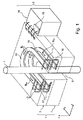
図1は、導線3中を流れる電流の強度を測定するようになっている電流センサ2を示す。 FIG. 1 shows a current sensor 2 that is adapted to measure the intensity of a current flowing through a conductor 3.
電流センサ2は、複数のプリント基板から成り、かつ孔5を形成されている重畳体4を有している。孔5は、垂直な方向Zに沿って、この重畳体4を上面から下面まで突き抜けている。
The current sensor 2 has a superposed
導線3は、孔5中に受容されている。この受容を可能にするために、孔5の横方向寸法、すなわち水平な平面内の寸法(孔5の断面が円形である場合には内径)は、通常、導線3の横方向寸法(導線3の断面が円形である場合には外径)より、少なくとも100μmだけ大きい。
The conducting wire 3 is received in the
図1においては、重畳体4は、2つのプリント基板6および7を、方向Zに沿って重ね合わせたスタックによって作られている。これらのプリント基板は、全く自由度なしに、上下に互いに固着されている。これらのプリント基板を構成している各構成要素を示すように、プリント基板の輪郭は、破線によって示してある。
In FIG. 1, the
プリント基板6は、電気絶縁層によって物理的に互いに分離されている複数のメタライズ層の、方向Zに沿うスタックを有している。このプリント基板6の各層は、互いに直交している2つの方向XおよびYと平行に、水平に延在している。 The printed circuit board 6 has a stack along the direction Z of a plurality of metallized layers that are physically separated from each other by an electrical insulating layer. Each layer of the printed circuit board 6 extends horizontally in parallel with two directions X and Y orthogonal to each other.
プリント基板6は、孔5を囲んでいる磁心を有している。この磁心は、実質的に水平な平面上に延在している磁性体リング10である。
The printed circuit board 6 has a magnetic core surrounding the
電流センサ2の感度を良好にするために、磁性体リング10は、1000を超過し、好ましくは10000を超過する静的な比透磁率、すなわち周波数0Hzにおける比透磁率を有する磁性材料で作られている。すなわち、磁性体リング10は、大きな比透磁率を有する磁性材料で作られている。この磁性材料は、例えばミューメタルなどの強磁性体材料、または「Vitrovac」(登録商標)6025という商品名で知られている磁性材料である。
In order to improve the sensitivity of the current sensor 2, the
磁性体リング10の中心は、孔5の中心に一致していることが好ましい。
The center of the
周波数fexで励磁電流iexを流すための励磁コイル12が、磁性体リング10を囲んでいる。励磁コイル12は、磁性体リング10を周期的に飽和磁化させる励磁磁界Bexを、磁性体リング10の内部に発生させる。
励磁コイル12は、磁性体リング10の全長にわたって延在していることが好ましい。図1において、「磁性体リング10の長さ」は、水平な平面上の、磁性体リングの周の長さを意味している。励磁コイル12の各ターンは、磁性体リング10の内側を通っている。図1を単純化するために、励磁コイル12の1つのターンしか示していない。
The
プリント基板6は、さらに、磁性体リング10の内部の磁界の強度を測定するための測定コイル13を有している。測定コイル13は、励磁コイル12を囲んでいる。図1を単純化するために、測定コイル13の2つのターンしか示されていない。各ターンは、磁性体リング10の中心付近を通っている。測定コイル13は、磁性体リング10の全長にわたって延在している。以下の説明において、測定コイル13による測定値は、関係式(M1=Bi+Bex)によって与えられる。この関係式において、
・ M1は、測定コイル13による測定値であり、
・ Biは、導線3中を流れる電流iによって発生する磁界であり、
・ Bexは、励磁磁界である。
The printed circuit board 6 further includes a measurement coil 13 for measuring the strength of the magnetic field inside the
M 1 is a measured value by the measuring coil 13,
B i is a magnetic field generated by the current i flowing through the conductor 3,
Bex is an exciting magnetic field.
この関係式を導くために、磁性体リング10の内部の磁界の符号は、その磁界が反時計回りの向きに回っているときに正としている。
In order to derive this relational expression, the sign of the magnetic field inside the
磁性体リングを用いることによって、プリント基板6の全表面にわたって一様である外部磁界の影響を自動的に打ち消すことができる。この場合に、「打ち消す」は、電流iの強度の測定の際に、外部磁界の影響を取り除く、または大幅に減らす作用を意味している。磁性体リングを用いることによって、例えば地球磁界の影響を自動的に打ち消すことができる。 By using the magnetic ring, it is possible to automatically cancel the influence of the external magnetic field that is uniform over the entire surface of the printed circuit board 6. In this case, “cancel” means an action of removing or greatly reducing the influence of the external magnetic field when measuring the intensity of the current i. By using the magnetic ring, for example, the influence of the earth's magnetic field can be canceled out automatically.
プリント基板7は、励磁コイルが逆向きに形成されているということを除いて、水平な平面に関して、プリント基板6に面対称である。プリント基板7の磁性体リング、励磁コイルおよび測定コイルには、それぞれ符号15、16および17を付してある。励磁コイル16には、励磁コイル12に供給される励磁電流と同じ励磁電流iexが供給される。このような状態においては、測定コイル17による測定値は、関係式(M2=Bi−Bex)によって与えられる。この関係式において、M2は、測定コイル17による測定値である。
The printed circuit board 7 is symmetrical with respect to the printed circuit board 6 with respect to a horizontal plane, except that the exciting coils are formed in the opposite direction.
この例においては、励磁磁界Bexの寄与を自動的に打ち消すために、測定コイル13と17とは、互いに直列に接続されている。この場合には、「打ち消す」は、最終結果すなわち電流の測定値に対する、励磁磁界Bexの影響または寄与を最大限に取り除くことを意味している。すなわち、この例で用いられている符合の取り決めでは、測定コイル13と17とは、測定値M1とM2とが互いに加え合わされるように接続されている。 In this example, in order to cancel the contribution of the excitation field B ex automatically, the measuring coil 13 and 17 are connected in series with each other. In this case, "cancel" is for measurement of the final result or current, which means removing the most of the effect or contribution of the excitation field B ex. In other words, in the code convention used in this example, the measurement coils 13 and 17 are connected such that the measured values M 1 and M 2 are added together.
電流センサ2は、さらに、有線リンクを介して重畳体4に接続されている電子処理ユニット18を有している。この電子処理ユニット18は、導線3中を流れる電流iの強度値を算出するために、測定コイル13および17から得られた測定値を処理する。電子処理ユニット18は、さらに、励磁コイル12および16に流す励磁電流iexを発生させるようになっている電流源19を有している。
The current sensor 2 further includes an
図2は、電流センサ2の製造に用いられるプリント基板6を、より詳細に示している。図2は、このプリント基板6の内部に埋め込まれているものを詳細に示すために、プリント基板6の断面を示している。 FIG. 2 shows the printed circuit board 6 used for manufacturing the current sensor 2 in more detail. FIG. 2 shows a cross section of the printed circuit board 6 in order to show in detail what is embedded in the printed circuit board 6.
プリント基板6は、多層プリント基板である。したがって、プリント基板6は、電気絶縁層によって互いに分離されている複数のメタライズ層の、垂直方向(方向Z)に沿うスタック20によって形成されている。図2においては、1つの電気絶縁層26によって互いに分離された2つのメタライズ層22および24しか示されていない。このスタック20に関しては、図3以下を参照して、より詳細に説明する。
The printed circuit board 6 is a multilayer printed circuit board. Therefore, the printed circuit board 6 is formed by a stack 20 along the vertical direction (direction Z) of a plurality of metallized layers separated from each other by an electrical insulating layer. In FIG. 2, only two metallized
電気絶縁層26の内部に、磁性体リング10を収容するための空洞28が穿たれている。空洞28の詳細が、図2Aの、プリント基板6の拡大部分断面図に、より明瞭に示されている。この例においては、空洞28は環状である。空洞28は、2つのメタライズ層22と24との間に位置している。この空洞28には、垂直対称軸30が存在する。垂直対称軸30は、孔5の垂直対称軸でもある。この空洞28は、矩形の横断面を有している。この横断面とは、垂直対称軸30を含む垂直面に含まれる断面である。より明確には、空洞28は、外側垂直壁32、内側垂直壁33、水平な上端34、および水平な下端36を有している。外側垂直壁32および内側垂直壁33は、環状である。空洞28の横断面は、空洞28の全長にわたって一定である。空洞28の長さとは、水平な平面上の、空洞28の周の長さ、例えば内側垂直壁33の周の長さである。
A
磁性体リング10が、空洞28の内部に収容されている。磁性体リング10の回転対称軸は、垂直対称軸30と一致している。磁性体リング10の横断面も矩形である。さらに、磁性体リング10の横断面は、磁性体リング10の全長にわたって一定である。
The
静的な比透磁率を大きくするために、磁心すなわち磁性体リング10の、方向Zに沿う厚さeは、可能な限り薄くされる。磁性体リング10の厚さは、通常、例えば250μm未満であり、好ましくは125μm未満、または25μm未満である。磁性体リング10の、半径方向の幅Iは、通常、0.5〜10mmの範囲にある。この例においては、幅Iは、例えば1〜2mmの範囲にある。
In order to increase the static relative permeability, the thickness e of the magnetic core, that is, the
この磁性体リング10は、例えば重力の作用だけで、空洞28の下端36に接している下面を有している。磁性体リング10は、さらに、空洞28の上端34に対向している上面40、および外側垂直壁32、内側垂直壁33にそれぞれ対向している外側垂直面、および内側垂直面を有している。
The
磁性体リング10の横断面の寸法は、空洞28の横断面の対応する寸法よりも小さい。したがって、磁性体リング10の幅Iおよび厚さeは、それぞれ空洞28の幅および厚さ未満である。これによって、磁性体リング10の外側垂直面および内側垂直面を、それぞれ外側垂直壁32および内側垂直壁33から、横方向に間隙iだけ離すことができ、磁性体リング10の上面40を、上端34から、垂直方向に間隙jだけ離すことができる。間隙iおよびjは、5μmを超過しており、好ましくは100μmを超過している。したがって、このような状態においては、空洞28は、磁性体リング10になんらの機械的応力も及ぼさない。磁性体リング10が機械的応力を受けないことによって、磁性体リング10の磁気特性の変動が制限されるから、電流センサ2の精度が増す。
The dimension of the cross section of the
プリント基板6は、さらに、励磁コイル12および測定コイル13を有している。図2には、単純化のために、励磁コイル12のターンしか示されていない。これらのターンは、例えば磁性体リング10の全長にわたって、一定の間隔で一様に配置されている。
The printed circuit board 6 further includes an
励磁コイル12の各ターンの構成要素として、次のものが含まれる。
− メタライズ層22に形成されている導電トラック44のうちの1つと、
− メタライズ層24に形成されている導電トラック46のうちの1つ。
The constituent elements of each turn of the
One of the
One of the
各ターンには、さらに、そのターンの導電トラック44と46との一端同士を電気的に接続している垂直ビア48が含まれる。さらに、そのターンの導電トラック44と46との他端は、それぞれ別の垂直ビアを介して、それぞれに隣接するターンの導電トラックの一端に電気的に接続されている。
Each turn further includes a vertical via 48 that electrically connects one end of the
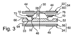
図3は、プリント基板6の第1の実施形態の分解組立図である。この実施形態においては、スタック20は、底から頂に向かって、次のものをスタックすることによって形成されている。
− メタライズされたプリプレグ50と、
− 電気絶縁層52と、
− メタライズされたプリプレグ54。
FIG. 3 is an exploded view of the printed circuit board 6 according to the first embodiment. In this embodiment, the stack 20 is formed by stacking the following from bottom to top.
-A
-An electrically insulating
-
メタライズされたプリプレグ50には、プリプレグ56と、プリプレグ56の下面に固着されているメタライズ層24とが含まれている。
The metallized
メタライズされたプリプレグ54には、プリプレグ60と、プリプレグ60の上面に固着されているメタライズ層22とが含まれている。
The metallized
この例においては、プリプレグ56および60は、「規格」仕様のプリプレグ、すなわちプリント基板のアセンブリ時に低粘度を呈するプリプレグである。「低粘度」は、プリプレグのメーカの仕様に応じた上昇率で、そのプリプレグの温度を上昇させていくときに、ガラス転移温度において、5000パスカル秒未満、好ましくは1000パスカル秒未満である粘度を意味している。 In this example, prepregs 56 and 60 are "standard" specification prepregs, i.e., prepregs that exhibit a low viscosity upon assembly of a printed circuit board. “Low viscosity” refers to a viscosity that is less than 5000 Pascal seconds, preferably less than 1000 Pascal seconds at the glass transition temperature when the temperature of the prepreg is increased at an increase rate according to the specifications of the prepreg manufacturer. I mean.
プリプレグ56および60は、例えば次の材料、すなわちFR−2(コットン紙・フェノール樹脂)、FR−3(コットン紙・エポキシ樹脂)、FR−4(布状に編んだガラス繊維・エポキシ樹脂)、FR−5(布状に編んだガラス繊維・エポキシ樹脂)、FR−6(ガラス塗膜・ポリエステル樹脂)、G−10(布状に編んだガラス繊維・エポキシ樹脂)、CEM−1(コットン紙・エポキシ樹脂)、CEM−2(コットン紙・エポキシ樹脂)、CEM−3(布状に編んだガラス繊維・エポキシ樹脂)、CEM−4(布状に編んだガラス繊維・エポキシ樹脂)、CEM−5(布状に編んだガラス繊維・ポリエステル樹脂)のうちの1つを用いて製造することができる。この例においては、プリプレグ56および60は、アーロン〔Arlon(登録商標)〕社から販売されている参照コード33Nの製品群から選択されたプリプレグ(例えば参照コード33N2355のプリプレグ)である。
The
電気絶縁層52は、本明細書の導入部で説明されているような電気絶縁層である。電気絶縁層52は、例えば規格で定められているFR−4から成っている。電気絶縁層52の下面64は、プリプレグ56と対向しており、上面66は、プリプレグ60と対向している。プリプレグ56および60は、それぞれ電気絶縁層52の下面64および上面66を完全に覆っている。さらに、プリプレグ56および60は、それぞれ電気絶縁層52の下面64および上面66に、直接に配置されている。すなわち、他の層の介在なしに密着している。
The
空洞28は、電気絶縁層52の上面66から、その内部に向かって穿たれている。したがって、この空洞28は、上面66に開いている口部を有している。この口部には、空洞28の外側垂直壁32および内側垂直壁33の上部で、それぞれ棚部70および72が形成されている。これらの棚部70および72の深さは、関係式(p=h−e−j)によって与えられる。この関係式において、
・ pは、棚部70および72の深さであり、
・ hは、上面66からの空洞28の深さであり、
・ eは、磁性体リング10の厚さであり、
・ jは、磁性体リング10と空洞28の上端34(棚部70および72の下端)との間の垂直方向の間隙である。
The
P is the depth of the
H is the depth of the
E is the thickness of the
J is the vertical gap between the
深さpおよびhは、方向Zにおけるものである。 Depths p and h are in direction Z.
プリント基板6は、さらに、特にプリント基板のアセンブリ時のクリープ変形によって、プリプレグ60が、磁性体リング10上に達することを防止するための抗クリープ手段を構成しているカバー76を備えている。この防止のために、この例においては、カバー76は、垂直対称軸30と一致する回転対称軸を有する環状リングの形状を有している。このカバー76の内縁および外縁は、それぞれそれらが棚部72および70上に載るような寸法に定められている。したがって、プリント基板がアセンブルされたときに、このカバー76は、磁性体リング10を圧迫せず、したがって、磁性体リング10になんらの機械的応力も及ぼさない。
The printed circuit board 6 further includes a
カバー76の厚さは、棚部70および72の深さp以下である。カバー76の厚さは、例えば最大で、深さpより10%だけ小さい。したがって、プリント基板がアセンブルされたときに、カバー76は、上面66よりも上に突き出ることはない。
The thickness of the
カバー76は、剛性材料、すなわち2GPaを超過し、好ましくは、10GPaまたは100GPaを超過するヤング率を有する材料を用いて製造されている。本明細書においては、ヤング率は、20℃の温度における値として与えられる。カバー76は、例えばFR−4を用いて製造される。カバー76は、例えば剛体板からの切り出しによって製造される。カバー76は、非磁性体材料、すなわち静的な比透磁率が1である材料を用いて製造される。
The
図4は、図3のプリント基板を、アセンブルされた状態で示している。さらに、図4においては、導電トラック44と導電トラック46とを接続している垂直ビア48が示されている。プリント基板がアセンブルされると、電気絶縁層52、およびプリプレグ56、および60の重畳体が、プリント基板の電気絶縁層26を構成する。
FIG. 4 shows the printed circuit board of FIG. 3 in an assembled state. Further, in FIG. 4, a vertical via 48 connecting the
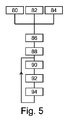
次に、プリント基板6の製造方法を、図5のフローチャートを参照して説明する。 Next, a method for manufacturing the printed circuit board 6 will be described with reference to the flowchart of FIG.
ステップ80において、電気絶縁層52の機械加工により、電気絶縁層52に空洞28が形成される。
In
これと並行して、ステップ82において、電気絶縁層52の機械加工から独立して、磁性体リング10が製造される。磁性体リング10は、例えば磁性体材料のシートから切り出して製造される。
In parallel with this, in
ステップ80および82と並行して、ステップ84において、電気絶縁層52および磁性体リング10の製造から独立して、カバー76も製造される。カバー76は、例えば非磁性体材料の剛性ボードから切り出して製造される。
In parallel with
次に、ステップ86において、磁性体リング10が、空洞28内に挿入される。
Next, in
ステップ88において、カバー76が、空洞28の棚部70および72上に配置される。
In
ステップ90において、メタライズ層のアセンブリングが行われる。このアセンブリングのために、この実施形態においては、メタライズされたプリプレグ50および54が、それぞれ電気絶縁層52の下面64および上面66に対向するように配置される。次に、プリプレグ56および60に熱硬化が生じるように、メタライズされたプリプレグ50および54は、150℃以上の温度に加熱され、同時に、方向Zに沿って重ねられた電気絶縁層52、およびメタライズされたプリプレグ50および54に、1MPaを超過する垂直圧力が印加される。このステップ90において、プリプレグ56および60は、重合によって、最終的に、メタライズ層を備えて、電気絶縁層52の下面64および上面66に接合された剛性物質に変換される。
In
ステップ90において、プリプレグ60は、クリープ変形する。しかしながら、カバー76の作用によって、プリプレグ60の、磁性体リング10への到達と、それによる、磁性体リング10の熱膨張方向と異なる熱膨張方向を有する混合物の形成が防止される。
In
ステップ92において、導電トラック44および46が、それぞれメタライズ層22および24に作り出される。これらの導電トラックは、例えばメタライズ層のエッチングによって作り出される。
In
次いで、ステップ94において、各導電トラックを電気的に接続して、励磁コイル12を形成するためのビアが作り出される。ビアは、例えば導電トラック44および46、プリプレグ60および56、および電気絶縁層52を貫通する貫通孔を穿設した後、そのようにしてできた貫通孔の内壁をメタライズすることによって作り出される。
Next, in
スタック中に、さらなるメタライズ層(導電トラックおよびビア)を加えるために、ステップ90、92、および94を繰り返すことができる。
図6は、プリント基板6の別の一実施形態を示しており、棚部70および72が省かれている。このような状態において、カバー76に替えて、空洞28の内部に収容されるようになっている寸法を有しているカバー100が用いられている。この実施形態においては、カバー100は、磁性体リング10に物理的に接しているが、磁性体リング10の熱膨張方向と異なる熱膨張方向を有する混合物を形成しない。
FIG. 6 shows another embodiment of the printed circuit board 6 where the
図7は、プリント基板6の別の一実施形態の分解組立図である。この実施形態は、電気絶縁層52に替えて、電気絶縁層102が用いられており、カバー76に替えて、カバー104が用いられていることを除いて、図3を参照して説明した実施形態と同一である。
FIG. 7 is an exploded view of another embodiment of the printed circuit board 6. In this embodiment, the electric insulating
電気絶縁層102は、空洞28に囲まれている、電気絶縁層52の中心部が、電気絶縁層102を垂直に貫いている孔に置き換えられていることを除いて、電気絶縁層52と同一である。
The
カバー104は、電気絶縁層102の、孔になっている中心部に嵌まり込む部分が、カバー104に組み込まれているということを除いて、カバー76と同一である。したがって、カバー104は、電気絶縁層102の孔に嵌まり込むようになっている中心部を有する円板の形状を呈している。
The
図8は、図7の実施形態を、アセンブルされた状態で示している。 FIG. 8 shows the embodiment of FIG. 7 in an assembled state.
図9は、図8のプリント基板の外側下面上および外側上面上に、別の、メタライズされたプリプレグ110および112がスタックされているプリント基板を示している。したがって、これは、2つのメタライズ層を加えることを可能にする例である。この例においては、追加のメタライズ層から、垂直ビア119を介して互いに電気的に接続される2つの導電トラック114および116が作り出され、例えば測定コイル13のターンを形成するために用いられる。
FIG. 9 shows a printed circuit board on which another metallized
図10は、プリント基板の別の一実施形態を示している。この実施形態は、空洞28の棚部が省かれているということを除いて、図7の実施形態と同じである。図10において、電気絶縁層およびカバーには、それぞれ参照符号120および122を付してある。
FIG. 10 shows another embodiment of the printed circuit board. This embodiment is the same as the embodiment of FIG. 7 except that the shelf of the
図11は、プリント基板6の別の一実施形態を示している。この実施形態は、いかなるメタライズされたプリプレグも用いずに、メタライズされた電気絶縁層を用いているということを除いて、図3を参照して説明した実施形態と同じである。より詳細には、メタライズされたプリプレグ50および電気絶縁層52に替えて、メタライズされた電気絶縁層124が用いられている。メタライズされた電気絶縁層124は、下面にメタライズ層24が固着された電気絶縁層126を有している。メタライズされたプリプレグ54に替えて、メタライズ層22と電気絶縁層132とから成る、メタライズされた電気絶縁層130が用いられている。メタライズされた電気絶縁層130と124とは、電気絶縁層126の上面全体を覆っているプリプレグ134を介して、互いにアセンブルされている。
FIG. 11 shows another embodiment of the printed circuit board 6. This embodiment is the same as the embodiment described with reference to FIG. 3 except that it uses a metallized electrical insulating layer without any metallized prepreg. More specifically, a metallized electrical insulating
プリント基板6のこの実施形態の製造方法は、ステップ90において、メタライズされた電気絶縁層124と130との一体化のために、それらの間にプリプレグ134が挿入されるということを除いて、図5を参照して説明した実施形態の製造方法と同じである。
The manufacturing method of this embodiment of the printed circuit board 6 is similar to that shown in
図12は、プリント基板6の別の一実施形態を示している。この実施形態は、カバー76に替えてカバー140が用いられていることを除いて、図6を参照して説明した実施形態と同じである。カバー140は、軟質材料、すなわち0.1GPa未満のヤング率を有する材料を用いて作られている。
FIG. 12 shows another embodiment of the printed circuit board 6. This embodiment is the same as the embodiment described with reference to FIG. 6 except that a
この実施形態においては、磁性体リング10上へのカバーの挿入は、空洞28内で磁性体リング10上に軟質材料を流し込むことによって行われる。軟質材料が流し込まれるとき、この軟質材料の粘度は、軟質材料が、磁性体リング10にいかなる機械的応力も及ぼさずに、間隙iおよびjを完全に満たすことができるほどに十分に低い。通常、カバー140を形成するために用いられる材料は、非熱硬化性の軟質樹脂である。さらに、選ばれる軟質樹脂は、プリント基板の製造温度に耐えることができなければならない。この軟質樹脂は、例えばシリコーンである。したがって、カバー140のこの材料の剛性は、磁性体リング10にいかなる機械的応力も及ぼすことがないほどに、また温度変化に応答して磁性体リング10の変形をもたらす可能性が高い、磁性体リング10の熱膨張方向と異なる熱膨張方向を有する混合物を形成しないほどに十分に低い。カバー140が空洞28内に流し込まれてしまうと、その後の製造ステップは、図5を参照して説明した製造ステップと同じである。
In this embodiment, the cover is inserted onto the
図13は、カバー100が省かれているということを除いて、図6のプリント基板と同じプリント基板6の実施形態を示している。メタライズされたプリプレグ54に替えて、メタライズされたプリプレグ150が用いられている。メタライズされたプリプレグ150は、プリプレグ60に替えてプリプレグ152が用いられているということを除いて、メタライズされたプリプレグ54と同じである。プリプレグ152は、同一の条件で測定したときに、プリプレグ60の粘度の少なくとも10倍、好ましくは20倍を超過する、ガラス転移温度における粘度を有している。プリプレグ152は、例えばメーカの仕様に応じた上昇率でプリプレグの温度を上昇させていくときに、ガラス転移温度において10000パスカル秒を超過し、好ましくは20000パスカル秒を超過する粘度を有する熱硬化性樹脂だけから成っている。温度の上昇率は、例えば5℃/分である。プリプレグの粘度は、「ミル」またはミリメートルを測定単位にして測定することもできる。この測定のためには、1インチ(0.03メートル)の直径の孔が、プリプレグに穿たれる。次に、電気絶縁層98が、上述のステップ90において適用されている条件と同じ条件で、このプリプレグにアセンブルされる。このアセンブリ時に、プリプレグはクリープ変形し、孔の直径は減少する。アセンブリ前の孔の直径と、アセンブリ後の孔の平均直径との間の差が、プリプレグの粘度の測定値をなす。この差は、「ミル」(2.54×10−5メートル)、またはミリメートルを単位として表わされる。この方法によって測定される、プリプレグ152の粘度は、通常、3.5mm未満、好ましくは2mm未満または1.5mm未満である。プリプレグ152は、例えばアーロン社によって販売されている、参照コード37Nの製品群から選択される1つのプリプレグである。プリプレグ152は、例えば参照コード37N0666を付けられているプリプレグである。
FIG. 13 shows an embodiment of the same printed circuit board 6 as that of FIG. 6 except that the
このようなプリプレグは、「ノーフロープリプレグ」という名称で知られている。プリプレグ152は、抗クリープ手段を構成している。実際、アセンブリ時においても、プリプレグ152の粘度が非常に高ければ、プリプレグ152は、カバーがない状態においても、磁性体リング10まで達することはできない。
Such a prepreg is known by the name “no-flow prepreg”. The
この実施形態の製造方法は、カバーの製造、およびこのカバーの載置が不必要であるということを除いて、図5を参照して説明した製造方法と同じである。 The manufacturing method of this embodiment is the same as the manufacturing method described with reference to FIG. 5 except that the manufacture of the cover and the placement of the cover are unnecessary.
図14は、プリプレグ134に替えてプリプレグ160が用いられているということを除いて、図11を参照して説明したプリント基板と同じプリント基板6の実施形態を示している。プリプレグ160は、例えばプリプレグ152と同様のノーフロープリプレグである。このような条件の下では、アセンブリ時に、このプリプレグ160の高い粘度が維持されるために、このプリプレグ160は、磁性体リング10まで達しないから、カバー76を省くことができる。
FIG. 14 shows an embodiment of the same printed circuit board 6 as the printed circuit board described with reference to FIG. 11 except that a
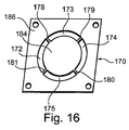
図15の実施形態は、カバー76および棚部が省かれているということ、およびプリプレグ134に替えてプリプレグ170が用いられているということを除いて、図11の実施形態と同じである。プリプレグ170は、図16に、より詳細に示されている。プリプレグ170は、アセンブリ時に、空洞28の口部に対向しているように形成されている開口を有していることを除いて、プリプレグ134と同じである。この例においては、プリプレグ170は、例えば垂直対称軸30を中心とするリングの一部分の形状を各々に有している、4つの開口172〜175を備えている。
The embodiment of FIG. 15 is the same as the embodiment of FIG. 11 except that the
これらの開口172〜175の各々の横方向の幅は、メタライズされた電気絶縁層124の上面66における、空洞28の口部の横方向幅にオフセットマージンを加えた大きさに等しい。オフセットマージンの大きさは、アセンブリ時に、プリプレグ170が空洞28の口部の縁まで広がらないように定められる。したがって、アセンブリ前には、開口172〜175の端は、空洞28の口部の縁に対して、半径方向に距離Rだけずれている。距離Rの大きさは、アセンブリ時に、プリプレグ170が磁性体リング10まで達することができないように、例えば試行錯誤によって定められる。距離Rは、例えば100μm以上であり、200μm以上または300μm以上または1mm以上であることが好ましい。したがって、これらの開口172〜175は、抗クリープ手段を構成している。
The lateral width of each of these openings 172-175 is equal to the lateral width of the mouth of the
プリプレグ170は、さらに、プリプレグ170の中心部184と、プリプレグ170の周辺部186とを物理的に接続するために、垂直対称軸30のまわりに一様な間隔で分配されている複数のブリッジ部178〜181を有している。これらのブリッジ部178〜181の幅は、それらの総表面積が、磁性体リング10の上面の表面積の20%未満、好ましくは10%未満、または5%未満であるように定められる。
The
このような状態においては、これらのブリッジ部が、アセンブリ時に、磁性体リング10に達するほどにクリープ変形したとしても、それを被る、磁性体リング10の表面積は非常に小さく、電流センサ2の正常な動作を著しく乱すような機械的応力が生み出されることはない。
In such a state, even if these bridge portions are creep-deformed enough to reach the
図17は、プリント基板6の代わりに用いることができるプリント基板178を示している。このプリント基板178は、磁性体リング10に替えて、2つの磁性体バー180および182が用いられているということを除いて、プリント基板6と同じである。したがって、プリント基板178は、上述のような抗クリープ手段を備えている。これらの磁性体バーは、平行六面体の形状を呈しており、Y方向に沿って、互いに平行に配置されている。理解を容易にするために、図17においては、磁性体バー180および182は、プリント基板178から突き出ているように示されているが、実際には、それらの磁性体バーは、プリント基板178の内部に完全に収容されている。磁性体バー180および182の厚さおよび幅は、例えば磁性体リング10の厚さおよび幅に等しい。磁性体バー180および182の、Y方向に沿う長さは、通常、5〜60mmの範囲にある。磁性体バー180および182の各々を、励磁コイルおよび測定コイルが囲んでいる。これらの励磁コイルおよび測定コイルは、前述のプリント基板6の場合と同様に形成される。図17において、励磁コイルの上側導電トラックおよび下側導電トラックに、それぞれ参照符号184および186を付している。図の単純化のために、測定コイルおよび電子処理ユニット18は示していない。
FIG. 17 shows a printed
プリント基板178を用いて製造される電流センサの動作は、電流センサ2の動作と同様である。しかしながら、磁性体リングではなく磁性体バーを用いているために、この電流センサは、占有面積を小さく保ちながら、より高強度の電流を測定することができる。
The operation of the current sensor manufactured using the printed
図18は、プリント基板178の製造方法を説明するフローチャートである。
FIG. 18 is a flowchart for explaining a method for manufacturing the printed
この製造方法は、磁性体リング10に替えて2つの磁性体バーが用いられるということ、およびアセンブリ時に仮ブロックが用いられるということを除いて、図5を参照して説明した製造方法と同じである。
This manufacturing method is the same as the manufacturing method described with reference to FIG. 5 except that two magnetic bars are used instead of the
より詳細には、ステップ84に替えて、磁性体バー180および182の寸法以上であり、かつ磁性体バー180および182が収容される空洞28の寸法未満である寸法を有する2つの仮ブロック191(図19)を製造するステップ190が用いられる。
More specifically, in place of
ステップ86に替えて、磁性体バー180、182の代わりに、仮ブロックが1つずつ各空洞に挿入されるステップ192が用いられる。
Instead of
次に、ステップ90、92、および94が実行される。3つ以上のメタライズ層をスタックするために、これらのステップ90、92、および94を繰り返すことができる。
Next, steps 90, 92 and 94 are executed. These
ステップ94が完了すると、ステップ196において、仮ブロック191が、磁心となる磁性体バー180および182に交換される。この交換のために、プリント基板178の一端が切断されて、仮ブロック191が収容されている各空洞の一端が外部に向かって開放される。この状態が、図19に示されている。次に、各仮ブロック191が、各空洞の開放された端から引き出される。この状態が、図20に示されている。次いで、磁性体バー180および182が、磁心として、各空洞の開放された端から、各空洞内に挿入される(図21)。
When
図19〜図21は、図16を参照して説明したような抗クリープ手段を備える特定の一例を示している。すなわち、この例においては、抗クリープ手段は、くり抜きプリプレグ198である。このくり抜きプリプレグ198には、磁心を構成している磁性体バー180および182に達することのないように、各空洞に対向する開口が形成されている。
19 to 21 show a specific example including anti-creep means as described with reference to FIG. That is, in this example, the anti-creep means is a
図22は、磁界センサ200を示している。磁界センサ200は、精密な磁界センサである、すなわちノイズのパワースペクトル密度の二乗平均平方根(頭字語RMS PSDとも呼ばれる)が、1nT/√(Hz)未満または100pT/√(Hz)未満であり、ある種の構成においては10pT√(Hz)未満である磁界センサである。
FIG. 22 shows the
この例においては、磁界センサ200は、「フラックスゲート」センサとして広く知られている磁界センサである。このような磁界センサの動作はよく知られており、したがって、本明細書においては詳細に説明しない。フラックスゲートセンサの動作に関する説明としては、例えば特許文献7を参照されたい。
In this example, the
以下において、磁界センサ200の、本発明についての理解に必要な要素だけを説明する。
Only the elements of the
この例においては、磁界センサ200は、連続磁界すなわち静磁界を測定するために用いられる。この連続磁界は、例えば地球磁界である。
In this example, the
磁界センサ200は、外部磁界Tの方向を、さらに、必要に応じて、その強度を測定することができる。より具体的には、磁界センサ2は、外部磁界Tの、同一直線上にない3つの方向X、Y、Zへの投影にそれぞれ一致する外部磁界成分TX、TY、TZを測定する。この例においては、方向X、Y、Zは、互いに直交している。方向Zは垂直方向であり、方向XおよびYは、水平な平面を定めている。
The
磁界センサ200は、多層プリント基板204を備えている。多層プリント基板204は、通常、5層を超えるメタライズ層、好ましくは10層を超えるメタライズ層を有している。この例においては、多層プリント基板204は、10層のメタライズ層を有している。メタライズ層は、方向Zに沿って、上下にスタックされている。方向Zにおける最も上のメタライズ層は、多層プリント基板204の上面と一致し、一方、最も下のメタライズ層は、多層プリント基板204の下面と一致している。
The
多層プリント基板204は、水平な環状の空洞内に収容された磁性体リング206を有している。磁性体リング206は、多層プリント基板204の上面と下面との間に位置している。この多層プリント基板204は、プリント基板6の場合に対して前述したようにして製造される。したがって、多層プリント基板204は、特に、前述の抗クリープ手段の1つを備えている。次に、プリント基板6に対する、多層プリント基板204の主な相違点のみを特に説明する。
The multilayer printed
磁性体リング206は、方向Xに平行に2つの磁性体バー208および209、方向Yに平行に2つの磁性体バー211および212を有している。これらの磁性体バーの端部は、磁性材料から成るコーナー部によって互いに連結されており、全体として、磁性体リング206を形成している。
The
磁性体リング206を飽和磁化させるための、4つの励磁コイル214〜217が、多層プリント基板204内に形成されている。これらの励磁コイルは、励磁周波数fHで、励磁電流i0Hを流される。励磁周波数は、通常、300Hzを超過するが、10kHzを超過することが好ましい。図22の場合には、励磁コイル214〜217は、それぞれ磁性体バー211、208、212、209を囲んでいる。
Four
励磁コイル214〜217に励磁電流i0Hが流されたときに、一方の向きに、励磁磁界BexHが発生するように、励磁コイル214〜217は、互いに直列に接続されている。各励磁コイル214〜217は、磁性体リング206の上側および下側にそれぞれ1層ずつ位置している、多層プリント基板204の2層のメタライズ層に形成されている導電トラックを主要な構成要素としている。導電トラックの端部は、垂直ビアによって互いに連結されている。これによって、磁性体リング206の上側と下側とに位置しているメタライズ層が連続的に結合されて、励磁コイル214〜217の各々の各ターンが形成されている。
The excitation coils 214 to 217 are connected in series so that the excitation magnetic field B exH is generated in one direction when the excitation current i 0H is passed through the excitation coils 214 to 217. Each of the
多層プリント基板204は、さらに、磁性体バー211、208、212、209の内部の磁界を測定するために、それらの磁性体バーを、それぞれ1つずつ囲んでいる4つの測定コイル220〜223を有している。これらの測定コイル220〜223の各々による磁界の測定値を、それぞれM1、M2、M3、M4とする。これらの測定値は、次の関係式によって与えられる。
・ M1=TY−BexH
・ M2=TX+BexH
・ M3=TY+BexH
・ M4=TX−BexH
In order to measure the magnetic field inside the
M 1 = T Y −B exH
M 2 = T X + B exH
M 3 = T Y + B exH
M 4 = T X -B exH
これらの関係式は、次の条件の下におけるものである。すなわち、励磁磁界Bexは、反時計回りの向きに回っており、外部磁界成分TXおよびTYは、それぞれ方向XおよびYと同じ方向に向いている。 These relational expressions are under the following conditions. That is, the excitation magnetic field B ex rotates counterclockwise, and the external magnetic field components T X and T Y are directed in the same direction as the directions X and Y, respectively.
測定コイル220〜223は、それぞれ励磁コイル214〜217を囲んでいる。これらの測定コイル220〜223は、励磁コイル214〜217の導電トラックを形成するために用いられているメタライズ層の上側および下側に位置しているメタライズ層に形成されている導電トラックを、主な構成要素としている。 The measurement coils 220 to 223 surround the excitation coils 214 to 217, respectively. These measurement coils 220 to 223 mainly include conductive tracks formed on the metallized layers located above and below the metallized layer used to form the conductive tracks of the excitation coils 214 to 217. As a component.
この実施形態においては、さらに、4つの補償コイル226〜229が、それぞれ測定コイル220〜223を囲んでいる。補償コイル226〜229は、それぞれ磁性体バー211、208、212、209内の磁界を打ち消すことができる。このような状態においては、外部磁界成分TXおよびTYの測定値は、補償コイル226〜229に流れる補償電流icHの強度から演繹される。
In this embodiment, four compensation coils 226-229 further surround the measurement coils 220-223, respectively. The compensation coils 226 to 229 can cancel the magnetic fields in the
補償コイル226〜229は、測定コイルの導電トラックを形成するために用いられているメタライズ層の上側および下側に位置しているメタライズ層に形成されている導電トラックを主な構成要素としている。 The compensation coils 226 to 229 are mainly composed of conductive tracks formed on the metallized layers located above and below the metallized layer used to form the conductive tracks of the measurement coil.
この例においては、測定は、ゼロ磁界状態においてなされるから、方向XとYとに沿って測定される測定値間に生じる磁気結合は、ゼロ磁界状態とせずに、同一の磁性体リング206を、方向XとYとに沿って囲んでいる2つの測定コイルを用いて測定を行う場合に比して減少する。
In this example, since the measurement is performed in the zero magnetic field state, the magnetic coupling between the measured values measured along the directions X and Y does not cause the zero magnetic field state, and the same
多層プリント基板204は、さらに、外部磁界成分TZを測定するための垂直コイルを有している。用語「垂直コイル」は、垂直軸を囲んで、垂直軸に沿って延在しているコイルを意味している。
Multilayer printed
より具体的には、それぞれ垂直軸234および236に沿って、多層プリント基板204を貫通している2つの孔230および232が、多層プリント基板204に穿たれている。これらの孔230および232は、垂直磁性体リングの2つのアームの一方および他方をそれぞれ受容するためのものである。単純化するために、この垂直磁性体リングは、図22には示されていない。
More specifically, two
これらの孔230および232の周囲に、多層プリント基板204は、それぞれ垂直励磁コイル238および239を有している。これらの垂直励磁コイルは、励磁周波数fexvの励磁電流iexvを流されたときに、垂直磁性体リングを飽和磁化させることができる励磁磁界Bexvを発生させる。励磁電流iexvおよび励磁周波数fexvは、例えばそれぞれ励磁電流iexHおよび励磁周波数fexHと等しくされる。
Around these
垂直測定コイル240が、2つの孔230および232を囲んでいる。この垂直測定コイル240は、垂直磁性体リング内の磁界を測定するためのものである。
A vertical measuring coil 240 surrounds the two
さらに、垂直補償コイル242が、多層プリント基板204内に形成されている。垂直補償コイル242は、孔230および232を囲んでいる。上述の補償コイル226〜229と同様に、垂直補償コイル242は、それに補償電流icvが流されたときに、垂直磁性体リング内の磁界を打ち消す機能を有している。
Furthermore, a
垂直励磁コイル238および239、垂直測定コイル240、垂直補償コイル242は、多層プリント基板204の各メタライズ層に形成されている各1つの導電トラックによって構成されている。各コイルに属する導電トラック同士が、垂直ビアによって互いに結合されて、各コイルのターンを形成している。
The vertical excitation coils 238 and 239, the vertical measurement coil 240, and the
最後に、磁界センサ200は、励磁コイルおよび補償コイル、垂直励磁コイルおよび垂直補償コイルへの電流供給を制御するように、また外部磁界Tの測定値を得るために、測定コイルおよび垂直測定コイルからの信号を処理するように適合化されている電子処理ユニット250を備えている。通常、外部磁界Tの各外部磁界成分の測定値は、測定コイルまたは垂直測定コイルによって測定される磁界のうちの、励磁周波数の高調波である周波数を有する磁界の振幅から得られる。
Finally, the
他の多くの実施形態が可能である。例えば電気絶縁層を、別様に作り出すことができる。例えば電気絶縁層を、FR−5、G10、またはG11などの規格に合わせることができる。 Many other embodiments are possible. For example, an electrically insulating layer can be created differently. For example, the electrical insulating layer can be adapted to standards such as FR-5, G10, or G11.
ビアを、金属リベットで作ることもできる。 Vias can also be made of metal rivets.
メタライズ層のエッチング以外の技術を用いて、導電トラックを作り出すことができる。例えば電気絶縁層の上に、導電トラックを被着させることもできる。この技術においては、メタライズ層は、内部に導電トラックが被着している層(導電トラックが存在している層)である。 Conductive tracks can be created using techniques other than etching the metallization layer. For example, a conductive track can be deposited on the electrically insulating layer. In this technique, the metallized layer is a layer in which conductive tracks are deposited (layer in which conductive tracks exist).
図7の実施形態において、電気絶縁層102の孔は、貫通孔でない場合がある。
In the embodiment of FIG. 7, the holes in the electrical insulating
本明細書において説明されている抗クリープ手段の各実施形態を、互いに組み合わせることができる。 The anti-creep means embodiments described herein can be combined with each other.
仮ブロックを、いかなる抗クリープ手段を用いるかに関係なく、適用することができる。 The temporary block can be applied regardless of what anti-creeping means is used.
図18のフローチャートは、ステップ196がステップ94の後に行われる、1つの特定の製造方法について説明したものである。しかしながら、ステップ196を、ステップ90、92、94のうちのいずれか1つの後に行うこともできる。
The flowchart of FIG. 18 describes one specific manufacturing method in which step 196 is performed after
単一のコイルで、測定コイルと励磁コイルとの機能の両方を果たすことができる。測定が励磁周波数の高調波周波数においてなされるという事実によって、これが可能になる。この場合には、励磁コイル12および測定コイル13に替えて、例えば単一のコイルが用いられる。単一のコイルで、測定コイルと補償コイルとの機能の両方を果たすこともできる。
A single coil can serve both as a measurement coil and an excitation coil. This is made possible by the fact that measurements are made at harmonic frequencies of the excitation frequency. In this case, for example, a single coil is used instead of the
特許文献7において、図6を参照して説明されているように、励磁コイルのターンと測定コイルのターンとを交互に配置することができる。 In Patent Document 7, as described with reference to FIG. 6, excitation coil turns and measurement coil turns can be alternately arranged.
一変形例として、2つの磁性体リング、およびそれらと組み合わされる測定コイル、および励磁コイルを同一のプリント基板内に作ることができる。この場合には、互いに独立に作られた2つのプリント基板を重ね合わせる必要はない。 As a variant, it is possible to make two magnetic rings and their associated measurement coils and excitation coils in the same printed circuit board. In this case, it is not necessary to superimpose two printed circuit boards made independently of each other.
最後に、単純化された一実施形態において、磁性体リング15、励磁コイル16、および測定コイル17を省くことができる。この場合には、電子処理ユニット18は、測定コイル13から伝達される測定データ中に存在する励磁磁界成分を打ち消すようにプログラムされる。
Finally, in a simplified embodiment, the
磁性体リング10は、導線3によって発生する磁束を最大限に捕捉するように構成される。例えば導線3に替えて、矩形断面の導電バーが用いられる場合には、磁性体リング10に替えて、矩形リングを用いるほうが有利である。
The
孔230、232に収容される垂直磁性体リングを、「U」字形状の2つの磁性体部品を互いに逆向きに組み合わせることによって、または線状または帯状の磁性体を孔230と232との両方を通るように巻くことによって形成することができる。後者の場合には、線状または帯状の磁性体は、孔230および232を通る1つ以上のターンを形成することが好ましい。磁性体リングに替えて、垂直で互いに平行な2つの磁性体バーを用いることもできる。
Perpendicular magnetic rings accommodated in the
図22の実施形態において、いくつかの多層プリント基板を重ね合わせることによって、磁性体リングの(長さ/幅)比、および磁界センサのターン数を増やすことができる。 In the embodiment of FIG. 22, the (length / width) ratio of the magnetic ring and the number of turns of the magnetic field sensor can be increased by overlapping several multilayer printed circuit boards.
一変形例として、導線3を、プリント基板にしっかりと取り付けられている剛性部分を用いて形成することができる。通常、導線3のこの剛性部分は、プリント基板中に作られている垂直の導電トラックである。この垂直の導電トラックは、例えば孔5のメタライゼーションによって作られる。次に、電流の強度の測定を可能にするために、導線3の柔軟性のある部分が、この導電トラックに接続される。
As a variant, the conductor 3 can be formed using a rigid part that is firmly attached to the printed circuit board. Usually this rigid part of the conductor 3 is a vertical conductive track made in the printed circuit board. This vertical conductive track is made, for example, by metallization of the
2 電流センサ
3 導線
4 重畳体
5、230、232 孔
6、7 プリント基板
10、15、206 磁性体リング
12、16、214〜217 励磁コイル
13、17、220〜223 測定コイル
18、250 電子処理ユニット
19 電流源
20 スタック
22、24 メタライズ層
26、52、98、102、120、126、132 電気絶縁層
28 空洞
30 垂直対称軸
32 外側垂直壁
33 内側垂直壁
34 上端
36 下端
40、66 上面
44、46、114、116 導電トラック
48、119 垂直ビア
50、54、110、112、150 メタライズされたプリプレグ
56、60、134、152、160、170 プリプレグ
64 下面
70、72 棚部
76、100、104、122、140 カバー
124、130 メタライズされた電気絶縁層
172〜175 開口
178 ブリッジ部、プリント基板
179、181 ブリッジ部
180 ブリッジ部、磁性体バー
182 磁性体バー
184 中心部、上側導電トラック
186 周辺部、下側導電トラック
191 仮ブロック
198 くり抜きプリプレグ
200 磁界センサ
204 多層プリント基板
208、209、211、212 磁性体バー
226〜229 補償コイル
234、236 垂直軸
238、239 垂直励磁コイル
240 垂直測定コイル
242 垂直補償コイル
2 Current sensor 3
Claims (6)
・ 電気絶縁層によって互いに物理的に分離された複数のメタライズ層の、垂直方向におけるスタック、
・ 磁心、および
・ 前記磁心だけを囲んでいるターンを有し、測定コイルおよび励磁コイルの機能を果たす1つ以上の第1のコイル(12、13)を有しているプリント基板(6、7)と、
− 前記磁心を周期的に飽和磁化させる強度の電流を、前記第1のコイルのうちの励磁コイルの機能を果たすコイルに流すようになっている励磁電流源(19)とを備えている、導線中の電流を検出するための電流センサであって、
− 前記プリント基板は、前記導線を受容するために、垂直軸に沿って、前記プリント基板を貫通している孔(5)を有しており、
− 前記磁心は、前記孔(5)を囲んでおり、かつ前記複数のメタライズ層の間に水平に延在している第1の磁性体リング(10)の形態を呈しており、
− 前記第1のコイルの各々の各ターンは、前記第1の磁性体リングの上方および下方に位置している各1つのメタライズ層に1つずつ形成されている2つの導電トラック(44、46)を主構成要素としており、これら2つの導電トラック(44、46)は、前記電気絶縁層を貫通し、前記第1の磁性体リングの内側を通っている貫通電極(48)によって互いに電気的に接続されていることを特徴とする電流センサ。 -Printed circuit boards (6, 7),
A vertical stack of metallization layers physically separated from each other by an electrically insulating layer;
A printed circuit board (6, 7) having a magnetic core, and one or more first coils (12, 13) having a turn surrounding only the magnetic core and serving as a measuring coil and an exciting coil )When,
A conducting wire comprising: an exciting current source (19) adapted to flow a current having a strength for periodically saturation magnetization of the magnetic core to a coil serving as the exciting coil of the first coil; A current sensor for detecting the current in the medium,
The printed circuit board has a hole (5) extending through the printed circuit board along a vertical axis for receiving the conductor;
The magnetic core is in the form of a first magnetic ring (10) surrounding the hole (5) and extending horizontally between the plurality of metallization layers;
Each turn of each of the first coils has two conductive tracks (44, 46) formed one on each metallization layer located above and below the first magnetic ring; The two conductive tracks (44, 46) are electrically connected to each other by a through electrode (48) passing through the electrical insulating layer and passing through the inside of the first magnetic ring. A current sensor connected to the current sensor.
− 磁心と、
− 前記磁心だけを囲んでいるターンを有しており、測定コイルおよび励磁コイルの機能を果たす1つ以上の第1のコイル(12、13)とを備えている、請求項1に記載の電流センサを製造するためのプリント基板であって、
− 前記プリント基板は、前記導線を受容するために、垂直軸に沿って、前記プリント基板を貫通している孔(5)を有しており、
− 前記磁心は、前記孔(5)を囲んでおり、かつ前記複数のメタライズ層の間に水平に延在している第1の磁性体リング(10)の形態を呈しており、
− 前記第1のコイルの各々の各ターンは、前記第1の磁性体リングの上方および下方に位置している各1つのメタライズ層に1つずつ形成されている2つの導電トラック(44、46)を主構成要素としており、これら2つの導電トラック(44、46)は、前記電気絶縁層を貫通し、前記第1の磁性体リングの内側を通っている貫通電極(48)によって互いに電気的に接続されていることを特徴とするプリント基板。 -A vertical stack of metallization layers physically separated from each other by an electrically insulating layer;
-Magnetic core,
The current according to claim 1, comprising one or more first coils (12, 13) having a turn surrounding only the magnetic core and serving as a measurement coil and an excitation coil. A printed circuit board for manufacturing a sensor,
The printed circuit board has a hole (5) extending through the printed circuit board along a vertical axis for receiving the conductor;
The magnetic core is in the form of a first magnetic ring (10) surrounding the hole (5) and extending horizontally between the plurality of metallization layers;
Each turn of each of the first coils has two conductive tracks (44, 46) formed one on each metallization layer located above and below the first magnetic ring; The two conductive tracks (44, 46) are electrically connected to each other by a through electrode (48) passing through the electrical insulating layer and passing through the inside of the first magnetic ring. A printed circuit board characterized by being connected to the board.
− 前記空洞の各壁面と、該各壁面に対向する、前記第1の磁性体リングの各面との間に遊びが生じるように、前記第1の磁性体リングの横方向の寸法、すなわち水平の平面内の寸法は、前記空洞の対応する横方向の寸法より、少なくとも5μm短い、請求項1に記載の電流センサまたは請求項2に記載のプリント基板。 The printed circuit board has an annular cavity (28) containing the first magnetic ring;
The lateral dimension of the first magnetic ring, i.e. horizontal, so that play occurs between each wall surface of the cavity and each surface of the first magnetic ring facing each wall surface; The current sensor of claim 1 or the printed circuit board of claim 2, wherein the in-plane dimension is at least 5 μm shorter than a corresponding lateral dimension of the cavity.
− 同一の孔を囲んでおり、かつ前記複数のメタライズ層の間に水平に延在している少なくとも1つの第2の磁性体リング(15)と、
− 前記第2の磁性体リングだけを囲んでいるターンを有しており、測定コイルおよび励磁コイルの機能を果たす1つ以上の第2のコイル(16、17)であって、この第2のコイルの各ターンは、前記第2の磁性体リングの上方および下方に位置している各1つのメタライズ層に1つずつ形成されている2つの導電トラックを主構成要素としており、これら2つの導電トラックは、前記電気絶縁層を貫通し、前記第2の磁性体リングの内側を通っている貫通電極によって互いに電気的に接続されている1つ以上の第2のコイル(16、17)とを備えており、
前記第1のコイルと第2のコイルとのうちの測定コイルの機能を果たすコイル(13、17)同士は、これらのコイル(13、17)に生じる電流への、励磁磁界の寄与を少なくするように、互いに直列に接続されている、請求項1に記載の電流センサまたは請求項2に記載のプリント基板。 The current sensor or the printed circuit board is
-At least one second magnetic ring (15) surrounding the same hole and extending horizontally between the plurality of metallization layers;
One or more second coils (16, 17) having turns surrounding only the second magnetic ring and serving as measuring and exciting coils, Each turn of the coil is mainly composed of two conductive tracks, one formed on each metallization layer located above and below the second magnetic ring. The track includes one or more second coils (16, 17) penetrating the electrical insulating layer and electrically connected to each other by through electrodes passing through the inside of the second magnetic ring. Has
Of the first coil and the second coil, the coils (13, 17) that function as measurement coils reduce the contribution of the excitation magnetic field to the current generated in these coils (13, 17). The current sensor according to claim 1 or the printed circuit board according to claim 2, which are connected to each other in series.
− 前記第1および第2のコイルのうちの測定コイルの機能を果たすコイル(13、17)は、それぞれ前記第1および第2の磁性体リングを囲んでいるということを除いて互いに同一である、請求項5に記載の電流センサまたはプリント基板。 The coils (12, 16) that serve as the excitation coils of the first and second coils are identical to each other except that they surround the first and second magnetic rings, respectively. ,
The coils (13, 17) which serve as the measuring coils of the first and second coils are identical to each other except that they surround the first and second magnetic rings, respectively. The current sensor or printed circuit board according to claim 5.
Applications Claiming Priority (2)
| Application Number | Priority Date | Filing Date | Title |
|---|---|---|---|
| FR1157938 | 2011-09-07 | ||
| FR1157938A FR2979792B1 (en) | 2011-09-07 | 2011-09-07 | CURRENT SENSOR |
Publications (2)
| Publication Number | Publication Date |
|---|---|
| JP2014531018A true JP2014531018A (en) | 2014-11-20 |
| JP2014531018A5 JP2014531018A5 (en) | 2015-09-24 |
Family
ID=46801507
Family Applications (1)
| Application Number | Title | Priority Date | Filing Date |
|---|---|---|---|
| JP2014528982A Pending JP2014531018A (en) | 2011-09-07 | 2012-09-06 | Current sensor and printed circuit board for the current sensor |
Country Status (5)
| Country | Link |
|---|---|
| US (1) | US9341657B2 (en) |
| EP (1) | EP2754338B1 (en) |
| JP (1) | JP2014531018A (en) |
| FR (1) | FR2979792B1 (en) |
| WO (1) | WO2013034661A1 (en) |
Cited By (3)
| Publication number | Priority date | Publication date | Assignee | Title |
|---|---|---|---|---|
| WO2016125367A1 (en) * | 2015-02-02 | 2016-08-11 | 株式会社村田製作所 | Current sensor |
| JP2018163022A (en) * | 2017-03-24 | 2018-10-18 | キヤノン電子株式会社 | Current converter |
| JP2020522714A (en) * | 2017-06-09 | 2020-07-30 | エルエス、エレクトリック、カンパニー、リミテッドLs Electric Co., Ltd. | Current detector |
Families Citing this family (16)
| Publication number | Priority date | Publication date | Assignee | Title |
|---|---|---|---|---|
| US9291649B2 (en) * | 2012-08-16 | 2016-03-22 | Mks Instruments, Inc. | On the enhancements of planar based RF sensor technology |
| US9116179B2 (en) * | 2012-12-17 | 2015-08-25 | Covidien Lp | System and method for voltage and current sensing |
| GB2526579A (en) | 2014-05-28 | 2015-12-02 | Eaton Ind Netherlands Bv | Sensor for measuring current in a conductor |
| GB2528990B (en) * | 2014-08-14 | 2019-03-06 | Murata Manufacturing Co | An embedded magnetic component device |
| GB2531747A (en) * | 2014-10-29 | 2016-05-04 | Eaton Ind (Netherlands) B V | Sensor for measuring current in a conductor |
| DE102015008516B4 (en) * | 2015-06-30 | 2017-02-16 | Testo Ag | Measuring arrangement and method for non-contact current measurement |
| CN111373271B (en) * | 2017-11-24 | 2022-09-27 | 新电元工业株式会社 | Semiconductor component, assembly and method for manufacturing semiconductor component |
| JP6732104B2 (en) * | 2017-11-24 | 2020-07-29 | 新電元工業株式会社 | Semiconductor device and semiconductor component |
| US10932360B2 (en) | 2018-07-19 | 2021-02-23 | Ut-Battelle, Llc | Flexible sensor technology |
| JP7204453B2 (en) * | 2018-11-30 | 2023-01-16 | 株式会社東芝 | current detector |
| EP3812785A1 (en) * | 2019-10-22 | 2021-04-28 | LEM International SA | Fluxgate current transducer |
| CN111610368A (en) * | 2020-05-29 | 2020-09-01 | 北京北方华创微电子装备有限公司 | Impedance sensor and semiconductor device |
| CN114630504A (en) * | 2020-12-10 | 2022-06-14 | 深南电路股份有限公司 | Circuit board processing method and circuit board |
| JP2022189076A (en) * | 2021-06-10 | 2022-12-22 | 日置電機株式会社 | current sensor |
| SE545826C2 (en) * | 2021-07-22 | 2024-02-13 | Bombardier Transp Gmbh | Current Sensor for a Printed Circuit Board |
| JP2024118967A (en) * | 2023-02-21 | 2024-09-02 | 株式会社島津製作所 | Magnetic detection device |
Citations (5)
| Publication number | Priority date | Publication date | Assignee | Title |
|---|---|---|---|---|
| JP2001228181A (en) * | 2000-02-17 | 2001-08-24 | Mitsubishi Electric Corp | Electric current sensor |
| JP2009058449A (en) * | 2007-08-31 | 2009-03-19 | Daihen Corp | Printed circuit board having shielding part, current/voltage detection-use printed circuit board, and current/voltage detector |
| JP2009085620A (en) * | 2007-09-27 | 2009-04-23 | Panasonic Electric Works Co Ltd | Current sensor |
| JP2010008120A (en) * | 2008-06-25 | 2010-01-14 | Daihen Corp | Printed board for current detection, and current detector |
| JP2010249605A (en) * | 2009-04-14 | 2010-11-04 | Hioki Ee Corp | Through-type current sensor |
Family Cites Families (9)
| Publication number | Priority date | Publication date | Assignee | Title |
|---|---|---|---|---|
| CN1261753C (en) * | 2000-09-22 | 2006-06-28 | M-福来克斯多精线电子学公司 | Electronic transformer/inductor device and methods for making same |
| US6696910B2 (en) * | 2001-07-12 | 2004-02-24 | Custom One Design, Inc. | Planar inductors and method of manufacturing thereof |
| KR100481552B1 (en) | 2002-07-30 | 2005-04-07 | 삼성전기주식회사 | Printed circuit board integrated 2-axis fluxgate sensor and method for manufacturing the same |
| DE10354694C5 (en) * | 2003-11-22 | 2008-10-09 | Sick Ag | Inductive sensor |
| DE102006025194A1 (en) * | 2006-05-29 | 2007-12-06 | Endress + Hauser Conducta Gesellschaft für Mess- und Regeltechnik mbH + Co. KG | Inductive conductivity sensor for measuring electrical conductivity of medium, has toroidal coils, which enclose continuous opening that is subjected to medium, and several conductor sections, which are connected by through connections |
| US8040141B2 (en) * | 2008-04-10 | 2011-10-18 | Mks Instruments, Inc. | Orthogonal radio frequency voltage/current sensor with high dynamic range |
| DE102008037893B4 (en) * | 2008-08-15 | 2015-11-05 | Endress + Hauser Conducta Gesellschaft für Mess- und Regeltechnik mbH + Co. KG | Inductive conductivity sensor |
| JP2011017618A (en) * | 2009-07-09 | 2011-01-27 | Tamura Seisakusho Co Ltd | Electric current sensor |
| US8581114B2 (en) * | 2009-11-12 | 2013-11-12 | Planarmag, Inc. | Packaged structure having magnetic component and method thereof |
-
2011
- 2011-09-07 FR FR1157938A patent/FR2979792B1/en not_active Expired - Fee Related
-
2012
- 2012-09-06 JP JP2014528982A patent/JP2014531018A/en active Pending
- 2012-09-06 EP EP12756190.0A patent/EP2754338B1/en not_active Not-in-force
- 2012-09-06 WO PCT/EP2012/067455 patent/WO2013034661A1/en active Application Filing
- 2012-09-06 US US14/343,143 patent/US9341657B2/en not_active Expired - Fee Related
Patent Citations (5)
| Publication number | Priority date | Publication date | Assignee | Title |
|---|---|---|---|---|
| JP2001228181A (en) * | 2000-02-17 | 2001-08-24 | Mitsubishi Electric Corp | Electric current sensor |
| JP2009058449A (en) * | 2007-08-31 | 2009-03-19 | Daihen Corp | Printed circuit board having shielding part, current/voltage detection-use printed circuit board, and current/voltage detector |
| JP2009085620A (en) * | 2007-09-27 | 2009-04-23 | Panasonic Electric Works Co Ltd | Current sensor |
| JP2010008120A (en) * | 2008-06-25 | 2010-01-14 | Daihen Corp | Printed board for current detection, and current detector |
| JP2010249605A (en) * | 2009-04-14 | 2010-11-04 | Hioki Ee Corp | Through-type current sensor |
Non-Patent Citations (2)
| Title |
|---|
| A.TIPEK, P.RIPKA, TERENCE O'DONNELL, J. KUBIK: "PCB technology used in fluxgate sensor construction", SENSORS AND ACTUATORS A, vol. 115, JPN6015040058, 19 May 2004 (2004-05-19), NL, pages 286 - 292, ISSN: 0003168360 * |
| TERENCE O'DONNELL, A.TIPEK, A.CONNELL, P.MCCLOSKEY, S.C.O'MATHUNA: "Planar fluxgate current sensor integrated in printed circuit board", SENSORS AND ACTUATORS A, vol. 129, JPN6015040061, 20 January 2006 (2006-01-20), NL, pages 20 - 24, ISSN: 0003168361 * |
Cited By (7)
| Publication number | Priority date | Publication date | Assignee | Title |
|---|---|---|---|---|
| WO2016125367A1 (en) * | 2015-02-02 | 2016-08-11 | 株式会社村田製作所 | Current sensor |
| CN107110892A (en) * | 2015-02-02 | 2017-08-29 | 株式会社村田制作所 | Current sensor |
| CN107110892B (en) * | 2015-02-02 | 2019-08-02 | 株式会社村田制作所 | Current sensor |
| US10605835B2 (en) | 2015-02-02 | 2020-03-31 | Murata Manufacturing Co., Ltd. | Current sensor |
| JP2018163022A (en) * | 2017-03-24 | 2018-10-18 | キヤノン電子株式会社 | Current converter |
| JP2020522714A (en) * | 2017-06-09 | 2020-07-30 | エルエス、エレクトリック、カンパニー、リミテッドLs Electric Co., Ltd. | Current detector |
| US11385265B2 (en) | 2017-06-09 | 2022-07-12 | Ls Electric Co., Ltd. | Current sensing device |
Also Published As
| Publication number | Publication date |
|---|---|
| FR2979792A1 (en) | 2013-03-08 |
| EP2754338B1 (en) | 2015-08-19 |
| WO2013034661A1 (en) | 2013-03-14 |
| US9341657B2 (en) | 2016-05-17 |
| FR2979792B1 (en) | 2013-10-11 |
| US20140210463A1 (en) | 2014-07-31 |
| EP2754338A1 (en) | 2014-07-16 |
Similar Documents
| Publication | Publication Date | Title |
|---|---|---|
| JP2014531018A (en) | Current sensor and printed circuit board for the current sensor | |
| JP2014526795A (en) | Printed circuit board, magnetic field sensor and current sensor | |
| US9414494B2 (en) | Current sensor | |
| US8890519B2 (en) | Printed circuit board comprising two coils | |
| JP4744495B2 (en) | Improved high-precision Rogowski current transformer | |
| KR101708736B1 (en) | Current detection device with PCB multi-layer core structure | |
| TWI240604B (en) | Printed circuit board integrated with 2-axis fluxgate sensor and method for manufacturing the same | |
| TWI621835B (en) | Rotation detecing device and fabricating method thereof | |
| JP4959622B2 (en) | Current sensor | |
| US8723631B2 (en) | Printed circuit board | |
| JP2004212375A (en) | Sensor for sensing feeble magnetic field, and method for manufacturing the same, using printed circuit board technology | |
| JP7145229B2 (en) | Manufacturing method of planar coil assembly and sensor head provided with the same | |
| KR100780915B1 (en) | Method of manufacturing rotating coil of angular vibration exciter which uses the multi layer pcb manufacturing method | |
| JP6555023B2 (en) | Torque sensor | |
| EP2960661B1 (en) | A modular current sensing system and a method of making a modular current sensing system | |
| KR20030073959A (en) | Fluxgate sensor integrated in print circuit board and method for manufacturing the same | |
| US8692640B2 (en) | Coiled magnetic ring | |
| JP2007298509A (en) | Fluxgate-type micromagnetometer with improved field coil | |
| US20090066465A1 (en) | Magnetic core for testing magnetic sensors | |
| WO2010004491A1 (en) | Toroidal coil arrangement | |
| JP4499707B2 (en) | Current sensor | |
| KR20070076722A (en) | A chip common mode filter with difference materials | |
| JP5866515B2 (en) | Force sensor and force detection device using the same | |
| JP2011221004A (en) | Magnetic sensor and current sensor | |
| SI25163A (en) | Planar transformer |
Legal Events
| Date | Code | Title | Description |
|---|---|---|---|
| A521 | Request for written amendment filed |
Free format text: JAPANESE INTERMEDIATE CODE: A523 Effective date: 20150805 |
|
| A621 | Written request for application examination |
Free format text: JAPANESE INTERMEDIATE CODE: A621 Effective date: 20150805 |
|
| A871 | Explanation of circumstances concerning accelerated examination |
Free format text: JAPANESE INTERMEDIATE CODE: A871 Effective date: 20150805 |
|
| A975 | Report on accelerated examination |
Free format text: JAPANESE INTERMEDIATE CODE: A971005 Effective date: 20150827 |
|
| A131 | Notification of reasons for refusal |
Free format text: JAPANESE INTERMEDIATE CODE: A131 Effective date: 20151006 |
|
| A02 | Decision of refusal |
Free format text: JAPANESE INTERMEDIATE CODE: A02 Effective date: 20160329 |