JP2014522036A - Method and apparatus for allocating virtual resources in a cloud environment - Google Patents
Method and apparatus for allocating virtual resources in a cloud environment Download PDFInfo
- Publication number
- JP2014522036A JP2014522036A JP2014522827A JP2014522827A JP2014522036A JP 2014522036 A JP2014522036 A JP 2014522036A JP 2014522827 A JP2014522827 A JP 2014522827A JP 2014522827 A JP2014522827 A JP 2014522827A JP 2014522036 A JP2014522036 A JP 2014522036A
- Authority
- JP
- Japan
- Prior art keywords
- data center
- virtual
- resources
- allocation
- virtual resources
- Prior art date
- Legal status (The legal status is an assumption and is not a legal conclusion. Google has not performed a legal analysis and makes no representation as to the accuracy of the status listed.)
- Pending
Links
Images


Classifications
-
- G—PHYSICS
- G06—COMPUTING; CALCULATING OR COUNTING
- G06F—ELECTRIC DIGITAL DATA PROCESSING
- G06F9/00—Arrangements for program control, e.g. control units
- G06F9/06—Arrangements for program control, e.g. control units using stored programs, i.e. using an internal store of processing equipment to receive or retain programs
- G06F9/46—Multiprogramming arrangements
- G06F9/50—Allocation of resources, e.g. of the central processing unit [CPU]
- G06F9/5061—Partitioning or combining of resources
- G06F9/5066—Algorithms for mapping a plurality of inter-dependent sub-tasks onto a plurality of physical CPUs
-
- G—PHYSICS
- G06—COMPUTING; CALCULATING OR COUNTING
- G06F—ELECTRIC DIGITAL DATA PROCESSING
- G06F9/00—Arrangements for program control, e.g. control units
- G06F9/06—Arrangements for program control, e.g. control units using stored programs, i.e. using an internal store of processing equipment to receive or retain programs
- G06F9/46—Multiprogramming arrangements
- G06F9/50—Allocation of resources, e.g. of the central processing unit [CPU]
- G06F9/5061—Partitioning or combining of resources
- G06F9/5077—Logical partitioning of resources; Management or configuration of virtualized resources
Abstract
仮想リソース割り当て能力が開示される。仮想リソース割り当て能力は、クラウド環境110内での仮想リソースのプロビジョニングをサポートするように構成されている。クラウド環境内での仮想リソースのプロビジョニングは、クラウド環境内での仮想リソースのプロビジョニングを要求するユーザ仮想リソース要求を受信すること、クラウド環境内での仮想リソースの割り当てを指定する仮想リソース割り当て情報を決定すること、および仮想リソース割り当て情報を使用して、クラウド環境内で仮想リソースをプロビジョニングすることを含む。クラウド環境内での要求された仮想リソースの割り当ては、仮想リソースがホストされることになる、クラウド環境のデータセンタ111への仮想リソースの割り当てを含み、より詳細には、仮想リソースがホストされることになる、クラウド環境のデータセンタ内での物理リソースへの割り当てを含む。仮想リソースは、仮想プロセッサリソース、仮想メモリリソースなどを含むことができる。物理リソースは、プロセッサリソース115、記憶装置リソースなど(たとえば、クラウド環境のデータセンタのラック112のブレードサーバ114の物理リソース)を含むことができる。 A virtual resource allocation capability is disclosed. The virtual resource allocation capability is configured to support provisioning of virtual resources within the cloud environment 110. For virtual resource provisioning in the cloud environment, receive virtual user resource request for virtual resource provisioning in the cloud environment, determine virtual resource allocation information to specify virtual resource allocation in the cloud environment And provisioning virtual resources within the cloud environment using the virtual resource allocation information. Allocation of the requested virtual resource within the cloud environment includes the allocation of the virtual resource to the data center 111 of the cloud environment where the virtual resource will be hosted, and more particularly the virtual resource is hosted This includes allocation to physical resources within the data center of the cloud environment. Virtual resources can include virtual processor resources, virtual memory resources, and the like. The physical resources can include processor resources 115, storage resources, etc. (eg, physical resources of the blade server 114 of the rack 112 of the data center in the cloud environment).
Description
本発明は、一般に、仮想リソースの割り当てに関し、限定せずにより詳細には、クラウド環境内での仮想リソースの割り当てに関する。 The present invention relates generally to virtual resource allocation, and more specifically, but not exclusively, to virtual resource allocation within a cloud environment.
クラウド環境を介したクラウドコンピューティングの使用は、普及を伸ばし続けている。クラウド環境は、クラウドコンピューティングユーザのための仮想リソースをホストするために使用される物理リソースを含む。クラウドコンピューティングユーザからの仮想リソース要求に応答して、要求された仮想リソースは、クラウドコンピューティングにおけるユーザによる使用のために、クラウド環境の物理リソース(たとえば、1つまたは複数のデータセンタに設置された1つまたは複数のサーバ)上でプロビジョニングされる。 The use of cloud computing through the cloud environment continues to grow in popularity. The cloud environment includes physical resources that are used to host virtual resources for cloud computing users. In response to a virtual resource request from a cloud computing user, the requested virtual resource is installed in a physical resource (eg, one or more data centers) of the cloud environment for use by the user in cloud computing. Provisioned on one or more servers).
先行技術におけるさまざまな欠点が、クラウド環境内で仮想リソースを割り当てるための実施形態によって対処される。 Various shortcomings in the prior art are addressed by embodiments for allocating virtual resources in a cloud environment.
一実施形態において、装置が、プロセッサと、メモリとを含み、プロセッサは、要求された仮想リソースの量、および1つまたは複数の仮想リソース割り当て制約を含む、仮想リソースについての要求を受信し、クラウド環境に関連付けられた管理情報を受信し、要求された仮想リソースの量、1つまたは複数の仮想リソース割り当て制約、および管理情報を使用して、クラウド環境内での要求された仮想リソースの割り当てを決定するように構成されている。 In one embodiment, an apparatus includes a processor and a memory, wherein the processor receives a request for a virtual resource that includes a requested amount of virtual resources and one or more virtual resource allocation constraints, and a cloud Receive management information associated with the environment and use the requested amount of virtual resources, one or more virtual resource allocation constraints, and management information to allocate the requested virtual resources in the cloud environment Is configured to determine.
一実施形態において、コンピュータ可読記憶媒体が、コンピュータによって実行されるときにコンピュータに方法を実施させる命令を記憶し、方法は、要求された仮想リソースの量、および1つまたは複数の仮想リソース割り当て制約を含む、仮想リソースについての要求を受信するステップと、クラウド環境に関連付けられた管理情報を受信するステップと、要求された仮想リソースの量、1つまたは複数の仮想リソース割り当て制約、および管理情報を使用して、クラウド環境内での要求された仮想リソースの割り当てを決定するステップとを含む。 In one embodiment, a computer-readable storage medium stores instructions that, when executed by a computer, cause the computer to perform a method, the method comprising: a requested amount of virtual resources, and one or more virtual resource allocation constraints Receiving a request for a virtual resource, receiving management information associated with the cloud environment, an amount of the requested virtual resource, one or more virtual resource allocation constraints, and management information Using to determine the allocation of requested virtual resources within the cloud environment.
一実施形態において、方法が、要求された仮想リソースの量、および1つまたは複数の仮想リソース割り当て制約を含む、仮想リソースについての要求を受信するステップ、クラウド環境に関連付けられた管理情報を受信するステップ、ならびに要求された仮想リソースの量、1つまたは複数の仮想リソース割り当て制約、および管理情報を使用して、クラウド環境内での要求された仮想リソースの割り当てを決定するステップのために、プロセッサおよびメモリを使用するステップを含む。 In one embodiment, a method receives a request for a virtual resource that includes an amount of a requested virtual resource and one or more virtual resource allocation constraints, receives management information associated with a cloud environment. A processor for determining the allocation of a requested virtual resource in a cloud environment using the steps and the amount of requested virtual resources, one or more virtual resource allocation constraints, and management information And using memory.
本明細書における教示は、添付の図面と併用して以下の詳細な説明を検討することによって、容易に理解され得るであろう。 The teachings herein may be readily understood by considering the following detailed description in conjunction with the accompanying drawings, in which:
理解を容易にするために、可能な限り、同一の参照番号が、各図面に共通である同一の要素を示すために使用されている。 For ease of understanding, wherever possible, the same reference numbers will be used to designate the same elements that are common to the drawings.
一般に、本明細書では、仮想リソース割り当て能力が示され、説明されているが、さまざまな他の能力がまた、本明細書で提示されてもよい。 In general, although virtual resource allocation capabilities are shown and described herein, various other capabilities may also be presented herein.
少なくともいくつかの実施形態において、仮想リソース割り当て能力は、クラウド環境における物理リソースへの仮想リソースの自動割り当てを提供する。仮想リソースは、仮想コンピューティングリソース、仮想記憶装置リソースなど、ならびにそれらのさまざまな組合せを含むことができる。物理リソースは、プロセッサリソース(たとえば、データセンタのラックのブレードサーバの中央処理ユニット(CPU))、記憶装置リソースなどを含むことができる。 In at least some embodiments, the virtual resource allocation capability provides automatic allocation of virtual resources to physical resources in a cloud environment. Virtual resources can include virtual computing resources, virtual storage resources, etc., as well as various combinations thereof. The physical resources may include processor resources (eg, central processing unit (CPU) of a blade server in a data center rack), storage resources, and the like.
少なくともいくつかの実施形態において、仮想リソース割り当て能力は、仮想リソースについてのユーザ要求に応答して、クラウド環境における物理リソースへの仮想リソースの自動割り当てを提供する。少なくともいくつかの実施形態において、仮想リソースについてのユーザ要求が受信され、クラウド環境の物理リソースへの仮想リソースの割り当てが決定され、クラウド環境の物理リソースへの仮想リソースの割り当てに基づいて、仮想リソースがクラウド環境内でプロビジョニングされる。仮想リソースについてのユーザ要求は、仮想リソース要求情報(たとえば、要求された仮想リソースの量、仮想リソース割り当て制約、など)を含むことができ、仮想リソース要求情報は、クラウド環境の物理リソースへの仮想リソースの割り当てを決定するための入力として使用されてよい。クラウド環境の物理リソースへの仮想リソースの決定された割り当ては、仮想リソース割り当て情報(たとえば、要求された仮想リソースが配置されるデータセンタの選択、要求された仮想リソースが配置されるデータセンタ内での機器の選択、など)を使用して、指定されてよい。さまざまな他のタイプの情報(たとえば、データセンタ同士の間の接続性に関連付けられたネットワークトポロジおよび/またはステータス情報、データセンタトポロジおよび/またはステータス情報、など)が、クラウド環境の物理リソースへの仮想リソースの割り当てを決定するために使用されてもよいことに留意されたい。さまざまな他のタイプの情報(たとえば、仮想リソースがホストされることになるラック/ブレードサーバ/CPUの選択、仮想リソースがホストされることになる特定のラック/ブレードサーバ/CPUへの特定の仮想リソースのマッピング、など)が、クラウド環境の物理リソースへの仮想リソースの割り当てを指定するために使用されてもよいことに留意されたい。 In at least some embodiments, the virtual resource allocation capability provides automatic allocation of virtual resources to physical resources in a cloud environment in response to user requests for virtual resources. In at least some embodiments, a user request for a virtual resource is received, a virtual resource assignment to a physical resource in the cloud environment is determined, and the virtual resource is based on the virtual resource assignment to the physical resource in the cloud environment. Is provisioned in the cloud environment. User requests for virtual resources can include virtual resource request information (eg, requested amount of virtual resources, virtual resource allocation constraints, etc.), and the virtual resource request information can be virtualized to physical resources in the cloud environment. It may be used as an input to determine resource allocation. The determined allocation of a virtual resource to a physical resource in a cloud environment is based on virtual resource allocation information (e.g., selection of a data center where a requested virtual resource is placed, within a data center where a requested virtual resource is placed) Device selection, etc.) may be specified. Various other types of information (eg, network topology and / or status information associated with connectivity between data centers, data center topology and / or status information, etc.) to physical resources in the cloud environment Note that it may be used to determine the allocation of virtual resources. Various other types of information (eg, selection of rack / blade server / CPU on which virtual resources will be hosted, specific virtual to specific rack / blade server / CPU on which virtual resources will be hosted Note that resource mapping, etc.) may be used to specify the allocation of virtual resources to physical resources in a cloud environment.
少なくともいくつかの実施形態において、仮想リソース割り当て能力は、クラウド環境のパフォーマンスを改善することにつながるやり方で(たとえば、ネットワークリソースの利用を改善する)、および仮想リソースを使用するユーザアプリケーションのパフォーマンスを改善することにつながるやり方で(たとえば、通信遅延を削減する、復元力を改善する、など)、クラウド環境における物理リソースへの仮想リソースの自動割り当てを提供する。 In at least some embodiments, virtual resource allocation capabilities improve the performance of user applications that use virtual resources in a manner that leads to improved performance of cloud environments (eg, improving utilization of network resources). Provide automatic allocation of virtual resources to physical resources in a cloud environment in a manner that leads to (eg, reduce communication delay, improve resiliency, etc.).
本明細書では、仮想リソースが仮想マシン(VM)であり、物理リソースがブレードサーバのプロセッサである、実施形態のコンテキスト内で主に示され、説明されているが、仮想リソース割り当て能力は、さまざまな他のタイプの仮想リソースの割り当てを決定する、および/またはさまざまな他のタイプの物理リソースへの割り当てを決定するために使用されてもよいことに留意されたい。 In this specification, the virtual resource is a virtual machine (VM), and the physical resource is a blade server processor, which is mainly shown and described in the context of the embodiment. Note that it may be used to determine the allocation of various other types of virtual resources and / or to determine the allocation to various other types of physical resources.
図1は、クラウド環境の物理リソースへのVMの自動割り当てをサポートするように構成されたシステムの一実施形態を示す。 FIG. 1 illustrates one embodiment of a system configured to support automatic allocation of VMs to physical resources in a cloud environment.
システム100は、クラウド環境110と、クラウド管理システム(CMS)120と、ネットワーク管理システム(NMS)130と、クラウド自動制御システム(CAS)140と、通信ネットワーク(CN)150とを含む。
The
クラウド環境110は、仮想リソースをホストするように構成された物理リソースを含む。物理リソースは、サーバ、および仮想リソースをホストするように構成された他のタイプの物理リソースを含むことができる。仮想リソースは、仮想マシン(VM)、仮想記憶装置(VS)など、ならびにそれらのさまざまな組合せを含むことができる。
クラウド環境110は、複数のデータセンタ1111−111D(総称してデータセンタ111)を含む。
The
データセンタ111は、データセンタリソース(たとえば、コンピューティングリソース、通信リソース、など)を含む。データセンタ111は、通信ネットワーク150を介して通信するように構成されており、したがって、データセンタ111同士が互いに通信することが可能である。データセンタ111は、地理的に分散されていてよい。
Data center 111 includes data center resources (eg, computing resources, communication resources, etc.). The data centers 111 are configured to communicate via the
データセンタ111はそれぞれ、仮想リソースをホストするように構成された物理リソースを含む。各データセンタ111は、複数のラック1121−112R(総称してラック112)を含む。各ラック112は、複数のブレードサーバ1141−114B(総称してブレードサーバ114)を含む。各ブレードサーバ114は、複数のCPU1151−115C(総称してCPU115)を含む。各CPU115は、1つまたは複数の関連したCPUコア(明瞭にする目的で省略される)を有していてもよい。CPUは、VMをホストするように構成されている。データセンタ111内のラック112、ブレードサーバ114、およびCPU115の一般的な配列および動作は、当業者によって理解されるであろう。任意の好適なタイプ、数、および/または配列の、ラック112、ブレードサーバ114、およびCPU115が、任意のデータセンタ111内で使用されてよいことに留意されたい。本明細書では、特定の数のデータセンタ111、ラック112、ブレードサーバ114、およびCPU115に関して主に示され、説明されているが、任意の他の好適な数のデータセンタ111、ラック112、ブレードサーバ114、および/またはCPU115が、クラウド環境110において使用されてもよいことに留意されたい(たとえば、クラウド環境110は、1つまたは複数のデータセンタ111を含むことができ、各データセンタ111は、1つまたは複数のラック112を含むことができ、各ラックは、1つまたは複数のブレードサーバ114を含むことができ、各ブレードサーバ114は、1つまたは複数のCPU115を含むことができる)。
Each data center 111 includes physical resources configured to host virtual resources. Each data center 111 includes a plurality of racks 112 1 to 112 R (collectively racks 112). Each rack 112 includes a plurality of blade servers 114 1 -114 B (collectively blade servers 114). Each blade server 114 includes a plurality of
データセンタ111はそれぞれ、データセンタ内通信およびデータセンタ間通信をサポートするように構成されたデータセンタ通信リソースを含む。 Each data center 111 includes data center communication resources configured to support intra-data center communication and inter-data center communication.
データセンタ111のデータセンタ通信リソースは、階層構造に配列される(とはいえ、他のタイプの配列が使用されてもよいことに留意されたい)。 The data center communication resources of data center 111 are arranged in a hierarchical structure (although it should be noted that other types of arrangements may be used).
同一ブレードサーバ114のCPU115は、(たとえば、いかなるスイッチも通さずに)直接通信することができる。
The
同一ラック112のブレードサーバ114のCPU115は、ラック112に関連付けられたトップオブラックを介して(TOR)スイッチ113(説明的に、ラック1121−112Rにそれぞれ関連付けられたTORスイッチ1131−113R)通信することができる。
The
複数の異なるラック112のブレードサーバ114のCPU115は、1つまたは複数のスイッチ114(一般にアグリゲータスイッチと呼ばれる)、および/またはルータ117を介して通信することができる。例示的なデータセンタ1111において、たとえば、隣接した対のラック112が、アグリゲータスイッチ116に結合されている(説明的に、ラック1121および1122のTORスイッチ1131および1132が、アグリゲータスイッチ1161に結合され、同様にラック112Rが、アグリゲータスイッチ116Aに結合されている)。明瞭にする目的で省略されているが、(第1の層のアグリゲータスイッチとして示される)アグリゲータスイッチ116は、データセンタにおける第2の層のアグリゲータスイッチに接続されてよいことが認識されるであろう(たとえば、2つ以上の隣接するアグリゲータスイッチ116を含む第1の層のアグリゲータスイッチ116の組は、それぞれ第2の層のアグリゲータスイッチに結合され、2つ以上の隣接するアグリゲータスイッチ116を含む第2の層のアグリゲータスイッチの組は、それぞれ第3の層のアグリゲータスイッチに結合される、など)。この意味において、ラック112およびアグリゲータスイッチ116は、階層ツリー構造に配列されてよい。結果として、データセンタ111内のラック112におけるブレードサーバ114のCPU115同士の間の待ち時間は、ラック112およびアグリゲータスイッチ116によって形成される階層ツリー構造内でのラック112の位置によって決まる(したがって、ユーザにプロビジョニングされるVM同士の間の通信の待ち時間は、要求されたVMがプロビジョニングされるデータセンタ111の物理リソースによって決まる)。
データセンタ111のデータセンタ通信リソースは、通信の局所性を想定して配列される。各データセンタ111内の通信のかなりの部分が、同一ラック114のCPU115同士の間にあることになると想定される。データセンタ111内でのCPU115同士の間の距離が増加するにしたがって、CPU115同士の間の利用可能な通信帯域幅は減少する。結果として、データセンタ111内でプロビジョニングされる要求されたVM(プロビジョニングされると、データセンタ内通信リソースを介して互いに通信することになる)のための利用可能な通信帯域幅は、少なくとも部分的には、要求されたVMがプロビジョニングされるデータセンタ111のCPU115によって決まる。同様の意味において、データセンタ111の全体効率もまた、少なくとも部分的には、データセンタ111内で、要求されたVMがプロビジョニングされるCPU115によって決まる。結果として、クラウド環境110内でホストするために受け入れられ得るユーザ要求の数もまた、少なくとも部分的には、それぞれ、データセンタ111内で、要求されたVMがプロビジョニングされるCPU115によって決まる。
Data center communication resources of the data center 111 are arranged assuming communication locality. It is assumed that a significant portion of communication within each data center 111 will be between the
データセンタ111のラック112は、ルータ117(およびオプションで、図示されたような1つまたは複数の層のアグリゲータスイッチ116)を介して、データセンタ111の外部と通信する。
The rack 112 of the data center 111 communicates with the outside of the data center 111 via a router 117 (and optionally one or more layers of
データセンタ通信リソースの一般的な配列および動作は、当業者によって理解されるであろう。 The general arrangement and operation of data center communication resources will be understood by those skilled in the art.
任意の好適なタイプ、数、および/または配列の、スイッチ(たとえば、TORスイッチ113、アグリゲートスイッチ116、など)および/またはルータ(たとえば、ルータ117)が、データセンタ111のいずれかのうちで、データセンタ内通信およびデータセンタ間通信をサポートするために使用されてよいことに留意されたい。
Any suitable type, number, and / or arrangement of switches (eg, TOR switch 113,
CMS120は、クラウド環境110を管理するための管理機能を提供するように構成されている。クラウド管理システムによってクラウド環境に一般に提供される管理機能は、当業者によって理解されるであろう。CMS120は、クラウド環境110の管理に関連付けられたクラウド管理情報を維持する。CMS120は、ユーザ要求に応答して、クラウド環境110の物理リソースへのVMの割り当てを決定するのに使用されるクラウド管理情報を、CAS140に提供する。クラウド管理情報は、データセンタ111のそれぞれに関連付けられたデータセンタリソース情報(たとえば、現在利用可能なリソース、今後利用可能になることが予想されるリソース、現在のリソースの配分、今後予想されるリソースの配分、リソースのタイプ、リソースの配列、リソースの能力、など)、データセンタ111のそれぞれに関連付けられた(たとえば、各ラック内での接続性、ラック同士の間の接続性などに関連付けられた)データセンタトポロジ情報、データセンタ111のそれぞれに関連付けられたデータセンタステータス情報(たとえば、リソースステータス情報、接続性ステータス情報、など)その他、ならびにそれらのさまざまな組合せを含むことができる。
The CMS 120 is configured to provide a management function for managing the
NMS130は、CN150の管理のための管理機能を提供するように構成されている。ネットワーク管理システムによって通信ネットワークに一般に提供される管理機能は、当業者によって理解されるであろう。NMS130は、CN150の管理に関連付けられたネットワーク管理情報を維持する。NMS130は、ユーザ要求に応答して、クラウド環境110の物理リソースへのVMの割り当てを決定するのに使用されるネットワーク管理情報を、CAS140に提供する。ネットワーク管理情報は、ネットワークトポロジ情報、ネットワークステータス情報など、ならびにそれらのさまざまな組合せを含むことができる。
The NMS 130 is configured to provide a management function for managing the
CAS140は、VMについてのユーザ要求に応答して、クラウド環境110の物理リソースへの要求されたVMの割り当てを決定するように構成されている。
The CAS 140 is configured to determine the allocation of the requested VM to a physical resource in the
CAS140は、クラウド環境110内でのVMのプロビジョニングを要求する、ユーザVM要求を受信するように構成されている。ユーザVM要求は、クラウド環境110の物理リソースへの要求されたVMの割り当てを決定するのに、CAS140によって使用されるユーザVM要求情報を含む。ユーザVM要求情報は、いくつかの要求されたVMを含む。ユーザVM要求情報はまた、要求されたVMの中での通信のための通信要件を含むことができる。ユーザVM要求情報はまた、1つまたは複数のVM割り当て制約(たとえば、VM配置制約、VM通信制約、VM復元力制約、VMタイプ制約などのうちの1つまたは複数)を含むことができる。VM割り当て制約は、ラック112ごとに割り当てられるべきVMの最大数、ラック112ごとに割り当てられるべきVMの最小数、(たとえば、ラック間トラフィックを削減するために)データセンタ111ごとに使用されるべきラック112の最大数、(たとえば、復元力のために)データセンタ111ごとに使用されるべきラック112の最小数、(たとえば、復元力のために)データセンタ111ごとに割り当てられるべきVMの最大数、(たとえば、データセンタ間トラフィックを削減するために)データセンタ111ごとに割り当てられるべきVMの最小数、(たとえば、データセンタ間トラフィックを削減するために)使用されるべきデータセンタ111の最大数、(たとえば、復元力のために)使用されるべきデータセンタ111の最小数、割り当てられるべきVMのタイプに基づいて使用されるべきブレードサーバ114のタイプなど、ならびにそれらのさまざまな組合せのうちの1つまたは複数を含むことができる。ユーザVM要求情報は、クラウド環境110内での要求されたVMの割り当てを決定する際の使用に好適な任意の他の情報を含むことができる。
The CAS 140 is configured to receive a user VM request that requests provisioning of a VM in the
CAS140は、クラウド環境110の物理リソースへの要求されたVMの割り当てを決定するのに、CAS140によって使用される管理情報を受信するように構成されている。たとえば、CAS140は、CMS120からのクラウド管理情報、NMS130からのネットワーク管理情報などを含む、管理情報を受信することができる。
The CAS 140 is configured to receive management information used by the CAS 140 to determine the allocation of the requested VM to the physical resource of the
CAS140は、ユーザVM要求で受信されたユーザVM要求情報、システム100の一部に関連付けられた管理情報など、ならびにそれらのさまざまな組合せを使用して、クラウド環境110の物理リソースへの要求されたVMの割り当てを決定することができる。
The CAS 140 uses the user VM request information received in the user VM request, the management information associated with a portion of the
CAS140は、リソース使用量を削減し(たとえば、データセンタ111内のラック間通信を削減する、およびデータセンタ111同士の間のデータセンタ間通信を削減する)、VMがクラウド環境110でプロビジョニングされるとそのVMを使用することになるユーザアプリケーションに、改善されたパフォーマンスを提供するようなやり方で、クラウド環境110の物理リソースへの要求されたVMの割り当てを決定するように構成されていてよい。データセンタ111内のラック間通信の削減は、VMが割り当てられるデータセンタ111のラック112の数を削減し、可能な限り比較的互いに近接したラック112にVMを割り当てることなどによって、実現されてよい。データセンタ111同士の間のデータセンタ間通信の削減は、VMが割り当てられるデータセンタ111の数を削減することによって、データセンタ111同士の間の通信能力の知識に基づいてVMをデータセンタ111に割り当てることによって、データセンタ111と、VMがクラウド環境110でプロビジョニングされるとそのVMを使用することになると予想されるクライアントのクライアント場所との間の、トラフィックの知識に基づいてVMをデータセンタ111に割り当てることなどによって、実現されてよい。
The CAS 140 reduces resource usage (eg, reduces inter-rack communication within the data center 111 and reduces inter-data center communication between the data centers 111), and the VM is provisioned in the
CAS140は、1つまたは複数のユーザVM要求の他の特性(たとえば、順応性、障害許容力、など)に基づいて、クラウド環境110の物理リソースへの要求されたVMの割り当てを決定できるように構成されていてよい。たとえば、CAS140は、(たとえば、ユーザが今後、1つまたは複数の追加のVMを加える必要がある、または加えたいと望むことがある場合の)拡張のための余地を確保するようなやり方で、VMを割り当てるように構成されていてよい。たとえば、CAS140は、結果としてのVMの割り当てが、クラウド環境110および/またはCN150における障害から迅速に回復できるように、障害シナリオを考慮しながらVMを割り当てるように構成されていてよい。
The CAS 140 can determine the allocation of the requested VM to the physical resources of the
CAS140がクラウド環境110の物理リソースへの要求されたVMの割り当てを決定するやり方は、図2−図6を参照することによってよりよく理解され得る。
The manner in which CAS 140 determines the allocation of requested VMs to the physical resources of
CAS140は、VM割り当て情報の観点から、クラウド環境110の物理リソースへの要求されたVMの割り当てを指定することができる。VM割り当て情報は、要求されたVMが配置されることになるデータセンタの識別情報、要求されたVMが配置されることになるデータセンタ内の機器の(たとえば、各VMが配置されることになる、ラック112、ブレードサーバ114、およびCPU115(およびオプションでコア)の観点からの)識別情報などを含む。VM割り当て情報はまた、要求されたVM同士の間に接続性をプロビジョニングする際の使用のために構成されたネットワーク構成情報を含むことができる。
The CAS 140 can specify the requested VM allocation to the physical resource of the
CAS140は、関連したデータベース141において、さまざまなタイプの情報を維持することができる。たとえば、CAS140に関連付けられたデータベース141は、CAS140によって受信された情報(たとえば、ユーザVM要求情報、管理情報、など)、CAS140によって決定されたVM割り当て情報など、ならびにそれらのさまざまな組合せを記憶することができる。
The CAS 140 can maintain various types of information in the associated
CAS140は、VM割り当て情報に基づいて、クラウド環境110内での要求されたVMのプロビジョニングに関与するように構成されている。一実施形態において、CAS140は、VM割り当て情報に基づいて(たとえば、VM割り当て情報に基づいた関連したVMプロビジョニング要求の生成、およびクラウド環境110へのVMプロビジョニング要求の伝搬を介して)、クラウド環境110内での要求されたVMのプロビジョニングを実施するように構成されている。一実施形態において、CAS140は、VM割り当て情報に基づいた、クラウド環境110内での要求されたVMのプロビジョニングの際の1つまたは複数の管理システムによる使用のために、たとえば、ユーザVM要求についてのVM割り当て情報を、1つまたは複数の管理システム(たとえば、CMS120、NMS130などのうちの1つまたは複数)に提供することによって、VM割り当て情報に基づいた、クラウド環境110内で要求されたVMのプロビジョニングを開始するように構成されている。
The CAS 140 is configured to be involved in provisioning the requested VM in the
CAS140は、仮想リソース割り当て能力のサポートにおいて、さまざまな他の機能を実施するように構成されていてよい。 CAS 140 may be configured to perform various other functions in support of virtual resource allocation capabilities.
CN150は、データセンタ111同士の間の通信をサポートするのに好適な任意のタイプの通信ネットワークであってよい。たとえば、CN150は、公共データネットワーク(たとえば、インターネット)、1つまたは複数の私設データネットワークなど、ならびにそれらのさまざまな組合せのうちの1つまたは複数を使用して提供されてよい。
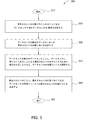
図2は、VMについてのユーザ要求に応答して、クラウド環境のデータセンタ内でVMをプロビジョニングするための方法の一実施形態を示す。方法200のステップは、順番に実施されるものとして示され、説明されているが、ステップは、同時に、および/または提示されているものとは異なる順序で実施されてもよいことに留意されたい。
FIG. 2 illustrates one embodiment of a method for provisioning a VM in a data center in a cloud environment in response to a user request for the VM. It should be noted that although the steps of
ステップ210で、方法200が開始される。方法200は、任意の好適な条件またはトリガに応答して、開始されてよい。
At
ステップ220で、クラウド環境内でのVMのプロビジョニングを要求する、ユーザVM要求が受信される。ユーザVM要求は、ユーザVM要求情報を含む。ユーザVM要求情報は、ユーザによって要求された、いくつかのVMを含む。ユーザVM要求情報はまた、要求されたVMの中で通信するための通信要件を含むことができる。ユーザVM要求情報はまた、1つまたは複数のVM割り当て制約(たとえば、VM配置制約、VM通信制約、VM復元力制約などのうちの1つまたは複数)を含むことができる。ユーザVM要求情報は、データセンタ内で要求されたVMの配置を決定する際の使用に好適な任意の他の情報を含むことができる。
At
ステップ230で、データセンタ内での要求されたVMの割り当てが決定される。データセンタ内での要求されたVMの割り当ては、ユーザVM要求情報、ネットワーク管理情報、データセンタ管理情報など、ならびにそれらのさまざまな組合せを使用して決定される。データセンタ内での要求されたVMの割り当ては、VM割り当て情報の観点から指定されてよい。VM割り当て情報は、要求されたVMが配置されることになるデータセンタの識別情報、要求されたVMが配置されることになるデータセンタ内の機器の(たとえば、各VMが配置されることになる、ラック、ブレードサーバ、およびCPU(およびオプションでコア)の観点からの)識別情報などを含む。VM割り当て情報はまた、要求されたVM同士の間に接続性をプロビジョニングする際の使用のために構成されたネットワーク構成情報を含むことができる。一実施形態において、データセンタ内での要求されたVMの割り当ては、図3に関して示され、説明されるように決定される。
At
ステップ240で、VM割り当て情報を使用して、要求されたVMがクラウド環境内でプロビジョニングされる。クラウド環境内での要求されたVMのプロビジョニングは、任意の好適なやり方で(たとえば、要求されたVMが割り当てられることになるデータセンタに送られたプロビジョニングメッセージを使用して)実施されてよい。
At
ステップ250で、方法200が終了する。
At
図3は、クラウド環境のデータセンタ内でVMをプロビジョニングするのに使用される、データセンタ内でのVMの割り当てを決定するための方法の一実施形態を示す。方法300のステップは、順番に実施されるものとして示され、説明されているが、ステップは、同時に、および/または提示されているものとは異なる順序で実施されてもよいことに留意されたい。
FIG. 3 illustrates one embodiment of a method for determining VM allocation in a data center used to provision VMs in a data center in a cloud environment. Note that although the steps of
ステップ310で、方法300が開始される。
At
ステップ320で、要求されたVMのためのデータセンタの集合が決定される。
At
データセンタの集合は、要求されたVMが割り当てられることになる1つまたは複数のデータセンタを含む。データセンタの集合は、クラウド環境の利用可能なデータセンタのうちの1つまたは複数を含む。単一のデータセンタは要求されたVMのすべてをホストするのに十分な容量を有していないことがあること、および、さらには、単一のデータセンタに要求されたVMのすべてをホストするのに十分な容量がある場合であっても、復元力を改善するために、ユーザが複数のデータセンタにわたって要求されたVMを分散させるよう望むことがあることに留意されたい。 The collection of data centers includes one or more data centers to which the requested VM will be assigned. The collection of data centers includes one or more of the available data centers in the cloud environment. A single data center may not have enough capacity to host all of the requested VMs, and even hosts all of the requested VMs in a single data center It should be noted that even if there is sufficient capacity, the user may want to distribute the requested VMs across multiple data centers to improve resiliency.
データセンタの集合は、ユーザVM要求情報を使用して決定されてよい。データセンタの集合は、ネットワーク管理情報、データセンタ管理情報など、ならびにそれらのさまざまな組合せのうちの1つまたは複数を使用して決定されてよい。データセンタの集合は、データセンタの集合を決定する際の使用に好適な任意の他の情報を使用して決定されてよい。 The set of data centers may be determined using user VM request information. The collection of data centers may be determined using one or more of network management information, data center management information, etc., as well as various combinations thereof. The set of data centers may be determined using any other information suitable for use in determining the set of data centers.
一実施形態において、データセンタの集合は、(1)データセンタの集合の中のデータセンタの数を最小限にする、および(2)要求されたVMの配置に関連付けられたデータセンタ間トラフィックを削減する(およびしたがって、消費されるネットワーク帯域幅を最小限にする)ことにつながるやり方で、決定される。 In one embodiment, the set of data centers (1) minimizes the number of data centers in the set of data centers, and (2) traffic between the data centers associated with the requested VM placement. Determined in a manner that leads to reduction (and thus minimizing network bandwidth consumed).
一実施形態において、データセンタの集合は、(1)任意の2つのデータセンタ間の最大距離(たとえば、ホップカウント)を最小限にし、(2)1つまたは複数の制約(たとえば、所望のVMの数の利用可能性、各データセンタに配置されるVMの最小数および/または最大数、など)に従う、利用可能なデータセンタの部分集合を選択することによって決定される。これらの条件を満たすデータセンタの部分集合の選択は、以下で説明される、部分グラフ選択問題(本明細書では、データセンタ選択問題MINDIAMETERとして示される)と見なされてよいことに留意されたい。 In one embodiment, the collection of data centers (1) minimizes the maximum distance (eg, hop count) between any two data centers, and (2) one or more constraints (eg, desired VMs). For example, the minimum number and / or maximum number of VMs located in each data center, etc.). Note that the selection of a subset of data centers that meet these conditions may be considered a subgraph selection problem (denoted herein as the data center selection problem MINDIAMETER), described below.
利用可能なデータセンタの集合が、グラフ(G)として表されるとする。グラフG=(V,E)は、頂点(V)およびエッジ(E)からなる。頂点(V)は、データセンタに対応する。頂点(V)は、頂点(V)に関連付けられた頂点重み(w)を有し、そこで頂点(V)の重み(w)がデータセンタにおける利用可能なVMの数に対応する。グラフは完全グラフであり、ここで、エッジ(E)は、(たとえば、インターネットおよび/または任意の他の関連したパケットネットワークを介して)データセンタを接続する通信パスに対応する。エッジ(E)は、エッジ(E)に関連付けられたエッジ重み、または長さ(l)を有し、そこで2つのデータセンタ間のエッジ(E)の長さ(l)がデータセンタ同士の間の距離(たとえば、ホップ数)に対応する。 Assume that a set of available data centers is represented as a graph (G). The graph G = (V, E) consists of vertices (V) and edges (E). The vertex (V) corresponds to the data center. Vertex (V) has a vertex weight (w) associated with vertex (V), where the weight (w) of vertex (V) corresponds to the number of VMs available in the data center. The graph is a complete graph, where edge (E) corresponds to a communication path connecting data centers (eg, via the Internet and / or any other associated packet network). The edge (E) has an edge weight or length (l) associated with the edge (E), where the length (l) of the edge (E) between the two data centers is between the data centers. Corresponds to the distance (eg, the number of hops).
一実施形態において、初期のグラフGは、ユーザVM要求において指定されてよい1つまたは複数のVM割り当て制約に基づいて、修正されてよい。ユーザVM要求が、データセンタ内に配置され得るVMの最大数についての制約を含む場合、頂点(V)の重みは、その制約を超えることはできない(すなわち、制約よりも大きい重みを有する頂点は、グラフから取り除かれる)。ユーザVM要求が、データセンタ内に配置され得るVMの最小数についての制約を含む場合、頂点(V)の重みは、その制約に満たないことはできない(すなわち、制約よりも小さい重みを有する頂点は、グラフから取り除かれる)。 In one embodiment, the initial graph G may be modified based on one or more VM allocation constraints that may be specified in the user VM request. If the user VM request includes a constraint on the maximum number of VMs that can be placed in the data center, the vertex (V) weight cannot exceed that constraint (ie, vertices with a weight greater than the constraint are not , Removed from the graph). If the user VM request includes a constraint on the minimum number of VMs that can be placed in the data center, the vertex (V) weight cannot be less than that constraint (ie, a vertex with a weight less than the constraint) Is removed from the graph).
sが、ユーザVM要求において要求されたVMの数を表すとする。一実施形態において、データセンタ選択問題MINDIAMETERは、その重みの総和が少なくともsであって、最小直径を有する、Gの部分グラフ(すなわち、頂点間の任意の最短距離の最大長)を発見することに対応する。オリジナルグラフGは完全グラフなので、選択された頂点によって誘導された部分グラフもまた、完全であることに留意されたい。したがって、一実施形態において、データセンタ選択問題MINDIAMETERは、最も長いエッジの長さが最小である、そのような部分グラフを発見することに対応する。 Let s denote the number of VMs requested in the user VM request. In one embodiment, the data center selection problem MINDIAMETER finds a subgraph of G (ie, the maximum length of any shortest distance between vertices) whose sum of weights is at least s and has a minimum diameter. Corresponding to Note that since the original graph G is a complete graph, the subgraph derived by the selected vertices is also complete. Thus, in one embodiment, the data center selection problem MINDIAMETER corresponds to finding such a subgraph with the longest edge length being the smallest.
データセンタ選択問題MINDIAMETERは、NP困難であり、任意のε>0の場合、2−ε範囲内で近似値を求めることはできないことに留意されたい。データセンタ選択問題MINDIAMETERは、問題が最大サイズのクリークを発見することである、最大クリーク問題からは還元され得ないことにさらに留意されたい。還元は、以下の通りである。最大クリーク問題のインスタンスG=(V,E)が与えられるとすると、最小直径部分グラフ問題のインスタンスが作成される。新しい完全グラフG’=(V’,E’,w,l)が作成される。G’の頂点は、Gの頂点と同じであり、1(1)の重みを有する。Gにおいて、2つの頂点uとvとの間にエッジがある場合、G’の対応する頂点間のエッジの長さは1(1)である。そうでない場合、頂点間のエッジの長さは2(2)である。このグラフにおけるエッジは、三角不等式を満たす。Gにおける対応する部分グラフがクリークのとき、かつそのときに限り、G’の部分グラフは、1(1)の直径を有する。これは、Gがサイズkのクリークを有する場合、G’の対応する頂点は、重みkおよび直径1(1)の部分グラフを形成するように取られてよいからである。同様に、G’が重みkおよび直径1の部分グラフを有する場合、Gの対応する頂点は、サイズkのクリークを形成する。Gにおける対応する部分グラフがクリークのとき、かつそのときに限り、G’の部分グラフは、1(1)の直径を有する。したがって、最大クリーク問題に対する解は、サイズsおよび直径1(1)の部分グラフが存在する最大値s∈{n,n−1,…1}を発見することによって見出されてよい。
Note that the data center selection problem MINDIAMETER is NP-hard, and for any ε> 0, no approximation can be found within the 2-ε range. It is further noted that the data center selection problem MINDIAMETER cannot be reduced from the maximum clique problem, where the problem is to find the maximum size clique. The reduction is as follows. Given an instance of the maximum clique problem G = (V, E), an instance of the minimum diameter subgraph problem is created. A new complete graph G '= (V', E ', w, l) is created. The vertex of G 'is the same as the vertex of G and has a weight of 1 (1). In G, if there is an edge between two vertices u and v, the length of the edge between the corresponding vertices of G ′ is 1 (1). Otherwise, the edge length between vertices is 2 (2). The edges in this graph satisfy the triangle inequality. The subgraph of G 'has a diameter of 1 (1) when and only if the corresponding subgraph in G is a clique. This is because if G has a clique of size k, the corresponding vertex of G 'may be taken to form a subgraph with weight k and diameter 1 (1). Similarly, if G 'has a subgraph with weight k and
データセンタ選択問題MINDIAMETERは、P=NPでない限り、任意のε>0の場合、因子2−ε範囲内で近似値を求めることはできないことに再び留意されたい。データセンタ選択問題MINDIAMETERのための2−ε近似処理が存在する場合、最大クリーク問題は、以下のように解決されてよい。サイズkのクリークを発見するために、上の還元を使用して、重みkを有するMINDIAMETER問題を作成する。サイズkのクリークがある場合、直径1(1)のデータセンタ選択問題MINDIAMETERのための部分グラフが存在する。そのようなクリークがない場合、データセンタ選択問題MINDIAMETERの直径は、少なくとも2(2)である。したがって、データセンタ選択問題MINDIAMETERのための2−ε処理が、その直径が2(2)未満である部分グラフを返すと、オリジナルグラフGに、サイズkのクリークがある。 Note again that the data center selection problem MINDIAMETER cannot find an approximation within the factor 2-ε range for any ε> 0 unless P = NP. If there is a 2-ε approximation for the data center selection problem MINDIAMETER, the maximum clique problem may be solved as follows. To find a clique of size k, the above reduction is used to create a MINIAMETER problem with weight k. If there is a clique of size k, there is a subgraph for the data center selection problem MINDIAMETER of diameter 1 (1). In the absence of such a clique, the diameter of the data center selection problem MINDIAMETER is at least 2 (2). Thus, if the 2-ε process for the data center selection problem MINDIAMETER returns a subgraph whose diameter is less than 2 (2), the original graph G has a clique of size k.
一実施形態において、近似処理が、最小直径部分グラフ問題(すなわち、データセンタ選択問題MINDIAMETER)を解決するために提供される。一実施形態において、処理によって出力される部分グラフの直径は、最適な部分グラフの直径の多くとも2倍である。近似処理では、三角不等式が、グラフにおけるエッジ重みについて成り立つと想定されている。エッジの長さは、対応するデータセンタ同士の間のパス長に対応するので、この問題設定において三角不等式が有効であることに留意されたい。3つのデータセンタ間で三角不等式違反がある場合、より短いエッジで形成されるパスを取るのにより長いエッジを強制することによって、三角不等式への適合がなおも維持され得ることにさらに留意されたい。 In one embodiment, an approximation process is provided to solve the minimum diameter subgraph problem (ie, the data center selection problem MINDIAMETER). In one embodiment, the diameter of the subgraph output by the process is at most twice the diameter of the optimal subgraph. In the approximation process, it is assumed that a triangle inequality holds for edge weights in the graph. Note that the edge inequality corresponds to the path length between corresponding data centers, so the triangle inequality is valid in this problem setting. Note further that if there is a triangle inequality violation between the three data centers, conformance to the triangle inequality can still be maintained by forcing a longer edge to take a path formed by a shorter edge. .
一実施形態において、近似処理は、2つの処理として実装される最小直径部分グラフ問題を解決するために提供され、2つの処理は、本明細書では、以下で説明される、FindMinStar(G,v,s)処理(図4Aで示され、説明されている)、およびMinDiameterGraph(G,s)処理(図4Bで示され、説明されている)として示される。これらの処理は、別々の処理として主に示され、説明されているが、説明される機能を提供するために実行され得る、より少ない、またはより多い処理として実装されてもよいことに留意されたい。これらの処理は、処理の特定の実装(たとえば、特定の変数、処理のステップの特定の配列、など)に関して示され、説明されているが、説明される機能を提供するのに好適な任意の他のやり方で実装されてもよいことにさらに留意されたい。 In one embodiment, an approximation process is provided to solve the minimum diameter subgraph problem implemented as two processes, which are described herein as FindMinStar (G, v , S) processing (shown and described in FIG. 4A) and MinDiameterGraph (G, s) processing (shown and described in FIG. 4B). Although these processes are primarily shown and described as separate processes, it is noted that they may be implemented as fewer or more processes that may be performed to provide the functions described. I want. These processes are shown and described with respect to a particular implementation of the process (eg, a particular variable, a particular arrangement of process steps, etc.), but any suitable to provide the functionality described. Note further that it may be implemented in other ways.
本明細書で触れたように、図4AのFindMinStar(G,v,s)処理410、および図4BのMinDiameterGraph(G,s)処理420は、VMが割り当てられることになるデータセンタの集合を決定するために構成されている。
As mentioned herein, the FindMinStar (G, v, s)
図4Aに示されるように、FindMinStar(G,v,s)処理410は、頂点vを含む、重み少なくともsの部分グラフを発見するように構成されている。頂点vを中心としたスター型トポロジは、スター型トポロジの重みが少なくともsになるまで、vまでの長さの昇順に、ノードを加えることによって発見される。最終的な部分グラフは、スター型におけるノードにより誘導されたエッジを加えることによって形成される。FindMinStar(G,v,s)処理410はまた、ノードが加えられたときの直径を維持することによって、結果として生じる部分グラフの直径を(ノードが加えられたとき、部分グラフの直径は、そのノードによって誘導されたエッジの長さが現在の直径よりも大きい場合にのみ変化することができる、という制約に従って)計算する。
As shown in FIG. 4A, the FindMinStar (G, v, s)
図4Bに示されるように、MinDiameterGraph(G,s)処理420は、頂点のそれぞれについてFindMinStar(G,v,s)処理410を呼び出すことによって、重み少なくともsの部分グラフを発見するように構成されている。MinDiameterGraph(G,s)処理420は次いで、最も小さい直径を有する部分グラフを選択する。
As shown in FIG. 4B, the MinDiameterGraph (G, s)
FindMinStar(G,v,s)処理410は、vに付随する任意のエッジの長さが最小である、重み少なくともsの部分グラフを発見する。FindMinStar(G,v,s)処理410は最初に、頂点vを部分グラフに加える。FindMinStar(G,v,s)処理410は次いで、部分グラフにおける頂点の重みの総和がsになるまで、エッジ重みの昇順に、vに隣接した頂点を加える。したがって、FindMinStar(G,v,s)処理410は、vに付随するエッジについて最も小さいエッジ重みを有する部分グラフを発見する。
A FindMinStar (G, v, s)
MinDiameterGraph(G,s)処理420は、その直径が最適値の多くとも2倍である、重み少なくともsの部分グラフを発見する。MinDiameterGraph(G,s)処理420は、Gの頂点のそれぞれについてFindMinStar(G,v,s)処理410を呼び出し、最小直径を有する1つを選択する。v’が、FindMinStar(G,v,s)処理410によって返されたグラフG’の直径が最小であったノードであるとし、l’が、部分グラフG’においてv’に付随する最も長いエッジの長さであるとする。エッジ長さは三角不等式に従い、G’は完全グラフであるので、G’における任意のエッジの長さは多くとも2l’であり、したがって、G’の直径は、多くとも2l’である。
The MinDiameterGraph (G, s)
データセンタ選択問題MINDIAMETERに関して、データセンタ選択問題MINDIAMETERを解決するための近似処理は、2−近似処理であることに留意されたい。Goptが、データセンタ選択問題MINDIAMETERに対する最適解であるとする。l”が、Goptの最も長いエッジであるとする。u”およびv”が、l”の端点であるとする。Goptのエッジは、三角不等式を満たすので、u”とv”との間のGoptにおける最短距離は、l”である。したがって、Goptの直径は、少なくともl”である。次に、MinDiameterGraph(G,s)処理420を実行しながら、FindMinStar(G,v,s)処理410によって返されたグラフG”について検討する。上で触れたように、G”の上でv”に付随するエッジの長さは、多くともl”である。G”の直径は、多くとも2l”であるので、MinDiameterGraph処理420によって返された部分グラフ(すなわち、G’)の直径は、多くとも2l”である。したがって、データセンタ選択問題MINDIAMETERを解決するための近似処理は、2−近似処理である。
Regarding the data center selection problem MINDIAMETER, it should be noted that the approximation process for solving the data center selection problem MINDIAMETER is a 2-approximation process. Let G opt be the optimal solution to the data center selection problem MINDIAMETER. Let l ″ be the longest edge of G opt. Let u ″ and v ″ be the endpoints of l ″. Since the edge of G opt satisfies the triangular inequality, the shortest distance in G opt between u ″ and v ″ is l ″. Therefore, the diameter of G opt is at least l ″. Next, consider the graph G ″ returned by the FindMinStar (G, v, s)
次に図3に戻ると、要求されたVMのためのデータセンタの集合の決定が、他のやり方で(たとえば、他の情報を使用して、他の条件を満たすためのやり方で、他の処理を使用してなど、ならびにそれらのさまざまな組合せで)実施されてもよいことに留意されたい。 Returning now to FIG. 3, the determination of the set of data centers for the requested VM may be performed in other ways (eg, using other information to meet other conditions, Note that it may be performed using processes, etc., as well as various combinations thereof.
ステップ330で、データセンタの集合の中のデータセンタへの要求されたVMの割り当てが決定される。
At
データセンタの集合の中のデータセンタへの要求されたVMの割り当ては、データセンタの集合のデータセンタごとに、データセンタに割り当てられることになる要求されたVMの数を指定する。データセンタの集合の中のデータセンタへの要求されたVMの割り当ては、必ずしも、VMが割り当てられることになるデータセンタの機器(これはステップ340で決定されてよいので)、またはVMのうちのどれがデータセンタのうちのどれに割り当てられることになるか(これはステップ350で決定されてよいので)を、指定するものではないことに留意されたい。 The allocation of requested VMs to data centers in a set of data centers specifies, for each data center in the set of data centers, the number of requested VMs that will be allocated to the data center. The allocation of a requested VM to a data center in the set of data centers is not necessarily the data center equipment (as this may be determined in step 340) to which the VM will be allocated, or Note that it does not specify which of the data centers will be assigned (since this may be determined in step 350).
要求されたVMは、ユーザVM要求情報、ネットワーク管理情報、データセンタ管理情報など、ならびにそれらのさまざまな組合せのうちの1つまたは複数を使用して、データセンタの集合の中のデータセンタに割り当てられてよい。一実施形態において、要求されたVMは、データセンタ間トラフィックを最小限にすることにつながるやり方で、データセンタの集合の中のデータセンタに割り当てられる。一実施形態において、要求されたVMは、ユーザVM要求において指定された1つまたは複数のVM割り当て制約に従って、データセンタの集合の中のデータセンタに割り当てられる。たとえば、複数の異なるタイプのVMを複数の異なるデータセンタに割り当てることに関連付けられたVMタイプ制約を、ユーザVM要求情報が含む一実施形態では、要求されたVMが、VMタイプ制約に基づいて、データセンタの集合の中のデータセンタに割り当てられる。 The requested VM is assigned to a data center in a set of data centers using one or more of user VM request information, network management information, data center management information, etc., and various combinations thereof. May be. In one embodiment, the requested VM is assigned to a data center in a collection of data centers in a manner that leads to minimizing inter-data center traffic. In one embodiment, the requested VM is assigned to a data center in the set of data centers according to one or more VM assignment constraints specified in the user VM request. For example, in one embodiment where the user VM request information includes VM type constraints associated with assigning a plurality of different types of VMs to a plurality of different data centers, the requested VM is based on the VM type constraints, Assigned to a data center in a set of data centers.
一実施形態において、要求されたVMは、VMをデータセンタに割り当てるために構成されたVM割り当て処理を使用して、データセンタの集合の中のデータセンタに割り当てられる。概して、VM割り当て処理の目的は、グラフの断片同士の間にいくつかの関係が存在するように、グラフを均等なサイズの断片に分ける(それにより、要求されたVMをサポートするのに必要とされるネットワーク通信リソースを最小限にする)ことである。しかしながら、一般にグラフ二分割問題と呼ばれる、グラフを2つの均等な断片に分ける最も単純なケースでさえ、NP困難である。加えて、関連した問題は、その目的がグラフをK個の断片に分けることであるK−カット問題であり、ここで、各断片のサイズはやはり、入力として指定される。 In one embodiment, the requested VM is assigned to a data center in a set of data centers using a VM assignment process configured to assign the VM to the data center. In general, the purpose of the VM allocation process is to divide the graph into equally sized pieces so that there are some relationships between the pieces of the graph (thus required to support the requested VM). Network communication resources to be minimized). However, even the simplest case of dividing a graph into two equal pieces, commonly called the graph bisection problem, is NP-hard. In addition, a related problem is the K-cut problem whose purpose is to divide the graph into K pieces, where the size of each piece is again specified as an input.
VM割り当て処理において、ユーザVM要求は、分割されることが必要なグラフとして見なされてよい。グラフのノードは、VMを表し、グラフのリンクは、リンクによって接続された対のVMの間で必要とされる相対帯域幅を表す。グラフの各パーティションは、同じデータセンタに割り当てられることが必要なVMの集合を表す。各パーティションのサイズは、VMをホストするためにデータセンタにおいて利用可能なリソースの量によって上に有界である必要がある。従来のグラフ分割問題とは異なり、この問題は、各パーティションにおける厳密なノードの数を指定しなくてもよく、代わりに、各パーティションにおける最大ノードのみを指定する。これは、任意の点において、クラウド環境においてVMをホストするために利用可能なリソースが、ユーザによって要求されたVMの数よりも多い場合があるからである。その結果、VM割り当て処理は、VMをホストするために利用可能な最大リソースを有するデータセンタ内でVMを割り当てることによって、(データセンタ同士の間の)通信を最適化することができる。データセンタへのVMの割り当てでは、データセンタ間通信コストは、データセンタ同士の間の通信ルーティングに依存する。したがって、適用する通信コストを最小限にするために、データセンタパーティション同士の間の通信距離が考慮に入れられる。 In the VM allocation process, user VM requests may be viewed as a graph that needs to be split. The graph nodes represent VMs and the graph links represent the relative bandwidth required between the paired VMs connected by the links. Each partition of the graph represents a set of VMs that need to be assigned to the same data center. The size of each partition needs to be bounded above by the amount of resources available in the data center to host the VM. Unlike the traditional graph partitioning problem, this problem does not require specifying the exact number of nodes in each partition, but instead specifies only the largest node in each partition. This is because at any point, there may be more resources available to host a VM in the cloud environment than the number of VMs requested by the user. As a result, the VM allocation process can optimize communication (between data centers) by allocating VMs within the data center that has the maximum resources available to host the VM. In the allocation of VMs to data centers, the communication cost between data centers depends on the communication routing between the data centers. Therefore, the communication distance between data center partitions is taken into account in order to minimize the applied communication cost.
VM割り当て処理に関して、問題は以下のように導き出されてよい。エッジ重みwが割り当てられたグラフG=(V,E):E→N、およびパーティションiとjとの間の距離をd(i,j)としてパーティション容量k1,k2,・・・の集合が与えられるとする。Vを、|Ci|≦Kiおよび With respect to the VM allocation process, the problem may be derived as follows. Graph G = (V, E) to which edge weight w is assigned: E → N, and a set of partition capacities k1, k2,..., Where d (i, j) is a distance between partitions i and j. Suppose you are given. V is | C i | ≦ K i and
![]()
![]()
VM割り当て処理に関して、個々のユーザ要求がインクリメント方式で別々に扱われてもよく、または、すべての複数の要求がまとめて結合されて、異なるユーザ要求のノード同士の間にいかなるエッジも含まない大きく分割されたグラフを形成してもよいことに留意されたい。 With respect to the VM allocation process, individual user requests may be handled separately in increments, or all multiple requests may be combined together to include no edges between nodes of different user requests. Note that a segmented graph may be formed.
VM割り当て処理に関して、グラフ分割問題はNP困難であり、良好な(たとえば、一定の)近似保証を有する処理は存在しないことに留意されたい。 Note that for the VM allocation process, the graph partitioning problem is NP-hard, and no process has a good (eg, constant) approximation guarantee.
一実施形態において、VM割り当て処理は、貪欲法に基づく発見的処理として実装される。 In one embodiment, the VM allocation process is implemented as a heuristic process based on greedy methods.
一実施形態において、VM割り当て処理は、一度に1つのデータセンタを選択する。データセンタは、任意の好適な順序で選択されてよく(たとえば、各選択は、ユーザVM要求において指定された1つまたは複数のVM割り当て制約など、ならびにそのさまざまな組合せに基づいて、VMをホストするために利用可能なリソースの最大量を有するデータセンタが選択されるように、実施される)、選択されたデータセンタに、可能な限り多くのVMを割り当てる。VM割り当て処理は、パラメータの最大値(たとえば、着信/発信帯域幅、近傍の数、など)を有するVMを選択し、選択されたVMを、選択されたデータセンタに割り当てる。選択されたVMは、選択されたデータセンタに割り当てられるVMの集合である集合Cに加えられる。VM割り当て処理は次いで、Cの近傍のすべてを考慮し、Cへの/Cからの最大トラフィックを有するVMを選択し、選択されたVMを集合Cに加える。この処理は、選択されたデータセンタについて条件が満たされる(たとえば、選択されたデータセンタの利用可能なリソースのすべてが使い尽くされる、選択されたデータセンタについてデータセンタごとのVMの最大量の制約が満たされる、など)まで、繰り返されてよい。VM割り当て処理は次いで、次のデータセンタを選択し、次の選択されたデータセンタ、およびデータセンタにまだ割り当てられていない残りのVM(すなわち、V−C)のグラフについて、処理を繰り返す。 In one embodiment, the VM allocation process selects one data center at a time. The data centers may be selected in any suitable order (eg, each selection hosts VMs based on one or more VM allocation constraints specified in the user VM request, etc., as well as various combinations thereof) (Implemented so that the data center with the maximum amount of resources available to do is selected), assign as many VMs as possible to the selected data center. The VM allocation process selects a VM having a maximum value of parameters (eg, incoming / outgoing bandwidth, number of neighbors, etc.) and allocates the selected VM to the selected data center. The selected VM is added to set C, which is a set of VMs assigned to the selected data center. The VM allocation process then considers all of C's neighbors, selects the VM with the most traffic to / from C, and adds the selected VM to set C. This process is constrained for the selected data center (for example, a constraint on the maximum amount of VMs per data center for the selected data center where all available resources of the selected data center are exhausted). Until it is satisfied, etc.). The VM assignment process then selects the next data center and repeats the process for the next selected data center and the remaining VM (ie, VC) graphs that have not yet been assigned to the data center.
一実施形態において、VM割り当て処理は、特定のノードを交換することによって修正される。VM割り当て処理は、複数の異なるパーティションに存在する対のノードを考慮する。VM処理は、考慮されたノードの入れ替えが解を改善するか否か(たとえば、より少ないデータセンタ間帯域幅を使用するか)を判定することができる。VM処理は、パーティション同士の間でノードを(たとえば、ノードの現在のパーティションから利用可能な容量を有する複数の異なるパーティションへ)移動させることが、解を改善するか否かを判定することができる。VM割り当て処理は、考慮された移動のうちの1つまたは複数を選択し、選択された移動をコミットする。この処理は、繰り返されてよい(たとえば、閾値の移動の数がコミットされるまで、すべての移動が考慮されてVM割り当てにおいてそれ以上の改善がなくなるまで、など)ことに留意されたい。 In one embodiment, the VM allocation process is modified by exchanging specific nodes. The VM allocation process considers pairs of nodes that exist in multiple different partitions. The VM processing can determine whether the considered node replacement improves the solution (eg, uses less inter-data center bandwidth). VM processing can determine whether moving a node between partitions (eg, from the current partition of the node to a number of different partitions with available capacity) improves the solution. . The VM allocation process selects one or more of the considered movements and commits the selected movement. Note that this process may be repeated (eg, until all thresholds are considered and there is no further improvement in VM allocation until the threshold number of moves is committed, etc.).
ステップ340で、データセンタの集合の中のデータセンタごとに、データセンタに割り当てられることになる要求されたVMをホストするために使用されることになる、データセンタの物理リソースが選択される。
At
データセンタ内の物理リソースの選択は、データセンタに割り当てられるVMをホストするために使用されることになるデータセンタのラックの選択を含むことができる。データセンタ内の物理リソースの選択は、選択されたラック上のブレードサーバの選択をさらに含むことができる。データセンタ内の物理リソースの選択は、選択されたラックの選択されたブレードサーバ上のCPUの選択をさらに含むことができる。データセンタ内の物理リソースの選択は、選択されたラックの選択されたブレードサーバの選択されたCPUのコアの選択をさらに含むことができる。この意味において、データセンタ内の物理リソースの選択に使用される処理は、本明細書ではより広く、機器選択処理、マシン選択処理、および/または物理リソース選択処理と呼ばれてもよい。物理リソースの選択は、必ずしも、データセンタに割り当てられることになるVMの、データセンタの選択された物理リソースへのマッピング(これはステップ350で決定されてよいので)を指定するものではないことに留意されたい。 The selection of physical resources within the data center can include the selection of the rack of the data center that will be used to host the VMs assigned to the data center. The selection of physical resources in the data center can further include selection of blade servers on the selected rack. The selection of physical resources in the data center can further include selection of CPUs on selected blade servers in the selected rack. The selection of the physical resource in the data center may further include selection of the core of the selected CPU of the selected blade server of the selected rack. In this sense, the process used to select a physical resource in a data center is broader in this specification and may be referred to as a device selection process, a machine selection process, and / or a physical resource selection process. The selection of the physical resource does not necessarily specify the mapping of the VM that will be allocated to the data center to the selected physical resource of the data center (as this may be determined in step 350). Please keep in mind.
データセンタの物理リソースの選択は、データセンタ内のVM同士の間のラック間トラフィックを最小限にすることにつながるやり方で実施されてよい。これは、データセンタに割り当てられるVM同士の間の長い通信パスを防ぐことにつながることになり、それにより、データセンタ内のVM同士の間の通信における大きな待ち時間を防いで、データセンタ内のリソース(たとえば、通信リソース)の使用量を削減する。 The selection of data center physical resources may be performed in a manner that leads to minimizing inter-rack traffic between VMs in the data center. This leads to prevention of long communication paths between VMs allocated to the data center, thereby preventing a large waiting time in communication between VMs in the data center, and in the data center. Reduce the usage of resources (eg, communication resources).
これにより、互いに比較的近接して設置されていないラック同士の間の任意の通信が、さまざまな数/レベルのアグリゲーションスイッチを横断しなければならないことがある、より大規模なデータセンタ(たとえば、数百のラック、数千のラック、またはそれ以上ものラックを有するデータセンタ)において、通信遅延の著しい削減を実現することができる。 This allows any communication between racks that are not installed relatively close to each other to have a larger data center (e.g., for example) that may have to traverse various numbers / levels of aggregation switches. In data centers having hundreds of racks, thousands of racks, or more, significant reductions in communication delay can be realized.
データセンタの物理リソースの選択は、順応性を提供することにつながるやり方で実施されてよい。 The selection of physical resources in the data center may be performed in a manner that leads to providing flexibility.
データセンタの物理リソースの選択は、データセンタの利用、およびVMが要求されるユーザアプリケーションのパフォーマンスを改善できることに留意されたい。 It should be noted that the selection of data center physical resources can improve data center utilization and user application performance where VMs are required.
一実施形態において、選択されたデータセンタのラックの選択は、ラック選択処理(たとえば、要求されたVMのためのラックが選択されるマシン選択処理の実装)を使用して実施される。 In one embodiment, selection of a selected data center rack is performed using a rack selection process (eg, an implementation of a machine selection process in which a rack for a requested VM is selected).
一実施形態において、ラック選択処理は、データセンタの選択のために使用されるデータセンタ選択処理の修正版として実装される。この実施形態において、ラック選択処理は、ラック同士の間の最大距離を最小限にするように構成された2−近似処理である。この実施形態において、グラフの頂点がラックを表し、ラックごとに、ラックの関連付けられた重みが、データセンタに割り当てられたVMをサポートするためのラックにおいて利用可能なリソースの量を表す。 In one embodiment, the rack selection process is implemented as a modified version of the data center selection process used for data center selection. In this embodiment, the rack selection process is a 2-approximation process configured to minimize the maximum distance between racks. In this embodiment, the vertices of the graph represent racks, and for each rack, the associated weight of the rack represents the amount of resources available in the rack to support the VM assigned to the data center.
データセンタのトポロジが階層構造ネットワークである一実施形態において、ラック選択処理は、ラック選択問題に対する最適な解を決定することができる。トポロジは、ツリー型トポロジと考えられてよく、ここでは、ツリーの根ノードが、最も高い層の1つまたは複数のスイッチ(たとえば、データセンタへの/データセンタからの接続性を提供するルータ)を表し、根ノードの子ノードが、スイッチのネットワーク層(たとえば、上位レベルのアグリゲートスイッチ)を表すなどして、ラックを表す葉ノードまで下りてくる。このツリーでは、葉ノードのすべてが同じレベルにあることに留意されたい。ツリーは、データセンタに割り当てられたVMをサポートするための利用可能なラックのリソースの量をラックごとに示すラベルを含んで、拡大する。 In one embodiment where the data center topology is a hierarchical network, the rack selection process can determine an optimal solution to the rack selection problem. The topology may be thought of as a tree topology, where the root node of the tree is one or more switches in the highest layer (eg, a router that provides connectivity to / from the data center). The child node of the root node descends to the leaf node representing the rack, for example, representing the network layer of the switch (for example, a higher level aggregate switch). Note that in this tree, all of the leaf nodes are at the same level. The tree expands with a label indicating the amount of available rack resources for each rack to support the VMs assigned to the data center.
一実施形態において、ラックのブレードサーバの選択は、ブレードサーバ選択処理(たとえば、要求されたVMのためのラックおよびブレードサーバが選択される、マシン選択処理の実装)を使用して実施される。一実施形態において、ブレードサーバ選択処理は、ラック選択処理の修正版として実装され、ここでは、ツリーの葉ノードがブレードサーバのレベルを表し、葉ノードの親ノードがラックを表す。 In one embodiment, the selection of a blade server for a rack is performed using a blade server selection process (eg, an implementation of a machine selection process where a rack and blade server for a requested VM is selected). In one embodiment, the blade server selection process is implemented as a modified version of the rack selection process, where the leaf node of the tree represents the blade server level and the parent node of the leaf node represents the rack.
一実施形態において、ラックのブレードサーバのCPUの選択は、CPU選択処理(たとえば、要求されたVMのためのラック、ブレードサーバ、およびCPUが選択される、マシン選択処理の実装を使用する)を使用して実施される。一実施形態において、CPU選択処理は、ラック選択処理の修正版として実装され、ここでは、ツリーの葉ノードがCPUのレベルを表し、CPUノードの親ノードがブレードサーバを表し、ブレードサーバノードの親ノードがラックを表す。 In one embodiment, the selection of a rack blade server CPU uses a CPU selection process (eg, using a machine selection process implementation in which the rack, blade server, and CPU for the requested VM are selected). Implemented using. In one embodiment, the CPU selection process is implemented as a modified version of the rack selection process, where the leaf node of the tree represents the CPU level, the parent node of the CPU node represents the blade server, and the parent of the blade server node. A node represents a rack.
上で説明されたように、マシン選択処理は、データセンタに割り当てられるVMが割り当てられることになる、データセンタ内でのマシンを選択するための、データセンタについて実行されてよい。 As described above, the machine selection process may be performed for a data center to select a machine in the data center to which a VM assigned to the data center will be assigned.
一実施形態において、マシン選択処理は、VMが割り当てられた所与のデータセンタについて、データセンタに割り当てられた任意の2つのVMの間の最大通信距離を最小限にするように構成されている。これは、葉のラベルの総和が少なくとも要求されたVMのターゲット数である、最小高さの根付き部分ツリーを発見することに変換されてよい。データセンタ選択処理でのように、マシン選択処理は、1つまたは複数のVM割り当て制約(たとえば、ラックごとに割り当てられ得るVMの最大数、ラックごとに割り当てられ得るVMの最小数、など)を考慮に入れることができる。これらのタイプのVM割り当て制約は、VM割り当て制約に従ってラックを表すノードの重みを変化させることによって説明されてよい。 In one embodiment, the machine selection process is configured to minimize the maximum communication distance between any two VMs assigned to a data center for a given data center assigned a VM. . This may be translated into finding a minimum-height rooted subtree where the sum of the leaf labels is at least the requested number of target VMs. As in the data center selection process, the machine selection process can include one or more VM allocation constraints (eg, the maximum number of VMs that can be allocated per rack, the minimum number of VMs that can be allocated per rack, etc.). Can be taken into account. These types of VM allocation constraints may be described by changing the weight of the node representing the rack according to the VM allocation constraints.
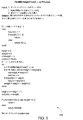
一実施形態において、(図5で示され、説明されている)マシン選択処理は、FindMinHeightTree(T,r,s)処理として実装される。 In one embodiment, the machine selection process (shown and described in FIG. 5) is implemented as a FindMinHeightTree (T, r, s) process.
図5に示されるように、FindMinHeightTree(T,r,s)処理500は、所与のデータセンタについて、そのデータセンタに割り当てられたVMをホストするために使用されることになる、データセンタの物理リソースを選択するように構成されている。sが、データセンタ内で割り当てられることになるVMの数であるとする。Tが、データセンタリソース(たとえば、コンピューティングリソース、ネットワークリソース、など)のツリー表現であるとする。以下の2つの変数が、Tにおける各ノードに関連付けられる:(1)ノードvに根付いた、VMをサポートするための利用可能なデータセンタリソースの量を表す重み(v)、および(2)ノードの高さを表す高さ(v)。葉ノードのみの重み変数が、初期化される。FindMinHeightTree(T,r,s)処理500は、その葉ノードが、少なくともsの累積重み、およびその最小高さを有する、rに根付いた部分ツリーを発見する。FindMinHeightTree(T,r,s)処理500は、ツリーの間順走査を実施し、各ノードの高さおよび重み、ならびに重み少なくともsを有する最小高さ部分ツリーの根を維持する。
As shown in FIG. 5, a FindMinHeightTree (T, r, s)
次に図3に戻ると、データセンタの物理リソースの選択が、他のやり方で(たとえば、他の情報を使用して、他の条件を満たすためのやり方で、他の処理を使用してなど、ならびにそれらのさまざまな組合せで)実施されてもよいことに留意されたい。 Returning now to FIG. 3, data center physical resource selection may be performed in other ways (eg, using other information, in a manner to meet other conditions, using other processing, etc. Note that it may be implemented as well as various combinations thereof.
ステップ350で、要求されたVMごとに、要求されたVMが割り当てられたデータセンタの物理リソースへの、要求されたVMの割り当てが決定される。
At
データセンタの物理リソースへのVMの割り当ては、VMがホストされることになるラック、ブレードサーバ、ならびにCPU(およびオプションで、CPUのコア)へのVMの割り当てを含む。 The allocation of VMs to data center physical resources includes the allocation of VMs to racks, blade servers, and CPUs (and optionally, cores of CPUs) where VMs will be hosted.
要求されたVMは、ユーザVM要求情報、データセンタ管理情報など、ならびにそれらのさまざまな組合せのうちの1つまたは複数を使用して、VMがホストされることになるデータセンタの物理リソースに割り当てられてよい。一実施形態において、VMがホストされることになるデータセンタの物理リソースへのVMの割り当ては、データセンタ内でのラック間トラフィックを最小限にすることにつながるやり方で実施されてよい。一実施形態において、VMがホストされることになるデータセンタの物理リソースへのVMの割り当ては、要求されたVMは、ユーザVM要求において指定された1つまたは複数のVM割り当て制約に従って、実施されてよい。たとえば、複数の異なるタイプのVMを複数の異なるデータセンタに割り当てることに関連付けられたVMタイプ制約を、ユーザVM要求情報が含む一実施形態では、VMがホストされることになるデータセンタの物理リソースへのVMの割り当てが、VMタイプ制約に基づいて、実施されてよい。 The requested VM is allocated to the physical resources of the data center where the VM will be hosted using one or more of user VM request information, data center management information, etc., as well as various combinations thereof. May be. In one embodiment, the allocation of VMs to the physical resources of the data center where VMs will be hosted may be implemented in a manner that leads to minimizing inter-rack traffic within the data center. In one embodiment, the allocation of the VM to the physical resource of the data center where the VM will be hosted is performed according to the one or more VM allocation constraints specified in the user VM request. It's okay. For example, in one embodiment where user VM request information includes VM type constraints associated with assigning a plurality of different types of VMs to a plurality of different data centers, the physical resources of the data center where the VM will be hosted The assignment of VMs to may be performed based on VM type constraints.
一実施形態において、VMがホストされることになるデータセンタの物理リソースへのVMの割り当ては、VMをデータセンタの物理リソースに割り当てるために構成されたVM割り当て処理を使用して実施される。概して、VM割り当て処理の目的は、グラフの断片同士の間にいくつかの関係が存在するように、グラフを均等なサイズの断片に分ける(それにより、データセンタ内でホストされることになる要求されたVMをサポートするのに必要とされるデータセンタ通信リソースを最小限にする)ことである。しかしながら、一般にグラフ二分割問題と呼ばれる、グラフを2つの均等な断片に分ける最も単純なケースでさえ、NP困難である。加えて、関連した問題は、その目的がグラフをK個の断片に分けることであるK−カット問題であり、ここで、各断片のサイズはやはり、入力として指定される。 In one embodiment, the allocation of VMs to data center physical resources where the VMs will be hosted is performed using a VM allocation process configured to allocate VMs to data center physical resources. In general, the purpose of the VM allocation process is to divide the graph into equally sized pieces so that there are some relationships between the pieces of the graph (so that requests that will be hosted in the data center). Minimizing data center communication resources needed to support a designated VM). However, even the simplest case of dividing a graph into two equal pieces, commonly called the graph bisection problem, is NP-hard. In addition, a related problem is the K-cut problem whose purpose is to divide the graph into K pieces, where the size of each piece is again specified as an input.
VM割り当て処理において、ユーザVM要求は、分割されることが必要なグラフとして見なされてよい。グラフのノードは、VMを表し、グラフのリンクは、リンクによって接続された対のVMの間で必要とされる相対帯域幅を表す。グラフの各パーティションは、同じラックに割り当てられることが必要なVMの集合を表す。各パーティションのサイズは、VMをホストするためのラックにおいて利用可能なリソースの量によって上に有界である必要がある。従来のグラフ分割問題とは異なり、この問題は、各パーティションにおける厳密なノードの数を指定しなくてもよく、代わりに、各パーティションにおける最大ノードのみを指定する。これは、任意の点において、クラウド環境においてVMをホストするために利用可能なリソースが、ユーザによって要求されたVMの数よりも多い場合があるからである。その結果、VM割り当て処理は、VMをホストするために利用可能な最大リソースを有するラック内でVMを割り当てることによって、(ラック同士の間の)通信を最適化することができる。データセンタ内でのVMの割り当てでは、ラック同士の間のデータセンタ内通信コストは、データセンタの階層の切り替えにおけるラックの近さに依存してよい。したがって、適用する通信コストを最小限にするために、ラックパーティション同士の間の通信距離が考慮に入れられる。 In the VM allocation process, user VM requests may be viewed as a graph that needs to be split. The graph nodes represent VMs and the graph links represent the relative bandwidth required between the paired VMs connected by the links. Each partition of the graph represents a set of VMs that need to be assigned to the same rack. The size of each partition needs to be bounded above by the amount of resources available in the rack for hosting the VM. Unlike the traditional graph partitioning problem, this problem does not require specifying the exact number of nodes in each partition, but instead specifies only the largest node in each partition. This is because at any point, there may be more resources available to host a VM in the cloud environment than the number of VMs requested by the user. As a result, the VM allocation process can optimize communication (between racks) by allocating VMs within a rack that has the maximum resources available to host the VM. In the allocation of VMs within a data center, the intra-data center communication cost between racks may depend on the proximity of the racks when switching the hierarchy of data centers. Therefore, the communication distance between rack partitions is taken into account in order to minimize the applied communication cost.
VM割り当て処理に関して、問題は以下のように導き出されてよい。エッジ重みw:E→Nが割り当てられたグラフG=(V,E)、およびパーティションiとjとの間の距離をd(i,j)としてパーティション容量k1,k2,・・・の集合が与えられるとする。Vを、|Ci|≦Kiおよび With respect to the VM allocation process, the problem may be derived as follows. A graph G = (V, E) to which edge weight w: E → N is assigned, and a set of partition capacities k1, k2,..., Where d (i, j) is a distance between partitions i and j. Suppose you are given. V is | C i | ≦ K i and
![]()
![]()
VM割り当て処理に関して、個々のユーザ要求がインクリメント方式で別々に扱われてもよく、または、すべての複数の要求がまとめて結合されて、複数の異なるユーザ要求のノード同士の間にいかなるエッジも含まない大きく分割されたグラフを形成してもよいことに留意されたい。 With respect to the VM allocation process, individual user requests may be handled separately in an incremental manner, or all multiple requests may be combined together to include any edge between nodes of different user requests. It should be noted that not very divided graphs may be formed.
VM割り当て処理に関して、グラフ分割問題はNP困難であり、良好な(たとえば、一定の)近似保証を有する処理は存在しないことに留意されたい。 Note that for the VM allocation process, the graph partitioning problem is NP-hard, and no process has a good (eg, constant) approximation guarantee.
一実施形態において、VM割り当て処理は、貪欲法に基づく発見的処理として実装される。 In one embodiment, the VM allocation process is implemented as a heuristic process based on greedy methods.
一実施形態において、VM割り当て処理は、一度に1つのラックを選択する。ラックは、任意の好適な順序で選択されてよく(たとえば、各選択は、ユーザVM要求において指定された1つまたは複数のVM割り当て制約など、ならびにそのさまざまな組合せに基づいて、VMをホストするために利用可能なリソースの最大量を有するラックが選択されるように、実施される)、選択されたラックに、可能な限り多くのVMを割り当てる。VM割り当て処理は、パラメータの最大値(たとえば、着信/発信帯域幅、近傍の数、など)を有するVMを選択し、選択されたVMを、選択されたラックに割り当てる。選択されたVMは、選択されたラックに割り当てられるVMの集合である集合Cに加えられる。VM割り当て処理は次いで、Cの近傍のすべてを考慮し、Cへの/Cからの最大トラフィックを有するVMを選択し、選択されたVMを集合Cに加える。この処理は、選択されたラックの利用可能なリソースのすべてが使い尽くされるまで、繰り返される。VM割り当て処理は次いで、(VMをホストするために利用可能なリソースの最大量を有する)次のラックを選択し、次の選択されたラック、およびまだ割り当てられていない残りのVM(すなわち、V−C)のグラフについて、処理を繰り返す。 In one embodiment, the VM allocation process selects one rack at a time. The racks may be selected in any suitable order (eg, each selection hosts a VM based on one or more VM allocation constraints specified in the user VM request, etc., as well as various combinations thereof) (Implemented so that the rack with the maximum amount of resources available for selection is selected), assign as many VMs as possible to the selected rack. The VM allocation process selects a VM having a maximum value of parameters (eg, incoming / outgoing bandwidth, number of neighbors, etc.) and allocates the selected VM to the selected rack. The selected VM is added to set C, which is the set of VMs assigned to the selected rack. The VM allocation process then considers all of C's neighbors, selects the VM with the most traffic to / from C, and adds the selected VM to set C. This process is repeated until all of the available resources of the selected rack are exhausted. The VM allocation process then selects the next rack (with the maximum amount of resources available to host the VM), the next selected rack, and the remaining VMs that have not yet been allocated (ie, V The process is repeated for the graph of -C).
一実施形態において、VM割り当て処理は、特定のノードを交換することによって修正される。VM割り当て処理は、複数の異なるパーティションに存在する対のノードを考慮する。VM処理は、考慮されたノードの入れ替えが解を改善するか否か(たとえば、より少ないラック間帯域幅を使用するか)を判定することができる。VM処理は、パーティション同士の間でノードを(たとえば、ノードの現在のパーティションから利用可能な容量を有する複数の異なるパーティションへ)移動させることが、解を改善するか否かを判定することができる。VM割り当て処理は、考慮された移動のうちの1つまたは複数を選択し、選択された移動をコミットする。この処理は、繰り返されてよい(たとえば、閾値の移動の数がコミットされるまで、すべての移動が考慮されてVM割り当てにおいてそれ以上の改善がなくなるまで、など)ことに留意されたい。 In one embodiment, the VM allocation process is modified by exchanging specific nodes. The VM allocation process considers pairs of nodes that exist in multiple different partitions. The VM processing can determine whether the considered node replacement improves the solution (eg, uses less inter-rack bandwidth). VM processing can determine whether moving a node between partitions (eg, from the current partition of the node to a number of different partitions with available capacity) improves the solution. . The VM allocation process selects one or more of the considered movements and commits the selected movement. Note that this process may be repeated (eg, until all thresholds are considered and there is no further improvement in VM allocation until the threshold number of moves is committed, etc.).
ステップ360で、方法300が終了する。
At
本明細書では、仮想リソースが仮想マシン(VM)であり、物理リソースがブレードサーバのプロセッサである実施形態のコンテキスト内で主に示され、説明されたが、仮想リソース割り当て能力は、さまざまな他のタイプの仮想リソースの割り当てを決定する、および/またはさまざまな他のタイプの物理リソースへの割り当てを決定するために、使用されてもよいことに留意されたい。したがって、本明細書で使用される、VMの割り当てに固有なさまざまな用語は、仮想リソースの割り当てへの言及として、より広く読まれてもよい。たとえば、本明細書でのVMおよびVM割り当てへの言及は、それぞれ仮想リソースおよび仮想リソース割り当てとして、より広く読まれてもよい。たとえば、本明細書でのVM割り当ての間に使用されるVM割り当て制約(たとえば、VM配置制約、VM通信制約、VM復元力制約、VMタイプ制約、など)への言及は、仮想リソース割り当ての間に使用される仮想リソース割り当て制約(たとえば、仮想リソース配置制約、仮想リソース通信制約、仮想リソース復元力制約、仮想リソースタイプ制約、など)として、より広く読まれてもよい。さまざまな他のVM固有の用語もまた、同様のやり方で、より広く読まれてもよいことに留意されたい。 Although this specification has primarily shown and described within the context of an embodiment where the virtual resource is a virtual machine (VM) and the physical resource is a processor of a blade server, the virtual resource allocation capability may vary widely. It should be noted that it may be used to determine the allocation of various types of virtual resources and / or to determine the allocation to various other types of physical resources. Accordingly, as used herein, various terms specific to VM allocation may be read more broadly as a reference to virtual resource allocation. For example, references herein to VMs and VM assignments may be read more broadly as virtual resources and virtual resource assignments, respectively. For example, references to VM allocation constraints (e.g., VM placement constraints, VM communication constraints, VM resiliency constraints, VM type constraints, etc.) used during VM allocation herein are used during virtual resource allocation. May be read more widely as virtual resource allocation constraints (eg, virtual resource placement constraints, virtual resource communication constraints, virtual resource resiliency constraints, virtual resource type constraints, etc.) used in Note that various other VM specific terms may also be read more broadly in a similar manner.
図6は、本明細書で説明される機能を実施する際の使用に好適なコンピュータの高レベルブロック図を示す。 FIG. 6 shows a high level block diagram of a computer suitable for use in performing the functions described herein.
図6に示されるように、コンピュータ600は、プロセッサ要素602(たとえば、中央処理ユニット(CPU)および/または他の好適なプロセッサ)、およびメモリ604(たとえば、ランダムアクセスメモリ(RAM)、読み出し専用メモリ(ROM)、など)を含む。コンピュータ600はまた、協働モジュール/処理605、および/またはさまざまな入力/出力デバイス606(たとえば、ユーザ入力デバイス(キーボード、キーパッド、マウス、その他など)、ユーザ出力デバイス(ディスプレイ、スピーカ、その他など)、入力ポート、出力ポート、受信機、送信機、および記憶デバイス(たとえば、テープドライブ、フロッピー(登録商標)ドライブ、ハードディスクドライブ、コンパクトディスクドライブ、など))を含むことができる。
As shown in FIG. 6, a
本明細書で示され、説明された機能は、ソフトウェアにおいて(たとえば、1つまたは複数のプロセッサ上のソフトウェアの実装を介して)、ならびに/またはハードウェアにおいて(たとえば、汎用コンピュータ、1つまたは複数の特定用途向け集積回路(ASIC)、および/もしくは任意の他のハードウェア均等物を使用して)実装されてもよいことが認識されるであろう。 The functionality shown and described herein may be in software (eg, via a software implementation on one or more processors) and / or in hardware (eg, general-purpose computer, one or more). It will be appreciated that may be implemented using any application specific integrated circuit (ASIC) and / or any other hardware equivalent.
本明細書で示され、説明された機能は、専用コンピュータを実装するために、汎用コンピュータで実行するためのソフトウェアにおいて(たとえば、1つまたは複数のプロセッサによる実行を介して)実装されてもよく、ならびに/またはハードウェアにおいて(たとえば、1つまたは複数の特定用途向け集積回路(ASIC)および/もしくは1つまたは複数の他のハードウェア均等物を使用して)実装されてもよいことが認識されるであろう。 The functions shown and described herein may be implemented in software for execution on a general purpose computer (eg, via execution by one or more processors) to implement a dedicated computer. And / or may be implemented in hardware (eg, using one or more application specific integrated circuits (ASICs) and / or one or more other hardware equivalents). Will be done.
一実施形態において、協働処理605は、メモリ604にロードされ、プロセッサ602によって実行されて、本明細書で論じられた通りの機能を実装することができる。したがって、協働処理605(関連したデータ構造を含む)は、コンピュータ可読記憶媒体、たとえば、RAMメモリ、磁気もしくは光学ドライブ、または磁気もしくは光学ディスケットなどに記憶されてよい。
In one embodiment,
図6に示されたコンピュータ600は、本明細書で説明された機能要素、および/または本明細書で説明された機能要素の部分を実装するために好適な、一般的なアーキテクチャおよび機能性を提供することが認識されるであろう。たとえば、コンピュータ600は、ブレードサーバ114、CMS120、NMS130、およびCAS140のうちの1つまたは複数を実装するために好適な、一般的なアーキテクチャおよび機能性を提供する。
The
ソフトウェア方法として本明細書で論じられたステップのうちのいくつかは、ハードウェア内で、たとえば、さまざまな方法ステップを実施するためにプロセッサと協働する回路として、実装されてもよいことが企図される。本明細書で説明された機能/要素の部分は、コンピュータ命令が、コンピュータによって処理されるときに、コンピュータの動作を、本明細書で説明された方法および/または技法が呼び出される、または別のやり方で提供されるように適応させる、コンピュータプログラム製品として実装されてもよい。本発明の方法を呼び出すための命令は、固定された、または取り外し可能な媒体に記憶されても、ブロードキャストにおけるデータストリームまたは他の信号ベアリング媒体を介して送信されても、および/または、命令に従って動作するコンピューティングデバイス内のメモリ内に記憶されてもよい。 It is contemplated that some of the steps discussed herein as software methods may be implemented in hardware, for example, as a circuit that cooperates with a processor to perform various method steps. Is done. The functions / element portions described herein may be used to invoke computer operations when computer instructions are processed by a computer, to invoke methods and / or techniques described herein, or otherwise. It may be implemented as a computer program product adapted to be provided in a manner. The instructions for invoking the method of the invention may be stored on a fixed or removable medium, transmitted via a data stream in broadcast or other signal bearing medium, and / or according to the instructions It may be stored in memory within the operating computing device.
さまざまな実施形態の態様は、特許請求の範囲において明記される。さまざまな実施形態のそれらの態様および他の態様は、以下の番号付けされた条項において明記される。 Aspects of various embodiments are set forth in the claims. These and other aspects of various embodiments are specified in the following numbered clauses.
1.プロセッサと、メモリとを含む装置であって、プロセッサが、
要求された仮想リソースの量、および1つまたは複数の仮想リソース割り当て制約を含む、仮想リソースについての要求を受信し、
クラウド環境に関連付けられた管理情報を受信し、
要求された仮想リソースの量、1つまたは複数の仮想リソース割り当て制約、および管理情報を使用して、クラウド環境内での要求された仮想リソースの割り当てを決定するように
構成されている、装置。
1. An apparatus including a processor and a memory, wherein the processor
Receiving a request for a virtual resource, including the amount of the requested virtual resource, and one or more virtual resource allocation constraints;
Receive management information associated with the cloud environment,
An apparatus configured to determine an allocation of a requested virtual resource in a cloud environment using the requested amount of virtual resources, one or more virtual resource allocation constraints, and management information.
2.仮想リソースが、仮想マシンおよび仮想記憶装置リソースのうちの少なくとも1つを含む、条項1に記載の装置。
2. The apparatus of
3.クラウド環境が、複数のデータセンタを含み、管理情報が、
クラウド環境のデータセンタ同士の間のデータセンタ間通信に関連付けられたネットワーク管理情報、および
データセンタのうちの少なくとも1つについての、データセンタに関連付けられた管理情報を含むクラウド管理情報
のうちの少なくとも1つを含む、条項1に記載の装置。
3. The cloud environment includes multiple data centers and management information
Network management information associated with inter-data center communication between data centers in a cloud environment, and at least one of cloud management information including management information associated with the data center for at least one of the data centers The apparatus of
4.1つまたは複数の仮想リソース割り当て制約が、ラックごとに割り当てられるべき仮想リソースの最大量、ラックごとに割り当てられるべき仮想リソースの最小数、データセンタごとに使用されるべきラックの最大数、データセンタごとに使用されるべきラックの最小数、データセンタごとに割り当てられるべき仮想リソースの最大量、データセンタごとに割り当てられるべき仮想リソースの最小量、使用されるべきデータセンタの最大数、および使用されるべきデータセンタの最小数のうちの少なくとも1つを含む、条項1に記載の装置。
4. The one or more virtual resource allocation constraints include a maximum amount of virtual resources to be allocated per rack, a minimum number of virtual resources to be allocated per rack, a maximum number of racks to be used per data center, Minimum number of racks to be used per data center, maximum amount of virtual resources to be allocated per data center, minimum amount of virtual resources to be allocated per data center, maximum number of data centers to be used, and The apparatus of
5.クラウド環境内での要求された仮想リソースの割り当てを決定することが、
クラウド環境内で利用可能なデータセンタの集合から、仮想リソースが割り当てられることになるデータセンタの集合を決定すること、
仮想リソースが割り当てられることになるデータセンタの集合への仮想リソースの割り当てを決定すること、
仮想リソースが割り当てられることになるデータセンタの集合の少なくとも1つのデータセンタについて、データセンタに割り当てられることになる仮想リソースをホストするためのデータセンタの物理リソースを選択すること、および
仮想リソースのうちの少なくとも1つについて、仮想リソースが割り当てられることになるデータセンタの物理リソースへの仮想リソースの割り当てを決定すること
を含む、条項1に記載の装置。
5. Determining the allocation of requested virtual resources within the cloud environment
Determining the set of data centers to which virtual resources will be allocated from the set of data centers available in the cloud environment;
Determining the allocation of virtual resources to the set of data centers to which virtual resources will be allocated;
For at least one data center of a set of data centers to be allocated virtual resources, selecting a physical resource of the data center to host the virtual resource to be allocated to the data center, and of the virtual resources The apparatus of
6.仮想リソースが割り当てられることになるデータセンタの集合を決定することが、
複数の頂点と複数のエッジとを含むグラフとしてクラウド環境を表すことであって、複数の頂点が、利用可能なデータセンタを表し、利用可能なデータセンタに関連付けられた複数の重みを有し、複数のエッジが、利用可能なデータセンタ同士の間の複数の通信パスを表し、利用可能なデータセンタ同士の間の複数の通信パスに関連付けられた複数の長さを有する、グラフとしてクラウド環境を表すこと、
要求された仮想リソースの量に少なくとも等しい重みの総和および最小直径を有する、グラフの部分グラフを決定すること、および
仮想リソースが割り当てられることになるデータセンタの集合を、部分グラフから決定すること
を含む、条項5に記載の装置。
6). Determining the set of data centers to which virtual resources will be allocated
Representing a cloud environment as a graph including a plurality of vertices and a plurality of edges, the plurality of vertices representing an available data center and having a plurality of weights associated with the available data center; A cloud environment as a graph with multiple edges representing multiple communication paths between available data centers and multiple lengths associated with multiple communication paths between available data centers Representing,
Determining a subgraph of the graph having a sum of weights and a minimum diameter at least equal to the amount of virtual resources requested, and determining from the subgraph the set of data centers to which the virtual resources will be allocated. The device of clause 5, including.
7.仮想リソースが割り当てられることになるデータセンタの集合への仮想リソースの割り当てを決定することが、
仮想リソースを表す複数の頂点と、エッジで接続された仮想リソース同士の間の相対帯域幅を表す複数のエッジとを含むグラフとして、仮想リソースについての要求を表すこと、
分割されたグラフをそれにより形成するために、グラフを複数のパーティションに分割することであって、分割されたグラフの各パーティションが、同じそれぞれのデータセンタにおいてスケジュールされることになる仮想リソースのそれぞれの集合を表し、分割されたグラフの各パーティションが、各パーティションに関連付けられた、それぞれのデータセンタにおいて利用可能な仮想リソースの量によって上に有界であるサイズを有する、グラフを複数のパーティションに分割すること、および
分割されたグラフを使用して、仮想リソースが割り当てられることになるデータセンタの集合への仮想リソースの割り当てを決定すること
を含む、条項5に記載の装置。
7). Determining the allocation of virtual resources to a set of data centers to which virtual resources will be allocated,
Representing a request for a virtual resource as a graph including a plurality of vertices representing virtual resources and a plurality of edges representing relative bandwidths between virtual resources connected by edges;
Each of the virtual resources that each partition of the divided graph will be scheduled in the same respective data center is to divide the graph into a plurality of partitions to thereby form a divided graph. A graph into multiple partitions, each partition of a partitioned graph having a size that is bounded by the amount of virtual resources available in each data center associated with each partition 6. The apparatus of clause 5, comprising partitioning and using the partitioned graph to determine allocation of virtual resources to a set of data centers to which virtual resources are to be allocated.
8.データセンタに割り当てられることになる仮想リソースをホストするためのデータセンタの物理リソースを選択することが、
データセンタのリソースを表す複数のノードを含むツリー型トポロジとしてデータセンタを表すことであって、ツリー型トポロジのノードの各々が、各々に関連付けられた、ノードに根付いた仮想リソースの量を表す重みを有し、ツリー型トポロジのノードの各々が、各々に関連付けられた、ツリー型トポロジ内のノードの高さを表す高さを有し、複数のノードが、データセンタのそれぞれ複数のラック、ブレードサーバ、またはプロセッサを表す複数の葉ノードを含む、ツリー型トポロジとしてデータセンタを表すこと、
その葉ノードが、データセンタに割り当てられることになる仮想リソースの量に少なくとも等しい累積重み、および最小高さを有する、ツリー型トポロジの部分ツリーを決定すること、ならびに
データセンタに割り当てられることになる仮想リソースをホストするためのデータセンタの物理リソースを、部分ツリーから決定すること
を含む、条項5に記載の装置。
8). Selecting the physical resource of the data center to host the virtual resource that will be allocated to the data center
Representing a data center as a tree topology that includes a plurality of nodes representing data center resources, wherein each node of the tree topology is associated with a weight representing the amount of virtual resources rooted in the node Each of the nodes of the tree topology has a height associated with each of the nodes representing the height of the node in the tree topology, and the plurality of nodes each have a plurality of racks and blades of the data center. Representing the data center as a tree topology, including multiple leaf nodes representing servers, or processors,
Determining that the leaf node has a cumulative weight at least equal to the amount of virtual resources that will be assigned to the data center, and determining a subtree of the tree topology with a minimum height, and to be assigned to the data center 6. The apparatus of clause 5, comprising determining a physical resource of a data center for hosting virtual resources from a partial tree.
9.仮想リソースが割り当てられることになるデータセンタの物理リソースへの仮想リソースの割り当てを決定することが、
仮想リソースが割り当てられることになるデータセンタのラックを選択すること、
仮想リソースが割り当てられることになるデータセンタの選択されたラックのブレードサーバを選択すること、および
仮想リソースが割り当てられることになるデータセンタの選択されたラックの選択されたブレードサーバの中央処理ユニット(CPU)を選択すること
を含む、条項5に記載の装置。
9. Determining the allocation of virtual resources to physical resources in the data center where virtual resources will be allocated
Select the data center rack to which the virtual resources will be allocated,
Select the blade server of the selected rack of the data center where the virtual resource will be allocated, and the central processing unit of the selected blade server of the selected rack of the data center where the virtual resource will be allocated ( 6. The apparatus of clause 5, comprising selecting (CPU).
10.プロセッサが、
クラウド環境内での要求された仮想リソースの決定された割り当てに基づいて、クラウド環境内で仮想リソースのプロビジョニングを開始するように
さらに構成されている、条項1に記載の装置。
10. Processor
The apparatus of
11.コンピュータによって実行されるときにコンピュータに方法を実施させる命令を記憶するコンピュータ可読記憶媒体であって、方法が、
要求された仮想リソースの量、および1つまたは複数の仮想リソース割り当て制約を含む、仮想リソースについての要求を受信するステップと、
クラウド環境に関連付けられた管理情報を受信するステップと、
要求された仮想リソースの量、1つまたは複数の仮想リソース割り当て制約、および管理情報を使用して、クラウド環境内での要求された仮想リソースの割り当てを決定するステップと
を含む、コンピュータ可読記憶媒体。
11. A computer readable storage medium that stores instructions that, when executed by a computer, cause the computer to perform the method, comprising:
Receiving a request for a virtual resource, including the amount of the requested virtual resource, and one or more virtual resource allocation constraints;
Receiving management information associated with the cloud environment;
Using the requested amount of virtual resources, the one or more virtual resource allocation constraints, and the management information to determine the allocation of the requested virtual resources in the cloud environment. .
12.仮想リソースが、仮想マシンおよび仮想記憶装置リソースのうちの少なくとも1つを含む、条項11に記載のコンピュータ可読記憶媒体。 12 12. The computer readable storage medium of clause 11, wherein the virtual resource includes at least one of a virtual machine and a virtual storage resource.
13.クラウド環境が、複数のデータセンタを含み、管理情報が、
クラウド環境のデータセンタ同士の間のデータセンタ間通信に関連付けられたネットワーク管理情報、および
データセンタのうちの少なくとも1つについての、データセンタに関連付けられた管理情報を含むクラウド管理情報
のうちの少なくとも1つを含む、条項11に記載のコンピュータ可読記憶媒体。
13. The cloud environment includes multiple data centers and management information
Network management information associated with inter-data center communication between data centers in a cloud environment, and at least one of cloud management information including management information associated with the data center for at least one of the data centers 12. A computer readable storage medium according to clause 11, comprising one.
14.1つまたは複数の仮想リソース割り当て制約が、ラックごとに割り当てられるべき仮想リソースの最大量、ラックごとに割り当てられるべき仮想リソースの最小数、データセンタごとに使用されるべきラックの最大数、データセンタごとに使用されるべきラックの最小数、データセンタごとに割り当てられるべき仮想リソースの最大量、データセンタごとに割り当てられるべき仮想リソースの最小量、使用されるべきデータセンタの最大数、および使用されるべきデータセンタの最小数のうちの少なくとも1つを含む、条項11に記載のコンピュータ可読記憶媒体。 14. The one or more virtual resource allocation constraints include a maximum amount of virtual resources to be allocated per rack, a minimum number of virtual resources to be allocated per rack, a maximum number of racks to be used per data center, Minimum number of racks to be used per data center, maximum amount of virtual resources to be allocated per data center, minimum amount of virtual resources to be allocated per data center, maximum number of data centers to be used, and 12. The computer readable storage medium of clause 11, comprising at least one of a minimum number of data centers to be used.
15.クラウド環境内での要求された仮想リソースの割り当てを決定するステップが、
クラウド環境内で利用可能なデータセンタの集合から、仮想リソースが割り当てられることになるデータセンタの集合を決定するステップと、
仮想リソースが割り当てられることになるデータセンタの集合への仮想リソースの割り当てを決定するステップと、
仮想リソースが割り当てられることになるデータセンタの集合の少なくとも1つのデータセンタについて、データセンタに割り当てられることになる仮想リソースをホストするためのデータセンタの物理リソースを選択するステップと、
仮想リソースのうちの少なくとも1つについて、仮想リソースが割り当てられることになるデータセンタの物理リソースへの仮想リソースの割り当てを決定するステップと
を含む、条項11に記載のコンピュータ可読記憶媒体。
15. Determining the allocation of requested virtual resources within the cloud environment,
Determining a set of data centers to which virtual resources will be allocated from a set of data centers available in the cloud environment;
Determining the allocation of virtual resources to a set of data centers to which virtual resources will be allocated;
Selecting a physical resource of the data center for hosting the virtual resource to be allocated to the data center for at least one data center of the set of data centers to which the virtual resource will be allocated;
12. The computer readable storage medium of clause 11, comprising, for at least one of the virtual resources, determining allocation of virtual resources to physical resources of a data center to which the virtual resources are to be allocated.
16.仮想リソースが割り当てられることになるデータセンタの集合を決定するステップが、
複数の頂点と複数のエッジとを含むグラフとしてクラウド環境を表すステップであって、複数の頂点が、利用可能なデータセンタを表し、利用可能なデータセンタに関連付けられた複数の重みを有し、複数のエッジが、利用可能なデータセンタ同士の間の複数の通信パスを表し、利用可能なデータセンタ同士の間の複数の通信パスに関連付けられた複数の長さを有する、グラフとしてクラウド環境を表すステップと、
要求された仮想リソースの量に少なくとも等しい重みの総和および最小直径を有する、グラフの部分グラフを決定するステップと、
仮想リソースが割り当てられることになるデータセンタの集合を、部分グラフから決定するステップと
を含む、条項15に記載のコンピュータ可読記憶媒体。
16. Determining the set of data centers to which virtual resources will be allocated,
Representing a cloud environment as a graph including a plurality of vertices and a plurality of edges, the plurality of vertices representing an available data center and having a plurality of weights associated with the available data center; A cloud environment as a graph with multiple edges representing multiple communication paths between available data centers and multiple lengths associated with multiple communication paths between available data centers Steps to represent,
Determining a subgraph of the graph having a sum of weights and a minimum diameter at least equal to the amount of virtual resources requested;
16. The computer readable storage medium of clause 15, comprising determining from the subgraph the set of data centers to which virtual resources will be allocated.
17.仮想リソースが割り当てられることになるデータセンタの集合への仮想リソースの割り当てを決定するステップが、
仮想リソースを表す複数の頂点と、エッジで接続された仮想リソース同士の間の相対帯域幅を表す複数のエッジとを含むグラフとして、仮想リソースについての要求を表すステップと、
分割されたグラフをそれにより形成するために、グラフを複数のパーティションに分割するステップであって、分割されたグラフの各パーティションが、同じそれぞれのデータセンタにおいてスケジュールされることになる仮想リソースのそれぞれの集合を表し、分割されたグラフの各パーティションが、各パーティションに関連付けられた、それぞれのデータセンタにおいて利用可能な仮想リソースの量によって上に有界であるサイズを有する、グラフを複数のパーティションに分割するステップと、
分割されたグラフを使用して、仮想リソースが割り当てられることになるデータセンタの集合への仮想リソースの割り当てを決定するステップと
を含む、条項15に記載のコンピュータ可読記憶媒体。
17. Determining the allocation of virtual resources to a set of data centers to which virtual resources will be allocated,
Expressing a request for a virtual resource as a graph including a plurality of vertices representing virtual resources and a plurality of edges representing relative bandwidths between virtual resources connected by edges;
Dividing a graph into a plurality of partitions to thereby form a partitioned graph, wherein each partition of the partitioned graph is scheduled in the same respective data center A graph into multiple partitions, each partition of a partitioned graph having a size that is bounded by the amount of virtual resources available in each data center associated with each partition A step of dividing;
16. A computer readable storage medium according to clause 15, comprising using a divided graph to determine allocation of virtual resources to a collection of data centers to which virtual resources will be allocated.
18.データセンタに割り当てられることになる仮想リソースをホストするためのデータセンタの物理リソースを選択するステップが、
データセンタのリソースを表す複数のノードを含むツリー型トポロジとしてデータセンタを表すステップであって、ツリー型トポロジのノードの各々が、各々に関連付けられた、ノードに根付いた仮想リソースの量を表す重みを有し、ツリー型トポロジのノードの各々が、各々に関連付けられた、ツリー型トポロジ内のノードの高さを表す高さを有し、複数のノードが、データセンタのそれぞれ複数のラック、ブレードサーバ、またはプロセッサを表す複数の葉ノードを含む、ツリー型トポロジとしてデータセンタを表すステップと、
その葉ノードが、データセンタに割り当てられることになる仮想リソースの量に少なくとも等しい累積重み、および最小高さを有する、ツリー型トポロジの部分ツリーを決定するステップと、
データセンタに割り当てられることになる仮想リソースをホストするためのデータセンタの物理リソースを、部分ツリーから決定するステップと
を含む、条項15に記載のコンピュータ可読記憶媒体。
18. Selecting a data center physical resource to host a virtual resource to be allocated to the data center;
A step of representing a data center as a tree topology including a plurality of nodes representing resources of the data center, wherein each of the nodes of the tree topology is associated with a weight representing the amount of virtual resources rooted in the node Each of the nodes of the tree topology has a height associated with each of the nodes representing the height of the node in the tree topology, and the plurality of nodes each have a plurality of racks and blades of the data center. Representing the data center as a tree topology including a plurality of leaf nodes representing servers or processors;
Determining a tree-topology subtree whose leaf nodes have a cumulative weight at least equal to the amount of virtual resources to be allocated to the data center and a minimum height;
16. The computer readable storage medium of clause 15, comprising: determining, from the partial tree, physical resources of the data center for hosting virtual resources to be allocated to the data center.
19.仮想リソースが割り当てられることになるデータセンタの物理リソースへの仮想
リソースの割り当てを決定するステップが、
仮想リソースが割り当てられることになるデータセンタのラックを選択するステップと、
仮想リソースが割り当てられることになるデータセンタの選択されたラックのブレードサーバを選択するステップと、
仮想リソースが割り当てられることになるデータセンタの選択されたラックの選択されたブレードサーバの中央処理ユニット(CPU)を選択するステップと
を含む、条項15に記載のコンピュータ可読記憶媒体。
19. Determining the allocation of virtual resources to the physical resources of the data center to which virtual resources are to be allocated,
Selecting a data center rack to which virtual resources will be allocated;
Selecting the blade server of the selected rack of the data center to which the virtual resource will be allocated;
16. The computer readable storage medium of clause 15, comprising selecting a central processing unit (CPU) of a selected blade server of a selected rack of a data center to which virtual resources are to be allocated.
20.方法が、
クラウド環境内での要求された仮想リソースの決定された割り当てに基づいて、クラウド環境内で仮想リソースのプロビジョニングを開始するステップ
をさらに含む、条項11に記載のコンピュータ可読記憶媒体。
20. The method is
12. The computer readable storage medium of clause 11, further comprising initiating provisioning of the virtual resource in the cloud environment based on the determined allocation of the requested virtual resource in the cloud environment.
21.要求された仮想リソースの量、および1つまたは複数の仮想リソース割り当て制約を含む、仮想リソースについての要求を受信するステップ、
クラウド環境に関連付けられた管理情報を受信するステップ、ならびに
要求された仮想リソースの量、1つまたは複数の仮想リソース割り当て制約、および管理情報を使用して、クラウド環境内での要求された仮想リソースの割り当てを決定するステップのために、
プロセッサおよびメモリを使用するステップを含む、方法。
21. Receiving a request for a virtual resource including an amount of the requested virtual resource and one or more virtual resource allocation constraints;
Receiving management information associated with the cloud environment, and the requested virtual resource in the cloud environment using the requested amount of virtual resources, one or more virtual resource allocation constraints, and management information For the step of determining the allocation of
A method comprising using a processor and a memory.
本発明の教示を組み込むさまざまな実施形態が、本明細書で詳細に示され、説明されてきたが、当業者は、これらの教示をなおも組み込む多くの他の変化した実施形態を、容易に考案することができる。 While various embodiments incorporating the teachings of the present invention have been shown and described in detail herein, those skilled in the art will readily recognize many other varied embodiments that still incorporate these teachings. Can be devised.
Claims (10)
要求された仮想リソースの量、および1つまたは複数の仮想リソース割り当て制約を含む、仮想リソースについての要求を受信し、
クラウド環境に関連付けられた管理情報を受信し、
要求された仮想リソースの量、1つまたは複数の仮想リソース割り当て制約、および管理情報を使用して、クラウド環境内での要求された仮想リソースの割り当てを決定するように
構成されている、装置。 An apparatus including a processor and a memory, wherein the processor
Receiving a request for a virtual resource, including the amount of the requested virtual resource, and one or more virtual resource allocation constraints;
Receive management information associated with the cloud environment,
An apparatus configured to determine an allocation of a requested virtual resource in a cloud environment using the requested amount of virtual resources, one or more virtual resource allocation constraints, and management information.
クラウド環境のデータセンタ同士の間のデータセンタ間通信に関連付けられたネットワーク管理情報、および
データセンタのうちの少なくとも1つについての、データセンタに関連付けられた管理情報を含むクラウド管理情報
のうちの少なくとも1つを含む、請求項1に記載の装置。 The cloud environment includes multiple data centers and management information
Network management information associated with inter-data center communication between data centers in a cloud environment, and at least one of cloud management information including management information associated with the data center for at least one of the data centers The apparatus of claim 1, comprising one.
クラウド環境内で利用可能なデータセンタの集合から、仮想リソースが割り当てられることになるデータセンタの集合を決定すること、
仮想リソースが割り当てられることになるデータセンタの集合への仮想リソースの割り当てを決定すること、
仮想リソースが割り当てられることになるデータセンタの集合の少なくとも1つのデータセンタについて、データセンタに割り当てられることになる仮想リソースをホストするためのデータセンタの物理リソースを選択すること、および
仮想リソースのうちの少なくとも1つについて、仮想リソースが割り当てられることになるデータセンタの物理リソースへの仮想リソースの割り当てを決定すること
を含む、請求項1に記載の装置。 Determining the allocation of requested virtual resources within the cloud environment
Determining the set of data centers to which virtual resources will be allocated from the set of data centers available in the cloud environment;
Determining the allocation of virtual resources to the set of data centers to which virtual resources will be allocated;
For at least one data center of a set of data centers to be allocated virtual resources, selecting a physical resource of the data center to host the virtual resource to be allocated to the data center, and of the virtual resources The apparatus of claim 1, comprising determining an allocation of virtual resources to physical resources of a data center to which virtual resources will be allocated for at least one of
複数の頂点と複数のエッジとを含むグラフとしてクラウド環境を表すことであって、複数の頂点が、利用可能なデータセンタを表し、利用可能なデータセンタに関連付けられた複数の重みを有し、複数のエッジが、利用可能なデータセンタ同士の間の複数の通信パスを表し、利用可能なデータセンタ同士の間の複数の通信パスに関連付けられた複数の長さを有する、グラフとしてクラウド環境を表すこと、
要求された仮想リソースの量に少なくとも等しい重みの総和および最小直径を有する、グラフの部分グラフを決定すること、および
仮想リソースが割り当てられることになるデータセンタの集合を、部分グラフから決定すること
を含む、請求項4に記載の装置。 Determining the set of data centers to which virtual resources will be allocated
Representing a cloud environment as a graph including a plurality of vertices and a plurality of edges, the plurality of vertices representing an available data center and having a plurality of weights associated with the available data center; A cloud environment as a graph with multiple edges representing multiple communication paths between available data centers and multiple lengths associated with multiple communication paths between available data centers Representing,
Determining a subgraph of the graph having a sum of weights and a minimum diameter at least equal to the amount of virtual resources requested, and determining from the subgraph the set of data centers to which the virtual resources will be allocated. The apparatus of claim 4, comprising:
仮想リソースを表す複数の頂点と、エッジで接続された仮想リソース同士の間の相対帯域幅を表す複数のエッジとを含むグラフとして、仮想リソースについての要求を表すこと、
分割されたグラフをそれにより形成するために、グラフを複数のパーティションに分割することであって、分割されたグラフの各パーティションが、同じそれぞれのデータセンタにおいてスケジュールされることになる仮想リソースのそれぞれの集合を表し、分割されたグラフの各パーティションが、各パーティションに関連付けられた、それぞれのデータセンタにおいて利用可能な仮想リソースの量によって上に有界であるサイズを有する、グラフを複数のパーティションに分割すること、および
分割されたグラフを使用して、仮想リソースが割り当てられることになるデータセンタの集合への仮想リソースの割り当てを決定すること
を含む、請求項4に記載の装置。 Determining the allocation of virtual resources to a set of data centers to which virtual resources will be allocated,
Representing a request for a virtual resource as a graph including a plurality of vertices representing virtual resources and a plurality of edges representing relative bandwidths between virtual resources connected by edges;
Each of the virtual resources that each partition of the divided graph will be scheduled in the same respective data center is to divide the graph into a plurality of partitions to thereby form a divided graph. A graph into multiple partitions, each partition of a partitioned graph having a size that is bounded by the amount of virtual resources available in each data center associated with each partition 5. The apparatus of claim 4, comprising partitioning and determining the allocation of virtual resources to a set of data centers to which virtual resources will be allocated using the partitioned graph.
データセンタのリソースを表す複数のノードを含むツリー型トポロジとしてデータセンタを表すことであって、ツリー型トポロジのノードの各々が、各々に関連付けられた、ノードに根付いた仮想リソースの量を表す重みを有し、ツリー型トポロジのノードの各々が、各々に関連付けられた、ツリー型トポロジ内のノードの高さを表す高さを有し、複数のノードが、データセンタのそれぞれ複数のラック、ブレードサーバ、またはプロセッサを表す複数の葉ノードを含む、ツリー型トポロジとしてデータセンタを表すこと、
その葉ノードが、データセンタに割り当てられることになる仮想リソースの量に少なくとも等しい累積重み、および最小高さを有する、ツリー型トポロジの部分ツリーを決定すること、ならびに
データセンタに割り当てられることになる仮想リソースをホストするためのデータセンタの物理リソースを、部分ツリーから決定すること
を含む、請求項4に記載の装置。 Selecting the physical resource of the data center to host the virtual resource that will be allocated to the data center
Representing a data center as a tree topology that includes a plurality of nodes representing data center resources, wherein each node of the tree topology is associated with a weight representing the amount of virtual resources rooted in the node Each of the nodes of the tree topology has a height associated with each of the nodes representing the height of the node in the tree topology, and the plurality of nodes each have a plurality of racks and blades of the data center. Representing the data center as a tree topology, including multiple leaf nodes representing servers, or processors,
Determining that the leaf node has a cumulative weight at least equal to the amount of virtual resources that will be assigned to the data center, and determining a subtree of the tree topology with a minimum height, and to be assigned to the data center 5. The apparatus of claim 4, comprising determining data center physical resources for hosting virtual resources from a partial tree.
仮想リソースが割り当てられることになるデータセンタのラックを選択すること、
仮想リソースが割り当てられることになるデータセンタの選択されたラックのブレードサーバを選択すること、および
仮想リソースが割り当てられることになるデータセンタの選択されたラックの選択されたブレードサーバの中央処理ユニット(CPU)を選択すること
を含む、請求項4に記載の装置。 Determining the allocation of virtual resources to physical resources in the data center where virtual resources will be allocated
Select the data center rack to which the virtual resources will be allocated,
Select the blade server of the selected rack of the data center where the virtual resource will be allocated, and the central processing unit of the selected blade server of the selected rack of the data center where the virtual resource will be allocated ( 5. The apparatus of claim 4, comprising selecting a CPU.
要求された仮想リソースの量、および1つまたは複数の仮想リソース割り当て制約を含む、仮想リソースについての要求を受信するステップと、
クラウド環境に関連付けられた管理情報を受信するステップと、
要求された仮想リソースの量、1つまたは複数の仮想リソース割り当て制約、および管理情報を使用して、クラウド環境内での要求された仮想リソースの割り当てを決定するステップと
を含む、コンピュータ可読記憶媒体。 A computer readable storage medium that stores instructions that, when executed by a computer, cause the computer to perform the method, comprising:
Receiving a request for a virtual resource, including the amount of the requested virtual resource, and one or more virtual resource allocation constraints;
Receiving management information associated with the cloud environment;
Using the requested amount of virtual resources, the one or more virtual resource allocation constraints, and the management information to determine the allocation of the requested virtual resources in the cloud environment. .
クラウド環境に関連付けられた管理情報を受信するステップ、ならびに
要求された仮想リソースの量、1つまたは複数の仮想リソース割り当て制約、および管理情報を使用して、クラウド環境内での要求された仮想リソースの割り当てを決定するステップのために、
プロセッサおよびメモリを使用するステップを含む、方法。 Receiving a request for a virtual resource including an amount of the requested virtual resource and one or more virtual resource allocation constraints;
Receiving management information associated with the cloud environment, and the requested virtual resource in the cloud environment using the requested amount of virtual resources, one or more virtual resource allocation constraints, and management information For the step of determining the allocation of
A method comprising using a processor and a memory.
Applications Claiming Priority (3)
| Application Number | Priority Date | Filing Date | Title |
|---|---|---|---|
| US13/191,599 US9317336B2 (en) | 2011-07-27 | 2011-07-27 | Method and apparatus for assignment of virtual resources within a cloud environment |
| US13/191,599 | 2011-07-27 | ||
| PCT/US2012/042864 WO2013015905A1 (en) | 2011-07-27 | 2012-06-18 | Method and apparatus for assignment of virtual resources within a cloud environment |
Publications (1)
| Publication Number | Publication Date |
|---|---|
| JP2014522036A true JP2014522036A (en) | 2014-08-28 |
Family
ID=46513831
Family Applications (1)
| Application Number | Title | Priority Date | Filing Date |
|---|---|---|---|
| JP2014522827A Pending JP2014522036A (en) | 2011-07-27 | 2012-06-18 | Method and apparatus for allocating virtual resources in a cloud environment |
Country Status (6)
| Country | Link |
|---|---|
| US (1) | US9317336B2 (en) |
| EP (1) | EP2737401A1 (en) |
| JP (1) | JP2014522036A (en) |
| KR (1) | KR20140027518A (en) |
| CN (1) | CN103797463A (en) |
| WO (1) | WO2013015905A1 (en) |
Cited By (2)
| Publication number | Priority date | Publication date | Assignee | Title |
|---|---|---|---|---|
| JP2017520830A (en) * | 2014-06-06 | 2017-07-27 | インターナショナル・ビジネス・マシーンズ・コーポレーションInternational Business Machines Corporation | Method and apparatus for selecting a host for a virtual machine using hardware multithreading parameters |
| JP2021125699A (en) * | 2020-01-31 | 2021-08-30 | Kddi株式会社 | Cooperation type virtual network allocation method and device |
Families Citing this family (82)
| Publication number | Priority date | Publication date | Assignee | Title |
|---|---|---|---|---|
| EP2568672A1 (en) * | 2011-08-24 | 2013-03-13 | Alcatel Lucent | Method for managing network resources within a plurality of datacenters |
| US8918794B2 (en) * | 2011-08-25 | 2014-12-23 | Empire Technology Development Llc | Quality of service aware captive aggregation with true datacenter testing |
| US9722866B1 (en) * | 2011-09-23 | 2017-08-01 | Amazon Technologies, Inc. | Resource allocation to reduce correlated failures |
| US10387201B2 (en) * | 2012-06-26 | 2019-08-20 | Vmware, Inc. | Storage performance-based virtual machine placement |
| US8930416B2 (en) | 2012-08-13 | 2015-01-06 | Hulu, LLC | Job dispatcher of transcoding jobs for media programs |
| US9298512B2 (en) * | 2012-08-25 | 2016-03-29 | Vmware, Inc. | Client placement in a computer network system using dynamic weight assignments on resource utilization metrics |
| FR2996018A1 (en) * | 2012-09-27 | 2014-03-28 | France Telecom | DEVICE AND METHOD FOR MANAGING ACCESS TO A SET OF COMPUTER RESOURCES AND NETWORKS PROVIDED TO AN ENTITY BY A CLOUD COMPUTING SYSTEM |
| US8938541B2 (en) | 2012-10-29 | 2015-01-20 | Ericsson Ab | Method and system to allocate bandwidth in cloud computing networks |
| US20140201642A1 (en) * | 2013-01-12 | 2014-07-17 | Lyatiss, Inc. | User interface for visualizing resource performance and managing resources in cloud or distributed systems |
| US9639502B1 (en) * | 2013-01-16 | 2017-05-02 | Veritas Technologies Llc | Techniques for managing computing resources |
| WO2014137349A1 (en) * | 2013-03-07 | 2014-09-12 | Hewlett-Packard Development Company, L.P. | Cloud application bandwidth modeling |
| US9065734B2 (en) | 2013-03-08 | 2015-06-23 | Telefonaktiebolaget L M Ericsson (Publ) | Network bandwidth allocation in multi-tenancy cloud computing networks |
| US20140282578A1 (en) * | 2013-03-14 | 2014-09-18 | Justin S. Teller | Locality aware work stealing runtime scheduler |
| US9292349B2 (en) * | 2013-03-15 | 2016-03-22 | International Business Machines Corporation | Detecting deployment conflicts in heterogenous environments |
| US9298511B2 (en) * | 2013-03-15 | 2016-03-29 | International Business Machines Corporation | Resolving deployment conflicts in heterogeneous environments |
| US9621425B2 (en) | 2013-03-27 | 2017-04-11 | Telefonaktiebolaget L M Ericsson | Method and system to allocate bandwidth for heterogeneous bandwidth request in cloud computing networks |
| US20140317616A1 (en) * | 2013-04-23 | 2014-10-23 | Thomas P. Chu | Cloud computing resource management |
| KR20150011250A (en) * | 2013-07-22 | 2015-01-30 | 한국전자통신연구원 | Method and system for managing cloud center |
| US20150081400A1 (en) * | 2013-09-19 | 2015-03-19 | Infosys Limited | Watching ARM |
| EP4071605A1 (en) * | 2013-10-23 | 2022-10-12 | Huawei Cloud Computing Technologies Co., Ltd. | Method, system and apparatus for creating virtual machine |
| US9471391B1 (en) | 2013-11-20 | 2016-10-18 | Google Inc. | Aggregating resource requests |
| US20150163157A1 (en) * | 2013-12-09 | 2015-06-11 | Alcatel-Lucent Usa Inc. | Allocation and migration of cloud resources in a distributed cloud system |
| US9866496B2 (en) * | 2013-12-11 | 2018-01-09 | Citrix Systems, Inc. | Methods and systems for allocating and de-allocating delivery groups across multiple server farms |
| WO2015103560A2 (en) * | 2014-01-06 | 2015-07-09 | Siaras,Inc. | Architecture and method for cloud provider selection and projection |
| US10079744B2 (en) | 2014-01-31 | 2018-09-18 | Hewlett Packard Enterprise Development Lp | Identifying a component within an application executed in a network |
| WO2015150977A1 (en) * | 2014-04-03 | 2015-10-08 | Strato Scale Ltd. | Virtual-machine placement based on information from multiple data centers |
| US9385934B2 (en) * | 2014-04-08 | 2016-07-05 | International Business Machines Corporation | Dynamic network monitoring |
| US9384027B2 (en) | 2014-06-06 | 2016-07-05 | International Business Machines Corporation | Selecting a host for a virtual machine using a hardware multithreading parameter |
| WO2015186088A1 (en) * | 2014-06-06 | 2015-12-10 | International Business Machines Corporation | Selecting a host for a virtual machine using a hardware multithreading parameter |
| US9400672B2 (en) | 2014-06-06 | 2016-07-26 | International Business Machines Corporation | Placement of virtual CPUS using a hardware multithreading parameter |
| US9304805B2 (en) | 2014-06-06 | 2016-04-05 | Interinational Business Machines Corporation | Provisioning virtual CPUs using a hardware multithreading parameter in hosts with split core processors |
| US9367384B2 (en) | 2014-06-12 | 2016-06-14 | International Business Machines Corporation | Admission control based on the end-to-end availability |
| US9680920B2 (en) | 2014-09-08 | 2017-06-13 | International Business Machines Corporation | Anticipatory resource allocation/activation and lazy de-allocation/deactivation |
| US9405581B2 (en) | 2014-09-08 | 2016-08-02 | International Business Machines Corporation | Resource allocation/de-allocation and activation/deactivation |
| US9367344B2 (en) | 2014-10-08 | 2016-06-14 | Cisco Technology, Inc. | Optimized assignments and/or generation virtual machine for reducer tasks |
| US9946832B2 (en) * | 2014-11-13 | 2018-04-17 | Lenovo Enterprise Solutions (Singapore) Pte. Ltd. | Optimized placement design of network and infrastructure components |
| US9747136B2 (en) * | 2014-12-09 | 2017-08-29 | Vmware, Inc. | Methods and systems that allocate cost of cluster resources in virtual data centers |
| FR3030962B1 (en) * | 2014-12-19 | 2018-04-13 | Airbus Operations | AIRCRAFT COMMUNICATION SYSTEM |
| US9524328B2 (en) | 2014-12-28 | 2016-12-20 | Strato Scale Ltd. | Recovery synchronization in a distributed storage system |
| JPWO2016121005A1 (en) | 2015-01-27 | 2017-09-21 | 株式会社日立製作所 | Management computer and management method of computer system |
| KR102153563B1 (en) * | 2015-03-16 | 2020-09-08 | 한국전자통신연구원 | Apparatus for managing distributed cloud centers in integrated manner |
| EP3096227A1 (en) * | 2015-05-19 | 2016-11-23 | Institut Mines-Telecom / Telecom Sudparis | Resource allocation method in distributed clouds |
| US9846589B2 (en) | 2015-06-04 | 2017-12-19 | Cisco Technology, Inc. | Virtual machine placement optimization with generalized organizational scenarios |
| US9894165B2 (en) | 2015-09-16 | 2018-02-13 | Telefonaktiebolaget Lm Ericsson (Publ) | Systems and methods for decentralized service placement in a resource pool |
| US9794370B2 (en) * | 2015-11-09 | 2017-10-17 | Telefonaktiebolaget Lm Ericsson (Publ) | Systems and methods for distributed network-aware service placement |
| CN105490959B (en) * | 2015-12-15 | 2019-04-05 | 上海交通大学 | Implementation method is embedded in based on the non-homogeneous bandwidth virtual data center that congestion is evaded |
| CN105590321B (en) * | 2015-12-24 | 2018-12-28 | 华中科技大学 | A kind of block-based subgraph building and distributed figure processing method |
| US10187290B2 (en) * | 2016-03-24 | 2019-01-22 | Juniper Networks, Inc. | Method, system, and apparatus for preventing tromboning in inter-subnet traffic within data center architectures |
| US10437486B2 (en) | 2016-05-24 | 2019-10-08 | Samsung Electronics Co., Ltd. | Method and apparatus for tenant-aware storage sharing platform |
| US10474374B2 (en) | 2016-05-24 | 2019-11-12 | Samsung Electronics Co., Ltd. | Method and apparatus for storage device latency/bandwidth self monitoring |
| US11194517B2 (en) | 2016-05-24 | 2021-12-07 | Samsung Electronics Co., Ltd. | Method and apparatus for storage device latency/bandwidth self monitoring |
| US10439881B2 (en) | 2016-05-24 | 2019-10-08 | Samsung Electronics Co., Ltd. | Method and apparatus for predicting storage distance |
| CN106095564A (en) * | 2016-05-26 | 2016-11-09 | 浪潮(北京)电子信息产业有限公司 | A kind of resource allocation methods and system |
| US10305745B2 (en) * | 2016-06-20 | 2019-05-28 | Vmware, Inc. | Method and system for creating and managing aggregation service hierarchies |
| JP6764996B2 (en) | 2016-10-05 | 2020-10-07 | モックス ネットワークス,エルエルシー | RFID-based rack inventory management system |
| US10186067B2 (en) * | 2016-10-25 | 2019-01-22 | Aspeed Technology Inc. | Method and apparatus for generating panoramic image with rotation, translation and warping process |
| US11150950B2 (en) * | 2016-12-01 | 2021-10-19 | Vmware, Inc. | Methods and apparatus to manage workload domains in virtual server racks |
| US10476748B2 (en) | 2017-03-01 | 2019-11-12 | At&T Intellectual Property I, L.P. | Managing physical resources of an application |
| US20180262563A1 (en) * | 2017-03-07 | 2018-09-13 | Microsoft Technology Licensing, Llc | Availability management operations in a distributed computing system |
| CN106991013B (en) * | 2017-04-18 | 2018-09-07 | 腾讯科技(深圳)有限公司 | A kind of method and device that resource request is handled |
| US10382291B2 (en) * | 2017-04-26 | 2019-08-13 | Oracle International Corporation | Provisioning framework for binding related cloud services |
| US10225140B2 (en) | 2017-04-26 | 2019-03-05 | Oracle International Corporation | Portable instance provisioning framework for cloud services |
| CN109032751B (en) * | 2017-06-12 | 2022-02-11 | 华为技术有限公司 | Virtual machine deployment method and OMM virtual machine |
| US20190068466A1 (en) * | 2017-08-30 | 2019-02-28 | Intel Corporation | Technologies for auto-discovery of fault domains |
| KR101858715B1 (en) | 2017-11-10 | 2018-05-16 | 베스핀글로벌 주식회사 | Management System for Service Resource and Method thereof |
| US10938771B2 (en) * | 2017-12-23 | 2021-03-02 | Dell Products, L.P. | Determining physical locations of devices in a data center |
| US10791168B1 (en) | 2018-05-21 | 2020-09-29 | Rafay Systems, Inc. | Traffic aware network workload management system |
| CN108881506A (en) * | 2018-06-04 | 2018-11-23 | 华为技术有限公司 | A kind of domain name analytic method and device based on more available partition AZ |
| US11329886B2 (en) | 2018-09-28 | 2022-05-10 | Arista Networks, Inc. | Automatic classification of network devices in a network |
| US11328462B1 (en) * | 2018-11-30 | 2022-05-10 | United Services Automobile Association (Usaa) | Visualization tool for server management and method of use |
| CN109637278A (en) * | 2019-01-03 | 2019-04-16 | 青岛萨纳斯智能科技股份有限公司 | Big data teaching experiment training platform |
| US11102087B2 (en) * | 2019-04-05 | 2021-08-24 | At&T Intellectual Property I, L.P. | Service deployment for geo-distributed edge clouds |
| CN110287025A (en) * | 2019-06-19 | 2019-09-27 | 深圳前海微众银行股份有限公司 | A kind of resource allocation methods, device and equipment |
| US20210349764A1 (en) * | 2020-05-05 | 2021-11-11 | Acronis International Gmbh | Systems and methods for optimized execution of program operations on cloud-based services |
| CN113835823A (en) * | 2020-06-23 | 2021-12-24 | 中兴通讯股份有限公司 | Resource scheduling method and device, electronic equipment and computer readable storage medium |
| US11212171B1 (en) | 2020-06-30 | 2021-12-28 | Oracle International Corporation | Customer self-service cloud application provisioning |
| US11665068B2 (en) * | 2020-08-27 | 2023-05-30 | Oracle International Corporation | Techniques for allocating capacity in cloud-computing environments |
| KR102413922B1 (en) * | 2020-09-25 | 2022-06-29 | 주식회사 이노그리드 | A software-defined server distribution scheduling method and system for a single virtualization system that provides high-performance cloud services using multiple computing nodes |
| CN112115367B (en) * | 2020-09-28 | 2024-04-02 | 北京百度网讯科技有限公司 | Information recommendation method, device, equipment and medium based on fusion relation network |
| CN112600708A (en) * | 2020-12-14 | 2021-04-02 | 国网河南省电力公司信息通信公司 | Delay-sensitive virtual network resource allocation method under network slice |
| US11936757B1 (en) | 2022-04-29 | 2024-03-19 | Rafay Systems, Inc. | Pull-based on-demand application deployment to edge node |
| US20230401098A1 (en) * | 2022-06-08 | 2023-12-14 | International Business Machines Corporation | Provisional resource scheduling in a cloud computing environment |
Family Cites Families (5)
| Publication number | Priority date | Publication date | Assignee | Title |
|---|---|---|---|---|
| US8291424B2 (en) * | 2007-11-27 | 2012-10-16 | International Business Machines Corporation | Method and system of managing resources for on-demand computing |
| US10025627B2 (en) * | 2008-11-26 | 2018-07-17 | Red Hat, Inc. | On-demand cloud computing environments |
| US8631403B2 (en) * | 2010-01-04 | 2014-01-14 | Vmware, Inc. | Method and system for managing tasks by dynamically scaling centralized virtual center in virtual infrastructure |
| US9207993B2 (en) * | 2010-05-13 | 2015-12-08 | Microsoft Technology Licensing, Llc | Dynamic application placement based on cost and availability of energy in datacenters |
| US20120317249A1 (en) * | 2011-06-13 | 2012-12-13 | Salsburg Michael A | Methods and systems for extreme capacity management |
-
2011
- 2011-07-27 US US13/191,599 patent/US9317336B2/en active Active
-
2012
- 2012-06-18 EP EP12735367.0A patent/EP2737401A1/en not_active Withdrawn
- 2012-06-18 WO PCT/US2012/042864 patent/WO2013015905A1/en active Application Filing
- 2012-06-18 JP JP2014522827A patent/JP2014522036A/en active Pending
- 2012-06-18 KR KR1020147002115A patent/KR20140027518A/en not_active Application Discontinuation
- 2012-06-18 CN CN201280037075.6A patent/CN103797463A/en active Pending
Non-Patent Citations (3)
| Title |
|---|
| JPN6015014526; 波戸 邦夫: 'インタークラウドに向けたシステムアーキテクチャの提案' 電子情報通信学会技術研究報告 第110巻,第449号, 20110224, pp.151-156, 社団法人電子情報通信学会 * |
| JPN6015014528; DEEPAL JAYASINGHE: 'Improving Performance and Availability of Services Hosted on IaaS Clouds with Structural Constraint-' 2011 IEEE INTERNATIONAL CONFERENCE ON SERVICES COMPUTING (SCC) , 20110704, PP.72-79, IEEE * |
| JPN6015014530; 胡 博: 'インタークラウド環境におけるリソース割当アルゴリズムの提案' 電子情報通信学会技術研究報告 第110巻,第449号, 20110224, pp.157-162, 社団法人電子情報通信学会 * |
Cited By (3)
| Publication number | Priority date | Publication date | Assignee | Title |
|---|---|---|---|---|
| JP2017520830A (en) * | 2014-06-06 | 2017-07-27 | インターナショナル・ビジネス・マシーンズ・コーポレーションInternational Business Machines Corporation | Method and apparatus for selecting a host for a virtual machine using hardware multithreading parameters |
| JP2021125699A (en) * | 2020-01-31 | 2021-08-30 | Kddi株式会社 | Cooperation type virtual network allocation method and device |
| JP7177106B2 (en) | 2020-01-31 | 2022-11-22 | Kddi株式会社 | Federated virtual network allocation method and device |
Also Published As
| Publication number | Publication date |
|---|---|
| CN103797463A (en) | 2014-05-14 |
| WO2013015905A1 (en) | 2013-01-31 |
| KR20140027518A (en) | 2014-03-06 |
| EP2737401A1 (en) | 2014-06-04 |
| US9317336B2 (en) | 2016-04-19 |
| US20130031559A1 (en) | 2013-01-31 |
Similar Documents
| Publication | Publication Date | Title |
|---|---|---|
| JP2014522036A (en) | Method and apparatus for allocating virtual resources in a cloud environment | |
| Alicherry et al. | Network aware resource allocation in distributed clouds | |
| JP6751780B2 (en) | Acceleration resource processing method and equipment | |
| US8478878B2 (en) | Placement of virtual machines based on server cost and network cost | |
| CN110463140B (en) | Network service level agreement for computer data center | |
| US9465641B2 (en) | Selecting cloud computing resource based on fault tolerance and network efficiency | |
| JP6470426B2 (en) | Resource allocation device and resource allocation method | |
| US20140149493A1 (en) | Method for joint service placement and service routing in a distributed cloud | |
| Beck et al. | Distributed and scalable embedding of virtual networks | |
| Beck et al. | A distributed, parallel, and generic virtual network embedding framework | |
| CN111182037B (en) | Mapping method and device of virtual network | |
| JP2019526943A (en) | System and method for supporting high speed hybrid reconfiguration in high performance computing environments | |
| US11374820B2 (en) | Centralized controller-based dynamic network bandwidth allocation and management | |
| Di et al. | Efficient online virtual network mapping using resource evaluation | |
| JP2016116184A (en) | Network monitoring device and virtual network management method | |
| US7792936B2 (en) | Method and apparatus for virtualizing network resources | |
| US11108854B2 (en) | Peer-to-peer network for internet of things resource allocation operation | |
| Priyadarsini et al. | A new approach for SDN performance enhancement | |
| JPWO2020217465A1 (en) | Network controller | |
| Wen et al. | An efficient resource embedding algorithm in software defined virtualized data center | |
| Alharbi et al. | Optimizing jobs' completion time in cloud systems during virtual machine placement | |
| JP6669807B2 (en) | Computer system and computer | |
| Dutta et al. | Optimal bandwidth-aware VM allocation for Infrastructure-as-a-Service | |
| Huang et al. | Virtualrack: Bandwidth-aware virtual network allocation for multi-tenant datacenters | |
| KR101787448B1 (en) | Method, Apparatus, Program, and Recording Devcie for Request and Embeding Resource for Statistical Virtual Network in Intra-Datacenter Cloud Environment |
Legal Events
| Date | Code | Title | Description |
|---|---|---|---|
| A521 | Written amendment |
Free format text: JAPANESE INTERMEDIATE CODE: A523 Effective date: 20140324 |
|
| A621 | Written request for application examination |
Free format text: JAPANESE INTERMEDIATE CODE: A621 Effective date: 20140324 |
|
| A977 | Report on retrieval |
Free format text: JAPANESE INTERMEDIATE CODE: A971007 Effective date: 20150320 |
|
| A131 | Notification of reasons for refusal |
Free format text: JAPANESE INTERMEDIATE CODE: A131 Effective date: 20150414 |
|
| A521 | Written amendment |
Free format text: JAPANESE INTERMEDIATE CODE: A523 Effective date: 20150710 |
|
| A02 | Decision of refusal |
Free format text: JAPANESE INTERMEDIATE CODE: A02 Effective date: 20160202 |