JP2014518124A - Two-dimensional ultrasonic diagnostic imaging system using two beamformer stages - Google Patents
Two-dimensional ultrasonic diagnostic imaging system using two beamformer stages Download PDFInfo
- Publication number
- JP2014518124A JP2014518124A JP2014518031A JP2014518031A JP2014518124A JP 2014518124 A JP2014518124 A JP 2014518124A JP 2014518031 A JP2014518031 A JP 2014518031A JP 2014518031 A JP2014518031 A JP 2014518031A JP 2014518124 A JP2014518124 A JP 2014518124A
- Authority
- JP
- Japan
- Prior art keywords
- probe
- microbeamformer
- array
- imaging
- diagnostic system
- Prior art date
- Legal status (The legal status is an assumption and is not a legal conclusion. Google has not performed a legal analysis and makes no representation as to the accuracy of the status listed.)
- Pending
Links
Images


Classifications
-
- A—HUMAN NECESSITIES
- A61—MEDICAL OR VETERINARY SCIENCE; HYGIENE
- A61B—DIAGNOSIS; SURGERY; IDENTIFICATION
- A61B8/00—Diagnosis using ultrasonic, sonic or infrasonic waves
- A61B8/44—Constructional features of the ultrasonic, sonic or infrasonic diagnostic device
- A61B8/4477—Constructional features of the ultrasonic, sonic or infrasonic diagnostic device using several separate ultrasound transducers or probes
-
- A—HUMAN NECESSITIES
- A61—MEDICAL OR VETERINARY SCIENCE; HYGIENE
- A61B—DIAGNOSIS; SURGERY; IDENTIFICATION
- A61B8/00—Diagnosis using ultrasonic, sonic or infrasonic waves
- A61B8/13—Tomography
- A61B8/14—Echo-tomography
- A61B8/145—Echo-tomography characterised by scanning multiple planes
-
- A—HUMAN NECESSITIES
- A61—MEDICAL OR VETERINARY SCIENCE; HYGIENE
- A61B—DIAGNOSIS; SURGERY; IDENTIFICATION
- A61B8/00—Diagnosis using ultrasonic, sonic or infrasonic waves
- A61B8/44—Constructional features of the ultrasonic, sonic or infrasonic diagnostic device
- A61B8/4411—Device being modular
-
- A—HUMAN NECESSITIES
- A61—MEDICAL OR VETERINARY SCIENCE; HYGIENE
- A61B—DIAGNOSIS; SURGERY; IDENTIFICATION
- A61B8/00—Diagnosis using ultrasonic, sonic or infrasonic waves
- A61B8/44—Constructional features of the ultrasonic, sonic or infrasonic diagnostic device
- A61B8/4444—Constructional features of the ultrasonic, sonic or infrasonic diagnostic device related to the probe
-
- A—HUMAN NECESSITIES
- A61—MEDICAL OR VETERINARY SCIENCE; HYGIENE
- A61B—DIAGNOSIS; SURGERY; IDENTIFICATION
- A61B8/00—Diagnosis using ultrasonic, sonic or infrasonic waves
- A61B8/44—Constructional features of the ultrasonic, sonic or infrasonic diagnostic device
- A61B8/4483—Constructional features of the ultrasonic, sonic or infrasonic diagnostic device characterised by features of the ultrasound transducer
- A61B8/4488—Constructional features of the ultrasonic, sonic or infrasonic diagnostic device characterised by features of the ultrasound transducer the transducer being a phased array
-
- A—HUMAN NECESSITIES
- A61—MEDICAL OR VETERINARY SCIENCE; HYGIENE
- A61B—DIAGNOSIS; SURGERY; IDENTIFICATION
- A61B8/00—Diagnosis using ultrasonic, sonic or infrasonic waves
- A61B8/46—Ultrasonic, sonic or infrasonic diagnostic devices with special arrangements for interfacing with the operator or the patient
- A61B8/461—Displaying means of special interest
-
- A—HUMAN NECESSITIES
- A61—MEDICAL OR VETERINARY SCIENCE; HYGIENE
- A61B—DIAGNOSIS; SURGERY; IDENTIFICATION
- A61B8/00—Diagnosis using ultrasonic, sonic or infrasonic waves
- A61B8/52—Devices using data or image processing specially adapted for diagnosis using ultrasonic, sonic or infrasonic waves
-
- G—PHYSICS
- G01—MEASURING; TESTING
- G01S—RADIO DIRECTION-FINDING; RADIO NAVIGATION; DETERMINING DISTANCE OR VELOCITY BY USE OF RADIO WAVES; LOCATING OR PRESENCE-DETECTING BY USE OF THE REFLECTION OR RERADIATION OF RADIO WAVES; ANALOGOUS ARRANGEMENTS USING OTHER WAVES
- G01S15/00—Systems using the reflection or reradiation of acoustic waves, e.g. sonar systems
- G01S15/88—Sonar systems specially adapted for specific applications
- G01S15/89—Sonar systems specially adapted for specific applications for mapping or imaging
- G01S15/8906—Short-range imaging systems; Acoustic microscope systems using pulse-echo techniques
- G01S15/8909—Short-range imaging systems; Acoustic microscope systems using pulse-echo techniques using a static transducer configuration
- G01S15/8915—Short-range imaging systems; Acoustic microscope systems using pulse-echo techniques using a static transducer configuration using a transducer array
-
- G—PHYSICS
- G01—MEASURING; TESTING
- G01S—RADIO DIRECTION-FINDING; RADIO NAVIGATION; DETERMINING DISTANCE OR VELOCITY BY USE OF RADIO WAVES; LOCATING OR PRESENCE-DETECTING BY USE OF THE REFLECTION OR RERADIATION OF RADIO WAVES; ANALOGOUS ARRANGEMENTS USING OTHER WAVES
- G01S7/00—Details of systems according to groups G01S13/00, G01S15/00, G01S17/00
- G01S7/52—Details of systems according to groups G01S13/00, G01S15/00, G01S17/00 of systems according to group G01S15/00
- G01S7/52017—Details of systems according to groups G01S13/00, G01S15/00, G01S17/00 of systems according to group G01S15/00 particularly adapted to short-range imaging
- G01S7/52079—Constructional features
- G01S7/5208—Constructional features with integration of processing functions inside probe or scanhead
-
- G—PHYSICS
- G01—MEASURING; TESTING
- G01S—RADIO DIRECTION-FINDING; RADIO NAVIGATION; DETERMINING DISTANCE OR VELOCITY BY USE OF RADIO WAVES; LOCATING OR PRESENCE-DETECTING BY USE OF THE REFLECTION OR RERADIATION OF RADIO WAVES; ANALOGOUS ARRANGEMENTS USING OTHER WAVES
- G01S15/00—Systems using the reflection or reradiation of acoustic waves, e.g. sonar systems
- G01S15/88—Sonar systems specially adapted for specific applications
- G01S15/89—Sonar systems specially adapted for specific applications for mapping or imaging
- G01S15/8906—Short-range imaging systems; Acoustic microscope systems using pulse-echo techniques
- G01S15/8909—Short-range imaging systems; Acoustic microscope systems using pulse-echo techniques using a static transducer configuration
- G01S15/8915—Short-range imaging systems; Acoustic microscope systems using pulse-echo techniques using a static transducer configuration using a transducer array
- G01S15/8918—Short-range imaging systems; Acoustic microscope systems using pulse-echo techniques using a static transducer configuration using a transducer array the array being linear
Landscapes
- Health & Medical Sciences (AREA)
- Life Sciences & Earth Sciences (AREA)
- Engineering & Computer Science (AREA)
- Physics & Mathematics (AREA)
- Remote Sensing (AREA)
- Radar, Positioning & Navigation (AREA)
- Surgery (AREA)
- Public Health (AREA)
- Biomedical Technology (AREA)
- Heart & Thoracic Surgery (AREA)
- Medical Informatics (AREA)
- Molecular Biology (AREA)
- Pathology (AREA)
- Animal Behavior & Ethology (AREA)
- General Health & Medical Sciences (AREA)
- Radiology & Medical Imaging (AREA)
- Veterinary Medicine (AREA)
- Biophysics (AREA)
- Nuclear Medicine, Radiotherapy & Molecular Imaging (AREA)
- General Physics & Mathematics (AREA)
- Computer Networks & Wireless Communication (AREA)
- Acoustics & Sound (AREA)
- Gynecology & Obstetrics (AREA)
- Computer Vision & Pattern Recognition (AREA)
- Ultra Sonic Daignosis Equipment (AREA)
Abstract
2D超音波撮像システムが、異なる臨床応用に関する複数の異なるプローブを持つ。各2D撮像プローブは、アレイの個別の要素に結合される1次元アレイトランスデューサ及び1つ又は複数のマイクロビーム形成器を持つ。好ましくは、マイクロビーム形成器が、同じであり、システムの標準的な要素として機能する。マイクロビーム形成器は、それらのトランスデューサの要素からの信号を組み合わせ、全てのプローブは、部分的にビーム形成された信号の4から16の出力部を持つ。メインフレームシステムは、4から16のチャネルを備えるビーム形成器を持つ。これは、各プローブに対するビーム形成処理を完了する。 A 2D ultrasound imaging system has multiple different probes for different clinical applications. Each 2D imaging probe has a one-dimensional array transducer and one or more microbeamformers coupled to individual elements of the array. Preferably, the microbeamformer is the same and functions as a standard element of the system. Microbeamformers combine signals from their transducer elements, and all probes have 4 to 16 outputs of partially beamformed signals. The mainframe system has a beamformer with 4 to 16 channels. This completes the beam forming process for each probe.
Description
本発明は、2次元(2D)撮像を実行する超音波医療診断撮像システムに関し、特に、2つのビーム形成器段を持つ2D超音波診断システムに関する。 The present invention relates to an ultrasound medical diagnostic imaging system that performs two-dimensional (2D) imaging, and more particularly to a 2D ultrasound diagnostic system having two beamformer stages.
マルチエレメントソリッドステートプローブを持つ医療診断撮像システムは、ビームを操縦及び焦束させるために、ビーム形成器を使用する。伝統的に、ビーム形成器は、メインフレームシステムの電子部品コンパートメントにあり、プローブケーブルを介してプローブのトランスデューサアレイに結合される。ビーム形成器の各チャネルは、プローブのアレイトランスデューサの要素の1つに結合される。送信の際、ビーム形成器チャネルは、送信ビームが所望の方向に操縦され及び所望の深度で焦束されることをもたらす要素に対して、適切なタイミングの送信信号を提供する。結果として生じるエコー信号の受信の間、処理は逆転される。各チャネルは、そのトランスデューサ要素からのエコー信号を適切に遅延させる。その結果、全てのチャネルからのエコー信号が結合されるとき、受信ビームが、一般に送信ビームの方向及び深度である、所望の方向及び深度に操縦され及び焦束される。プローブ及びビーム形成器は、体の画像平面の2D画像を形成するため、隣接するビームの系列を用いて撮像野をスキャンすることができる。 Medical diagnostic imaging systems with multi-element solid state probes use a beamformer to steer and focus the beam. Traditionally, the beamformer is in the electronic component compartment of the mainframe system and is coupled to the transducer array of the probe via a probe cable. Each channel of the beamformer is coupled to one of the elements of the probe array transducer. During transmission, the beamformer channel provides an appropriately timed transmission signal for elements that cause the transmit beam to be steered in the desired direction and focused at the desired depth. During reception of the resulting echo signal, the process is reversed. Each channel appropriately delays the echo signal from its transducer element. As a result, when echo signals from all channels are combined, the received beam is steered and focused to the desired direction and depth, which is generally the direction and depth of the transmitted beam. The probe and beamformer can scan an imaging field using a series of adjacent beams to form a 2D image of the image plane of the body.
ビーム形成器は、領域の3D画像を形成するためボリュメトリック領域にわたりビームをスキャン及び受信するためにも用いられる。上昇方向だけでなく方位角方向においてビームを操縦するため、2次元アレイトランスデューサが用いられる。3D撮像に関する典型的な2次元アレイはしばしば、2D撮像プローブの単一の行の複数の要素を持つ。これは、数において一般に数千に達する。これは、2つの問題を示す。1つは、システムのビーム形成器からトランスデューサ要素への何千ものワイヤを持つケーブルが、ケーブルを非常に厚く非実用的なものにすることである。もう1つは、かなりの量の電力が、送信信号で何千もの要素を駆動するのに費やされ、これが、プローブにおける過剰な熱を引き起こすことである。これらの2つの問題は、米国特許第5,229,933号(Larson III)に記載されるプローブマイクロビーム形成器の発展により解決される。上記特許に記載されるように、ビーム形成の初期の部分はプローブ自体においてなされる。プローブは検査技師により容易に操作されなければならないので、プローブにおけるビーム形成器は小さくて軽量でなければならない。従って、集積回路で形成される。集積回路は、システムビーム形成器よりかなり少ない電力を消費する。これにより、加熱問題が解決される。2次元アレイトランスデューサの多くの要素は、マイクロビーム形成器のチャネルに接続される。これは、より少ない数の部分的にビーム形成された信号へとダウンサイズして多くの信号を部分的にビーム形成する。この数は一般に、システムビーム形成器のそれと整合し、通常128チャネルである。これは、メインフレーム及びそのシステムビーム形成器にこの部分的にビーム形成された信号を結合するために、128の導体ケーブルが用いられることができることを意味する。ここで、128チャネルのシステムビーム形成器は、ビーム形成遅延及び総和を完了する。これにより、受信ビームにより覆われる深度に関して1つのコヒーレントで操縦及び焦束された信号が生じる。米国特許第5,997,479号(Savordその他)は、典型的な市販超音波システムにおいて2次元アレイトランスデューサがどのようにビーム形成されるかを示す。アレイトランスデューサは、連続したトランスデューサ要素のグループに分けられる。これは一般に、16から100の要素の範囲である。要素の各グループ又は部分は、マイクロビーム形成器の部分に結合される。この部分は、Savordその他によりサブアレイと称される。各サブアレイは、トランスデューサ要素のその部分から単一のビーム形成された信号へと信号をビーム形成する。128のサブアレイは、こうして128チャネルの信号を生成する。この信号は、システムビーム形成器の128チャネルにより単一のコヒーレントな受信信号へと組み合わされる。 The beamformer is also used to scan and receive the beam over the volumetric region to form a 3D image of the region. Two-dimensional array transducers are used to steer the beam in the azimuthal direction as well as in the ascending direction. A typical two-dimensional array for 3D imaging often has multiple elements in a single row of a 2D imaging probe. This generally reaches several thousand in number. This shows two problems. One is that the cable with thousands of wires from the beamformer of the system to the transducer element makes the cable very thick and impractical. Another is that a significant amount of power is spent driving thousands of elements with the transmitted signal, which causes excessive heat in the probe. These two problems are solved by the development of the probe microbeamformer described in US Pat. No. 5,229,933 (Larson III). As described in the above patent, the initial part of beamforming is done on the probe itself. Because the probe must be easily manipulated by the laboratory technician, the beamformer at the probe must be small and light. Therefore, it is formed of an integrated circuit. Integrated circuits consume significantly less power than system beamformers. This solves the heating problem. Many elements of the two-dimensional array transducer are connected to the channels of the microbeamformer. This downsizes to a smaller number of partially beamformed signals to partially beam more signals. This number is generally consistent with that of the system beamformer and is typically 128 channels. This means that 128 conductor cables can be used to couple this partially beamformed signal to the mainframe and its system beamformer. Here, the 128 channel system beamformer completes the beamforming delay and summation. This results in one coherently steered and focused signal with respect to the depth covered by the received beam. US Pat. No. 5,997,479 (Savord et al.) Shows how a two-dimensional array transducer is beamformed in a typical commercial ultrasound system. Array transducers are divided into groups of consecutive transducer elements. This is generally in the range of 16 to 100 elements. Each group or portion of elements is coupled to a portion of the microbeamformer. This part is referred to as a subarray by Savord et al. Each subarray beams signals from that portion of the transducer element into a single beamformed signal. The 128 subarrays thus generate 128 channel signals. This signal is combined into a single coherent received signal by the 128 channels of the system beamformer.
マイクロビーム形成器プローブの他の複数の実現は、従来技術に示される。米国特許第6,102,863号(Pflugrathその他)及び米国特許第6,705,995号(Polandその他)は、ビーム形成の全てを実行するプローブマイクロビーム形成器を用いてマイクロビーム形成器の最終的な拡張を示す。プローブからの完全にビーム形成された信号をシステムメインフレームに結合するために、単一の導体だけが必要とされる。Pflugrathその他は、この完全にビーム形成された信号をシステム画像プロセッサに直接適用して、システムビーム形成器を迂回するシステムメインフレーム上のコネクタにプローブケーブルを接続する。Polandその他は、A/Dコンバータインターフェースユニットに対して、プローブケーブルにわたり完全にビーム形成された信号を適用する。このインタフェースユニットから、デジタル信号が、電子部品ディスプレイユニットに直接適用される。 Other realizations of the microbeamformer probe are shown in the prior art. US Pat. No. 6,102,863 (Pflugrath et al.) And US Pat. No. 6,705,995 (Poland et al.) Use a probe microbeamformer that performs all of the beamforming to finalize the microbeamformer. A typical extension. Only a single conductor is required to couple the fully beamformed signal from the probe to the system mainframe. Pflugrath et al. Apply this fully beamformed signal directly to the system image processor to connect the probe cable to a connector on the system mainframe that bypasses the system beamformer. Poland et al. Apply a fully beamformed signal over the probe cable to the A / D converter interface unit. From this interface unit, digital signals are applied directly to the electronic component display unit.
マイクロビーム形成器を用いる別の実現は、米国特許第7,037,264号(Poland)に記載される。この特許において、マイクロビーム形成器は、3D撮像プローブの2次元アレイトランスデューサから、単一の画像平面を操縦する。単一の平面の操縦は、プローブのレンズに直交しない画像平面の2D撮像を可能にし、3Dプローブが、方位角及び上昇方向においてビームを操縦することが可能にされる。これは、例えばリブの間の空間といった小さな音響アパーチャを通り画像平面を操縦することを可能にする。 Another implementation using a microbeamformer is described in US Pat. No. 7,037,264 (Poland). In this patent, the microbeamformer steers a single image plane from a 2D array transducer of a 3D imaging probe. Single plane steering allows 2D imaging of image planes that are not orthogonal to the lens of the probe, allowing the 3D probe to steer the beam in azimuth and ascending directions. This makes it possible to steer the image plane through a small acoustic aperture, for example the space between the ribs.
本発明の原理によれば、診断超音波システムは、複数の2D撮像プローブを用いて動作可能である。各プローブは、2Dプローブのトランスデューサ要素の1次元(1D)アレイからより少ない数の部分的にビーム形成された信号チャネルへとダウンサイズしてこの信号を部分的にビーム形成するため、マイクロビーム形成器を使用する。この数は通常、8〜16チャネルである。本書においてミニビーム形成器と呼ばれる8〜16チャネルのシステムビーム形成器が、完全にビーム形成されたコヒーレントなエコー信号を生成するため、このビーム形成動作を完了する。典型的な2D撮像プローブに関して必要な64又は128の信号経路と比較して、2D撮像プローブの各々は、8〜16チャネルに対するより少数のアナログ又はデジタル信号経路を持つケーブルを必要とする。更に、斯かるアーキテクチャは、例えば線形アレイ、カーブするアレイ、フェーズドアレイ及びエンド空腔(例えば経膣)トランスデューサ(IVT)プローブといった種々の異なるプローブにおいて同じビーム形成器IC及びプリント回路基板が用いられることを可能にする。これにより、設計及び製造効率が提供される。本発明の更なる側面によれば、標準化されたプローブトランスデューサICが、プローブのハンドル又はシステムメインフレームにプローブケーブルを接続するコネクタに配置されることができる。後者は、従来の2D撮像プローブ及びケーブルを変更なしに、本発明のマイクロビーム形成器アーキテクチャと共に使用されることを可能にする。 In accordance with the principles of the present invention, the diagnostic ultrasound system is operable with a plurality of 2D imaging probes. Each beam is downsized from a one-dimensional (1D) array of 2D probe transducer elements to a smaller number of partially beamed signal channels to partially beam this signal, thus microbeamforming Use a vessel. This number is typically 8-16 channels. An 8-16 channel system beamformer, referred to herein as a minibeamformer, completes this beamforming operation to produce a fully beamformed coherent echo signal. Compared to the 64 or 128 signal paths required for a typical 2D imaging probe, each 2D imaging probe requires a cable with fewer analog or digital signal paths for 8-16 channels. Furthermore, such an architecture uses the same beamformer IC and printed circuit board in a variety of different probes, such as linear arrays, curved arrays, phased arrays and end-cavity (eg, vaginal) transducer (IVT) probes. Enable. This provides design and manufacturing efficiency. According to a further aspect of the invention, a standardized probe transducer IC can be placed on the connector that connects the probe cable to the probe handle or system mainframe. The latter allows conventional 2D imaging probes and cables to be used with the microbeamformer architecture of the present invention without modification.
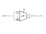
図1を最初に参照すると、本発明の原理による2D撮像プローブでの使用に適したプローブマイクロビーム形成器ASIC10が、ブロック図形式で示される。マイクロビーム形成器の受信機能を単に考慮すれば、ASIC10は、64要素の1Dトランスデューサアレイに結合される64の入力を持つ。マイクロビーム形成器ASICは、64のトランスデューサ要素からの信号を制御可能に遅延させ、16の入力チャネルのグループにそれらを組み合わせる。結果は、部分的にビーム形成された信号の4つの出力である。この例において、各出力は、16のトランスデューサ要素からの信号の組合せである。マイクロビーム形成器ASIC10は、4つの出力チャネルへと64の入力チャネルを減らす。これは、種々の2D撮像プローブに対する便利で標準的なマイクロビーム形成器アーキテクチャを提供する。
Referring initially to FIG. 1, a
図2は、本発明の原理によるシステムミニビーム形成器を持つこの標準的なアーキテクチャの使用を示す。この例において、標準的なマイクロビーム形成器ASIC10a及び10bの2つは、128要素の1Dトランスデューサアレイ16を持つプローブにおいて用いられる。128要素の半分は、ASIC10aの64の入力に結合される。この要素の他の半分は、ASIC10bの64の入力に結合される。プローブからの8つの部分的にビーム形成された出力信号経路が存在する。これは、8導体プローブケーブル18によりシステムメインフレームに結合される。プローブケーブルは、信号がまだアナログ形式の場合8つのアナログ信号導体を持ち、信号がプローブにおいてデジタル化される場合デジタル信号導体を持つことができる。ケーブル18の8つの部分的にビーム形成された信号経路が、システムメインフレームにおけるミニビーム形成器12の8つのチャネルに結合される。ミニビーム形成器12は、グループ遅延で遅延させ、その出力14で完全にビーム形成されたコヒーレントなエコー信号を生成するため8つの信号を組み合わせて、ビーム形成動作処理を完了する。完全にビーム形成された信号は、画像処理及び表示のためシステムメインフレームの後続のアセンブリへと転送されることができる。プローブ及びそのケーブルにおける超音波信号を減らすため同じマイクロビーム形成器ASICを使用することは、多数の利点を提供する。最初に、標準化されたマイクロビーム形成器ASICが、プローブビーム形成を実行するため、複数回モジュール的に用いられることができる。この例において、同じマイクロビーム形成器ASICの2つが用いられる。これは、種々の異なるプローブに適用可能なビーム形成動作に対する標準化された手法を提供する。第2に、このアーキテクチャは、より小さく、より低コスト、低電力の、低チャネル計数メインビーム形成器システム、ミニビーム形成器12を可能にする。これは、この例では8つのチャネルだけを持つ。第3に、複数のプローブモデルにわたり標準的なマイクロビーム形成器に関する共通の回路基板設計の実現は、将来のプローブモデルの迅速な配備を可能にする。第4に、プローブケーブルは、この例では8であるより少数の信号経路だけを搬送する。これは、薄くて軽量でより低コストのケーブルを持つプローブを可能にする。別の有利な特徴は、プローブ及びシステムコネクタにおいて必要とされるピンの数が、システムによりサポートされるアレイ要素の最大数(この例では128の要素)未満とすることができる点にある。これは、コネクタサイズ、コスト及び重みを減らす。
FIG. 2 illustrates the use of this standard architecture with a system mini-beamformer according to the principles of the present invention. In this example, two of the
図3は、160要素の1Dアレイ20に関するマイクロビーム形成器及びミニビーム形成器アーキテクチャの別の実現を示す。前述した同じ標準的なマイクロビーム形成器ASICが、この実現において用いられる。この場合、3つのASICが用いられる。ASIC10a及び10bはそれぞれ、トランスデューサアレイ20の64の要素に結合される。160要素のアレイ20の残りの32の要素は、第3のマイクロビーム形成器ASIC10cの入力チャネルの半分に結合される。第3のASIC10cの半分だけが効果的に用いられるので、その4つの出力の2つだけが用いられる。プローブケーブル18'を用いてプローブからシステムメインフレームまで結合される全部で10の部分的にビーム形成された出力信号経路が存在する。10の部分的にビーム形成された出力信号経路は、最も外側の要素のグループに対応する経路を一緒に接続することにより、8にまで減らされる。従って、それぞれ、センサーアレイの1つの端部における第1及び第2のマイクロビーム形成器出力部が、他端における第9及び第10のマイクロビーム形成器出力部に接続される。一度にアクティブなのは8つの要素のグループを超えない音響アパーチャの部分だけであるので、任意のスキャンライン位置に関して、8つの信号経路だけが必要とされる。マイクロビーム形成器ASIC10a、10b及び10cは、このシステムにより、各スキャンラインに対して、10のサブアレイのわずか8において要素の隣接する範囲を起動させるように構成される。スキャンラインがスキャンされるフレームにわたり進行するとき、起動される要素の範囲は、アクティブ開口にわたりシフトし、対応するマイクロビーム形成器出力部はこれに従って起動される。従って、8つのアナログの信号経路に対して、8つの導電体ケーブル18'で十分である。これらの8つの信号経路は、メインフレーム超音波システムのミニビーム形成器12'の8つの入力部に結合される。これは、その出力部14'で完全にビーム形成されたコヒーレントなエコー信号を提供するため、ビーム形成を完了する。図2の128要素のプローブがミニビーム形成器12'に結合される場合、その8つのアナログの信号経路は、128要素のアレイトランスデューサに関するビーム形成を完了するため、ミニビーム形成器12'の8つの入力チャネルに接続するとき、同じ8つのチャネルケーブルを利用するだろう。同じモジュラマイクロビーム形成器設計の2つの異なるプローブが、同じシステムメインフレームで使用されることができることが分かる。
FIG. 3 illustrates another implementation of a microbeamformer and minibeamformer architecture for a 160
図4は、標準的なマイクロビーム形成器ASICがシステムメインフレームにケーブルを接続するプローブコネクタに配置される2D撮像プローブに関する本発明の別の実現を示す。この例では、プローブ30は、128のトランスデューサ要素のリニアアレイトランスデューサ32を持つ従来のレガシープローブである。アレイの各要素は、128の導電体ケーブル34のそれ自身の導体に結合される。プローブケーブル34は、超音波システムメインフレーム上の嵌合コネクタに接続するプローブコネクタ36でターミネートする。プローブ及びケーブルは、これまでに記載されたように、長年にわたり超音波システムにとって一般に利用可能だった。本発明の原理によれば、プローブ及びケーブルの128の信号経路を8の部分的にビーム形成された出力信号経路へと減らすため、上述の標準的なマイクロビーム形成器ASIC10が、プローブコネクタ36において使用される。128のケーブル信号経路の半分は、1つのマイクロビーム形成器ASICに結合され、他の半分は、他のASICに結合される。システムビーム形成器に結合される合計8つの部分的にビーム形成された信号経路が存在する。ビーム形成処理を完了し、画像を形成するのに適したコヒーレントなエコー信号を生成するため、図4のレガシープローブ構成が、図2のミニビーム形成器12又は図3のミニビーム形成器12'のいずれかと共に使用されることができる。64要素の1Dアレイトランスデューサを用いるレガシープローブは、図1の1つのマイクロビーム形成器10だけを必要とする。ケーブルは、マイクロビーム形成器から受信される部分的にビーム形成された信号に関する4つの信号経路だけを必要とする。
FIG. 4 shows another implementation of the present invention for a 2D imaging probe in which a standard microbeamformer ASIC is placed on a probe connector that connects a cable to the system mainframe. In this example,
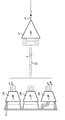
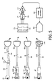
図5は、異なる2D撮像プローブのファミリーを示す。これらの全ては、本発明の原理による減少されたチャネルカウントシステムビーム形成器12と共に作動する。プローブのファミリーは、128要素のタイトカーブアレイ42を持つ経膣プローブ40、192要素のリニアアレイトランスデューサ52を持つリニアアレイプローブ50、128要素のフェーズドアレイトランスデューサ62を持つ心臓撮像のためのフェーズドアレイプローブ60、及び128要素のカーブアレイ32'を持つ分娩撮像に関するレガシーのカーブリニアプローブ30'とを含む。経膣プローブ40は、プローブコネクタ46でターミネートする8つの信号経路ケーブル44を持つ。リニアアレイプローブ50は、プローブコネクタ56でターミネートする8つの信号経路ケーブル54を持ち、共通の信号経路チャネルに対してマイクロビーム形成器出力部を接続する上述した方法を利用する。この場合、アレイにおいてチャネルの外側のグループに仕える2つのマイクロビーム形成器が、一緒に接続されるそれらの出力を持つ。こうして、ケーブルにおける信号経路の四つ組が共有される。フェーズドアレイプローブ60は、プローブコネクタ66でターミネートする8つの信号経路ケーブル64を持つ。レガシーカーブリニアプローブ30'は、プローブコネクタ36でターミネートする従来の128の導電体ケーブル34を持つ。
FIG. 5 shows a different family of 2D imaging probes. All of these work with a reduced channel
同じ標準的なマイクロビーム形成器ASIC10が、これらのプローブのそれぞれと共に使用される。経膣プローブ40に対して、2つのマイクロビーム形成器ASIC10が、経膣プローブのハンドルに配置されるプリント回路基板100に取り付けられる。リニアアレイプローブ50の192要素アレイ52に対して、プリント回路基板100上に3つのマイクロビーム形成器ASIC10がプローブのハンドルにおいて使用される。リニアアレイプローブにおける各ASICは、アレイトランスデューサの192の要素のうちの64に接続される。フェーズドアレイプローブ60の128の要素に対して、プリント回路基板100上の2つのマイクロビーム形成器ASICがプローブのハンドルにおいて使用される。これらのプローブのそれぞれのハンドルは、アレイトランスデューサを含むプローブ要素を備えるケースを有する。レガシーカーブリニアアレイプローブに対して、アレイトランスデューサの128の要素からの128のケーブル導体が、プローブコネクタ36においてプリント回路基板100上の2つのマイクロビーム形成器ASICに結合される。プローブ又はコネクタの内部スペースが許す場合、同じプリント回路基板が各プローブに対して使用されることができる。プローブハンドル又はコネクタ内部の空間が制限される場合、異なるプリント回路基板フォームファクタが、プローブのスペース要件に適合するよう必要に応じて使用される。
The same
ファミリーのプローブの任意の1つ又は全ては、システムメインフレームのプローブコネクタブロック70に配置される同一のシステムプローブコネクタ72に結合されることができる。システムメインフレームは、画像を生み出す任意の超音波システムとすることができる。これは、カート付きシステム及び携帯型システムを含む。複数のプローブが物理的に接続される場合、使用に関してプローブの1つを選択することが必要である。プローブ選択信号PSは、8つのチャネルミニビーム形成器12の入力部に対して選択されたプローブの信号経路及びそのコネクタを結合するマルチプレクサ74に適用される。ミニビーム形成器12は、プローブのマイクロビーム形成器からの8つの部分的にビーム形成された信号のビーム形成を完了し、ミニビーム形成器出力部でのコヒーレントなエコー信号が、画像プロセッサ80に結合され、形成された2D超音波画像が、ディスプレイ90に表示される。
Any one or all of the family of probes can be coupled to the same
プローブファミリーの任意のプローブに対して、システムミニビーム形成器の8つのチャネルで充分である。3つのマイクロビーム形成器ASIC10を使用する192要素リニアアレイプローブ50が選択されるとき、ミニビーム形成器の8つのチャネルは、共通するチャネルの4つを接続することにより、マイクロビーム形成器ASIC10の12の出力部に接続される。上述したように、システムは、マイクロビーム形成器ASICの状態を構成する。その結果、任意のスキャンラインに関して、8つのマイクロビーム形成器出力部の最大だけがアクティブになり、ミニビーム形成器12の8つのチャネル入力部が駆動される。レガシープローブを含む様々な異なるプローブが、本発明のビーム形成器構造と共に使用されることができ、システムビーム形成器は、明らかに減少した数のチャネルを持つことが分かる。サイズ、重み及び複雑さの全てが減らされるので、このアーキテクチャは、カート付き超音波システム及びより小さな携帯型又はハンドヘルドシステムに適している。
For any probe in the probe family, eight channels of the system mini-beamformer are sufficient. When a 192 element
本発明のビーム形成器構造の実現の他の変形が、当業者にとって容易に明らかである。システムミニビーム形成器が12のチャネルまでスケール化される場合、128の要素のシフティングサブアレイとしてではなく、192の要素を同時に起動及びビーム形成するような態様で、4出力の標準化されたマイクロビーム形成器の3つまでを収容することができる。この変形例は、より精細なピッチ要素を持つプローブに関する利点を提供することができる。これは、横方向における画像解像度を増加させる、より大きなビーム形成開口を可能にする。同様に、システムミニビーム形成器が16のチャネルを有する場合、256のトランスデューサ要素が、4つのマイクロビーム形成器ASICを介して同時にビーム形成されることができる。これは、上述された標準的なASICを持つ256までの同時にアクティブとなるトランスデューサ要素を備える2D撮像プローブを可能にする。プローブのファミリーが、128以下の要素を持つトランスジューサセンサアレイを使用する場合、8つのチャネルシステムビーム形成器が、任意のスキャンラインにおけるすべての要素を同時にビーム形成する能力を持つプローブの全体のファミリーを収容することができる。代替的に、64から4より大きなチャネル削減のマイクロビーム形成器が使用されることができる。しかしながら、現在のすべてのプローブだけではなく、将来予想されるプローブに対して使用されることができる標準的なASICを選択することが望ましい。マイクロビーム形成器ASICは、小さなプローブケース内部に適合するコンパクトなアセンブリを形成するよう、トランスデューサアレイスタックに取り付けられるフリップチップとすることができる。トランスデューサアレイスタックは、半導体処理により作られる圧電セラミック(例えば、PZT)アレイ又はCMUT若しくはPMUTマイクロマシン・トランスデューサアレイを有することができる。 Other variations of implementation of the beamformer structure of the present invention will be readily apparent to those skilled in the art. When the system mini-beamformer is scaled to 12 channels, a standardized microbeam with 4 outputs in such a way that 192 elements are activated and beamformed simultaneously rather than as a 128 element shifting sub-array. Up to three formers can be accommodated. This variation can provide advantages for probes with finer pitch elements. This allows for a larger beam forming aperture that increases the image resolution in the lateral direction. Similarly, if the system mini-beamformer has 16 channels, 256 transducer elements can be beamformed simultaneously via 4 microbeamformer ASICs. This allows 2D imaging probes with up to 256 simultaneously active transducer elements with the standard ASICs described above. If the probe family uses a transducer sensor array with 128 or fewer elements, the eight channel system beamformer will allow the entire family of probes to be capable of beamforming all elements simultaneously in any scan line. Can be accommodated. Alternatively, a microbeamformer with a channel reduction greater than 64 to 4 can be used. However, it is desirable to select a standard ASIC that can be used for future probes as well as all current probes. The microbeamformer ASIC can be a flip chip attached to the transducer array stack to form a compact assembly that fits inside a small probe case. The transducer array stack can have a piezoelectric ceramic (eg, PZT) array or a CMUT or PMUT micromachine transducer array made by semiconductor processing.
Claims (16)
異なる臨床応用に関する複数の2D撮像プローブであって、各2D撮像プローブが、アレイトランスデューサを持ち、1つ又は複数の同じマイクロビーム形成器が、前記アレイトランスデューサの要素に結合され、前記1つ又は複数のマイクロビーム形成器が、4から16までの部分的にビーム形成された受信信号を生成する、複数の2D撮像プローブと、
前記部分的にビーム形成された受信信号をメインフレーム超音波システムに結合させるため、前記プローブのそれぞれに結合されるケーブルと、
メインフレーム超音波システムに結合するよう構成される各ケーブルの端にあるコネクタと、
メインフレーム超音波システムとを有し、
前記メインフレーム超音波システムが、
プローブケーブルにより係合するよう構成される嵌合コネクタと、
前記嵌合コネクタからの信号を受信するよう構成されるビーム形成器であって、完全にビーム形成された受信信号を形成するため、部分的にビーム形成された受信信号を処理するための4〜16チャネルを持つ、ビーム形成器と、
前記完全にビーム形成された受信信号に応答する画像プロセッサと、
前記画像プロセッサに結合されるディスプレイとを持つ、超音波診断システム。 An ultrasound diagnostic system for 2D imaging with a family of 2D imaging probes,
A plurality of 2D imaging probes for different clinical applications, each 2D imaging probe having an array transducer and one or more identical microbeamformers coupled to elements of the array transducer, the one or more A plurality of 2D imaging probes for generating 4 to 16 partially beamformed received signals;
A cable coupled to each of the probes for coupling the partially beamformed received signal to a mainframe ultrasound system;
A connector at the end of each cable configured to couple to the mainframe ultrasound system;
A mainframe ultrasound system,
The mainframe ultrasound system is
A mating connector configured to be engaged by a probe cable;
A beamformer configured to receive a signal from the mating connector, 4 to 4 for processing a partially beamformed received signal to form a fully beamformed received signal. A beamformer having 16 channels;
An image processor responsive to the fully beamformed received signal;
An ultrasound diagnostic system having a display coupled to the image processor.
Applications Claiming Priority (3)
| Application Number | Priority Date | Filing Date | Title |
|---|---|---|---|
| US201161503329P | 2011-06-30 | 2011-06-30 | |
| US61/503,329 | 2011-06-30 | ||
| PCT/IB2012/053281 WO2013001484A1 (en) | 2011-06-30 | 2012-06-28 | Two dimensional ultrasonic diagnostic imaging system with two beamformer stages |
Publications (2)
| Publication Number | Publication Date |
|---|---|
| JP2014518124A true JP2014518124A (en) | 2014-07-28 |
| JP2014518124A5 JP2014518124A5 (en) | 2015-07-09 |
Family
ID=46601862
Family Applications (1)
| Application Number | Title | Priority Date | Filing Date |
|---|---|---|---|
| JP2014518031A Pending JP2014518124A (en) | 2011-06-30 | 2012-06-28 | Two-dimensional ultrasonic diagnostic imaging system using two beamformer stages |
Country Status (6)
| Country | Link |
|---|---|
| US (1) | US20140121521A1 (en) |
| EP (1) | EP2726903B1 (en) |
| JP (1) | JP2014518124A (en) |
| CN (1) | CN103635829B (en) |
| BR (1) | BR112013033229A2 (en) |
| WO (1) | WO2013001484A1 (en) |
Cited By (2)
| Publication number | Priority date | Publication date | Assignee | Title |
|---|---|---|---|---|
| JP2018183297A (en) * | 2017-04-24 | 2018-11-22 | コニカミノルタ株式会社 | Ultrasonic diagnostic device and ultrasonic signal processing method |
| JP2022541469A (en) * | 2019-07-15 | 2022-09-26 | 无錫海斯凱尓医学技術有限公司 | Detection mode control circuit |
Families Citing this family (7)
| Publication number | Priority date | Publication date | Assignee | Title |
|---|---|---|---|---|
| RU2638967C2 (en) | 2012-05-09 | 2017-12-19 | Конинклейке Филипс Н.В. | Matrices of ultrasonic converters with variable geometries of surface areas |
| CN103908291A (en) * | 2012-12-28 | 2014-07-09 | Ge医疗系统环球技术有限公司 | Ultrasonic probe switching device and corresponding ultrasonic imaging system |
| KR102107728B1 (en) * | 2013-04-03 | 2020-05-07 | 삼성메디슨 주식회사 | Portable ultrasound apparatus, portable ultrasound system and method for diagnosis using ultrasound |
| US10405829B2 (en) | 2014-12-01 | 2019-09-10 | Clarius Mobile Health Corp. | Ultrasound machine having scalable receive beamformer architecture comprising multiple beamformers with common coefficient generator and related methods |
| US10705210B2 (en) * | 2017-05-31 | 2020-07-07 | B-K Medical Aps | Three-dimensional (3-D) imaging with a row-column addressed (RCA) transducer array using synthetic aperture sequential beamforming (SASB) |
| CN110833432B (en) * | 2018-08-15 | 2023-04-07 | 深南电路股份有限公司 | Ultrasonic simulation front-end device and ultrasonic imaging equipment |
| CN112237444B (en) * | 2020-12-18 | 2021-12-07 | 深圳华声医疗技术股份有限公司 | Control method, control device and medium for ultrasonic imaging system |
Citations (10)
| Publication number | Priority date | Publication date | Assignee | Title |
|---|---|---|---|---|
| JPH01300936A (en) * | 1988-05-30 | 1989-12-05 | Yokogawa Medical Syst Ltd | Ultrasonic diagnostic apparatus |
| JP2002177266A (en) * | 2000-11-09 | 2002-06-25 | Koninkl Philips Electronics Nv | Portable ultrasonic image forming system to be configured |
| US6491634B1 (en) * | 2000-10-13 | 2002-12-10 | Koninklijke Philips Electronics N.V. | Sub-beamforming apparatus and method for a portable ultrasound imaging system |
| JP2005040418A (en) * | 2003-07-24 | 2005-02-17 | Aloka Co Ltd | Ultrasonic diagnostic apparatus |
| US20050148873A1 (en) * | 2003-12-19 | 2005-07-07 | Siemens Medical Solutions Usa, Inc. | Ultrasound adaptor methods and systems for transducer and system separation |
| JP2005261595A (en) * | 2004-03-17 | 2005-09-29 | Aloka Co Ltd | Ultrasonic diagnosis equipment |
| US20070016023A1 (en) * | 2005-06-28 | 2007-01-18 | Siemens Medical Solutions Usa, Inc. | Scalable ultrasound system and methods |
| WO2010055428A1 (en) * | 2008-11-11 | 2010-05-20 | Koninklijke Philips Electronics, N.V. | Configurable microbeamformer circuit for an ultrasonic diagnostic imaging system |
| JP2010136873A (en) * | 2008-12-11 | 2010-06-24 | Toshiba Corp | Ultrasonic diagnostic apparatus and diagnostic image acquiring method using the same |
| JP2010528698A (en) * | 2007-06-01 | 2010-08-26 | コーニンクレッカ フィリップス エレクトロニクス エヌ ヴィ | Wireless ultrasonic probe cable |
Family Cites Families (19)
| Publication number | Priority date | Publication date | Assignee | Title |
|---|---|---|---|---|
| US5229933A (en) | 1989-11-28 | 1993-07-20 | Hewlett-Packard Company | 2-d phased array ultrasound imaging system with distributed phasing |
| US5615678A (en) * | 1994-11-25 | 1997-04-01 | General Electric Company | Integral auto-selecting yoke/transducer connector for ultrasound transducer probe |
| US6203498B1 (en) * | 1996-06-28 | 2001-03-20 | Sonosite, Inc. | Ultrasonic imaging device with integral display |
| DE19741361C1 (en) * | 1997-09-19 | 1999-04-15 | Siemens Ag | Ultrasonic instrument set for medical diagnosis or non |
| US5997479A (en) | 1998-05-28 | 1999-12-07 | Hewlett-Packard Company | Phased array acoustic systems with intra-group processors |
| US6089096A (en) * | 1998-07-01 | 2000-07-18 | Aloka Co., Ltd. | Elevation focusing by beamformer channel sharing |
| US6102863A (en) | 1998-11-20 | 2000-08-15 | Atl Ultrasound | Ultrasonic diagnostic imaging system with thin cable ultrasonic probes |
| US6364839B1 (en) * | 1999-05-04 | 2002-04-02 | Sonosite, Inc. | Ultrasound diagnostic instrument having software in detachable scanhead |
| US6969352B2 (en) * | 1999-06-22 | 2005-11-29 | Teratech Corporation | Ultrasound probe with integrated electronics |
| US7037264B2 (en) | 2000-08-17 | 2006-05-02 | Koninklijke Philips Electronics N.V. | Ultrasonic diagnostic imaging with steered image plane |
| US6602194B2 (en) * | 2000-09-15 | 2003-08-05 | Koninklijke Philips Electronics N.V. | Dual beamformer ultrasound system for 2D and 3D imaging |
| KR100406099B1 (en) * | 2001-09-05 | 2003-11-14 | 주식회사 메디슨 | Ultrasound image forming apparatus and method using multi-level pulse compressor |
| US6500126B1 (en) * | 2001-12-20 | 2002-12-31 | Koninklijke Philips Electronics N.V. | Ultrasound system transducer adapter |
| US6705995B1 (en) | 2002-10-04 | 2004-03-16 | Koninklijke Philips Electronics N.V. | Method and apparatus for 1D array ultrasound probe |
| US20040158154A1 (en) * | 2003-02-06 | 2004-08-12 | Siemens Medical Solutions Usa, Inc. | Portable three dimensional diagnostic ultrasound imaging methods and systems |
| WO2006035384A1 (en) * | 2004-09-30 | 2006-04-06 | Koninklijke Philips Electronics N.V. | Microbeamforming transducer architecture |
| US8002708B2 (en) * | 2005-01-11 | 2011-08-23 | General Electric Company | Ultrasound beamformer with scalable receiver boards |
| WO2006111871A1 (en) * | 2005-04-18 | 2006-10-26 | Koninklijke Philips Electronics N.V. | Portable ultrasonic diagnostic imaging system with docking station |
| US8043221B2 (en) * | 2007-08-17 | 2011-10-25 | General Electric Company | Multi-headed imaging probe and imaging system using same |
-
2012
- 2012-06-28 JP JP2014518031A patent/JP2014518124A/en active Pending
- 2012-06-28 WO PCT/IB2012/053281 patent/WO2013001484A1/en active Application Filing
- 2012-06-28 CN CN201280032471.XA patent/CN103635829B/en active Active
- 2012-06-28 BR BR112013033229A patent/BR112013033229A2/en not_active IP Right Cessation
- 2012-06-28 US US14/123,995 patent/US20140121521A1/en not_active Abandoned
- 2012-06-28 EP EP12741385.4A patent/EP2726903B1/en active Active
Patent Citations (10)
| Publication number | Priority date | Publication date | Assignee | Title |
|---|---|---|---|---|
| JPH01300936A (en) * | 1988-05-30 | 1989-12-05 | Yokogawa Medical Syst Ltd | Ultrasonic diagnostic apparatus |
| US6491634B1 (en) * | 2000-10-13 | 2002-12-10 | Koninklijke Philips Electronics N.V. | Sub-beamforming apparatus and method for a portable ultrasound imaging system |
| JP2002177266A (en) * | 2000-11-09 | 2002-06-25 | Koninkl Philips Electronics Nv | Portable ultrasonic image forming system to be configured |
| JP2005040418A (en) * | 2003-07-24 | 2005-02-17 | Aloka Co Ltd | Ultrasonic diagnostic apparatus |
| US20050148873A1 (en) * | 2003-12-19 | 2005-07-07 | Siemens Medical Solutions Usa, Inc. | Ultrasound adaptor methods and systems for transducer and system separation |
| JP2005261595A (en) * | 2004-03-17 | 2005-09-29 | Aloka Co Ltd | Ultrasonic diagnosis equipment |
| US20070016023A1 (en) * | 2005-06-28 | 2007-01-18 | Siemens Medical Solutions Usa, Inc. | Scalable ultrasound system and methods |
| JP2010528698A (en) * | 2007-06-01 | 2010-08-26 | コーニンクレッカ フィリップス エレクトロニクス エヌ ヴィ | Wireless ultrasonic probe cable |
| WO2010055428A1 (en) * | 2008-11-11 | 2010-05-20 | Koninklijke Philips Electronics, N.V. | Configurable microbeamformer circuit for an ultrasonic diagnostic imaging system |
| JP2010136873A (en) * | 2008-12-11 | 2010-06-24 | Toshiba Corp | Ultrasonic diagnostic apparatus and diagnostic image acquiring method using the same |
Cited By (3)
| Publication number | Priority date | Publication date | Assignee | Title |
|---|---|---|---|---|
| JP2018183297A (en) * | 2017-04-24 | 2018-11-22 | コニカミノルタ株式会社 | Ultrasonic diagnostic device and ultrasonic signal processing method |
| JP2022541469A (en) * | 2019-07-15 | 2022-09-26 | 无錫海斯凱尓医学技術有限公司 | Detection mode control circuit |
| JP7393828B2 (en) | 2019-07-15 | 2023-12-07 | 无錫海斯凱尓医学技術有限公司 | Detection mode control circuit |
Also Published As
| Publication number | Publication date |
|---|---|
| WO2013001484A1 (en) | 2013-01-03 |
| US20140121521A1 (en) | 2014-05-01 |
| BR112013033229A2 (en) | 2017-03-01 |
| EP2726903A1 (en) | 2014-05-07 |
| EP2726903B1 (en) | 2018-08-08 |
| CN103635829A (en) | 2014-03-12 |
| CN103635829B (en) | 2016-04-27 |
Similar Documents
| Publication | Publication Date | Title |
|---|---|---|
| EP2726903B1 (en) | Two dimensional ultrasonic diagnostic imaging system with two beamformer stages | |
| US11559277B2 (en) | Ultrasound 3D imaging system | |
| CN100337594C (en) | Supersonic array transducer receiver for handheld supersonic diagnosis instrument | |
| US6183419B1 (en) | Multiplexed array transducers with improved far-field performance | |
| US8551000B2 (en) | Ultrasound 3D imaging system | |
| JP3090718B2 (en) | Ultrasound diagnostic equipment | |
| US7963919B2 (en) | Ultrasound imaging transducer array for synthetic aperture | |
| US9983176B2 (en) | Two dimensional ultrasound transducer arrays operable with different ultrasound systems | |
| JP2008514335A (en) | Transducer structure for microbeam formation | |
| US20080294050A1 (en) | Ultrasonic Imaging Apparatus | |
| US20120179044A1 (en) | Ultrasound 3d imaging system | |
| US20110213251A1 (en) | Configurable microbeamformer circuit for an ultrasonic diagnostic imaging system | |
| US6821251B2 (en) | Multiplexer for connecting a multi-row ultrasound transducer array to a beamformer | |
| JP3977827B2 (en) | Ultrasonic diagnostic equipment | |
| WO2010031057A1 (en) | Ultrasound 3d imaging system | |
| JP6960938B2 (en) | 2D ultrasonic array transducer with 1D patch | |
| JP4624756B2 (en) | Ultrasonic diagnostic equipment | |
| Kruizinga et al. | Towards 3D ultrasound imaging of the carotid artery using a programmable and tileable matrix array | |
| JP3256698B2 (en) | Ultrasound diagnostic equipment | |
| US12102479B2 (en) | Ultrasound 3D imaging system | |
| US20230346344A1 (en) | Ultrasound 3d imaging system | |
| JP2005143838A (en) | Ultrasonograph | |
| JP2011010827A (en) | Ultrasonic wave probe and ultrasonic diagnostic device |
Legal Events
| Date | Code | Title | Description |
|---|---|---|---|
| A521 | Request for written amendment filed |
Free format text: JAPANESE INTERMEDIATE CODE: A523 Effective date: 20150520 |
|
| A621 | Written request for application examination |
Free format text: JAPANESE INTERMEDIATE CODE: A621 Effective date: 20150520 |
|
| A977 | Report on retrieval |
Free format text: JAPANESE INTERMEDIATE CODE: A971007 Effective date: 20160323 |
|
| A131 | Notification of reasons for refusal |
Free format text: JAPANESE INTERMEDIATE CODE: A131 Effective date: 20160426 |
|
| A521 | Request for written amendment filed |
Free format text: JAPANESE INTERMEDIATE CODE: A523 Effective date: 20160725 |
|
| A131 | Notification of reasons for refusal |
Free format text: JAPANESE INTERMEDIATE CODE: A131 Effective date: 20161222 |
|
| RD04 | Notification of resignation of power of attorney |
Free format text: JAPANESE INTERMEDIATE CODE: A7424 Effective date: 20170214 |
|
| A601 | Written request for extension of time |
Free format text: JAPANESE INTERMEDIATE CODE: A601 Effective date: 20170317 |
|
| A521 | Request for written amendment filed |
Free format text: JAPANESE INTERMEDIATE CODE: A523 Effective date: 20170620 |
|
| A02 | Decision of refusal |
Free format text: JAPANESE INTERMEDIATE CODE: A02 Effective date: 20171124 |
|
| A521 | Request for written amendment filed |
Free format text: JAPANESE INTERMEDIATE CODE: A523 Effective date: 20180323 |
|
| A911 | Transfer to examiner for re-examination before appeal (zenchi) |
Free format text: JAPANESE INTERMEDIATE CODE: A911 Effective date: 20180330 |
|
| A912 | Re-examination (zenchi) completed and case transferred to appeal board |
Free format text: JAPANESE INTERMEDIATE CODE: A912 Effective date: 20180518 |