JP2014517907A - Reference markers for starting point identification in optical shape detection systems - Google Patents
Reference markers for starting point identification in optical shape detection systems Download PDFInfo
- Publication number
- JP2014517907A JP2014517907A JP2013550983A JP2013550983A JP2014517907A JP 2014517907 A JP2014517907 A JP 2014517907A JP 2013550983 A JP2013550983 A JP 2013550983A JP 2013550983 A JP2013550983 A JP 2013550983A JP 2014517907 A JP2014517907 A JP 2014517907A
- Authority
- JP
- Japan
- Prior art keywords
- coordinate system
- optical fiber
- start point
- optical
- reconstruction
- Prior art date
- Legal status (The legal status is an assumption and is not a legal conclusion. Google has not performed a legal analysis and makes no representation as to the accuracy of the status listed.)
- Pending
Links
- 230000003287 optical effect Effects 0.000 title claims abstract description 64
- 238000001514 detection method Methods 0.000 title claims abstract description 49
- 239000013307 optical fiber Substances 0.000 claims abstract description 65
- 239000003550 marker Substances 0.000 claims abstract description 45
- 238000003384 imaging method Methods 0.000 claims description 9
- 230000033001 locomotion Effects 0.000 claims description 5
- 239000000835 fiber Substances 0.000 description 9
- 238000012544 monitoring process Methods 0.000 description 6
- 238000000034 method Methods 0.000 description 4
- 239000011521 glass Substances 0.000 description 2
- 230000004807 localization Effects 0.000 description 2
- 238000012986 modification Methods 0.000 description 2
- 230000004048 modification Effects 0.000 description 2
- 230000002285 radioactive effect Effects 0.000 description 2
- 230000035945 sensitivity Effects 0.000 description 2
- 238000002603 single-photon emission computed tomography Methods 0.000 description 2
- ZCYVEMRRCGMTRW-UHFFFAOYSA-N 7553-56-2 Chemical compound [I] ZCYVEMRRCGMTRW-UHFFFAOYSA-N 0.000 description 1
- 238000009530 blood pressure measurement Methods 0.000 description 1
- 238000002608 intravascular ultrasound Methods 0.000 description 1
- 229910052740 iodine Inorganic materials 0.000 description 1
- 239000011630 iodine Substances 0.000 description 1
- 238000005259 measurement Methods 0.000 description 1
- 238000012978 minimally invasive surgical procedure Methods 0.000 description 1
- 238000001356 surgical procedure Methods 0.000 description 1
- 238000002604 ultrasonography Methods 0.000 description 1
Images


Classifications
-
- G—PHYSICS
- G01—MEASURING; TESTING
- G01B—MEASURING LENGTH, THICKNESS OR SIMILAR LINEAR DIMENSIONS; MEASURING ANGLES; MEASURING AREAS; MEASURING IRREGULARITIES OF SURFACES OR CONTOURS
- G01B11/00—Measuring arrangements characterised by the use of optical techniques
- G01B11/16—Measuring arrangements characterised by the use of optical techniques for measuring the deformation in a solid, e.g. optical strain gauge
- G01B11/165—Measuring arrangements characterised by the use of optical techniques for measuring the deformation in a solid, e.g. optical strain gauge by means of a grating deformed by the object
-
- A—HUMAN NECESSITIES
- A61—MEDICAL OR VETERINARY SCIENCE; HYGIENE
- A61B—DIAGNOSIS; SURGERY; IDENTIFICATION
- A61B5/00—Measuring for diagnostic purposes; Identification of persons
- A61B5/06—Devices, other than using radiation, for detecting or locating foreign bodies ; determining position of probes within or on the body of the patient
- A61B5/061—Determining position of a probe within the body employing means separate from the probe, e.g. sensing internal probe position employing impedance electrodes on the surface of the body
- A61B5/064—Determining position of a probe within the body employing means separate from the probe, e.g. sensing internal probe position employing impedance electrodes on the surface of the body using markers
-
- A—HUMAN NECESSITIES
- A61—MEDICAL OR VETERINARY SCIENCE; HYGIENE
- A61B—DIAGNOSIS; SURGERY; IDENTIFICATION
- A61B34/00—Computer-aided surgery; Manipulators or robots specially adapted for use in surgery
- A61B34/20—Surgical navigation systems; Devices for tracking or guiding surgical instruments, e.g. for frameless stereotaxis
-
- G—PHYSICS
- G01—MEASURING; TESTING
- G01B—MEASURING LENGTH, THICKNESS OR SIMILAR LINEAR DIMENSIONS; MEASURING ANGLES; MEASURING AREAS; MEASURING IRREGULARITIES OF SURFACES OR CONTOURS
- G01B11/00—Measuring arrangements characterised by the use of optical techniques
- G01B11/16—Measuring arrangements characterised by the use of optical techniques for measuring the deformation in a solid, e.g. optical strain gauge
- G01B11/18—Measuring arrangements characterised by the use of optical techniques for measuring the deformation in a solid, e.g. optical strain gauge using photoelastic elements
-
- A—HUMAN NECESSITIES
- A61—MEDICAL OR VETERINARY SCIENCE; HYGIENE
- A61B—DIAGNOSIS; SURGERY; IDENTIFICATION
- A61B34/00—Computer-aided surgery; Manipulators or robots specially adapted for use in surgery
- A61B34/20—Surgical navigation systems; Devices for tracking or guiding surgical instruments, e.g. for frameless stereotaxis
- A61B2034/2046—Tracking techniques
- A61B2034/2061—Tracking techniques using shape-sensors, e.g. fiber shape sensors with Bragg gratings
Abstract
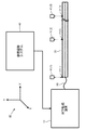
光学ファイバ20及び1つ又は複数の参照マーカー41を使用する光学形状検出システムが提供される。各参照マーカー41は、参照座標系42における特定可能な参照追跡位置を持つ。光学ファイバ20は、上記参照座標系42における上記光学ファイバ20の形状再構成の実行に関する基礎として機能する上記参照座標系42における再構成開始ポイント21を持つ。上記光学ファイバ20の再構成開始ポイント21は、上記参照座標系42における上記再構成開始ポイント21の特定を容易にするため、各参照マーカー41と既知の空間関係を持つ。 An optical shape detection system using the optical fiber 20 and one or more reference markers 41 is provided. Each reference marker 41 has an identifiable reference tracking position in the reference coordinate system 42. The optical fiber 20 has a reconstruction start point 21 in the reference coordinate system 42 that serves as a basis for performing the shape reconstruction of the optical fiber 20 in the reference coordinate system 42. The reconstruction start point 21 of the optical fiber 20 has a known spatial relationship with each reference marker 41 to facilitate the identification of the reconstruction start point 21 in the reference coordinate system 42.
Description
本発明は一般に、光学ファイバの形状再構成に関する。より詳細には、本発明は、光学ファイバの正確な形状再構成のための開始ポイントの信頼性が高い特定に関する。 The present invention generally relates to optical fiber shape reconstruction. More particularly, the present invention relates to the reliable identification of the starting point for accurate shape reconstruction of an optical fiber.
従来技術において既知の光学形状検出システムは、光学形状検出システムが、リアルタイムな態様で、内視鏡、カテーテル又はガイドワイヤといったデバイス内で囲まれる光学ファイバの形状を表示する可能性があることから、今日介入的な環境において実行される最小侵襲的手術手順に革命をもたらし、これを変化させる能力を持つ。 Optical shape detection systems known in the prior art may display the shape of the optical fiber enclosed in a device such as an endoscope, catheter or guidewire in a real-time manner. It has the ability to revolutionize and change minimally invasive surgical procedures performed in interventional environments today.
しかしながら、これらの光学ファイバは、正確な形状再構成のため既知の参照位置から開始されることを必要とする。 However, these optical fibers need to be started from a known reference position for accurate shape reconstruction.
特に、光学ファイバの形状再構成は、以下の式
![]()
![]()
![]()
![]()
![]()
![]()
![]()
![]()
![]()
![]()
![]()
![]()
光学ファイバの正確な開始ポイントについての知識は従って、正確な形状再構成にとって重要である。本発明は、参照マーカー(例えば、電磁気参照マーカー、光学参照マーカー、放射性参照マーカー等)を使用することにより、1つ又は複数の開始ポイントを特定する光学形状検出システムを提供する。 Knowledge of the exact starting point of the optical fiber is therefore important for accurate shape reconstruction. The present invention provides an optical shape detection system that identifies one or more starting points by using reference markers (eg, electromagnetic reference markers, optical reference markers, radioactive reference markers, etc.).
更に、現在の光学形状検出システムにおいて、開始ポイントの位置に変化がある場合、形状再構成は失敗するだろう。本発明の光学形状検出システムは、初めて、開始ポイントの位置における変化の検出と、その後続の補償とを可能にする。 Furthermore, shape reconstruction will fail if there is a change in the position of the starting point in current optical shape detection systems. For the first time, the optical shape detection system of the present invention allows detection of a change in the position of the starting point and subsequent compensation thereof.
追加的に、光学検出形状、電磁気追跡及び光学追跡といった異なる追跡技術を結合することにより、本発明の光学形状検出システムは、これらの技術の固有の限界を克服する。限界とは、例えば、電磁気追跡のフィールド歪みに対する感度、光学追跡のラインオブサイト限界、及び温度及び圧力/振動ベースの変動に対する光学検出形状の感度である。 Additionally, by combining different tracking techniques such as optical detection shape, electromagnetic tracking and optical tracking, the optical shape detection system of the present invention overcomes the inherent limitations of these techniques. Limits are, for example, sensitivity to field distortions of electromagnetic tracking, line of sight limits of optical tracking, and sensitivity of optical sensing shapes to temperature and pressure / vibration based variations.
本発明の1つの形式は、光学ファイバ及び1つ又は複数の参照マーカーを使用する光学形状検出システムである。各参照マーカーは、参照座標系における特定可能な参照追跡位置及び特定可能な参照追跡方向の一方又は両方を持つ。光学ファイバは、参照座標系における光学ファイバの形状再構成の実行に関する基礎として機能する、参照座標系における再構成開始ポイントを持つ。光学ファイバの再構成開始ポイントは、参照座標系における再構成開始ポイントの特定を容易にするため、各参照マーカーと既知の空間関係を持つ。 One form of the invention is an optical shape detection system that uses optical fibers and one or more reference markers. Each reference marker has one or both of an identifiable reference tracking position and an identifiable reference tracking direction in the reference coordinate system. The optical fiber has a reconstruction start point in the reference coordinate system that serves as the basis for performing optical fiber shape reconstruction in the reference coordinate system. The optical fiber reconstruction start point has a known spatial relationship with each reference marker to facilitate the identification of the reconstruction start point in the reference coordinate system.
本発明の第2の形式は、光学形状検出方法であり、この方法は、参照座標系における各参照マーカーに対する特定可能な参照追跡位置及び特定可能な参照追跡方向の1つ又は両方を特定するステップと、参照座標系における光学ファイバの再構成開始ポイントを特定するステップであって、上記光学ファイバの上記再構成開始ポイントが、上記参照座標系における上記再構成開始ポイントの特定を可能にするため、各参照マーカーと既知の空間関係を持つ、ステップとを含む。この光学形状検出方法は更に、上記参照座標系における上記再構成開始ポイントの特定に基づき、上記参照座標系における上記光学ファイバの形状再構成を実行するステップを含む。 A second form of the present invention is an optical shape detection method that identifies one or both of an identifiable reference tracking position and an identifiable reference tracking direction for each reference marker in a reference coordinate system. And identifying the reconstruction start point of the optical fiber in the reference coordinate system, wherein the reconstruction start point of the optical fiber enables the identification of the reconstruction start point in the reference coordinate system, Each reference marker and a step having a known spatial relationship. The optical shape detection method further includes the step of performing shape reconstruction of the optical fiber in the reference coordinate system based on the specification of the reconstruction start point in the reference coordinate system.
本発明の前述及び他の形式並びに本発明の様々な特徴及び効果が、添付の図面と共に、本発明の様々な例示的な実施形態の以下の詳細な説明から更に明らかになる。詳細な説明及び図面は、本発明を限定するものではなく、単に説明するものである。本発明の範囲は、添付の特許請求の範囲及びその均等の範囲によって規定される。 The foregoing and other forms of the invention and various features and advantages of the invention will become more apparent from the following detailed description of various exemplary embodiments of the invention, along with the accompanying drawings. The detailed description and drawings are merely illustrative of the invention rather than limiting. The scope of the present invention is defined by the appended claims and their equivalents.
図1に示されるように、本発明の光学形状検出システムは、細長いデバイス20に埋め込まれる光学ファイバ10を使用する。
As shown in FIG. 1, the optical shape detection system of the present invention uses an
実際には、光学ファイバ10は、細長いデバイス20を光学的に追跡するのに適した任意のタイプの光学ファイバとすることができる。光学ファイバ10の例は、以下に限定されるものではないが、従来において知られるファイバの長さに沿って一体化されるファイバーブラッグ格子のアレイを組み込む柔軟で光学的に透過的なガラス又はプラスチックファイバー、及び、従来において知られるファイバ(例えば、レイリー散乱ベースの光学ファイバ)の長さに沿って発生するその光学屈折率における自然な変動を持つ、柔軟で光学的に透過的なガラス又はプラスチックファイバーを含む。光学ファイバ10は、単一のコアファイバー、又は好ましくは、マルチコアファイバーとすることができる。
In practice, the
実際には、細長いデバイス20は、細長いデバイス20を光学的に追跡するため光学ファイバ10を埋め込むのに適した任意のタイプのデバイスとすることができる。細長いデバイス20の例は、内視鏡、カテーテル及びガイドワイヤを含むが、これに限定されるものではない。
In practice, the
なお図1を参照すると、システムは更に、光学監視端末10及び参照追跡システム40を使用する。
Still referring to FIG. 1, the system further uses an
実際には、光学監視端末10は、光学ファイバ20へ光を送信し、及び光学ファイバ20から反射された光を受信するよう構造的に構成される任意のデバイス又はシステムとすることができる。ある実施形態では、光学監視端末10は、従来において知られる光学フーリエドメイン反射計及び他の適切な電子部品/デバイスを使用する。
In practice, the
実際には、参照追跡システム40は、参照マーカー41を使用する任意のタイプの撮像誘導システムとして、本書において広く規定される。各参照マーカー41は、参照座標系42を用いて、参照追跡位置及び/又は参照追跡方向を持つ。
In practice, the
ある実施形態では、参照追跡システム40は、電磁気追跡端末、磁場生成器及びセンサコイルの形の参照マーカー41を使用する電磁気追跡システムである。
In one embodiment, the
第2の実施形態において、参照追跡システム40は、光学追跡端末と、アクティブ発光ダイオード又は受動的な球体の形の参照マーカー41とを使用する光学追跡システムである。
In a second embodiment, the
第3の実施形態において、参照追跡システム40は、参照座標系42内の撮像光学ファイバ20に関する撮像モダリティを使用する撮像追跡システムである。従来技術において知られる撮像追跡システムの例は、以下に限定されるものではないが、X線システム、MRIシステム、CTシステム、超音波システム、IVUSシステム、PETシステム、SPECTシステム又はこれらの組み合わせを含む。
In the third embodiment, the
実際には、参照マーカー41の形式は、撮像追跡システムのタイプに依存する。例えば、参照マーカー41は、X線画像において見えるヨウ素ベースのマーカーとすることができる。追加的な例により、参照マーカー41は、核ベースの撮像追跡システム(例えば、PETシステム又はSPECTシステム)において特定可能な放射性又は放射線不透過性マークとすることができる。
In practice, the format of the
光学監視端末10は更に、例えば、図1に示される再構成開始ポイント21といった再構成開始ポイントに対する光学ファイバ20の形状を再構成するための、従来において知られる形状再構成アルゴリズムを使用する。再構成開始ポイント21(1)は、従来において知られる光学ファイバ20の全体の形状再構成の基礎として機能する。一方、開始ポイント21(2)及び21(3)は、従来において知られる光学ファイバ20の異なるセグメントの形状再構成の基礎として機能する。
The
各再構成開始ポイント21に対する1つ又は複数の参照マーカー41の双方向矢印により示されるように、本発明は、既知の空間関係(例えば、既知の距離及び/又は角方向)を前提とする。これにより、参照座標系42における参照マーカー41の参照追跡位置及び/又は参照追跡方向の特定が、参照座標系42における再構成開始ポイント21の特定を可能にする。
The present invention assumes a known spatial relationship (eg, known distance and / or angular direction), as indicated by the double arrow of one or
より詳細には、動作において、参照追跡システム40は、参照座標系42における各参照マーカー41の参照追跡位置及び/又は参照追跡方向を特定する。これは、参照座標系42における光学ファイバ20に関する1つ又は複数の再構成開始ポイント21を特定するために利用される。その後、追跡手順が完了するまで、又は、参照追跡システム40が、参照座標系42における1つ又は複数の参照マーカー41の動きを伝達するまで、光学監視端末10は、光学ファイバ20の形状再構成を実行する。後者の場合、参照追跡システムは、参照座標系42における各参照マーカー41の新しい参照追跡位置及び/又は参照追跡方向を再特定する。これは、参照座標系42における光学ファイバ20に関する1つ又は複数の再構成開始ポイント21を再特定するために利用される。その後、追跡手順が完了するまで、又は、参照追跡システム40が、参照座標系42における1つ又は複数の参照マーカー41及び光学ファイバ20の別の運動を伝達するまで、光学監視端末10は、光学ファイバ20の形状再構成を再実行する。
More specifically, in operation, the
実際には、複数の再構成開始ポイントを持つ実施形態に関して、特定の再構成開始ポイント21が、様々な手段により選択されることができる。例えば、再構成開始ポイント22は、表示されることができる。これにより、システムのユーザは、再構成開始ポイント22の1つを選択することができる。
In fact, for embodiments with multiple reconstruction start points, a particular reconstruction start
図2〜図5は、本発明による光学形状検出デバイスの様々な実施形態を示す。 2-5 illustrate various embodiments of an optical shape detection device according to the present invention.
図2に示されるように、光学形状検出デバイス50は、光学コイル20に関する細長いデバイス51及びハンドル52(例えば、カテーテル及びカテーテルハンドル)を使用する。この実施形態において、参照マーカー41は、図示されるように細長いデバイス51に埋め込まれ、参照マーカー41及び再構成開始ポイント21の空間関係は、既知である。
As shown in FIG. 2, the optical
図3に示されるように、光学形状検出デバイス53は、光学コイル20に関する細長いデバイス54及びハンドル55を使用する。この実施形態において、自由度6のマーカー41が、ハンドル55に埋め込まれ、参照マーカー41及び再構成開始ポイント21の空間関係は、既知である。
As shown in FIG. 3, the optical shape detection device 53 uses an
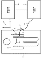
図4に示されるように、光学形状検出デバイスは、患者60を支持する動作テーブル61に取り付けられるプラットフォーム62を使用する。この実施形態において、参照マーカー41は、プラットフォーム62につけられ又はこれに埋め込まれ、光学ファイバ20は、再構成開始ポイント21で細長いデバイス63に埋め込まれる。更に、参照マーカー41及び再構成開始ポイント21の空間関係は、既知である。
As shown in FIG. 4, the optical shape detection device uses a
図5に示されるように、光学形状検出デバイスは、X線システムのC―アーム64に結合されるプラットフォーム65を使用する。この実施形態において、参照マーカー41は、プラットフォーム65につけられ、光学ファイバ20は、再構成開始ポイント21で細長いデバイス66に埋め込まれる。更に、参照マーカー41及び再構成開始ポイント21の空間関係は、既知である。
As shown in FIG. 5, the optical shape detection device uses a
図1〜図5の説明から、当業者は、多数の手術手順に対して本発明による光学形状検出システムを製造及び使用する方法に関して追加的な認識を持つであろう。 From the description of FIGS. 1-5, those skilled in the art will have additional recognition regarding how to make and use the optical shape detection system according to the present invention for a number of surgical procedures.
本発明の様々な例示的な実施形態が図示及び記載されてきたが、本書において記載される本発明の例示的な実施形態が、説明的なものであること、さまざまな変更及び修正がなされることができること、及び本発明の真の範囲から逸脱することなく均等物がその要素に対して置換されることができることは当業者であればよく理解されているだろう。例えば、本発明は、本書においてFBGに関して説明されるが、一般に形状検出又はローカライゼーションに関する光ファィバを含むことを理解されたい。これは、例えば、FBG又は他の光学機器の存在の有無にかかわらず、後方散乱、光学ファイバフォース検出(optical fiber force sensing)、ファイバ位置センサ又はレイリー散乱を用いて、ファイバにおける1つ又は複数の断面における変動の検出又はこの検出からのローカライゼーションを含む。更に、その中心の範囲から逸脱しない範囲で本発明の教示に適合する多くの変形例がなされることができる。従って、本発明は、本発明を実行するために想定されるベストモードとして開示される特定の実施形態に限定されるものではなく、本発明は、添付の特許請求の範囲に含まれるすべての実施形態を含むものである。 While various exemplary embodiments of the present invention have been illustrated and described, the exemplary embodiments of the present invention described herein are illustrative and various changes and modifications may be made. Those skilled in the art will appreciate that what can be done and that equivalents can be substituted for the elements without departing from the true scope of the invention. For example, although the invention is described herein with respect to FBGs, it should be understood that it generally includes optical fibers for shape detection or localization. This can be done, for example, using backscattering, optical fiber force sensing, fiber position sensor or Rayleigh scattering, with or without the presence of FBG or other optical equipment. Includes detection of variations in cross-section or localization from this detection. In addition, many modifications may be made that conform to the teachings of the invention without departing from the central scope thereof. Accordingly, the invention is not limited to the specific embodiments disclosed as the best mode contemplated for carrying out the invention, but the invention includes all implementations within the scope of the appended claims. Includes form.
Claims (20)
光学ファイバと、
少なくとも1つの参照マーカーとを有し、
各参照マーカーが、参照座標系における特定可能な参照追跡位置及び特定可能な参照追跡方向の少なくとも1つを持ち、
前記光学ファイバは、前記参照座標系における前記光学ファイバの形状再構成の実行に関する基礎として機能する、前記参照座標系における再構成開始ポイントを持ち、
前記光学ファイバの前記再構成開始ポイントが、前記参照座標系における前記再構成開始ポイントの特定を容易にするため、各参照マーカーと既知の空間関係を持つ、光学形状検出システム。 An optical shape detection system,
Optical fiber,
Having at least one reference marker;
Each reference marker has at least one of an identifiable reference tracking position and an identifiable reference tracking direction in a reference coordinate system;
The optical fiber has a reconstruction start point in the reference coordinate system that serves as a basis for performing shape reconstruction of the optical fiber in the reference coordinate system;
The optical shape detection system, wherein the reconstruction start point of the optical fiber has a known spatial relationship with each reference marker to facilitate identification of the reconstruction start point in the reference coordinate system.
前記光学ファイバが、前記細長いデバイスに埋め込まれ、前記少なくとも1つの参照マーカーは、前記細長いデバイスから間隔を置いて配置される、請求項1の光学形状検出システム。 Further comprising an elongated device;
The optical shape detection system of claim 1, wherein the optical fiber is embedded in the elongate device and the at least one reference marker is spaced from the elongate device.
前記光学ファイバ及び前記少なくとも1つの参照マーカーが、前記細長いデバイスに埋め込まれる、請求項1の光学形状検出システム。 Further comprising an elongated device;
The optical shape detection system of claim 1, wherein the optical fiber and the at least one reference marker are embedded in the elongate device.
各再構成開始ポイントは、前記参照座標系における前記光学ファイバの形状再構成の実行に関する基礎として機能するよう動作可能であり、
前記光学ファイバの各再構成開始ポイントが、前記参照座標系における前記再構成開始ポイントの特定を容易にするため、各参照マーカーと既知の空間関係を持つ、請求項1の光学形状検出システム。 The optical fiber has a plurality of reconstruction start points in the reference coordinate system;
Each reconstruction start point is operable to serve as a basis for performing shape reconstruction of the optical fiber in the reference coordinate system;
The optical shape detection system of claim 1, wherein each reconstruction start point of the optical fiber has a known spatial relationship with each reference marker to facilitate identification of the reconstruction start point in the reference coordinate system.
参照座標系における各参照マーカーに対する特定可能な参照追跡位置及び特定可能な参照追跡方向の少なくとも1つを特定するステップと、
前記参照座標系における前記光学ファイバの再構成開始ポイントを特定するステップであって、前記光学ファイバの前記再構成開始ポイントが、前記参照座標系における前記再構成開始ポイントの特定を可能にするため、各参照マーカーと既知の空間関係を持つ、ステップと、
前記参照座標系における前記再構成開始ポイントの特定に基づき、前記参照座標系における前記光学ファイバの形状再構成を実行するステップとを有する、方法。 In an optical shape detection method for an optical shape detection system comprising an optical fiber and at least one reference marker,
Identifying at least one of an identifiable reference tracking position and an identifiable reference tracking direction for each reference marker in a reference coordinate system;
Identifying a reconstruction start point of the optical fiber in the reference coordinate system, wherein the reconstruction start point of the optical fiber enables identification of the reconstruction start point in the reference coordinate system; A step having a known spatial relationship with each reference marker;
Performing a shape reconstruction of the optical fiber in the reference coordinate system based on the identification of the reconstruction start point in the reference coordinate system.
参照座標系における各参照マーカーに対する特定可能な参照追跡位置及び特定可能な参照追跡方向の少なくとも1つを再特定するステップと、
前記参照座標系における光学ファイバの再構成開始ポイントを再特定するステップであって、前記光学ファイバの前記再構成開始ポイントが、前記参照座標系における前記再構成開始ポイントの再特定を可能にするため、各参照マーカーと既知の空間関係を持つ、ステップと、
前記参照座標系における前記再構成開始ポイントの前記再特定に基づき、前記参照座標系における前記光学ファイバの形状再構成を実行するステップとを更に有する、請求項16の光学形状検出方法。 Moving the at least one reference marker and the optical fiber in the reference coordinate system while maintaining the known spatial relationship between the reconstruction start point of the optical fiber and each reference marker;
Re-identifying at least one of an identifiable reference tracking position and an identifiable reference tracking direction for each reference marker in the reference coordinate system;
Re-specifying the reconstruction start point of the optical fiber in the reference coordinate system, wherein the reconstruction start point of the optical fiber enables re-identification of the reconstruction start point in the reference coordinate system A step with a known spatial relationship to each reference marker, and
The optical shape detection method according to claim 16, further comprising: performing shape reconstruction of the optical fiber in the reference coordinate system based on the re-specification of the reconstruction start point in the reference coordinate system.
前記参照座標系における前記光学ファイバ及び前記少なくとも1つの参照マーカーの少なくとも一方の前記検出された運動を示すフィードバックを提供するステップとを更に有する、請求項16の光学形状検出方法。 Detecting the movement of at least one of the optical fiber and the at least one reference marker in the reference coordinate system following identification of the reconstruction start point of the optical fiber in the reference coordinate system;
17. The optical shape detection method of claim 16, further comprising providing feedback indicating the detected movement of at least one of the optical fiber and the at least one reference marker in the reference coordinate system.
Applications Claiming Priority (3)
| Application Number | Priority Date | Filing Date | Title |
|---|---|---|---|
| US201161437160P | 2011-01-28 | 2011-01-28 | |
| US61/437,160 | 2011-01-28 | ||
| PCT/IB2012/050321 WO2012101575A1 (en) | 2011-01-28 | 2012-01-24 | Reference markers for launch point identification in optical shape sensing systems |
Related Child Applications (1)
| Application Number | Title | Priority Date | Filing Date |
|---|---|---|---|
| JP2017235793A Division JP6655594B2 (en) | 2011-01-28 | 2017-12-08 | Reference markers for identifying starting points in optical shape detection systems |
Publications (2)
| Publication Number | Publication Date |
|---|---|
| JP2014517907A true JP2014517907A (en) | 2014-07-24 |
| JP2014517907A5 JP2014517907A5 (en) | 2015-03-05 |
Family
ID=45774278
Family Applications (2)
| Application Number | Title | Priority Date | Filing Date |
|---|---|---|---|
| JP2013550983A Pending JP2014517907A (en) | 2011-01-28 | 2012-01-24 | Reference markers for starting point identification in optical shape detection systems |
| JP2017235793A Active JP6655594B2 (en) | 2011-01-28 | 2017-12-08 | Reference markers for identifying starting points in optical shape detection systems |
Family Applications After (1)
| Application Number | Title | Priority Date | Filing Date |
|---|---|---|---|
| JP2017235793A Active JP6655594B2 (en) | 2011-01-28 | 2017-12-08 | Reference markers for identifying starting points in optical shape detection systems |
Country Status (6)
| Country | Link |
|---|---|
| US (1) | US10820830B2 (en) |
| EP (1) | EP2668466B1 (en) |
| JP (2) | JP2014517907A (en) |
| CN (1) | CN103328922B (en) |
| RU (1) | RU2013139873A (en) |
| WO (1) | WO2012101575A1 (en) |
Cited By (2)
| Publication number | Priority date | Publication date | Assignee | Title |
|---|---|---|---|---|
| JP2018507040A (en) * | 2015-02-20 | 2018-03-15 | コーニンクレッカ フィリップス エヌ ヴェKoninklijke Philips N.V. | Medical system, apparatus and method for shape detection |
| JP2018524089A (en) * | 2015-06-30 | 2018-08-30 | コーニンクレッカ フィリップス エヌ ヴェKoninklijke Philips N.V. | Fiber optic real shape sensing for fluoroscopic surgical navigation |
Families Citing this family (11)
| Publication number | Priority date | Publication date | Assignee | Title |
|---|---|---|---|---|
| EP2968857B1 (en) * | 2013-03-15 | 2022-05-04 | Intuitive Surgical Operations, Inc. | Shape sensor systems for tracking interventional instruments |
| US20160223753A1 (en) * | 2013-09-30 | 2016-08-04 | Koninklijke Philips N.V. | Launch fixture for optical shape sensing |
| US11432880B2 (en) | 2013-09-30 | 2022-09-06 | Koninklijke Philips N.V. | Docking device for optical shape sensing launch fixtures |
| CN105934215B (en) * | 2014-01-24 | 2019-11-26 | 皇家飞利浦有限公司 | The robot of imaging device with optic shape sensing controls |
| JP6496403B2 (en) | 2014-09-16 | 2019-04-03 | コーニンクレッカ フィリップス エヌ ヴェKoninklijke Philips N.V. | A processing system configured to cooperate with an optical shape sensitive interventional device |
| WO2017115201A1 (en) | 2015-12-29 | 2017-07-06 | Koninklijke Philips N.V. | Registration system for medical navigation and method of operation thereof |
| WO2018002109A1 (en) | 2016-06-30 | 2018-01-04 | Koninklijke Philips N.V. | Medical navigation system employing optical position sensing and method of operation thereof |
| CN106256310B (en) * | 2016-08-18 | 2018-04-13 | 中国科学院深圳先进技术研究院 | Automatically adjust the method and system of nasal endoscopes pose |
| EP3518010A1 (en) * | 2018-01-30 | 2019-07-31 | Koninklijke Philips N.V. | Optical shape sensor, optical shape sensing console and system, and optical shape sensing method |
| CN111265299B (en) * | 2020-02-19 | 2023-08-18 | 上海理工大学 | Operation navigation system based on optical fiber shape sensing |
| CN111207691A (en) * | 2020-02-19 | 2020-05-29 | 上海理工大学 | Method for realizing measurement of optical fiber shape |
Citations (8)
| Publication number | Priority date | Publication date | Assignee | Title |
|---|---|---|---|---|
| JPH09166411A (en) * | 1995-12-14 | 1997-06-24 | Toshiba Corp | Marker for position measurement |
| JP2000081302A (en) * | 1998-09-04 | 2000-03-21 | Olympus Optical Co Ltd | Position detector |
| WO2001033165A1 (en) * | 1999-10-29 | 2001-05-10 | Advanced Sensor Technology, Llc | Optical fiber navigation system |
| JP2001169998A (en) * | 1999-12-21 | 2001-06-26 | Olympus Optical Co Ltd | Endoscope insertion shape detector |
| JP2006521860A (en) * | 2003-03-07 | 2006-09-28 | コーニンクレッカ フィリップス エレクトロニクス エヌ ヴィ | Apparatus and method for locating an instrument in a body |
| JP2009504222A (en) * | 2005-08-09 | 2009-02-05 | コーニンクレッカ フィリップス エレクトロニクス エヌ ヴィ | System and method for spatially enhancing the structure of noisy images by blind deconvolution |
| US20100030063A1 (en) * | 2008-07-31 | 2010-02-04 | Medtronic, Inc. | System and method for tracking an instrument |
| WO2010050526A1 (en) * | 2008-10-28 | 2010-05-06 | オリンパスメディカルシステムズ株式会社 | Medical device |
Family Cites Families (8)
| Publication number | Priority date | Publication date | Assignee | Title |
|---|---|---|---|---|
| US5588430A (en) * | 1995-02-14 | 1996-12-31 | University Of Florida Research Foundation, Inc. | Repeat fixation for frameless stereotactic procedure |
| US5987960A (en) | 1997-09-26 | 1999-11-23 | Picker International, Inc. | Tool calibrator |
| US8644907B2 (en) * | 1999-10-28 | 2014-02-04 | Medtronic Navigaton, Inc. | Method and apparatus for surgical navigation |
| US7194296B2 (en) | 2000-10-31 | 2007-03-20 | Northern Digital Inc. | Flexible instrument with optical sensors |
| JP4153305B2 (en) | 2001-01-30 | 2008-09-24 | ゼット − キャット、インコーポレイテッド | Instrument calibrator and tracking system |
| US6659605B2 (en) | 2001-06-28 | 2003-12-09 | Nikon Corporation & Nikon Eyewear Co., Ltd. | Clip-on eyewear |
| EP2626030A3 (en) * | 2007-08-14 | 2017-03-08 | Koninklijke Philips N.V. | Robotic instrument systems and methods utilizing optical fiber sensors |
| US20100063400A1 (en) * | 2008-09-05 | 2010-03-11 | Anne Lindsay Hall | Method and apparatus for catheter guidance using a combination of ultrasound and x-ray imaging |
-
2012
- 2012-01-24 US US13/981,631 patent/US10820830B2/en active Active
- 2012-01-24 RU RU2013139873/28A patent/RU2013139873A/en not_active Application Discontinuation
- 2012-01-24 EP EP12706680.1A patent/EP2668466B1/en active Active
- 2012-01-24 WO PCT/IB2012/050321 patent/WO2012101575A1/en active Application Filing
- 2012-01-24 JP JP2013550983A patent/JP2014517907A/en active Pending
- 2012-01-24 CN CN201280006432.2A patent/CN103328922B/en active Active
-
2017
- 2017-12-08 JP JP2017235793A patent/JP6655594B2/en active Active
Patent Citations (8)
| Publication number | Priority date | Publication date | Assignee | Title |
|---|---|---|---|---|
| JPH09166411A (en) * | 1995-12-14 | 1997-06-24 | Toshiba Corp | Marker for position measurement |
| JP2000081302A (en) * | 1998-09-04 | 2000-03-21 | Olympus Optical Co Ltd | Position detector |
| WO2001033165A1 (en) * | 1999-10-29 | 2001-05-10 | Advanced Sensor Technology, Llc | Optical fiber navigation system |
| JP2001169998A (en) * | 1999-12-21 | 2001-06-26 | Olympus Optical Co Ltd | Endoscope insertion shape detector |
| JP2006521860A (en) * | 2003-03-07 | 2006-09-28 | コーニンクレッカ フィリップス エレクトロニクス エヌ ヴィ | Apparatus and method for locating an instrument in a body |
| JP2009504222A (en) * | 2005-08-09 | 2009-02-05 | コーニンクレッカ フィリップス エレクトロニクス エヌ ヴィ | System and method for spatially enhancing the structure of noisy images by blind deconvolution |
| US20100030063A1 (en) * | 2008-07-31 | 2010-02-04 | Medtronic, Inc. | System and method for tracking an instrument |
| WO2010050526A1 (en) * | 2008-10-28 | 2010-05-06 | オリンパスメディカルシステムズ株式会社 | Medical device |
Cited By (2)
| Publication number | Priority date | Publication date | Assignee | Title |
|---|---|---|---|---|
| JP2018507040A (en) * | 2015-02-20 | 2018-03-15 | コーニンクレッカ フィリップス エヌ ヴェKoninklijke Philips N.V. | Medical system, apparatus and method for shape detection |
| JP2018524089A (en) * | 2015-06-30 | 2018-08-30 | コーニンクレッカ フィリップス エヌ ヴェKoninklijke Philips N.V. | Fiber optic real shape sensing for fluoroscopic surgical navigation |
Also Published As
| Publication number | Publication date |
|---|---|
| CN103328922B (en) | 2017-10-17 |
| JP6655594B2 (en) | 2020-02-26 |
| CN103328922A (en) | 2013-09-25 |
| WO2012101575A1 (en) | 2012-08-02 |
| EP2668466B1 (en) | 2021-08-11 |
| US20130317356A1 (en) | 2013-11-28 |
| EP2668466A1 (en) | 2013-12-04 |
| RU2013139873A (en) | 2015-03-10 |
| JP2018072352A (en) | 2018-05-10 |
| US10820830B2 (en) | 2020-11-03 |
Similar Documents
| Publication | Publication Date | Title |
|---|---|---|
| JP6655594B2 (en) | Reference markers for identifying starting points in optical shape detection systems | |
| US9693707B2 (en) | Optical shape sensing fiber for tip and shape characterization of medical instruments | |
| JP5944395B2 (en) | Flexible tether with integrated sensor for dynamic instrument tracking | |
| JP6246213B2 (en) | Alignment system, method and computer program | |
| CN105792768B (en) | It is tracked using the equipment longitudinally encoded | |
| CN110049741B (en) | System and method for determining a length of a non-shape sensing interventional device using a shape sensing guidewire | |
| JP2013542768A5 (en) | ||
| US10238463B2 (en) | Processing system arranged to cooperate with an optical-shape-sensing-enabled interventional device | |
| US10267624B2 (en) | System and method for reconstructing a trajectory of an optical fiber | |
| US9810528B2 (en) | Optical shape sensing with a plurality of optical fibers | |
| US20160015468A1 (en) | Tip Tracking Apparatus for Medical Procedures |
Legal Events
| Date | Code | Title | Description |
|---|---|---|---|
| A521 | Request for written amendment filed |
Free format text: JAPANESE INTERMEDIATE CODE: A523 Effective date: 20150109 |
|
| A621 | Written request for application examination |
Free format text: JAPANESE INTERMEDIATE CODE: A621 Effective date: 20150109 |
|
| A977 | Report on retrieval |
Free format text: JAPANESE INTERMEDIATE CODE: A971007 Effective date: 20151120 |
|
| A131 | Notification of reasons for refusal |
Free format text: JAPANESE INTERMEDIATE CODE: A131 Effective date: 20151203 |
|
| A02 | Decision of refusal |
Free format text: JAPANESE INTERMEDIATE CODE: A02 Effective date: 20160705 |
|
| A521 | Request for written amendment filed |
Free format text: JAPANESE INTERMEDIATE CODE: A523 Effective date: 20161104 |
|
| A911 | Transfer to examiner for re-examination before appeal (zenchi) |
Free format text: JAPANESE INTERMEDIATE CODE: A911 Effective date: 20161220 |
|
| RD04 | Notification of resignation of power of attorney |
Free format text: JAPANESE INTERMEDIATE CODE: A7424 Effective date: 20170214 |
|
| A912 | Re-examination (zenchi) completed and case transferred to appeal board |
Free format text: JAPANESE INTERMEDIATE CODE: A912 Effective date: 20170303 |
|
| A601 | Written request for extension of time |
Free format text: JAPANESE INTERMEDIATE CODE: A601 Effective date: 20170906 |
|
| A521 | Request for written amendment filed |
Free format text: JAPANESE INTERMEDIATE CODE: A523 Effective date: 20171208 |
|
| RD03 | Notification of appointment of power of attorney |
Free format text: JAPANESE INTERMEDIATE CODE: A7423 Effective date: 20180110 |
|
| A521 | Request for written amendment filed |
Free format text: JAPANESE INTERMEDIATE CODE: A523 Effective date: 20180122 |
|
| A601 | Written request for extension of time |
Free format text: JAPANESE INTERMEDIATE CODE: A601 Effective date: 20180921 |
|
| A521 | Request for written amendment filed |
Free format text: JAPANESE INTERMEDIATE CODE: A523 Effective date: 20181226 |