JP2014517451A - Lighting device and receiver - Google Patents
Lighting device and receiver Download PDFInfo
- Publication number
- JP2014517451A JP2014517451A JP2014508901A JP2014508901A JP2014517451A JP 2014517451 A JP2014517451 A JP 2014517451A JP 2014508901 A JP2014508901 A JP 2014508901A JP 2014508901 A JP2014508901 A JP 2014508901A JP 2014517451 A JP2014517451 A JP 2014517451A
- Authority
- JP
- Japan
- Prior art keywords
- dimming
- light output
- lighting device
- code
- mode
- Prior art date
- Legal status (The legal status is an assumption and is not a legal conclusion. Google has not performed a legal analysis and makes no representation as to the accuracy of the status listed.)
- Granted
Links
Images


Classifications
-
- H—ELECTRICITY
- H05—ELECTRIC TECHNIQUES NOT OTHERWISE PROVIDED FOR
- H05B—ELECTRIC HEATING; ELECTRIC LIGHT SOURCES NOT OTHERWISE PROVIDED FOR; CIRCUIT ARRANGEMENTS FOR ELECTRIC LIGHT SOURCES, IN GENERAL
- H05B45/00—Circuit arrangements for operating light-emitting diodes [LED]
- H05B45/10—Controlling the intensity of the light
-
- H—ELECTRICITY
- H04—ELECTRIC COMMUNICATION TECHNIQUE
- H04B—TRANSMISSION
- H04B10/00—Transmission systems employing electromagnetic waves other than radio-waves, e.g. infrared, visible or ultraviolet light, or employing corpuscular radiation, e.g. quantum communication
- H04B10/11—Arrangements specific to free-space transmission, i.e. transmission through air or vacuum
- H04B10/114—Indoor or close-range type systems
- H04B10/116—Visible light communication
-
- H—ELECTRICITY
- H04—ELECTRIC COMMUNICATION TECHNIQUE
- H04B—TRANSMISSION
- H04B10/00—Transmission systems employing electromagnetic waves other than radio-waves, e.g. infrared, visible or ultraviolet light, or employing corpuscular radiation, e.g. quantum communication
- H04B10/11—Arrangements specific to free-space transmission, i.e. transmission through air or vacuum
- H04B10/114—Indoor or close-range type systems
- H04B10/1141—One-way transmission
Abstract
調光可能な照明システムにおいて、符号変調の適合性を供給する符号変調を採用する、方法、照明装置100、及び、受信器が提供される。照明装置は、各調光方法により照明装置からの光出力を調光することをそれぞれ表している複数の調光モードを採用し、光出力を調光するための手段102と、光出力に符号を埋め込むための手段103とを有する。光出力に符号を埋め込むための手段は、期間Tにおける調光された光出力の積算値が符号を埋め込むために変調されるように、照明装置からの瞬時の調光された光出力を制御することに基づく符号変調を採用している。符号は、その後、受信器において、インテグレート及びダンププロセスにより、照明装置での調光方法及び/又は調光レベルの知識無しに、変調された光から抽出されてもよい。 In a dimmable lighting system, a method, an illuminating device 100, and a receiver are provided that employ code modulation to provide code modulation suitability. The lighting device employs a plurality of dimming modes each representing dimming the light output from the lighting device by each dimming method, and means 102 for dimming the light output and a sign for the light output And means 103 for embedding. The means for embedding the code in the light output controls the instantaneous dimmed light output from the lighting device so that the integrated value of the dimmed light output in period T is modulated to embed the code. Code modulation based on this is adopted. The code may then be extracted from the modulated light at the receiver by an integration and dump process without knowledge of the dimming method and / or dimming level at the lighting device.
Description
本発明は、符号変調照明装置の分野に関し、より具体的には、複数の調光モードを用いる照明装置、符号変調方法、受信器、及び、かかる照明装置のための照明システムに関する。 The present invention relates to the field of code modulation illumination devices, and more particularly to illumination devices that use a plurality of dimming modes, code modulation methods, receivers, and illumination systems for such illumination devices.
可視光通信は、発光ダイオード(LED)照明モジュールに対して、容易なコミッショニング、状態情報の読み出し、及び、ポイントアンドコントロールなどの様々なインテリジェント照明アプリケーションを実現するために大きな利益をもたらす。可視光変調方法を設計するための主要課題の1つは、データ変調が照明機能と適合性を持つべきこと、即ち、発せられる光に変調されたデータが一般的に人間の目に対して不可視であることである。 Visible light communication offers significant benefits for light emitting diode (LED) lighting modules to realize a variety of intelligent lighting applications such as easy commissioning, status information readout, and point and control. One of the main challenges for designing visible light modulation methods is that the data modulation should be compatible with the lighting function, ie the light modulated data emitted is generally invisible to the human eye It is to be.
特に、例えば、オフィス環境における省エネルギー化、及び、レストランにおける雰囲気作りのために、多くの進んだLED照明システムが、調光のような照明機能を可能としている。 In particular, many advanced LED lighting systems enable lighting functions such as dimming, for example to save energy in an office environment and create an atmosphere in a restaurant.
LEDに対して、3つの主な調光方法、即ち、振幅変調調光(AM−D)、パルス幅変調調光(PWM−D)、及び、パルス密度変調調光(PDM−D)がある。調光能力を考慮し、一般的に、実施する際において低コストであり、ランプ効率に対する影響が最小限である特定の調光方法に対するデータ変調方法を設計すべきである。例えば、AM−Dとの適合性のために、データ通信のために所望の光レベルの周囲で光出力の振幅を変調することができる。また、例えば、PWM−Dについて、光信号にデータを埋め込むために、連続的パルスの幅又は位置を変調するよう選択することができる。データ変調とランプ調光方法との間の調和とともに、実装コストが小さく、ランプ効率の損失が最小となるため、異なる調光モードに対して、異なる変調方法が好ましい。 There are three main dimming methods for LEDs: amplitude modulation dimming (AM-D), pulse width modulation dimming (PWM-D), and pulse density modulation dimming (PDM-D). . Considering dimming capability, one should design a data modulation method for a specific dimming method that is generally low cost to implement and has minimal impact on lamp efficiency. For example, for compatibility with AM-D, the amplitude of the light output can be modulated around a desired light level for data communication. Also, for example, for PWM-D, one can choose to modulate the width or position of successive pulses in order to embed data in the optical signal. Along with the harmony between data modulation and lamp dimming methods, different modulation methods are preferred for different dimming modes since the mounting cost is low and the loss of lamp efficiency is minimized.
しかしながら、照明装置の効率を増加させるために適用され得る、単一の照明装置が2以上の調光方法で調光を供給するように構成される場合、更なる課題がある。異なる状況のために同一の照明装置の調光に対してAM−D方法及びPWM−D方法の両方を許容するなど、2つのモードの調光方法が知られている。一般的に、選択される調光方法は、例えば、要求される調光レベルに応じて設定され得る。 However, there are additional challenges when a single lighting device is configured to provide dimming in more than one dimming method, which can be applied to increase the efficiency of the lighting device. Two modes of dimming methods are known, such as allowing both AM-D and PWM-D methods for dimming the same lighting device for different situations. In general, the dimming method to be selected can be set according to a required dimming level, for example.
さらに、LED照明システムのための既知の可視光通信(VLC)スキームは、データ受信プロセスの前に、受信器に対して既知である、固定の1又は2つのモードの調光方法及び対応する固定のデータ変調手法を対象としている。これらの、固定の調光モード及び固定のデータ変調手法において、受信器は、常に、データ受信プロセス、即ち、光の中に変調されたデータの抽出の前に、例えば、どの調光モードが使用されたのかなどの照明装置の調光情報を取得する必要があるが、これは、不可能ではないにしても、煩わしい。 Furthermore, known visible light communication (VLC) schemes for LED lighting systems are known to the receiver prior to the data reception process, a fixed one or two mode dimming method and corresponding fixed The data modulation method is targeted. In these fixed dimming modes and fixed data modulation techniques, the receiver always uses which dimming mode, for example, before the data reception process, ie the extraction of the data modulated into the light. It is necessary to obtain dimming information of the lighting device such as whether it has been done, but this is troublesome if not impossible.
データ通信の観点から、受信器は、異なる調光レベル及び調光方法とは独立して機能することが望ましい。 From the point of view of data communication, it is desirable for the receiver to function independently of different dimming levels and dimming methods.
本発明の目的は、上記問題を克服し、勝手に、即ち、用いられる調光レベル及び調光方法についての事前知識無しに、機能することができる、適合性のあるデータ通信方法、照明装置、及び、対応する受信器を供給することである。 The object of the present invention is to overcome the above-mentioned problems and to adapt the data communication method, lighting device, which can function without permission, i.e. without prior knowledge of the dimming level and dimming method used. And providing a corresponding receiver.
本発明の概念は、2以上の調光モードを採用する照明装置からの光出力の適合性のある振幅変調を供給することに基づいており、上記照明装置からの光の受信器において、当該振幅変調は、照明装置において用いられる調光モード及び調光方法の事前知識無しに、光の中に変調されたデータの抽出を可能とする。 The concept of the present invention is based on providing a compatible amplitude modulation of the light output from an illuminating device that employs two or more dimming modes, and at the receiver of light from the illuminating device, the amplitude Modulation allows the extraction of data modulated into light without prior knowledge of the dimming mode and dimming method used in the lighting device.
この目的及び他の目的が、独立請求項に記載の特徴を持つ照明装置、受信器、及び、方法により、達成される。好適な実施形態が、従属項に規定されている。 This object and other objects are achieved by a lighting device, a receiver and a method having the features described in the independent claims. Preferred embodiments are defined in the dependent claims.
本発明の概念の第1の態様によれば、光出力を供給するための少なくとも1つの光源と、複数の調光モードから選択される現在の調光モードにより光出力の調光を供給するための調光手段とを有する照明装置が供給される。各調光モードは、所定の調光方法に関連付けられている。照明装置は、調光される光出力の中に符号を埋め込むための埋め込み手段を更に有し、当該埋め込み手段は、期間Tにおける調光された光出力の積算値が符号を埋め込むために変調されるように、瞬時の調光された光出力を制御する。 According to a first aspect of the inventive concept, to provide dimming of light output by at least one light source for providing light output and a current dimming mode selected from a plurality of dimming modes. The lighting device having the dimming means is supplied. Each dimming mode is associated with a predetermined dimming method. The lighting device further includes an embedding unit for embedding the code in the dimmed light output, and the embedding unit modulates the integrated value of the dimmed light output in the period T to embed the code. To control the instantaneous dimmed light output.
これにより、照明装置では、光出力の調光のために用いられる異なる調光モードが適合性を持ち、異なる調光モードひいては異なる調光方法が同一の光源に対して採用され得る。これにより、どの調光モードが採用されたかに関わらず、期間Tにおける積算された光出力パワーは、データ情報を埋め込むために変調され、照明装置から出力された光を受信するための受信器は、用いられている特定の調光方法について知る必要なく、データ抽出を実行することができる。 Thereby, in the illuminating device, different dimming modes used for dimming the light output have compatibility, and different dimming modes and thus different dimming methods can be adopted for the same light source. Thereby, regardless of which dimming mode is adopted, the integrated light output power in the period T is modulated to embed data information, and the receiver for receiving the light output from the lighting device is Data extraction can be performed without having to know the specific dimming method used.
照明装置の一実施形態によれば、符号は、インテグレート及びダンププロセスにより抽出可能であるように、調光された光出力に変調される。このことは、上記の適合性変調方法を用いて変調された変調光信号、即ち、ある期間において積算された光出力パワーの変調に対して、好適に、例えば、パルス幅変調による符号変調と同様、振幅変調による符号変調に対しても同じ抽出された符号となる便利な抽出方法を供給する。 According to one embodiment of the lighting device, the code is modulated into a dimmed light output so that it can be extracted by an integration and dump process. This is preferably the same as the modulation of the modulated optical signal modulated using the adaptive modulation method, that is, the modulation of the optical output power accumulated in a certain period, for example, code modulation by pulse width modulation. A convenient extraction method that provides the same extracted code for code modulation by amplitude modulation is provided.
照明装置の一実施形態によれば、現在の調光モードは、光源に対して要求される光出力レベルDLに応じて選択される。データ、即ち、符号を埋め込むための変調は、現在の調光モードが、光源からの光を受信するための受信器にとって関係ない態様で行われるため、データ抽出は、現在の調光レベルを知ることなく行なわれ得る。このため、調光レベルは、単に、照明装置における現在の調光モードを設定するために用いられる。 According to one embodiment of the lighting device, the current dimming mode is selected according to the light output level DL required for the light source. The data extraction knows the current dimming level because the modulation to embed the data, i.e. the code, is done in a way that the current dimming mode is not relevant to the receiver for receiving light from the light source. Can be done without. For this reason, the dimming level is simply used to set the current dimming mode in the lighting device.
一実施形態によれば、2つの調光モードが、照明装置において採用される。要求される光出力値DLが所定の閾値レベルより小さい場合に、第1のモードが採用され、要求される光出力値DLが所定の閾値レベルより大きい場合に、第2のモードが採用される。このことは、高パワー効率、且つ、正確な調光を供給するために、好適である。例として、本発明の概念において想定される照明装置、例えば、LED照明モジュールでは、高パワー効率、且つ、十分に正確な調光を達成するために、光出力が100%から10%などに暗くされた場合にAM−Dが採用される。光出力が更に暗くされた場合、即ち、10%以下となった場合、AM−Dを用いることはもはや好ましくない。その理由は、正確、且つ、安定して低い照明モジュールのための駆動電流を供給する電源を作ることが、ほとんどの場合、難しく、高価であるためである。代替的に、PWM−Dなどの異なる調光方法が採用され得る。PWM−Dでは、電源は、総時間の割合によって周期的にスイッチオフされる一方、電源がスイッチオンされた場合、(公称)駆動電流が維持される。この態様では、正確且つ信頼性のある深い調光が達成され得る。 According to one embodiment, two dimming modes are employed in the lighting device. The first mode is adopted when the required light output value DL is smaller than the predetermined threshold level, and the second mode is adopted when the required light output value DL is larger than the predetermined threshold level. . This is preferred for providing high power efficiency and accurate dimming. As an example, in a lighting device assumed in the concept of the present invention, for example an LED lighting module, the light output is dimmed from 100% to 10% etc. in order to achieve high power efficiency and sufficiently accurate dimming If so, AM-D is adopted. If the light output is further diminished, i.e. below 10%, it is no longer preferred to use AM-D. The reason is that it is almost always difficult and expensive to make a power supply that accurately and stably supplies the drive current for a low lighting module. Alternatively, different dimming methods such as PWM-D can be employed. In PWM-D, the power supply is periodically switched off by a percentage of the total time while (nominal) drive current is maintained when the power supply is switched on. In this manner, accurate and reliable deep dimming can be achieved.
照明装置の一実施形態によれば、符号を埋め込むための変調は、現在の調光モードに関連付けられた符号変調スキームにより(又は、通じて)なされる。 According to one embodiment of the lighting device, the modulation for embedding the code is made by (or through) the code modulation scheme associated with the current dimming mode.
照明装置の一実施形態によれば、現在の調光モードが第1のモードである場合、第1の符号変調スキームが採用され、現在の調光モードが第2のモードである場合、第2の符号変調スキームが採用される。 According to an embodiment of the lighting device, if the current dimming mode is the first mode, the first code modulation scheme is employed, and if the current dimming mode is the second mode, the second The following code modulation scheme is adopted.
照明装置の一実施形態によれば、調光方法は、振幅変調調光、パルス幅変調調光、及び、パルス密度変調調光のうちの1つをそれぞれ供給する。 According to one embodiment of the lighting device, the dimming method supplies one of amplitude modulation dimming, pulse width modulation dimming, and pulse density modulation dimming, respectively.
本発明の概念の第2の態様によれば、本発明の概念に従った照明装置から発せられる信号を受信するための手段と、インテグレート及びダンププロセスにより(又は、通じて)受信した信号中の符号を抽出するための手段と、を有する受信器が供給される。本発明の概念に従った照明装置から受信される信号についてインテグレート及びダンププロセスを実行することにより、受信器は、照明装置において用いられている特定の調光レベル及び調光方法についての知識無しに、データ受信を実行するように作動することができる。 According to a second aspect of the inventive concept, means for receiving a signal emitted from a lighting device according to the inventive concept and in a signal received by (or through) an integration and dump process Means for extracting the code are provided. By performing an integration and dump process on the signal received from the lighting device according to the inventive concept, the receiver is without knowledge of the specific dimming level and dimming method used in the lighting device. Can operate to perform data reception.
受信器の一実施形態によれば、受信された信号は、光信号LSであり、受信器は、符号を抽出するための手段に入る前に、受信された光信号を電気信号に変換するための手段を更に有する。 According to one embodiment of the receiver, the received signal is an optical signal LS, so that the receiver converts the received optical signal into an electrical signal before entering the means for extracting the code. The method is further included.
受信器の一実施形態によれば、インテグレート及びダンププロセスは、長さTの複数の期間の各々に対して、(i)期間Tにおいて受信された信号を積分するステップと、(ii)当該期間において受信された信号の積算値の結果を記録するステップとを有する。上記記録された積算値の結果の順序は、上記符号と関連付けられる。 According to one embodiment of the receiver, the integration and dump process comprises (i) integrating the signal received in period T for each of a plurality of periods of length T; (ii) the period Recording the result of the integrated value of the received signal. The order of the recorded integrated value results is associated with the code.
受信器の一実施形態によれば、受信器は、インテグレート及びダンププロセスを同期するためのクロック同期ユニットを更に有し、これは好適である。 According to one embodiment of the receiver, the receiver further comprises a clock synchronization unit for synchronizing the integration and dump processes, which is preferred.
受信器の一実施形態によれば、受信器は、照明装置から受信した信号強度について推定を行なうように構成されており、これは、特定の照明アプリケーションにおいて有用であろう。 According to one embodiment of the receiver, the receiver is configured to make an estimate on the signal strength received from the lighting device, which may be useful in certain lighting applications.
さらに、本発明の概念に従った、1又は複数の照明装置及び1又は複数の受信器を有する照明システムが供給される。 Furthermore, an illumination system is provided comprising one or more illumination devices and one or more receivers according to the inventive concept.
第3の態様によれば、複数の調光モードを採用する光源のための符号変調方法が供給される。各調光モードは、各調光方法により光源からの光出力を調光することをそれぞれ表している。符号変調方法は、複数の調光モードから選択された現在の調光モードで調光されている場合、期間Tにおける調光された光出力の積算値が前記符号を埋め込むために変調されるように、照明装置からの瞬時の調光された光出力を制御するステップを有する。 According to a third aspect, a code modulation method for a light source employing a plurality of dimming modes is provided. Each dimming mode represents dimming the light output from the light source by each dimming method. In the code modulation method, when dimming is performed in the current dimming mode selected from a plurality of dimming modes, the integrated value of the dimmed light output in the period T is modulated to embed the code. And controlling the instantaneous dimmed light output from the lighting device.
当該方法は、採用されている現在の調光モードを検出するステップを更に有していてもよい。符号を埋め込むための変調は、現在の調光モードに関連付けられた符号変調スキームによりなされる。 The method may further comprise detecting the current dimming mode being employed. The modulation for embedding the code is done by a code modulation scheme associated with the current dimming mode.
上記方法の一実施形態によれば、上記方法は、好ましくは、受信器内の光源などから外部へ、光出力から符号を抽出するステップを更に有する。符号を復調するステップは、インテグレート及びダンププロセスにより、例えば、受信器によって受信されるような調光された光出力の一部などの、照明装置から出力された光を処理するステップを有する。 According to one embodiment of the method, the method preferably further comprises the step of extracting the code from the light output, eg from a light source in the receiver to the outside. Demodulating the code includes processing light output from the lighting device, such as a portion of the dimmed light output as received by the receiver, through an integration and dump process.
本発明は、請求項に記載された特徴の全ての可能な組み合わせに関することに留意すべきである。 It should be noted that the invention relates to all possible combinations of the features recited in the claims.
本発明の上記態様及び他の態様が、本発明の実施形態を示している添付の図面を参照して、より詳細に説明される。
本発明の概念は、以下では、適合性振幅変調(CAM:Compatible Amplitude Modulation)と称される、符号変調方法を供給することに基づいており、CAMは、調光可能な照明システムにおいて符号変調の適合性を供給する。CAMは、各調光方法により光源からの光出力を調光することをそれぞれ表している複数の調光モードを採用する照明装置において、期間Tにおける調光された光出力の積算値が符号を埋め込むために変調されるように、照明装置からの瞬時の調光された光出力を制御することに基づいている。符号は、その後、インテグレート及びダンププロセスにより、照明装置の調光方法及び/又は調光レベルの知識無しに、出力された変調光から抽出されてもよい。 The concept of the present invention is based on providing a code modulation method, referred to in the following as Compatible Amplitude Modulation (CAM), which is used in a dimmable lighting system. Supply conformity. The CAM is a lighting device that employs a plurality of dimming modes each representing dimming the light output from the light source by each dimming method, and the integrated value of the dimmed light output in the period T is a sign. Based on controlling the instantaneous dimmed light output from the lighting device to be modulated for embedding. The code may then be extracted from the output modulated light by an integration and dump process without knowledge of the lighting device dimming method and / or dimming level.
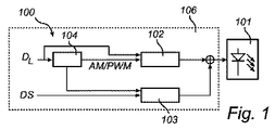
図示の手段として、CAMは、まず、2つの調光モードを利用している照明装置のために説明されている。図1は、本発明に従った照明装置100の一実施形態の概略的なブロック図を示している。当該照明装置は、ここでは、ドライバ106によって給電される発光ダイオード(LED)を具備する光源101を有する。当該光源は、代替的に、複数のLEDを有していてもよく、又は、代替的に、HID(高輝度放電)ランプ、ハロゲンランプ、白熱灯、及び/又は、蛍光管ランプに基づいていてもよい。
As a means of illustration, the CAM is first described for a lighting device that utilizes two dimming modes. FIG. 1 shows a schematic block diagram of an embodiment of a
ドライバ106は、調光レベルを決定し、光源101をオンオフ切り替えする。当該ドライバは、光源に給電するための電子ソフトウェア及びハードウェアを有し、少なくとも1つのプロセッサなどにおいて適切な処理能力を更に有し、オプションで、少なくとも1つのメモリ回路を有する。以下では、選択、処理、符号化などの異なる手段によって、ドライバの機能のみが説明される。当該機能は、ソフトウェア又はハードウェアによって実現され得る。
The
ドライバ106は、中央処理ユニット(CPU)などの処理ユニットを有するか、又は、オプションで、前記CPUの一部である。単一のプロセッサ又は他のユニットが、請求項に記載された幾つかの項目の機能を果たしてもよい。
The
ドライバ106は、ここではボックス104として図示されている現在の調光モードを選択するための手段とともに配置されている。オプションの(一方向)通信インタフェース(図示省略)を介して受信される情報に基づいて、調光レベルDL又は光源のオン/オフ切り替えが制御される。ここで、ボックス104は、例えば、リモートコントロール、コンピュータ化された制御システム、又は、手動の調光制御などである通信インタフェースから、要求された調光レベル値DLを読み出す。要求された調光レベル値DLに依存して、所定の調光方法が選択される。この例示的な実施形態では、調光レベルDLが所定の閾値レベル、例えば、照明装置からの最大光出力の10%よりも小さくなるように選択された場合、PWM−Dが、調光方法として用いられる。調光レベルDLが所定の閾値レベル以上となるように選択された場合、AM−Dが、調光方法として用いられる。代替的な実施形態では、所定の閾値レベルは、例えば、最大光出力の80%、75%、50%、40%、33%、又は、20%で設定され得る。換言すれば、閾値レベルより大きい調光レベルでは、光源は、要求される調光レベル(即ち、100%の光出力に対応する公称電流の特定の割合)に応じたDC電流で駆動され、当該電流レベルの周囲で変調される(図3a及び図3b参照)。閾値より小さい調光レベルでは、光源は、PWM変調された電流で駆動され、ここで、「電流(on current)」は、閾値レベルに応じたDC電流と同じであり、PWMデューティサイクルが、閾値レベルにおける調光レベル(デューティサイクル=100%)、又は、閾値レベルよりも小さい調光レベル(デューティサイクル<100%)を規定する(図2a及び図2b参照)。
照明装置100は、光出力の調光を供給するための調光手段、即ち、AM−D又はPWM−D調光された電流を生成するための回路(ここでは、ボックス102で示されている)を更に有する。ボックス104において選択されるような現在選択されている調光方法が、要求された調光レベルDLの情報とともにボックス102において採用され、次いで、ボックス102が、光源のための調光された駆動電流を出力する。
The
光源101の駆動回路は、ここでは、ボックス103で表されている、符号を光出力に埋め込むための埋め込み手段を更に有する。データ埋め込みに用いられる変調方法は、ここでは、現在の調光モードに応じて選択される。現在の調光モードに関するデータは、ここでは、ボックス104から抽出される。さらに、光出力の中に埋め込まれる実際のデータは、データソースDSから抽出され、当該データは、照明装置自体の内部にある制御回路、リモートコントロール、又は、照明装置含まれる照明システムのためのコンピュータ化された制御システムなどを介して供給され得る。データは、例えば、照明装置、現在の照明設定、照明装置の現在の照明測定、光源101の点灯時間などの照明装置に関するデータ、又は、テキストデータなどの通信データ、音楽データ、音声データ、ビデオデータ、温度センサ、電圧センサ、電流センサ、光センサなどからのセンサデータなどの任意の外部データの識別コードと関連付けられていてもよい。
The drive circuit of the
ボックス102からの調光された駆動電流と、ボックス103からのデータが埋め込まれた電流とが、独立した回路において生成され、LED101などの光源への入力部において合成される。特に、時間間隔Tにおける総光パワーは、ディジタルデータを埋め込むために変動されている。例えば、T間隔における高い総光パワーは、ビット「1」を意味し、T間隔における低い総光パワーは、ビット「0」を意味する。しかしながら、より長い期間における平均光パワーは、所望の調光レベルによって示される値と等しい。時間間隔Tは、埋め込まれるデータ及び適用される照明アプリケーションに依存して、(およそ)10nsから(およそ)1msまでの範囲にある。これは、約100Mビット/sから約1kビット/sの間のビットレートに対応している。好ましくは、時間間隔Tは、100nsから100μsまでの範囲にあり、より好ましくは、1μsから10μsまでの範囲にある。
The dimmed drive current from
上記記述が満足される限り、このデータ埋め込み方法の特定の実装に関しては自由である。例えば、以下で説明されるように、調光及びデータ埋め込みの両方を満足する光波形を同時に生成することができる。あるいは、照明装置100において、まず、ボックス102において調光された駆動電流を生成し、次いで、データ埋め込みのために信号を修正するという2段階のアプローチをとることができる。
As long as the above description is satisfied, the implementation of this data embedding method is free. For example, as described below, an optical waveform that satisfies both dimming and data embedding can be generated simultaneously. Alternatively, the
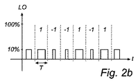
照明装置100は、二値符号変調を用いてもよい、即ち、データが、{−1、1}から選択されるデータ値のシーケンスである。これは、図2を参照して説明される。図2a及び図2bは、光源においてPWM−Dモードを採用した場合のCAMの実装を示している時間図である。図2aは、光源101の最大光出力(100%)の約5%の調光レベルを供給するために、パルス変調された、即ち、ボックス104においてPWM−Dが選択されている、ボックス102により供給される駆動電流を示している。この場合、一例として、閾値レベルは、10%に設定され、PWMデューティサイクルは、約50%に設定されている。(1/fPWM(fPWM:PWM周波数)に対応する)各時間間隔Tでは、各パルスが、各データ値を埋め込むために、CAMで変調されている。調光された駆動電流上に変調され、変調された調光済み駆動信号を示している図2bに表されているデータシーケンスは、ここでは、{*、1、−1、−1、1、−1、1、*}であり、*は、「データ無し」を示しており、従って、図2bに表されている最初の期間及び最後の期間は、駆動電流のデータ無し変調を含んでいる。「データ無し」間隔における、駆動信号、ひいては関連付けられた光出力は、用いられている特定の調光モード及び調光レベルによって決定される。例えば、PWM調光モードでは、「データ無し」信号は、調光レベルによって値が決定される無変動デューティサイクルを有するパルス列を含むように設定されることができる。
The
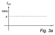
一方、照明装置100の調光レベルDLが上記閾値レベルとなるように選択された場合、上述のように、AM−D調光が採用される。照明装置100のための当該駆動モードにおけるCAMの実装が、図3を参照して以下説明される。図3a及び図3bは、光源においてAM−Dモードを採用した場合のCAMの実装を示している時間図である。図3aは、光源101の最大光出力(100%)のA%の総光出力を供給するために、振幅変調された、即ち、ボックス104においてAM−D調光が選択されている、ボックス102によって供給される駆動電流を示している。各時間間隔Tにおいて、調光された光出力は、各データ値を埋め込むために、CAMで変調される。調光された駆動電流上に変調され、変調された調光済み駆動信号を示している図3bに表されているデータシーケンスは、ここでは、{*、1、−1、−1、1、−1、1、*}であり、*は、「データ無し」を示しており、従って、図3bに表されている最初の期間及び最後の期間は、駆動電流のデータ無し変調を含んでいる。ここで、符号変調は、照明装置から出力される平均光レベルの振幅変調によりなされる。一般的に、変調深さは、要求される信号対ノイズ比及び照明システムにおいて許容される照明境界条件に依存して、1%と20%との間である。PWM調光モードで上述したように、「データ無し」間隔における、駆動信号、ひいては関連付けられた光出力は、用いられている特定の調光モード及び調光レベルによって決定される。AM調光モードでは、「データ無し」信号は、調光レベルによって値が決定されるDC(直流)信号を含むように設定されることができる。
On the other hand, when the dimming level DL of the
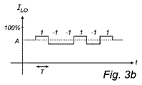
CAMは、二値符号変調よりも他の符号変調に適しており、図4a及び図4bでは、AM−Dモード駆動信号での4値変調(図4a)及びPWM−Dモード駆動信号での4値変調(図4b)が示されている。4つの異なるシンボル{−3、−1、1、3}が、調光された駆動信号の中に符号化されている。本発明の概念において、符号化レベルの数は、任意の特定の数のセットに限定されないことに留意すべきである。 CAM is more suitable for code modulation other than binary code modulation, and in FIGS. 4a and 4b, quaternary modulation with an AM-D mode drive signal (FIG. 4a) and 4 with a PWM-D mode drive signal. Value modulation (FIG. 4b) is shown. Four different symbols {-3, -1, 1, 3} are encoded in the dimmed drive signal. It should be noted that in the inventive concept, the number of encoding levels is not limited to any particular number of sets.
上記のように、照明装置に対してCAMが採用された全ての場合において、照明の瞬時の光パワー出力は、データ埋め込み要求のために変動するが、長い期間(>T)、例えば、0.01秒に亘る平均光出力は、同じに維持され、調光レベル要求に従う。本質的には、人間の目は、LEDランプの調光のみを感じるべきであり、データ埋め込みプロセスは、人間の目にとって不可視であるべきである。 As described above, in all cases where CAM is employed for the lighting device, the instantaneous light power output of the lighting varies due to data embedding requirements, but for a long period (> T), eg, 0. The average light output over 01 seconds remains the same and follows dimming level requirements. In essence, the human eye should feel only the dimming of the LED lamp, and the data embedding process should be invisible to the human eye.
上述したように、光源のための駆動電流は、調光レベル及びデータ埋め込み要求を併せて考慮して、単一の(論理)回路によって生成されてもよい。本発明の概念に従った照明装置のかかる実施形態は、図5に示されている。図5は、本発明の概念に従った照明装置200の一実施形態の概略的なブロック図を示している。照明装置200は、ここでは、ドライバ206によって電気的に駆動される、発光ダイオード(LED)を具備する光源101を有する。あるいは、光源は、図1において上述されたタイプのランプであってもよい。ドライバ206は、調光レベルを決定し、光源101をオンオフ切り替えする。ドライバ206は、図1の照明装置において前述したように、ボックス104で示される、現在の調光モードを選択するための手段を有する。オプションの(一方向)通信インタフェース(図示省略)を介して受信される情報に基づいて、光源の調光レベルDL又はオンオフ切り替えが制御される。ボックス104は、要求された調光レベル値DLを適切な通信インタフェースから抽出する。
As described above, the drive current for the light source may be generated by a single (logic) circuit, taking into account the dimming level and data embedding requirements together. Such an embodiment of a lighting device according to the inventive concept is shown in FIG. FIG. 5 shows a schematic block diagram of an embodiment of a
照明装置200は、光出力の調光及び符号化を供給するための手段、即ち、ここではボックス105で示される、AM−D又はPWM−D調光電流を生成するための回路及びデータ埋め込み手段を更に有する。ボックス104において選択された現在選択されている調光方法は、従って、ボックス105において、要求される調光レベルDLの情報とともに採用され、信号中に埋め込まれるデータは、図1において説明した照明装置100と同様の態様で、データソースDSから抽出される。次いで、ボックス105は、光源101を駆動するためにCAM変調された調光済み駆動電流を出力する。
The
データ埋め込みに用いられる変調方法は、ここでは、現在の調光モードに応じて選択される。現在の調光モードに関するデータは、ボックス104から抽出される。
Here, the modulation method used for data embedding is selected according to the current dimming mode. Data regarding the current dimming mode is extracted from
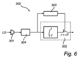
上記照明装置は、調光及び符号化された光を出力する。光に埋め込まれたデータを抽出するために、本発明の概念は、更に受信器に関する。図6は、本発明の概念に従った受信器300の一実施形態の概略的なブロック図である。受信器300は、本発明の概念に従った照明装置から発せられる信号LSを受信するための光センサ301を有しており、当該光センサ301は、オプションで、信号LSの光電変換のためのコンバータ304に接続される。光センサ及びコンバータは、代替的に、単一のセンサユニットの中に一体化されてもよい。受信器300は、ここでは、ボックス302で示される、受信した信号をインテグレート及びダンププロセスにより処理するとともに、当該処理の出力から符号を抽出するための手段を更に有する。結果として得られる記録される累積値の順序は、埋め込まれた符号と関連付けられている。このインテグレート及びダンププロセス、及び、埋め込まれた符号の抽出の出力部において、図2b及び図3bに示されるような、照明装置からの2つの変調済み光信号の両方が、上述のように、1/Tのレートの同じ符号シーケンスとなる。
The illumination device outputs light that is dimmed and encoded. In order to extract data embedded in light, the inventive concept further relates to a receiver. FIG. 6 is a schematic block diagram of one embodiment of a
オプションで、受信器300は、正確なTの値を得るように構成されたクロック同期ユニット303を有する。受信器が所定の理想的なTの値を知っているべきであるとしても、特定の照明装置における実際のTの値は、温度、湿度などの実際の環境に起因して、ある程度の不正確さをはらんでいる。従って、受信器におけるクロック同期ユニット303の役割は、理想の所定値に近い実際のTの値を回復することである。このクロック同期プロセスを助けるために、受信器が、対応する送信器、即ち、ここでは照明装置のための正確なTの値を回復できるように、通常、データシーケンスに対する既知の周期シーケンスについてのプレフィックスが実施される。
Optionally,
アナログフィルタリング、ディジタルフィルタリング、低ノイズ増幅、並びに、ライン符号化、誤り制御符号化、及び、パリティチェック符号化スキームなどに対して使用可能な復号化などの、受信器の他の側面は、本発明の範囲外であることが言及されるべきである。 Other aspects of the receiver, such as analog filtering, digital filtering, low noise amplification, and decoding that can be used for line coding, error control coding, parity check coding schemes, etc. It should be mentioned that it is out of scope.
受信器の一実施形態によれば、データ受信及び符号抽出に加えて、受信器は、照明装置から受信される光の信号強度についての推定を行なうように構成されている。 According to one embodiment of the receiver, in addition to data reception and code extraction, the receiver is configured to make an estimate of the signal strength of the light received from the lighting device.
受信器及び照明装置は、上述のように、中央処理装置(CPU)などの処理ユニットを有していてもよいし、又は、処理ユニットの一部であってもよい。単一のプロセッサ又は他のユニットが、請求項に記載の幾つかの項目の機能を果たしてもよい。 As described above, the receiver and the illumination device may have a processing unit such as a central processing unit (CPU) or may be a part of the processing unit. A single processor or other unit may fulfill the functions of several items recited in the claims.
当該技術分野における当業者は、本発明が、上記の好適な実施形態に決して限定されないことを理解する。反対に、多くの修正例及び変形例が、添付の請求項の範囲内において可能である。例えば、当該技術分野における当業者は、本発明の実施形態において、
PWM−Dモードが、上述のように、PWM電流パルス列がゼロとIthresholdとの間で切り替わらないが、代わりに、ゼロとシステムInominalの最大許容電流との間で切り替わるように構成されることを理解することができる。デューティサイクルは、要求される調光レベルを達成するために、同時に、Inominal/Ithresholdという係数によって、より小さい値に設定される必要があろう。このオプションは、比較的大きい(即ち、100%の光出力に比較的近い)調光レベルDLに対しては上手く機能するであろうが、極めて低いデューティサイクルを実装するのは困難/高価であるため、極めて低い(即ち、0%の光出力に比較的近い)調光レベルにおいては達成することが困難であろう。
Those skilled in the art will understand that the present invention by no means is limited to the preferred embodiments described above. On the contrary, many modifications and variations are possible within the scope of the appended claims. For example, one of ordinary skill in the art can use the embodiments of the present invention as follows:
The PWM-D mode is configured such that, as described above, the PWM current pulse train does not switch between zero and I threshold but instead switches between zero and the maximum allowable current of the system I nominal. Can understand. In order to achieve the required dimming level, the duty cycle will need to be set to a smaller value by the factor I nominal / I threshold at the same time. This option will work well for dimming levels DL that are relatively large (ie, relatively close to 100% light output), but difficult / expensive to implement very low duty cycles Thus, it will be difficult to achieve at very low dimming levels (ie, relatively close to 0% light output).
Claims (15)
光出力を供給するための少なくとも1つの光源と、
所定の調光方法とそれぞれ関連付けられる複数の調光モードから選択された現在の調光モードにより前記光出力の調光を供給するための手段と、
前記照明装置は、前記調光された光出力に符号を埋め込むための手段と、を有し、
前記調光された光出力に符号を埋め込むための手段は、期間Tにおける前記調光された光出力の積算値が前記符号を埋め込むために変調されるように、瞬時の調光された光出力を制御する、照明装置。 A lighting device,
At least one light source for providing light output;
Means for providing dimming of the light output according to a current dimming mode selected from a plurality of dimming modes each associated with a predetermined dimming method;
The illumination device comprises means for embedding a code in the dimmed light output;
The means for embedding the code in the dimmed light output is an instantaneous dimmed light output so that the integrated value of the dimmed light output in period T is modulated to embed the code. To control the lighting device.
インテグレート及びダンププロセスにより前記符号を抽出するための手段と、を有する受信器。 Means for receiving a signal emitted from a lighting device according to any one of claims 1 to 7,
Means for extracting said code by means of an integration and dump process.
長さTの複数の期間の各々に対して、
前記期間Tにおいて前記受信された信号を積分するステップと、
前記期間において前記受信された信号の積算値の結果を記録するステップと、を有し、
前記記録された積算値の結果の順序は、前記符号と関連付けられる、請求項8又は9に記載の受信器。 The integration and dump process includes:
For each of a plurality of periods of length T,
Integrating the received signal in the period T;
Recording the result of the integrated value of the received signal in the period,
The receiver according to claim 8 or 9, wherein the order of the recorded integrated value results is associated with the sign.
前記複数の調光モードから選択された現在の調光モードで調光されている場合、期間Tにおける前記調光された光出力の積算値が前記符号を埋め込むために変調されるように、前記照明装置からの瞬時の調光された光出力を制御するステップを有する、方法。 A code modulation method for a lighting device that employs a plurality of dimming modes, each representing dimming light output from a light source by each dimming method,
When dimming in a current dimming mode selected from the plurality of dimming modes, the integrated value of the dimmed light output in period T is modulated to embed the code Controlling the instantaneous dimmed light output from the lighting device.
Applications Claiming Priority (3)
| Application Number | Priority Date | Filing Date | Title |
|---|---|---|---|
| EP11165095.8 | 2011-05-06 | ||
| EP11165095 | 2011-05-06 | ||
| PCT/IB2012/052081 WO2012153220A1 (en) | 2011-05-06 | 2012-04-26 | Lighting device and receiver |
Publications (3)
| Publication Number | Publication Date |
|---|---|
| JP2014517451A true JP2014517451A (en) | 2014-07-17 |
| JP2014517451A5 JP2014517451A5 (en) | 2015-06-18 |
| JP6058636B2 JP6058636B2 (en) | 2017-01-11 |
Family
ID=46085673
Family Applications (1)
| Application Number | Title | Priority Date | Filing Date |
|---|---|---|---|
| JP2014508901A Expired - Fee Related JP6058636B2 (en) | 2011-05-06 | 2012-04-26 | Lighting device and receiver |
Country Status (7)
| Country | Link |
|---|---|
| US (1) | US9407365B2 (en) |
| EP (1) | EP2705730B1 (en) |
| JP (1) | JP6058636B2 (en) |
| CN (1) | CN103503564B (en) |
| BR (1) | BR112013028205A2 (en) |
| RU (1) | RU2604651C2 (en) |
| WO (1) | WO2012153220A1 (en) |
Families Citing this family (14)
| Publication number | Priority date | Publication date | Assignee | Title |
|---|---|---|---|---|
| CN102970129B (en) * | 2012-11-16 | 2013-10-30 | 深圳光启创新技术有限公司 | Time information-based signal encrypting and decrypting method and time information-based signal encrypting and decrypting device |
| DE102013014536B4 (en) * | 2013-09-03 | 2015-07-09 | Sew-Eurodrive Gmbh & Co Kg | Method for transmitting information and apparatus for carrying out the method |
| PL3103202T3 (en) | 2014-02-07 | 2018-07-31 | Danmarks Tekniske Universitet | Decoding a combined amplitude modulated and frequency modulated signal |
| FR3020908B1 (en) * | 2014-05-07 | 2017-09-15 | Commissariat Energie Atomique | OPTIMIZATION OF THE FLOW IN A LI-FI SYSTEM |
| US10009100B2 (en) | 2014-06-18 | 2018-06-26 | Qualcomm Incorporated | Transmission of identifiers using visible light communication |
| JP2017525258A (en) * | 2014-07-03 | 2017-08-31 | フィリップス ライティング ホールディング ビー ヴィ | Encoding optical symbols |
| EP3238507A1 (en) * | 2014-12-23 | 2017-11-01 | Chauvet & Sons, Inc. | Light fixture with multiple dimming capabilities |
| CN105307304B (en) * | 2015-10-14 | 2017-05-10 | 上海大学 | OPV-driven OLED light source and preparation method thereof |
| DE102016202505A1 (en) * | 2016-02-18 | 2017-08-24 | Osram Gmbh | A communication device and method for radiation-based communication between vehicles and vehicle with the communication device |
| WO2017190998A1 (en) * | 2016-05-04 | 2017-11-09 | Philips Lighting Holding B.V. | Controlling a light source |
| WO2018213998A1 (en) * | 2017-05-22 | 2018-11-29 | 华为技术有限公司 | Signal transmission method and device |
| JP6622782B2 (en) * | 2017-11-24 | 2019-12-18 | ファナック株式会社 | Control device, electronic device, and control system |
| CN108880682B (en) * | 2018-07-25 | 2020-02-07 | 中国人民解放军战略支援部队信息工程大学 | Coding-based visible light communication dimming control method and system |
| WO2023148071A1 (en) * | 2022-02-01 | 2023-08-10 | Signify Holding B.V. | Dimming control system for a light emitting arrangement |
Citations (7)
| Publication number | Priority date | Publication date | Assignee | Title |
|---|---|---|---|---|
| JP2008060222A (en) * | 2006-08-30 | 2008-03-13 | Seiko Epson Corp | Device and method for driving light-emitting element |
| JP2008071765A (en) * | 2007-11-01 | 2008-03-27 | Sharp Corp | Illumination device equipped with optical transmission mechanism |
| JP2009054425A (en) * | 2007-08-27 | 2009-03-12 | Panasonic Electric Works Co Ltd | Lighting apparatus |
| JP2010509797A (en) * | 2006-11-03 | 2010-03-25 | コーニンクレッカ フィリップス エレクトロニクス エヌ ヴィ | Receiver for modulated optical signal and method for receiving modulated optical signal |
| WO2010064175A1 (en) * | 2008-12-04 | 2010-06-10 | Koninklijke Philips Electronics N.V. | Illumination device and method for embedding a data signal in a luminance output using ac driven light sources |
| JP2010533948A (en) * | 2007-07-16 | 2010-10-28 | コーニンクレッカ フィリップス エレクトロニクス エヌ ヴィ | Driving the light source |
| JP2011505053A (en) * | 2006-11-30 | 2011-02-17 | コーニンクレッカ フィリップス エレクトロニクス エヌ ヴィ | Intrinsic flux detection |
Family Cites Families (13)
| Publication number | Priority date | Publication date | Assignee | Title |
|---|---|---|---|---|
| JP2000049712A (en) * | 1998-05-28 | 2000-02-18 | Sharp Corp | Digital optical communication equipment and method therefor |
| US6661975B1 (en) * | 2000-03-10 | 2003-12-09 | Northrop Grumman Corporation | Multi-rate variable duty cycle modem for use in an optical communication system |
| US20080193139A1 (en) * | 2004-12-01 | 2008-08-14 | Ido Bettesh | Two-Way Communication in an Autonomous in Vivo Device |
| CA2609877C (en) | 2005-01-25 | 2015-05-26 | Tir Technology Lp | Method and apparatus for illumination and communication |
| CN101395826B (en) | 2006-03-02 | 2012-04-11 | 皇家飞利浦电子股份有限公司 | A lighting device |
| US8494367B2 (en) * | 2006-06-28 | 2013-07-23 | Koninklijke Philips Electronics N.V. | Method and device for modulating the light emission of a lighting device |
| CN101971704B (en) | 2008-03-12 | 2016-09-14 | 皇家飞利浦电子股份有限公司 | The configuration of illuminator system |
| JP2012523659A (en) | 2009-04-08 | 2012-10-04 | コーニンクレッカ フィリップス エレクトロニクス エヌ ヴィ | Illumination device having state indication information by modulated light |
| US9319134B2 (en) * | 2009-04-28 | 2016-04-19 | Siemens Aktiengesellschaft | Method and device for optically transmitting data |
| DE102010005885A1 (en) | 2009-04-28 | 2010-11-18 | Fraunhofer-Gesellschaft zur Förderung der angewandten Forschung e.V. | Method and device for the optical transmission of data |
| US20100322635A1 (en) * | 2009-06-18 | 2010-12-23 | Sony Ericsson Mobile Communications Ab | Using ambient led light for broadcasting info and navigation |
| US8447189B2 (en) * | 2009-09-21 | 2013-05-21 | Electronics And Telecommunications Research Institute | Transmitter, receiver for visible light communication and method using the same |
| US8666259B2 (en) * | 2010-10-07 | 2014-03-04 | Electronics And Telecommunications Research Institute | Data transmitting and receiving apparatus and method for visible light communication |
-
2012
- 2012-04-26 JP JP2014508901A patent/JP6058636B2/en not_active Expired - Fee Related
- 2012-04-26 EP EP12721358.5A patent/EP2705730B1/en active Active
- 2012-04-26 WO PCT/IB2012/052081 patent/WO2012153220A1/en active Application Filing
- 2012-04-26 BR BR112013028205A patent/BR112013028205A2/en not_active Application Discontinuation
- 2012-04-26 CN CN201280021994.4A patent/CN103503564B/en not_active Expired - Fee Related
- 2012-04-26 US US14/115,524 patent/US9407365B2/en active Active
- 2012-04-26 RU RU2013154111/07A patent/RU2604651C2/en not_active IP Right Cessation
Patent Citations (7)
| Publication number | Priority date | Publication date | Assignee | Title |
|---|---|---|---|---|
| JP2008060222A (en) * | 2006-08-30 | 2008-03-13 | Seiko Epson Corp | Device and method for driving light-emitting element |
| JP2010509797A (en) * | 2006-11-03 | 2010-03-25 | コーニンクレッカ フィリップス エレクトロニクス エヌ ヴィ | Receiver for modulated optical signal and method for receiving modulated optical signal |
| JP2011505053A (en) * | 2006-11-30 | 2011-02-17 | コーニンクレッカ フィリップス エレクトロニクス エヌ ヴィ | Intrinsic flux detection |
| JP2010533948A (en) * | 2007-07-16 | 2010-10-28 | コーニンクレッカ フィリップス エレクトロニクス エヌ ヴィ | Driving the light source |
| JP2009054425A (en) * | 2007-08-27 | 2009-03-12 | Panasonic Electric Works Co Ltd | Lighting apparatus |
| JP2008071765A (en) * | 2007-11-01 | 2008-03-27 | Sharp Corp | Illumination device equipped with optical transmission mechanism |
| WO2010064175A1 (en) * | 2008-12-04 | 2010-06-10 | Koninklijke Philips Electronics N.V. | Illumination device and method for embedding a data signal in a luminance output using ac driven light sources |
Also Published As
| Publication number | Publication date |
|---|---|
| US9407365B2 (en) | 2016-08-02 |
| WO2012153220A1 (en) | 2012-11-15 |
| RU2013154111A (en) | 2015-06-20 |
| JP6058636B2 (en) | 2017-01-11 |
| EP2705730A1 (en) | 2014-03-12 |
| CN103503564B (en) | 2017-06-09 |
| CN103503564A (en) | 2014-01-08 |
| BR112013028205A2 (en) | 2017-01-17 |
| US20140072310A1 (en) | 2014-03-13 |
| RU2604651C2 (en) | 2016-12-10 |
| EP2705730B1 (en) | 2019-07-03 |
Similar Documents
| Publication | Publication Date | Title |
|---|---|---|
| JP6058636B2 (en) | Lighting device and receiver | |
| JP5171393B2 (en) | Visible light communication system | |
| JP6009450B2 (en) | Modulation for coded optical transmission | |
| US7496297B2 (en) | LED system for illumination and data transmission | |
| JP6339293B2 (en) | Driving lighting elements | |
| CN108353486B (en) | Coded light modulation device | |
| JP2014517451A5 (en) | ||
| JP2010056644A (en) | Visible light communication system | |
| CN102474942B (en) | Method and device for driving a lamp | |
| JP2011082871A (en) | Transmission circuit, transmission method, and dimming information transmitting circuit of lighting equipment | |
| WO2017190998A1 (en) | Controlling a light source | |
| JP6554237B2 (en) | Coded light transmitter, coded light receiver, coded light transmission method, and coded light reception method | |
| JP4661763B2 (en) | Optical transmission system | |
| JP6482682B2 (en) | Optical signal generator, optical signal receiver, and optical communication system | |
| US20150359063A1 (en) | Electronic lighting system and method for lighting synchronization | |
| CN113811039B (en) | Light modulation circuit | |
| WO2017191010A1 (en) | Two-way communication using leds | |
| US20090123161A1 (en) | Led system for illumination and data transmission | |
| KR101507635B1 (en) | Electronic Dimming Device Comprises Switch and Dimmer which communicate using AC Switch line. | |
| JP4736886B2 (en) | Illumination light transmission system |
Legal Events
| Date | Code | Title | Description |
|---|---|---|---|
| A521 | Request for written amendment filed |
Free format text: JAPANESE INTERMEDIATE CODE: A523 Effective date: 20150420 |
|
| A621 | Written request for application examination |
Free format text: JAPANESE INTERMEDIATE CODE: A621 Effective date: 20150420 |
|
| RD02 | Notification of acceptance of power of attorney |
Free format text: JAPANESE INTERMEDIATE CODE: A7422 Effective date: 20151005 |
|
| A977 | Report on retrieval |
Free format text: JAPANESE INTERMEDIATE CODE: A971007 Effective date: 20160224 |
|
| A131 | Notification of reasons for refusal |
Free format text: JAPANESE INTERMEDIATE CODE: A131 Effective date: 20160225 |
|
| A711 | Notification of change in applicant |
Free format text: JAPANESE INTERMEDIATE CODE: A711 Effective date: 20160330 |
|
| RD02 | Notification of acceptance of power of attorney |
Free format text: JAPANESE INTERMEDIATE CODE: A7422 Effective date: 20160408 |
|
| RD04 | Notification of resignation of power of attorney |
Free format text: JAPANESE INTERMEDIATE CODE: A7424 Effective date: 20160418 |
|
| A521 | Request for written amendment filed |
Free format text: JAPANESE INTERMEDIATE CODE: A523 Effective date: 20160516 |
|
| TRDD | Decision of grant or rejection written | ||
| A01 | Written decision to grant a patent or to grant a registration (utility model) |
Free format text: JAPANESE INTERMEDIATE CODE: A01 Effective date: 20161109 |
|
| A61 | First payment of annual fees (during grant procedure) |
Free format text: JAPANESE INTERMEDIATE CODE: A61 Effective date: 20161207 |
|
| R150 | Certificate of patent or registration of utility model |
Ref document number: 6058636 Country of ref document: JP Free format text: JAPANESE INTERMEDIATE CODE: R150 |
|
| S531 | Written request for registration of change of domicile |
Free format text: JAPANESE INTERMEDIATE CODE: R313531 |
|
| S533 | Written request for registration of change of name |
Free format text: JAPANESE INTERMEDIATE CODE: R313533 |
|
| R350 | Written notification of registration of transfer |
Free format text: JAPANESE INTERMEDIATE CODE: R350 |
|
| R250 | Receipt of annual fees |
Free format text: JAPANESE INTERMEDIATE CODE: R250 |
|
| R250 | Receipt of annual fees |
Free format text: JAPANESE INTERMEDIATE CODE: R250 |
|
| LAPS | Cancellation because of no payment of annual fees |